

Page 1
BEDIENUNGSANLEITUNG
INSTRUCTION MANUAL
High Quality Product by
HXA 400
HXA 500
HXA 500 Q
MADE IN GERMANY
MK II
Page 2

DEUTSCH
2
HCC 1
HCC 2
HCC 3
HCC 4
HCC 5
HCC 6
Sehr geehrter Kunde,
wir gratulieren Ihnen zum Kauf dieser hochwertigen
HELIX Endstufe aus deutscher Fertigung. Diese Verstärker wurden nach neuesten technischen Erkenntnissen entwickelt und zeichnen sich durch hervorragende
Verarbeitung und überzeugende Technologie aus. Somit
ergänzen sie perfekt die HELIX Produktlinie von
AUDIOTEC FISCHER.
Um alle Möglichkeiten optimal ausschöpfen zu können,
lesen Sie bitte sorgfältig die nachfolgenden Installationshinweise. Wir garantieren, daß jedes Gerät vor
Versand auf seinen einwandfreien Zustand überprüft
wurde.
Viel Freude an diesem Produkt wünscht Ihnen das Team
von AUDIOTEC FISCHER.
Allgemeines zum Einbau von HELIX-Verstärkern
Vor Beginn der Installation unterbrechen Sie den
Minusanschluß der Autobatterie. Wir empfehlen Ihnen
die Installation von einem Einbauspezialisten vornehmen zu lassen, da der Nachweis eines fachgerechten
Einbaus und Anschlusses des Gerätes Voraussetzung für
die Garantieleistungen sind.
Installieren Sie Ihren Verstärker an einer trockenen
Stelle im Auto, die für eine Kühlung des Gerätes eine
ausreichende Luftzirkulation gewährleistet.
Im Sinne der Unfallsicherheit muß der Verstärker professionell befestigt werden. Dieses geschieht über die
4 beiliegenden Schrauben, die in eine Montagefläche
eingeschraubt werden, die genügend Halt bieten muß.
Bevor Sie die Schrauben im Montagefeld befestigen,
vergewissern Sie sich, daß keine elektrischen Kabel und
Komponenten, hydraulische Bremsleitungen, der
Benzintank etc. dahinter verborgen sind. Diese könnten
sonst beschädigt werden. Achten Sie darauf, daß solche
Teile sich auch in der doppelten Wandverkleidung verbergen können.
Anschluß der Verstärker
Der Verstärker darf nur in Kraftfahrzeuge eingebaut
werden, die den 12V Minuspol an Masse haben. Bei
anderen Systemen können der Verstärker und die elektrische Anlage des Kfz beschädigt werden.
Die Plusleitung für die gesamte Anlage sollte in einem
Abstand von max. 30 cm von der Batterie mit einer
Hauptsicherung abgesichert werden. Der Wert der
Sicherung errechnet sich aus der maximalen Stromaufnahme der Car-Hifi Anlage. Die Kabelverbindungen
müssen so verlegt sein, daß keine Klemm-, Quetschoder Bruchgefahr besteht. Bei scharfen Kanten
(Blechdurchführungen) müssen alle Kabel gegen
Durchscheuern gepolstert sein.
Ferner dürfen die Stromversorgungskabel niemals mit
Zuleitungen zu Vorrichtungen des Kfz (Lüftermotoren,
Brandkontrollmodulen, Benzinleitungen etc.) verlegt
werden.
Um eine sichere Installation zu gewährleisten, sollte auf
hohe Qualität der verwendeten Anschlußmaterialien
geachtet werden. Fragen Sie Ihren Fachhändler nach
HELIX Zubehör.
HELIX Cross Cards (HCCs)
Alle HELIX Endstufen werden ab Werk mit einer HCC 1
bestückt. Um das Einsatzspektrum Ihrer HELIX
Endstufe noch flexibler zu machen, gibt es bei Ihrem
Fachhändler weitere HCCs als optionale
Erweiterungen:
Für alle Module gilt:
Low Pass: rote LED leuchtet
High Pass: gelbe LED leuchtet
Full Range: grüne LED leuchtet
Band Pass: rote und gelbe LED leuchten
(Schalterstellung “low pass”)
HCC 1 85 Hz HP/LP
HCC 2 85 Hz HP/LP incl. Subsonic
HCC 3 LP: 60-500 Hz / HP: 60-700 Hz
HCC 4 LP: 300 Hz-5 kHz / HP: 500 Hz-7 kHz
HCC 5 LP: 300 Hz-5 kHz / HP: 60-700 Hz
für Bandpass
HCC 6 LP: 120-250 Hz / HP: 60-90 Hz
für Bandpass (Kickbass)
Crosskarten HCC
Pot.: LP1/LP2
Pot.: LP1/LP2
Pot.: LP1/LP2
Pot.: LP1/LP2
Pot.: HP1/HP2
Pot.: HP1/HP2
Pot.: HP1/HP2
Pot.: HP1/HP2
HP1 LP1
LP2 HP2
dB
0
-5
-10
-15
20 10050 200 50010
dB
0
-5
-10
-15
20 10050 200 500 1K15 Hz
10
dB
0
-5
-10
-15
20 10050 200 500 1K15 Hz
10
dB
0
-5
-10
-15
100 1K200 500 5K
dB
0
-5
-10
-15
20 10050 200 500 1K15 Hz
10
variabel
variabel
variabel
variabel
1K15 Hz
10K2K Hz
70
60
70
60
400
300
70
60
90
Hz
100
Hz
500
Hz
100
Hz
dB
0
-5
-10
-15
20 10050 200 500 1K15 Hz
10
dB
110
170
500
150
250
700
750
1,3K
5K
150
250
700
0
-5
-10
-15
100 1K200 500 5K
dB
0
-5
-10
-15
100 1K200 500 5K
dB
0
-5
-10
-15
20 10050 200 500 1K15 Hz
10
dB
0
-5
-10
-15
20 10050 200 500 1K15 Hz
10
variabel
10K2K Hz
variabel
10K2K Hz
variabel
variabel
400
300
600
500
135
120
60
50
500
750
1,3K
5K
Hz
800
1,3K
2,5K
7K
Hz
150
180
220
Hz
70
80
90
Hz
Page 3

Technische Daten HXA 400 MK II
Ausgangsleistung pro Kanal an 4 Ohm . . . . . . . . . . . . . . . . . . . . . . . . . . . . . . . . . . . . 4 x 65/85 Watt RMS/Musik
Ausgangsleistung pro Kanal an 2 Ohm . . . . . . . . . . . . . . . . . . . . . . . . . . . . . . . . . . . 4 x 100/150 Watt RMS/Musik
Ausgangsleistung gebrückt an 4 Ohm . . . . . . . . . . . . . . . . . . . . . . . . . . . . . . . . . . . . 2 x 200/300 Watt RMS/Musik
Frequenzbereich . . . . . . . . . . . . . . . . . . . . . . . . . . . . . . . . . . . . . . . . . . . . . . . . . . . . . . 20 Hz - 20 kHz, +/- 0,2 dB
Klirrfaktor . . . . . . . . . . . . . . . . . . . . . . . . . . . . . . . . . . . . . . . . . . . . . . . . . . . . . . . . . . . . . . . . . . . . . . . . < 0,009%
TIM . . . . . . . . . . . . . . . . . . . . . . . . . . . . . . . . . . . . . . . . . . . . . . . . . . . . . . . . . . . . . . . . . . . . . . . . . . . . . < 0,016%
Geräuschspannungsabstand . . . . . . . . . . . . . . . . . . . . . . . . . . . . . . . . . . . . . . . . . . . . . . . . . . . . . . . . . . . > 100 dB
Eingangsimpedanz . . . . . . . . . . . . . . . . . . . . . . . . . . . . . . . . . . . . . . . . . . . . . . . . . . . . . . . . . . . . . . . . . . 10 kOhm
Eingangsempfindlichkeit . . . . . . . . . . . . . . . . . . . . . . . . . . . . . . . . . . . . . . . . . . . . . . . . . . . . . . . . . . 700 mV - 8 V
Sicherung . . . . . . . . . . . . . . . . . . . . . . . . . . . . . . . . . . . . . . . . . . . . . . . . . . . . . . . . . . . . . . . . . . . . .2 x 25 Ampere
Abmessungen (H x B x T) in mm . . . . . . . . . . . . . . . . . . . . . . . . . . . . . . . . . . . . . . . . . . . . . . . . . 31,5 x 200 x 336
Gewicht netto . . . . . . . . . . . . . . . . . . . . . . . . . . . . . . . . . . . . . . . . . . . . . . . . . . . . . . . . . . . . . . . . . . . . . . . . 2,6 kg
3
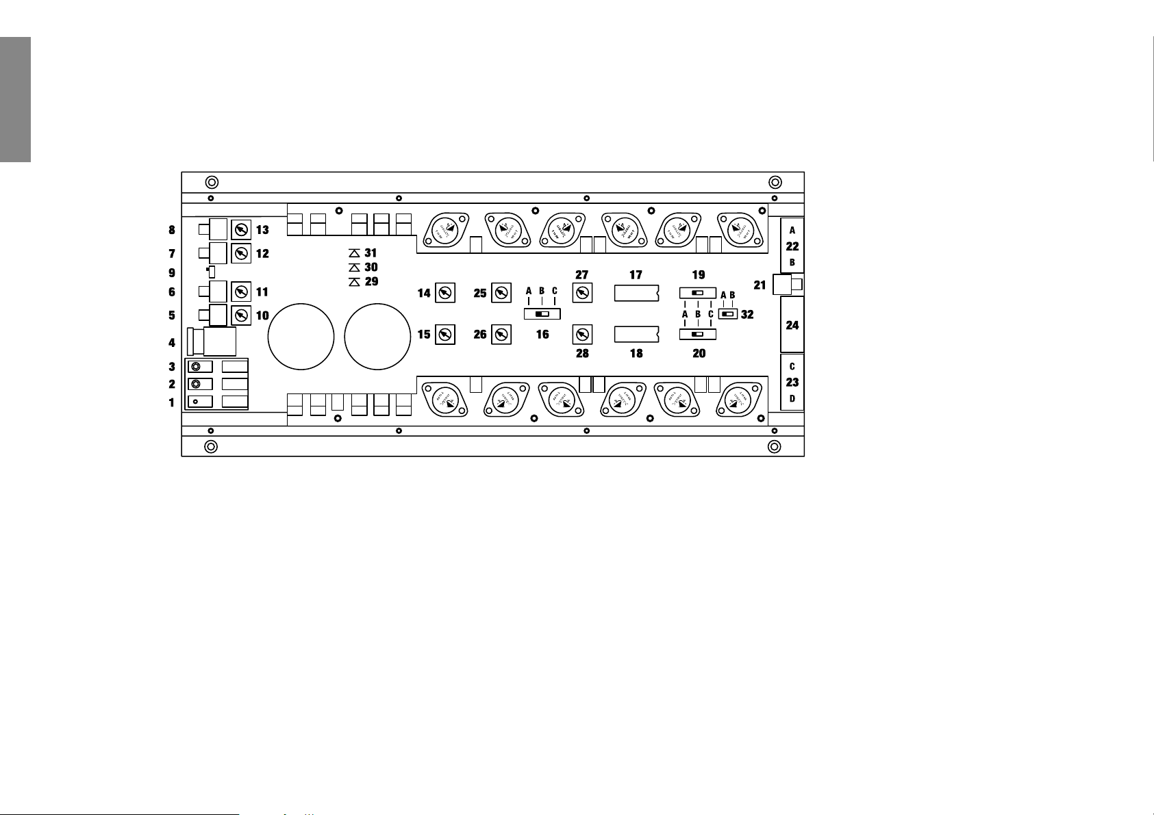
1 Anschluß Remoteleitung
Die Remoteleitung wird mit dem automatischen Antennenanschluß des Steuergerätes (Radio) verbunden.
Dieser ist nur aktiviert, wenn das Steuergerät EIN-geschaltet ist. Somit wird der Verstärker mit dem Steuergerät ein-und ausgeschaltet.
2 Anschluß Massekabel
Das Massekabel sollte am zentralen Massepunkt (dieser befindet sich dort wo der Minuspol der Batterie
zum Metallchassis des Kfz geerdet ist) oder an einer
blanken, von Lackresten befreiten Stelle des Kfz-Chassis angeschlossen werden.
3 Anschluß Batteriekabel
Das +12V Versorgungskabel ist am Pluspol der Batterie
anzuschließen. Empfohlener Querschnitt: min. 10 mm
2
.
4 Sicherung
Die Eingangssicherungen sind parallel geschaltet und
schützen vor einem geräteinternen Fehler, d.h. die Anlage muß mit einer zusätzlichen Sicherung in Nähe der
Batterie (max. 30 cm entfernt) abgesichert werden.
Die
Sicherungswerte betragen 2 x 25 Ampere und müssen
beide installiert sein, da der Verstärker mit 50 Ampere
(2 x 25 A) abgesichert ist.
5 - 8 Signaleingänge
Die HXA 400 MK II hat RCA-Anschlüsse zum
Kontaktieren von Cinchkabeln, welche mit den
Vorverstärkerausgängen der Line-Outputs des Steuergerätes oder eines Vorverstärkers z.B. HXE 100
verbunden werden. Diese Anschlüsse sind vergoldet,
um eine bessere NF-Übertragung zu gewährleisten.
9 - 12 Levelregler für Eingangsempfindlichkeit
Mit Hilfe dieser Regler kann die Eingangsempfindlichkeit der einzelnen Kanäle A bis D an die
Ausgangsspannung des angeschlossenen Steuergerätes
angepaßt werden. Diese Regler sind keine Lautstärkeregler, sondern dienen
nur der Anpassung. Der Regelbe-
reich ist 700 mV bis 8 V.
13 Schalter für die Kanäle Aund B
zur Umschaltung der Frequenzweichensteckmodule
auf Hochpass/ Full Range oder Tiefpass.
14 Schalter für die Kanäle C und D
zur Umschaltung der Frequenzweichensteckmodule
auf Hochpass/ Full Range oder Tiefpass.
15 - 16 Mono/Stereo Selecor
Mit diesen Schaltern kann die Betriebsart der Endstufe
festgelegt werden. Nutzen Sie den Verstärker im
4-Kanalbetrieb, so müssen sich beide Schalter in Stereo Position befinden. Nutzen Sie den Verstärker im
3-Kanalbetrieb (Frontsystem/Subwoofer), stellen Sie
den Schalter für das Frontsystem auf Stereo und den
Schalter für den Subwoofer auf Mono/Bridged.
Achtung:
Die Impedanz des Woofers darf im Brückenbetrieb
3 Ohm nicht unterschreiten.
17 - 18 Frequenzweichensteckmodule
Die HXA 400 MK II ist standardmäßig mit zwei
Frequenzmodulen 85 Hz/12 dB Oct. ausgestattet.
Weitere Module, wie z.B. variable Hoch-/Tiefpassfilter, sind auf Wunsch lieferbar. Die einzelnen Funktionen der Module werden durch farbige LED’s optisch
angezeigt.
So gilt für alle Module:
gelb = Hochpass
grün = Full Range
rot = Tiefpass
Die Module können auf Wusch mit 28 Hz/18 dB Oct.
Subsonicfilter geliefert werden.
19
Lautsprecheranschlußklemme für Kanäle A u. B
20
Lautsprecheranschlußklemme für Kanäle C u. D
21 - 23 CPS-Colour Protection System
Die LED’s zeigen den Betriebszustand der Endstufe an.
Grün = betriebsbereit; gelb = Fehlfunktion der Endstufe.
Kurzschluß am Lautsprecherausgang: rot = Überhit-
zung. Sollte die Endstufe wegen Überhitzung abgeschaltet haben, kann es je nach Umgebungstemperatur
einige Zeit dauern, bis sie sich wieder einschaltet.
Wichtiger Hinweis!
Verbinden Sie niemals die Lautsprecherleitungen mit
der Kfz-Masse (Chassis). Dieses kann Ihren Verstärker
zerstören. Achten Sie darauf, daß alle Lautsprechersysteme phasenrichtig angeschlossen sind, d.h. Plus zu
Plus und Minus zu Minus. Der Pluspol ist bei den meisten Lautsprechern gekennzeichnet. Außerdem können
bei dem Verstärker die Kanäle A und B sowie C und D
sowohl Stereo als auch Mono (gebrückt) betrieben
werden. Neben dem Stereo- und Monobetrieb kann die
Endstufe auch im Tri-mode angeschlossen werden, d.h.
sie können an einem Kabelpaar A/B oder C/D zwei
Stereolautsprecher betreiben und gleichzeitig einen
dritten Lautsprecher im Monobetrieb dazuschalten. Die
verschiedenen Anschlußmöglichkeiten entnehmen Sie
bitte dem beiliegenden Basic Instruction Sheet.
HXA 400
MK II
Page 4
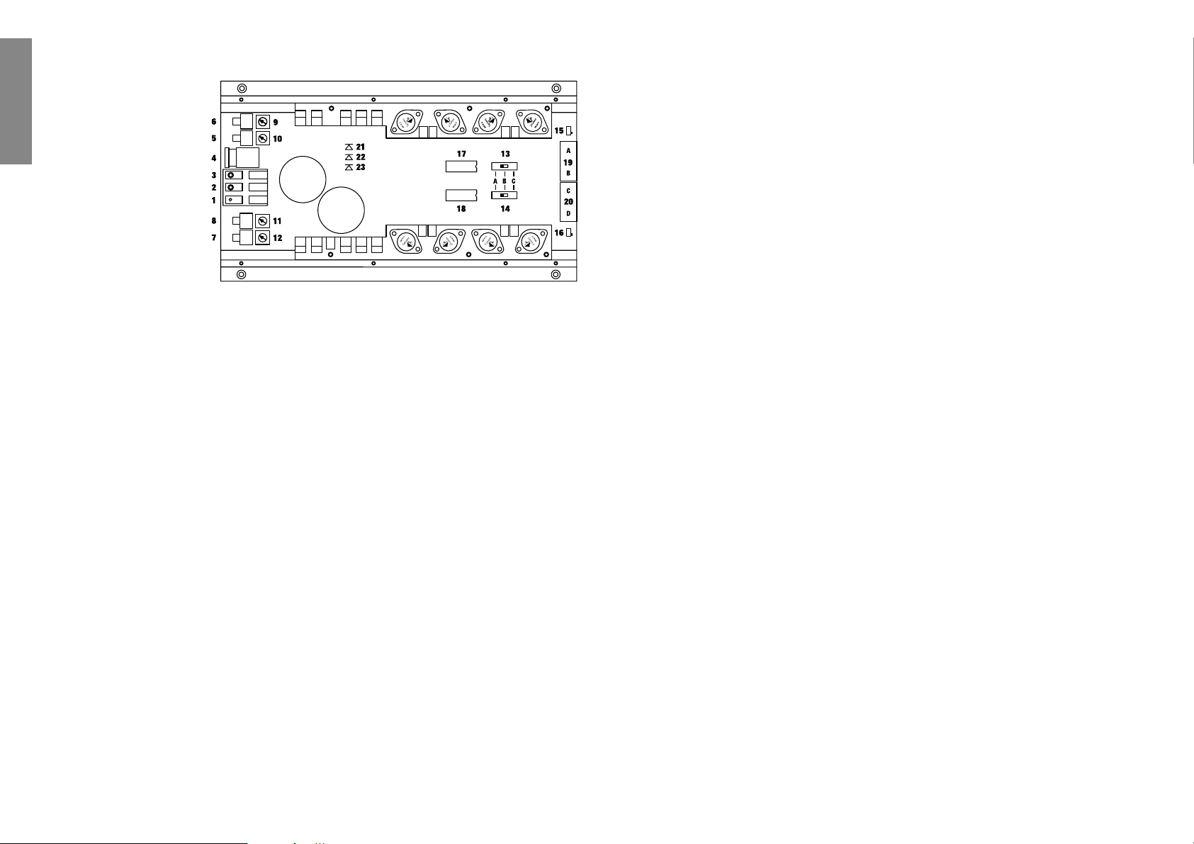
1 Anschluß Remoteleitung
Die Remoteleitung wird mit dem automatischen
Antennenanschluß des Steuergerätes (Radio) verbunden. Dieser ist nur aktiviert, wenn das Steuergerät EINgeschaltet ist. Somit wird der Verstärker mit dem
Steuergerät ein-und ausgeschaltet.
2 Anschluß Massekabel
Das Massekabel sollte am zentralen Massepunkt (dieser
befindet sich dort wo der Minuspol der Batterie zum
Metallchassis des Kfz geerdet ist) oder an einer blanken,
von Lackresten befreiten Stelle des Kfz-Chassis angeschlossen werden.
3 Anschluß Batteriekabel
Das +12V Versorgungskabel ist am Pluspol der Batterie
anzuschließen. Empfohlener Querschnitt: min. 10 mm
2
.
4 Sicherung
Die Eingangssicherungen sind parallel geschaltet und
schützen vor einem geräteinternen Fehler, d.h. die
Anlage muß mit einer zusätzlichen Sicherung in Nähe
der Batterie (max. 30 cm entfernt) abgesichert werden.
Die Sicherungswerte betragen 2 x 30 Ampere und müssen beide installiert sein, da der Verstärker mit 60
Ampere (2 x 30 A) abgesichert ist.
5 - 8 Signaleingänge
Die HXA 500 MK II/HXA500 Q MK II haben RCAAnschlüsse zum Kontaktieren von Cinchkabeln, welche
mit den Vorverstärkerausgängen der Line-Outputs des
Steuergerätes oder eines Vorverstärkers z.B. HXE 100
verbunden werden. Diese Anschlüsse sind vergoldet, um
eine bessere NF-Übertragung zu gewährlsten.
Highpower-Ausgänge von Radios o.ä. Geräten
dürfen nicht direkt angeschlossen werden!
9 Schalter für Signaleingänge
Sollte nur ein Stereosignal, d.h. zwei Cinchleitungen zur
Verfügung stehen, können die Eingänge mit Hilfe dieses
Schalters (Schalterstellung 2) von A nach C und von B
nach D verbunden werden. Auf Schalterstellung 1 sind
alle Eingänge getrennt.
DEUTSCH
1 Anschluß Remoteleitung
2 Anschluß Massekabel
3 Anschluß Batteriekabel
4 Sicherung
5 - 8 Signaleingänge
9 Schalter für Signaleingänge
10 - 13 Levelregler für Eingangsempfindlichkeit
14 Aktiver Tiefpass - Filter
15 Levelregler für den Subwooferverstärker
16 Eingangsschalter für den
Subwooferverstärker
17 - 18 Frequenzweichensteckmodule
19 Schalter für Kanäle Aund B
20 Schalter für Kanäle C und D
21 Cinch Ein- bzw. Ausgang
22 Lautsprecheranschlußklemmen für
Kanäle Aund B
23 Lautsprecheranschlußklemmen für
Kanäle C und D
24 Lautsprecheranschlußklemmen für
Subwoofer
25 Einstellung der Mittenfrequenzen
26 Pegelregler zur Anhebung der
Mittenfrequenzen
27 Einstellung der Bandbreite
28 Phasenregler
29 - 31 CPS-Colour Protection System
32 Schalter für Brückenbetrieb
4
HXA 500 MK II
HXA 500 Q MK II
Page 5

10 - 13 Levelregler fürEingangsempfindlichkeit
Mit Hilfe dieser Regler kann die Eingangsempfindlichkeit der einzelnen Kanäle A bis D an die
Ausgangsspannung des angeschlossenen Steuergerätes
angepaßt werden. Diese Regler sind keine Lautstärkeregler, sondern dienen
nur der Anpassung. Der
Regelbereich ist 700 mV bis 8 V.
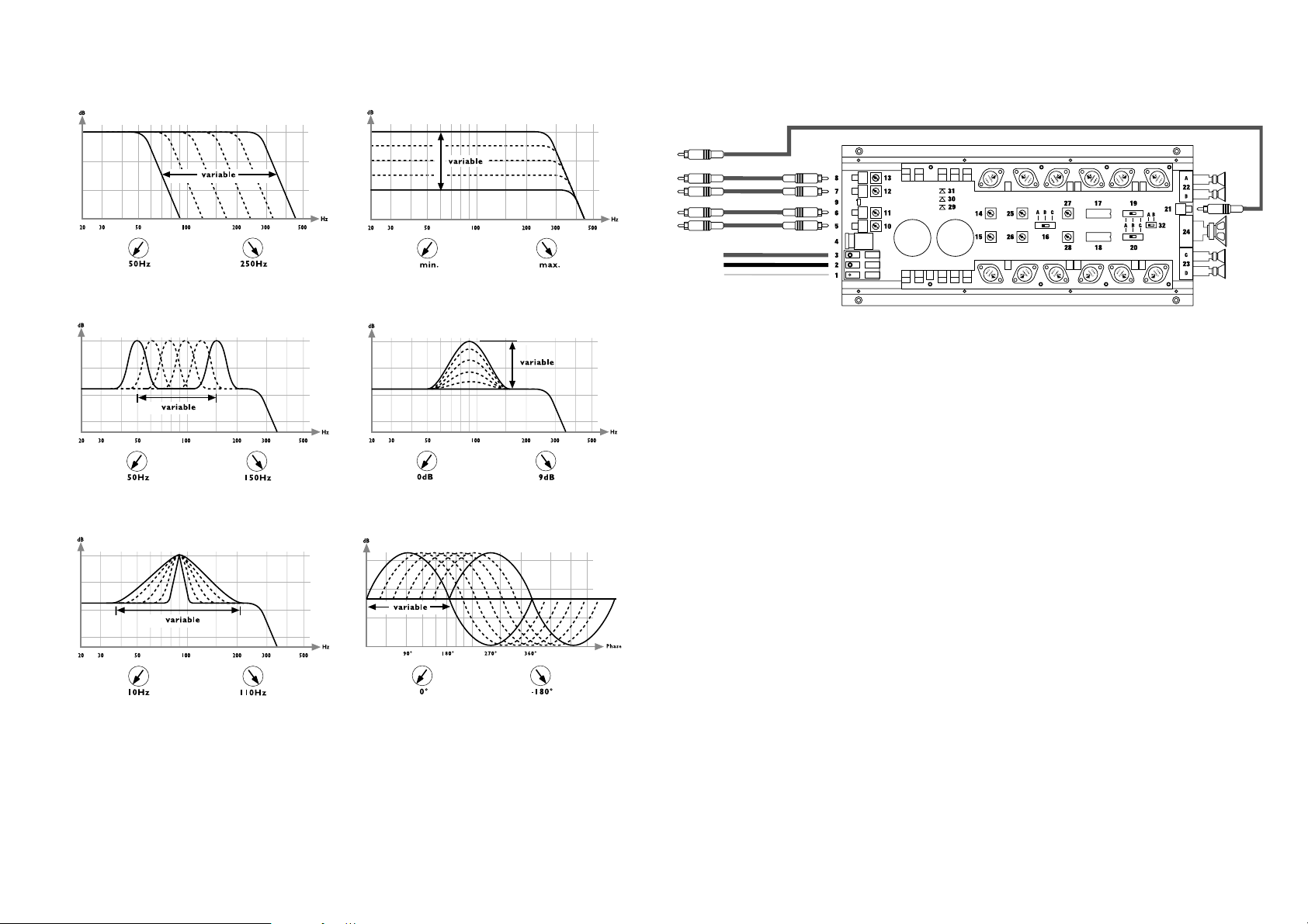
14 Aktiver Tiefpass-Filter
Mit diesem Regler kann der Frequenzsbereich des integrierten Subwooferverstärkers stufenlos von 50 - 250 Hz
eingestellt werden (s. Abb. 1).
15 Levelregler für den Subwooferverstärker
Mit Hilfe dieses Reglers kann der Pegel des
Subwoofers,
unabhängig von den anderen Kanälen,
nach Bedarf ein-
gestellt werden. (s. Abb. 2).
16 Eingangswahlschalter für Subwooferverstärker
Schaltstellung A
Der Subwooferverstärker arbeitet mit dem Summensignal der 4 Eingänge wobei der Eingangspegel der einzelnen Kanäle berücksichtigt wird. Der Frequenzbereich
wird mit Hilfe des Tiefpass-Filters Nr. 14 eingestellt.
Zusätzlich liegt an der Cinchbuchse Nr. 21 ein MonoSummensignal an, das z.B. für die Ansteuerung eines
Centerspeakerverstärkers verwendet werden kann.
Schaltstellung B (nur HXA 500 MK II)
Die Cinchbuchse Nr. 21 wird als Eingang des Subwooferverstärkers geschaltet. Das Signal kann mit Hilfe
der integrierten Aktivweiche Regler Nr. 14 und Nr. 15
eingestellt werden.
Schaltstellung B (nur HXA 500 Q MK II)
Die Cinchbuchse Nr. 24 wird als Eingang des Subwooferverstärkers geschaltet. Das Signal kann mit Hilfe
integrierten Aktivweiche Regler Nr. 14 und Nr. 15 und
des parametrischen Equalizers Regler Nr. 25 bis
Nr. 28 eingestellt werden.
Schaltstellung C (nur HXA 500 MK II)
Die Cinchbuchse Nr. 21 wird als direkter Eingang des
Subwooferverstärkers geschaltet. Dieses ist sinnvoll,
wenn ein Signal speziell für den Subwooferverstärker,
z.B. von einem Equalizer, zur Verfügung steht.
Schaltstellung C (nur HXA 500 Q MK II)
Das Eingangssignal der Cinchbuchse Nr. 21 wird über
den parametrischen Equalizer zum Subwooferverstärker
geleitet.
17 - 18 Frequenzweichensteckmodule
Die HXA 500 MK II / HXA500 Q MK II ist standardmäßig mit einem Frequenzmodul 85Hz/12dB Oct. ausgestattet. Weitere Steckmodule, die für alle HELIX
Verstärker kompatibel sind, wie z.B. variable Hochpass-/
Tiefpassfrequenzen, sind auf Wunsch lieferbar. Die einzelnen Funktionen der Frequenzmodule werden durch
farbige LEDs optisch angezeigt. So gilt grundsätzlich
für alle Module:
gelb = Hochpass
grün = Full Range
rot = Tiefpass
Die Frequenzweichensteckmodule können auf Wunsch
mit einem Subsonicfilter 28Hz/18dB Oct. geliefert
werden. Weitere Modulte siehe Seite 2.
19 Schalter für die Kanäle Aund B
zur Umschaltung der Frequenzweichensteckmodule auf
Hochpass/ Full Range oder Tiefpass.
20 Schalter für die Kanäle C und D
zur Umschaltung der Frequenzweichensteckmodule auf
Hochpass/ Full Range oder Tiefpass.
21 Cinch Ein-bzw. Ausgang
Die Cinchbuchse wird, wie bei Schalter Nr. 16 beschrieben, als fünfter Eingang des Subwooferverstärkers
(Schalterstellung B und C) bzw. als Ausgang
(Schaltstellung A) genutzt.
22 Lautsprecheranschlußklemmen fürKanäle Au. B
23 Lautsprecheranschlußklemmen fürKanäle C u.D
24 Lautsprecheranschlußklemmen für Subwoofer
Bei dieser Klemme stehen 2 Plusklemmen und 2 Masseklemmen zur Verfügung, um einen höheren Kabelquerschnitt zu ermöglichen bzw. 2 Woofer parallel
anschließen zu können. Das Impedanzminimum der
angeschlossenen Lautsprecher darf 2 Ohm (bei
Brückenbetrieb der Kanäle AB bzw. CD, 4 Ohm) nicht
unterschreiten!
Achtung:
Bei Baßreflexgehäuseabstimmungen kann dieser Wert
(2 Ohm) schnell unterschritten werden. Bitte wenden
Sie sich ggfs. an den Hersteller des Woofers.
Wichtiger Hinweis!
Verbinden Sie niemals die Lautsprecherleitungen mit
der Kfz-Masse (Chassis). Dieses kann Ihren Verstärker
zerstören. Achten Sie darauf, daß alle Lautsprechersysteme phasenrichtig angeschlossen sind, d.h. Plus zu
Plus und Minus zu Minus. Der Pluspol ist bei den meisten Lautsprechern gekennzeichnet.
Parametrischer Equalizer der HXA 500 Q MK II
Der Verstärker HXA 500 Q MK II verfügt über einen
integrierten, hochinnovativen parametrischen Equalizer
für den Subwooferverstärker. Hiermit können nahezu
alle Möglichkeiten der individuellen Anpassung des
Subwoofers vorgenommen werden. Außerdem besitzt
der HXA 500Q MK II einen integrierten Subsonicfilter
26Hz/30dB Oct.
25 Einstellung der Mittenfrequenzen
Mit Hilfe des Reglers Nr. 25 kann auf dem Band des eingestellten Tiefpasses ( siehe Regler Nr. 14) eine
Frequenz von 50 - 150 Hz gewählt werden, die mit Hilfe
des Reglers Nr. 26 von 0 bis 9dB angehoben werden
kann. Dieses ist sinnvoll, wenn bestimmte Frequenzen
des Subwoofers hervorgehoben (Kickbass) oder korrigiert werden sollen. (s. Abb. 3)
26 Pegelregler zur Anhebung der Mittenfrequenzen
Mit Hilfe des Reglers Nr. 26 kann die durch
Regler Nr.
25 eingestellte Mittenfrequenz von 0 bis 9 dB
angehoben
werden. (s. Abb. 4)
27 Einstellung der Bandbreite
Mit Hilfe des Reglers Nr. 27 kann die Güte der durch
Regler Nr. 25 eingestellten Frequenz verändert werden.
Die daraus resultierende Bandbreite kann stufenlos von
10 bis 110 Hz eingestellt werden (s. Abb. 5).Die
Bandbreite bleibt bei Veränderung der Mittenfrequenz
(Regler Nr. 25) konstant.
28 Phasenregler
Mit Hilfe dieses Reglers kann die Phase des Basissignals
um 180 Grad verschoben werden, um so eine optimale
Laufzeitanpassung zu den anderen Kanälen zu erreichen. (s. Abb. 6)
Wichtiger Hinweis!
Bei unsachgemäßer Einstellung des parametrischen
Equalizers kann die Klangqualität erheblich beeinträchtigt werden. In diesem Fall wenden Sie sich bitte an
Ihren BRAX/HELIX Fachhändler. Sollte dieses nicht
direkt möglich sein, drehen Sie die Regler Nr. 25 bis
28 auf Linksanschlag, um die Subwooferendstufe linear
zu betreiben.
29 - 31 CPS-Colour Protection System
Die LED’s zeigen den Betriebszustand der Endstufe an.
Leuchtet die grüne LED (Nr. 29) ist die Endstufe
betriebsbereit. Die gelbe LED (Nr. 30) signalisiert eine
Fehlfunktion der Endstufe (z.B. Batteriespannung kleiner 8,5 V oder größer 16 V; Lautsprecheranschluß hat
Kurzschluß zur Karosserie; Kurzschluß zwischen den
Lautsprecherklemmen)
Die rote LED (Nr. 31) leuchtet wenn sich die Endstufe
wegen Überhitzung ausgeschaltet hat. Sollte die
Endstufe wegen Überhitzung abgeschaltet haben, kann
es je nach Umgebungstemperatur einige Zeit dauern, bis
sie sich wieder einschaltet.
32 Schalter für Brückenbetrieb
Um die Satellitenkanäle A + B und C + D im
Brückenbetrieb zu betreiben, muß Schalter Nr. 32 auf
Position B und Schalter Nr. 9 auf Position 2 stehen. Als
Eingänge müssen dann Eingang 8 + 7 und Levelregler
10 + 13 benutzt werden. Bei Verwendung regelbarer
Module (HCC 3 bis HCC 6) im Brückenbetrieb sind die
Regler (HP + LP), die den Endstufen-Transistoren zugewandt sind, in Funktion.
Achtung:
Im Brückenbetrieb darf die Impedanz von 4 Ohm
nicht unterschritten werden!
5
Page 6

5-Kanal Anschluß
Abb. 1: Regler Nr. 14 Abb. 2: Regler Nr. 15
Technische Daten HXA 500 MK II / HXA 500 Q MK II
Ausgangsleistung pro Kanal an 4 Ohm . . . . . . . . . . . . . . . . . . . . . . . . . . . . . . . . . . . . 4 x 60/80 Watt RMS/Musik
Ausgangsleistung Subwoofer an 4 Ohm . . . . . . . . . . . . . . . . . . . . . . . . . . . . . . . . . . 1 x 150/250 Watt RMS/Musik
Ausgangsleistung Subwoofer an 2 Ohm . . . . . . . . . . . . . . . . . . . . . . . . . . . . . . . . . . 1 x 250/400 Watt RMS/Musik
Frequenzbereich . . . . . . . . . . . . . . . . . . . . . . . . . . . . . . . . . . . . . . . . . . . . . . . . . . . . . . 20 Hz - 20 kHz, +/- 0,2 dB
Klirrfaktor . . . . . . . . . . . . . . . . . . . . . . . . . . . . . . . . . . . . . . . . . . . . . . . . . . . . . . . . . . . . . . . . . . . . . . . . < 0,009%
TIM . . . . . . . . . . . . . . . . . . . . . . . . . . . . . . . . . . . . . . . . . . . . . . . . . . . . . . . . . . . . . . . . . . . . . . . . . . . . . < 0,016%
Geräuschspannungsabstand . . . . . . . . . . . . . . . . . . . . . . . . . . . . . . . . . . . . . . . . . . . . . . . . . . . . . . . . . . . > 100 dB
Eingangsimpedanz . . . . . . . . . . . . . . . . . . . . . . . . . . . . . . . . . . . . . . . . . . . . . . . . . . . . . . . . . . . . . . . . . . 10 kOhm
Eingangsempfindlichkeit . . . . . . . . . . . . . . . . . . . . . . . . . . . . . . . . . . . . . . . . . . . . . . . . . . . . . . . . . . 700 mV - 8 V
Aktive Frequenzweiche (standard) . . . . . . . . . . . . . . . . . . . . . . . . . . . . . . . . . Hoch- und Tiefpass 85Hz/12db Oct.
. . . . . . . . . . . . . . . . . . . . . . . . . . . . . . . . . . . . . . . . . . . . . . . . . . . . . . . . . . . . . . . . . .und Full Range umschaltbar
Zuschaltbarer RCA Ein-/Ausgang für Subwoofer-Signal . . . . . . . . . . . . . . . . . . . . . . . . . . . . . . . . . . . . . . . . . . . . .
Regelbare aktive Subwoofer-Frequenzweiche . . . . . . . . . . . . . . . . . . . . . . . . . . . . . . 50 Hz bis 250 Hz, 12dB Oct.
mit integriertem parametrischem Equalizer
Sicherung . . . . . . . . . . . . . . . . . . . . . . . . . . . . . . . . . . . . . . . . . . . . . . . . . . . . . . . . . . . . . . . . . . . . .2 x 30 Ampere
Abmessungen (H x B x T) in mm . . . . . . . . . . . . . . . . . . . . . . . . . . . . . . . . . . . . . . . . . . . . . . . . . 31,5 x 200 x 432
Gewicht netto . . . . . . . . . . . . . . . . . . . . . . . . . . . . . . . . . . . . . . . . . . . . . . . . . . . . . . . . . . . . . . . . . . . . . . . . 3,6 kg
Abb. 3: Regler Nr. 25 Abb. 4: Regler Nr. 26
Abb. 5: Regler Nr. 27 Abb. 6: Regler Nr. 28
+12V
Masse
Remote
Subwoofer Amp Ein-/Ausgang
DEUTSCH
6
Page 7

Dear Customer,
congratulations on your purchase of this high-quality
HELIX amplifier, made in Germany. This new Helix
amplifiers highlights best quality, excellent manufacturing and state-of-the-art technology. They are the optimum completion of HELIX series by AUDIOTEC
FISCHER.
To find out how Helix amplifiers work best for you, read
this manual carefully and follow the instructions for
installation.
We guarantee that this product has been checked for proper functioning before shipping.
We wish you a lot of fun with your new HELIX amplifier.
Yours
AUDIOTEC FISCHER Team
General installation instructions for HELIX amplifiers
Before you start installation, disconnect the car battery
at the minus pole. We would urge you to have the installation work carried out by a specialist as verification of
correct installation and connection of the unit is a prerequisite for warranty cover of the HELIX amplifier.
Install your amplifier at a dry location where there is
sufficient air circulation to ensure adequate cooling of
the equipment. For safety reasons, the amplifier must be
secured in a professional manner. This is performed by
means of four fixing screws screwed into a mounting
surface offering sufficient retention and stability.
Before drilling the holes for the screws, carefully examine the area around the installation position and make
sure that there are no electrical cables or components,
hydraulic brake lines or any part of the petrol tank located behind the mounting surface - otherwise these could
be damaged. You should be aware of the fact that such
components may also be concealed in the double-skin
trim panels/mouldings.
General instruction for connecting the amplifiers
The HELIX amplifiers may only be installed in motor
vehicles which have a 12-volt minus pole connected to
the chassis ground. Any other system could cause
damage to the amplifier and the electrical system of the
vehicle.
The plus cable from the battery for the complete system
should be provided with a main fuse at a distance of
max. 30 cm from the battery. The value of the fuse is calculated from the maximum total current input of the car
audio system.
Install the cabling in a manner which precludes any danger of the leads being exposed to shear, crushing or
rupture forces. If there are sharp edges in the vicinity
(e.g. holes in the bodywork) all cables must be cushioned and protected to prevent fraying.
Never lay the power supply cables adjacent to leads and
lines connecting other vehicle equipment (fan motors,
fire detection modules, gas lines etc.).
In order to ensure safe installation, use only high-quality
connections and materials. Ask your dealer for HELIX
accessories.
HELIX Cross Cards (HCCs)
HCC1 is inserted as standard in every HELIX Precision
Line amplifier
. To expand
the operation range of your
HELIX amplifier, your dealer
will provide the following
HCCs as optional equipment:
Valid for all modules:
low pass: red LED is on
high pass: yellow LED is on
full range: green LED is on
bandpass: red and yellow LEDs are on
(switchposition “low pass”)
ENGLISH
7
HCC 1
HCC 2
HCC 3
HCC 4
HCC 5
HCC 6
HCC 1 85 Hz HP/LP
HCC 2 85 Hz HP/LP incl. subsonic
HCC 3 LP: 60-500 Hz / HP: 60-700 Hz
HCC 4 LP: 300 Hz-5 kHz / HP: 500 Hz-7 kHz
HCC 5 LP: 300 Hz-5 kHz / HP: 60-700 Hz
for bandpass
HCC 6 LP: 120-250 Hz / HP: 60-90 Hz
for bandpass (kickbass)
Pot.: LP1/LP2
Pot.: LP1/LP2
Pot.: LP1/LP2
Pot.: LP1/LP2
Pot.: HP1/HP2
Pot.: HP1/HP2
Pot.: HP1/HP2
Pot.: HP1/HP2
Crosscards HCC
HP1 LP1
LP2 HP2
dB
0
-5
-10
-15
20 10050 200 50010
dB
0
-5
-10
-15
20 10050 200 500 1K15 Hz
10
dB
0
-5
-10
-15
20 10050 200 500 1K15 Hz
10
dB
0
-5
-10
-15
100 1K200 500 5K
dB
0
-5
-10
-15
20 10050 200 500 1K15 Hz
10
variabel
variabel
variabel
variabel
1K15 Hz
10K2K Hz
70
60
70
60
400
300
70
60
90
Hz
100
Hz
500
Hz
100
Hz
dB
0
-5
-10
-15
20 10050 200 500 1K15 Hz
10
dB
110
170
500
150
250
700
750
1,3K
5K
150
250
700
0
-5
-10
-15
100 1K200 500 5K
dB
0
-5
-10
-15
100 1K200 500 5K
dB
0
-5
-10
-15
20 10050 200 500 1K15 Hz
10
dB
0
-5
-10
-15
20 10050 200 500 1K15 Hz
10
variabel
10K2K Hz
variabel
10K2K Hz
variabel
variabel
400
300
600
500
135
120
60
50
500
750
1,3K
5K
Hz
800
1,3K
2,5K
7K
Hz
150
180
220
Hz
70
80
90
Hz
Page 8
ENGLISH
Technical specifications HXA 400 MK II
Cont. power rating at 4 Ohm per channel . . . . . . . . . . . . . . . . . . . . . . . . . . . . . . . . 4 x 65/85 W RMS/max. power
Cont. power rating at 2 Ohm per channel . . . . . . . . . . . . . . . . . . . . . . . . . . . . 4 x 100/150 Watts RMS/max. power
Cont. power rating bridged at 4 Ohm . . . . . . . . . . . . . . . . . . . . . . . . . . . . . . . 2 x 200/300 Watts RMS/max. power
Frequency response . . . . . . . . . . . . . . . . . . . . . . . . . . . . . . . . . . . . . . . . . . . . . . . . . . . 20 Hz - 20 kHz, +/- 0,2 dB
Total harmonic distortion (THD) . . . . . . . . . . . . . . . . . . . . . . . . . . . . . . . . . . . . . . . . . . . . . . . . . . . . . . . < 0,009%
TIM distortion . . . . . . . . . . . . . . . . . . . . . . . . . . . . . . . . . . . . . . . . . . . . . . . . . . . . . . . . . . . . . . . . . . . . . < 0,016%
Signal to noise ratio . . . . . . . . . . . . . . . . . . . . . . . . . . . . . . . . . . . . . . . . . . . . . . . . . . . . . . . . . . . . . . . . > 100 dB
Input impedance . . . . . . . . . . . . . . . . . . . . . . . . . . . . . . . . . . . . . . . . . . . . . . . . . . . . . . . . . . . . . . . . . . . . 10 kOhm
Input sensitivity . . . . . . . . . . . . . . . . . . . . . . . . . . . . . . . . . . . . . . . . . . . . . . . . . . . . . . . . . . . . . . . . . 700 mV - 8 V
Fuse . . . . . . . . . . . . . . . . . . . . . . . . . . . . . . . . . . . . . . . . . . . . . . . . . . . . . . . . . . . . . . . . . . . . . . . . .2 x 25 Ampere
Dimensions (H x W xD) in mm . . . . . . . . . . . . . . . . . . . . . . . . . . . . . . . . . . . . . . . . . . . . . . . . . . 31,5 x 200 x 336
Weight net . . . . . . . . . . . . . . . . . . . . . . . . . . . . . . . . . . . . . . . . . . . . . . . . . . . . . . . . . . . . . . . . . . . . . . . . . . 2,6 kgs
8
1 Connecting the remote lead
The remote lead is connected to the automatic antenna
(aerial positive) output of the head unit (radio). This is
only activated if the head unit is switched ON. Thus the
amplifier is switched on and off with the head unit.
2 Connecting the ground cable
The ground cable should be connected to a central
ground reference point (this is located where the negative terminal of the battery is grounded at the metal
body of the vehicle), or to a bright bare-metal location
on the vehicle chassis, i.e. an area which has been cleaned of all paint residues.
3 Connecting the battery cable
Connect the +12 V cable to the positive terminal of the
battery. Recommended cross section: min. 10mm
2
.
4 Fuses
The input fuses are connected in parallel and provide
protection against an internal equipment fault, i.e. the
system must be additionally protected by a further line
fuse located in the vicinity of the battery (max. distance
from battery: 30 cm). The fuse ratings are 2 x 30 amperes, both must be installed as the amplifier protection
rating is 60 amperes (2 x 30 A).
5 - 8 Signal inputs
The HXA 400 MK II has RCA connections for cinch
cables leading from the pre-amplifier outputs, the line
outputs of the head unit or the outputs of a pre-amplifier/equalizer, e.g. HXE 100. These connectors are goldplated in order to ensure better signal transmission.
9 - 12 Level controls for input sensitivity
These controls can be used to match the input sensitivity
of the individual channels - A to D - to the output voltage
of the connected head unit. These controls are not
volume controls and are solely intended for the purpose
of sensitivity trimming. The control range extends from
330 mV to 8,4 V.
13 Selector switch for channels Aand B
For switching the plug-in frequency crossover modules
to high pass, full range or low pass.
14 Selector switch for channels C and D
For switching the plug-in frequency crossover modules
to high pass, full range or low pass.
15 - 16 Mono/Stereo Selector
For switching the amplifier into 4 - channel operation
mode both switches must be in stereo position. To use
the amp in 3- channel mode (front / sub), the front channel has to be set in stereo and the sub channel to mono/
bridged.
Warning:
The impedance of the woofer in bridged mode must not
be lower than 3 ohms!
17 - 18 Plug-in frequency crossover modules
The HXA 400 MK II are equipped as standard with an
85 Hz/12 dB Oct. frequency module. Other plug-in
modules compatible with HELIX HXA 500 MK II/
HXA 500Q MK II such as variable high-pass/low-pass
frequency modules, are available on request. The individual functions of the frequency modules are visually
displayed by colored LEDs.
These have the following meanings for all modules:
yellow = high pass
green = full range
red = low pass
red and yellow = band pass
If required the plug-in frequency crossover modules are
available with a 28 Hz/18 dB Oct. subsonic filter.
19 Speaker connection terminals for channels
A and B
20 Speaker connection terminals for channels
C and D
21 - 23 CPS-Color Protection System
The LEDs show the operation status of the amp.
Green = O.K.; yellow = the speakers wires are shorted
to ground; red = over heated. If the amp shuts off due to
overheating it will take some time (depending on the
outside temperature) until it switches on again.
Important notice
Never connect the speaker wires to the chassis of the
vehicle. This can destroy your amplifier. All speaker
systems must be connencted in-phase, this means plus
to plus and minus to minus. The plus pole is normally
marked on the speaker. In addition, the amplifire can
operate channels A and B as well as C and D in stereo
or mono mode (bridged). Besides from stereo and mono
mode, the amp can be connected for tri-mode use,
which means that two stereo speakers can be operated
with one pair of wires (AB or CD) and have a third
speaker connected in mono mode. Please see basic
instruction sheet for various speaker connections.
HXA 400
MK II
Page 9

1 Connecting the remote lead
The remote lead is connected to the automatic antenna
(aerial positive) output of the head unit (radio). This is
only activated if the head unit is switched ON. Thus the
amplifier is switched on and off with the head unit.
2 Connecting the ground cable
The ground cable should be connected to a central
ground reference point (this is located where the negative terminal of the battery is grounded at the metal body
of the vehicle), or to a bright bare-metal location on the
vehicle chassis, i.e. an area which has been cleaned of all
paint residues.
3 Connecting the battery cable
Connect the +12 V cable to the positive terminal of the
battery. Recommended cross section: min. 10mm
2
.
4 Fuses
The input fuses are connected in parallel and provide
protection against an internal equipment fault, i.e. the
system must be additionally protected by a further line
fuse located in the vicinity of the battery (max. distance
from battery: 30 cm). The fuse ratings are 2 x 30 amperes, and both must be installed as the amplifier protection rating is 60 amperes (2 x 30 A).
5 - 8 Signal inputs
The HXA 500 MK II/HXA 500Q MK II have RCA
connectors for cinch cables leading from the pre-amplifier outputs, the line outputs of the head unit or the outputs of a pre-amplifier/equalizer, e.g. HXE 100. These
connectors are gold-plated in order to ensure better signal transmission. High power outputs of radios or similar units cannot be connected directly on the amplifier.
9 Signal input selector
If only one stereo signal is available (i.e. 2 cinch leads
connected), the inputs can be connected from Ato C and
from B to D by setting the selector switch to position 2.
When the selector is set to position 1, all the inputs are
separate.
1 Connecting the remote lead
2 Connecting the ground cable
3 Connecting the battery cable
4 Fuses
5 - 8 Signal inputs
9 Signal input selector
10 - 13 Level controls for input sensitivity
14 Active low pass filter
15 Level control for subwoofer amplifier
16 Subwoofer amplifier input selector
17 - 18 Plug - in frequency crossover modules
19 Selectors switch channels A and B
20 Selectors switch channels C and D
21 Cinch input and output
22 Speaker connection terminals for
channels Aand B
23 Speaker connection terminals for
channels C and D
24 Speaker connection terminal for the
subwoofer
25 Setting the center frequencies
26 Level control for raising the cut - off
frequencies
27 Band width adjustment
28 Phase control
29 - 31 CPS-Colour Protection System
32 Bridged Selector
9
HXA 500 MK II
HXA 500 Q MK II
Page 10

ENGLISH
10 - 13 Level controls for input sensitivity
These controls can be used to match the input sensitivity of the individual channels - Ato D - to the output voltage of the connected head unit. These controls are not
volume controls and are solely intended for the purpose
of sensitivity trimming. The control range extends from
700 mV to 8 V.
14 Active low pass filter
This control enables the frequency range of the integrated subwoofer amplifier to be infinitely variable from 50
to 250 Hz low-pass. (see Fig. 1)
15 Level control for the subwoofer amplifier
This control enables the level of the subwoofer to be
adjusted to requirements independently of the other
channels. (see Fig. 2)
16 Subwoofer amplifier input selector
Setting A
The subwoofer amplifier operates with the summation
signal of the 4 inputs with allowance for the input level
of the individual channels. The frequency range is adjusted with the aid of low pass filter 14. Additionaly a
mono-summation signal is also available at cinch socket
21 for driving e.g. a centerspeaker-amplifier.
Setting B (only HXA 500 MK II)
Cinch socket 21, is connected as the input of the subwoofer amplifier. The signal can be adjusted with the aid
of the integrated active crossover controls (controls 14
and 15).
Setting B (only HXA 500Q MK II)
Cinch socket 21, is connected as the input of the subwoofer amplifier. The signal can be adjusted with the aid
of the integrated parametric equalizer (controls 25 to 28)
and with the aid of the active crossover controls (control
14 and 15).
Setting C (only HXA 500 MK II)
Cinch socket 21 is connected as a direct input of the subwoofer amplifier. This is expedient if there is a signal
available specially for the subwoofer amplifier, e.g. supplied from an equalizer or head unit.
Setting C (only HXA 500 Q MK II)
Cinch socket 21 is connected with the parametric equalizer of the subwoofer amplifier.
17 - 18 Plug-in frequency crossover modules
The HXA 500 MK II/HXA 500Q MK II are equipped as
standard with an 85 Hz/12 dB Oct. frequency module.
Other plug-in modules compatible with all HELIX
Precision Line amplifiers such as variable highpass/low-pass frequency modules, are available on
request. The individual functions of the frequency
modules are visually displayed by colored LEDs.
These have the following meanings for all modules:
yellow = high pass
green = full range
red = low pass
If required the plug-in frequency crossover modules are
available with a 28 Hz/18 dB Oct. subsonic filter. For
additional frequency modules see page 7.
19 Selector switch for channels Aand B
For switching the plug-in frequency crossover modules
to high pass, full range or low pass.
20 Selector switch for channels C and D
For switching the plug-in frequency crossover modules
to high pass, full range or low pass.
21 Cinch input and output
The cinch socket is employed, as indicated in the
description relating to Selector 16, either as a fifth input
of the subwoofer amplifier (selector positions B and C)
or as an output (selector position A).
22 Speaker connection terminals for channels
A and B
23 Speaker connection terminals for channels
C and D
24 Speaker connection terminal for the subwoofer
This connection consists of two positive terminals and
two ground terminals in order to allow a
higher cable cross section or to enable two subwoofers
to be connected in parallel. The impedance minimum
of all connected loudspeakers must not be higher than
2 ohms (in bridged mode of the channels AB / CD,
4 ohms). With the use of ported woofer enclosures this
value can be passed very easy. In this case please ask
the manufacturer of the woofer.
Important notice!
Never connect the speaker cables to the vehicle ground
(chassis). This can destroy your amplifier. Ensure that
all the speaker systems are correctly connected, i.e. plus
to plus and minus to minus. The plus pole is indicated on
most speakers.
Parametric equalizer of the HXA 500Q MK II
The HXA 500Q MK II amplifier features a highly innovative integrated parametric equalizer for the subwoofer
amplifier. This means a wide range of possibilities for
individual adaptation of the subwoofer. Besides the
HXA 500Q MK II has an integrated subsonic filter 26
Hz/ 30 dB Oct.
25 Setting the center frequencies
Control 25 can be used to select a frequency of
50 - 150 Hz on the preset low-pass frequency band (see
control 14). This center frequency can be raised using
control 26, by between 0 and 9 dB. This is desirable if
certain frequencies of the subwoofer are to be enhanced
(kick bass) or corrected. (see Fig. 3)
26 Level control for raising the cut-off
frequencies
This control enables the center frequency set at control
25 to be raised from between 0 and 9 dB. (see Fig. 4)
27 Band width adjustment
Control 27 can be used to enhance the Q of the frequency
set at control 25. The resultant band width can be infinitely
varied from 10 to 110 Hz. (see Fig. 5)
The bandwidth remains constant if the centre frequency (control 25) is changed.
28 Phase Control
This control enables the phase of the bass signal to be
shifted by 180° in order to achieve optimum delay equalization with the other channels.
(see Fig. 6)
Important notice!
Incorrect adjustment of the parametric equalizer can
have a considerable deleterious effect on sound quality.
In such cases, consult your BRAX/HELIX dealer. If this
is not immediately possible, turn controls 25 to 28 completely counter-clockwise so that the subwoofer amplifier operates in the linear mode.
29 - 31 CPS-Colour Protection System
The LEDs show the operation status of the amplifier.
Green (control 29) = O.K.; yellow (control 30) = the
speakers wires are shorted to ground; red (control 31) =
over heated. If the amp shuts off due to overheating it
will take some time (depending on the outside temperature) until it switches on again.
32 Bridge selector
To run the satellite channels A+B and C+D in bridged
mode, the control 32 must be setted at position B and
control 9 at position 2. The signal inputs 8+7 and level
controls 10+13 have to be used as input. If the variable
modules HCC 3 - HCC 6 are inserted and the amplifier
is running in bridged mode the controls (HP+LP) which
turn to the output transistors, are in operation.
Important notice:
The impedance in bridged mode must not be lower
than 4 ohms!
10
Page 11
Technical specifications
Cont. power rating at 4 Ohm per channel . . . . . . . . . . . . . . . . . . . . . . . . . . . . . . . . 4 x 60/80 W RMS/max. power
Cont. power rating subwoofer at 4 Ohm . . . . . . . . . . . . . . . . . . . . . . . . . . . . . . . 1 x 150/250 W RMS/max. power
Cont. power rating subwoofer at 2 Ohm . . . . . . . . . . . . . . . . . . . . . . . . . . . . . . . 1 x 250/400 W RMS/max. power
Frequency response . . . . . . . . . . . . . . . . . . . . . . . . . . . . . . . . . . . . . . . . . . . . . . . . . . . 20 Hz - 20 kHz, +/- 0,2 dB
Total harmonic distortion (THD) . . . . . . . . . . . . . . . . . . . . . . . . . . . . . . . . . . . . . . . . . . . . . . . . . . . . . . . < 0,009%
TIM distortion . . . . . . . . . . . . . . . . . . . . . . . . . . . . . . . . . . . . . . . . . . . . . . . . . . . . . . . . . . . . . . . . . . . . . < 0,016%
Signal to noise ratio . . . . . . . . . . . . . . . . . . . . . . . . . . . . . . . . . . . . . . . . . . . . . . . . . . . . . . . . . . . . . . . . > 100 dB
Input impedance . . . . . . . . . . . . . . . . . . . . . . . . . . . . . . . . . . . . . . . . . . . . . . . . . . . . . . . . . . . . . . . . . . . . 10 kOhm
Input sensitivity . . . . . . . . . . . . . . . . . . . . . . . . . . . . . . . . . . . . . . . . . . . . . . . . . . . . . . . . . . . . . . . . . 700 mV - 8 V
Active crossover (standard) . . . . . . . . . . . . . . . . . . . . . . . . . . . . . . . . . . . . . . . . high- and lowpass 85Hz/12db oct.
. . . . . . . . . . . . . . . . . . . . . . . . . . . . . . . . . . . . . . . . . . . . . . . . . . . . . . . . . . . . . . . . . . . . .and full range switchable
Add-on operating RCA in/output connector for subwoofer signal . . . . . . . . . . . . . . . . . . . . . . . . . . . . . . . . . . . . . .
Adjustable active subwoofer-crossover . . . . . . . . . . . . . . . . . . . . . . . . . . . . . . . . . . . 50 Hz bis 250 Hz, 12dB Oct.
with integrated parametric equalizer
Fuse . . . . . . . . . . . . . . . . . . . . . . . . . . . . . . . . . . . . . . . . . . . . . . . . . . . . . . . . . . . . . . . . . . . . . . . . .2 x 30 Ampere
Dimensions (H x W x D) in mm . . . . . . . . . . . . . . . . . . . . . . . . . . . . . . . . . . . . . . . . . . . . . . . . . . 31,5 x 200 x 432
Weight net. . . . . . . . . . . . . . . . . . . . . . . . . . . . . . . . . . . . . . . . . . . . . . . . . . . . . . . . . . . . . . . . . . . . . . . . . . 3,6 kgs
5-channel connection
Fig. 1: Control No. 14 Fig. 2: Control No. 15
Fig. 3: Control No. 25 Fig. 4: Control No. 26
Fig. 5: Control No. 27 Fig. 6: Control No. 28
+12V
Ground
Remote
Subwoofer Amp In-/Output
11
Page 12

AUDIOTEC FISCHER GMBH · Gewerbegebiet Lake II · Hünegräben 26 · D-57392 Schmallenberg
Tel.: ++49 (0)29 72-97 88 0 · Fax: ++49 (0) 29 72-97 88 88
E-mail: info@audiotec-fischer.com · Internet: www.audiotec-fischer.com
 Loading...