

Page 1
DEUTSCH
Sehr geehrter Kunde,
wir gratulieren Ihnen zum Kauf dieser hochwertigen HELIX Endstufe aus deutscher
Fertigung. Diese Verstärker wurden nach neuesten, technischen Erkenntnissen entwickelt und zeichnen sich durch hervorragende Verarbeitung und überzeugende
Technologie aus. Somit ergänzen sie perfekt die HELIX Performance Line von
AUDIOTEC FISCHER.
Um alle Möglichkeiten optimal auszuschöpfen, lesen Sie bitte sorgfältig die nachfolgenden Installationshinweise. Wir garantieren, dass jedes Gerät vor Versand auf seinen einwandfreien Zustand überprüft wurde.
Viel Freude an diesem Produkt wünscht Ihnen das Team von AUDIOTEC FISCHER.
Einbauanleitung
Vor Beginn der Installation unterbrechen Sie den Minusanschluß der Autobatterie.
Wir empfehlen Ihnen die Installation von einem Einbauspezialisten vornehmen zu
lassen, da der Nachweis eines fachgerechten Einbaus und Anschlusses des Gerätes
Voraussetzung für die Garantieleistungen sind. Installieren Sie Ihren Verstärker an
einer trockenen Stelle im Auto, die für eine Kühlung des Gerätes eine ausreichende
Luftzirkulation gewährleistet.
Im Sinne der Unfallsicherheit muß der Verstärker professionell befestigt werden.
Dieses geschieht über die 4 beiliegenden Schrauben, die in eine Montagefläche eingeschraubt werden, die genügend Halt bieten muß.
Bevor Sie die Schrauben im Montagefeld befestigen, vergewissern Sie sich, dass
keine elektrischen Kabel und Komponenten, hydraulische Bremsleitungen, der
Benzintank etc. dahinter verborgen sind. Diese könnten sonst beschädigt werden.
Achten Sie darauf, dass solche Teile sich auch in der doppelten Wandverkleidung
verbergen können.
Anschluß des Verstärkers
Der Verstärker darf nur in Kraftfahrzeuge eingebaut werden, die den 12V Minuspol
an Masse haben. Bei anderen Systemen können der Verstärker und die elektrische
Anlage des Kfz beschädigt werden.
Die Plusleitung für die gesamte Anlage sollte in einem Abstand von max. 30 cm von
der Batterie mit einer Hauptsicherung abgesichert werden. Der Wert der Sicherung
errechnet sich aus der maximalen Stromaufnahme der Car-Hifi Anlage. Die
Kabelverbindungen müssen so verlegt sein, dass keine Klemm-, Quetsch-oder
Bruchgefahr besteht. Bei scharfen Kanten (Blechdurchführungen) müssen alle Kabel
gegen Durchscheuern gepolstert sein.
Ferner dürfen die Stromversorgungskabel niemals mit Zuleitungen zu Vorrichtungen
des Kfz (Lüftermotoren, Brandkontrollmodulen, Benzinleitungen etc.) verlegt werden.
Um eine sichere Installation zu gewährleisten, sollte auf hohe Qualität der verwendeten Anschlußmaterialien geachtet werden.
Fragen Sie Ihren Fachhändler nach BRAX und HELIX Zubehör.
BEDIENUNGSANLEITUNG
INSTRUCTION MANUAL
MADE IN GERMANY
HXA 20
HXA20X
High Quality Product by
Page 2
DEUTSCH
1
Anschluß Remoteleitung
Die Remoteleitung wird mit dem automatischen Antennenanschluß des Steuergerätes
(Radio) verbunden. Dieser ist nur aktiviert, wenn das Steuergerät EIN-geschaltet ist.
Somit wird der Verstärker mit dem Steuergerät ein- und ausgeschaltet. Der Verstärker
schaltet nur dann ein, wenn zuvor das Batterie- und Massekabel angeschlossen ist.
2 Anschluß Batteriekabel
Das +12V Versorgungskabel ist am Pluspol der Batterie anzuschließen. Empfohlener
Querschnitt: min. 10 mm
2
.
3 Anschluß Massekabel
Das Massekabel sollte am zentralen Massepunkt (dieser befindet sich dort, wo der
Minuspol der Batterie zum Metall-chassis des Kfz geerdet ist) oder an einer blanken,
von Lackresten befreiten Stelle des Kfz-Chassis angeschlossen werden.
4 Sicherung
Die Eingangssicherung schützt vor einem geräteinternen Fehler, d.h. die Anlage muß
mit einer zusätzlichen Sicherung in Nähe der Batterie (max. 30 cm entfernt) abgesichert werden. Der Sicherungswert der Endstufe beträgt 15 Ampere.
5 - 6 Signaleingänge
Die HXA 20/HXA 20X haben RCA-Anschlüsse zum Kontaktieren von Cinchkabeln,
welche mit den Vorverstärkerausgängen der Line-Outputs des Steuergerätes oder
eines Vorverstärkers z.B. HXE 100 verbunden werden. Diese Anschlüsse sind vergoldet um eine bessere NF-Übertragung zu gewährleisten.
7 grüne LED
Wenn die grüne LED leuchtet ist die Endstufe in Betrieb.
8 gelbe LED
Leuchtet bei einer Fehlfunktion der Endstufe, oder wenn am Lautsprecherausgang
eine Impedanz unter 2 Ohm anliegt.
9 rote LED
Leuchtet bei Überhitzung der Endstufe.
10 Schalter für die Kanäle A und B
Zum Umschalten der integrierten Frequenzweiche auf Hochpass/ Tiefpass oder Full
Range.
12 Schalter für Mono/bridged und Stereo
Mit Hilfe dieses Schalters können die Kanäle A und B (16) gebrückt werden. In diesem Fall darf die angeschlossene Lautsprecherimpedanz von 4 Ohm nicht unter-
schritten werden! Im Stereobetrieb darf die angeschlossene Impedanz 2 Ohm pro
Kanal nicht unterschreiten! Im Monobetrieb darf die Summe der Eingangssignale
beider Kanäle 8,5 V nicht überschreiten !
14 - 15 Levelregler für Eingangsempfindlichkeit
Mit Hilfe dieser Regler kann die Eingangsempfindlichkeit der Kanäle A und B an die
Ausgangsspannung des angeschlossenen Steuergerätes angepaßt werden. Diese
Regler sind keine Lautstärkeregler, sondern dienen nur der Anpassung. Der
Regelbereich ist 800 mV bis 8,5 V.
16 Lautsprecheranschlußklemmen für Kanäle A und B
Frequenzweichenmodul HXA 20
Die HXA 20 besitzt eine integrierte, aktive Frequenzweiche, deren Übernahmefrequenz
bei 90Hz/12dB Oct. liegt. Mit dem Schalter 10 kann der Arbeitsbereich des Verstärkers
umgeschaltet werden.
nur HXA 20X
Die HXA 20X besitzt eine aktive regelbare Frequenzweiche deren Übernahmefrequenz
von 15 Hz bis 5000 Hz stufenlos einstellbar ist. Die Einstellungen werden mit Hilfe der
Schalter 10 ( HP, Full range, TP ) und 11 (15Hz - 1kHz und 1kHz - 5kHz) und mit Hilfe
des Potentiometers 13 vorgenommen. Das Signal, welches der Verstärker nicht verarbeitet, wird auf die Cichbuchsen 17 und 18 geleitet, wo es zur Ansteuerung eines wei-
teren Verstärkers zur Verfügung steht.
Beispiel: Wenn die Kanäle A und B z. B. als Hochpass 180 Hz betrieben werden, so
stehen an den Cinchausgängen 17 und 18 die Frequenzen bis 180 Hz (Tiefpass), z.B.
für den Anschluss eines Bassverstärkers zur Verfügung.
Allgemein gilt: Endstufe Hochpass Kanäle A+B
= Cinchausgang 17 Tiefpass von A
= Cinchausgang 18 Tiefpass von B
Endstufe Tiefpass Kanäle A+B
= Cinchausgang 17 Hochpass von A
= Cinchausgang 18 Hochpass von B
11 Frequenzwahlbereichsschalter
Mit Hilfe dieses Schalters kann der Regelbereich des Potentiometers 13 von 15Hz bis
1kHz und von 1kHz bis 5kHz
gestellt werden.
13 Frequenzeinstellregler
Regler zur Einstellung der Trennfrequenz der Stereokanäle A+B.
17 - 18 Cinch Ausgänge
An den Cinch Ausgängen liegt das Restsummensignal zur Ansteuerung eines weiteren
Verstärkers an.
Wichtige Information!
Skalierung zur Einstellung der Übernahmefrequenzen bei Potentiometer 13.
Wichtiger Hinweis!
Verbinden Sie niemals die Lautsprecherleitungen mit der Kfz-Masse (Chassis). Dieses
kann Ihren Verstärker zerstören. Achten Sie darauf, daß alle Lautsprechersysteme
phasenrichtig angeschlossen sind, d.h. Plus zu Plus und Minus zu Minus. Der Pluspol
ist bei den meisten Lautsprechern gekennzeichnet.
Hinweis!
Mehr Informationen über Helix Produkte erhalten Sie auf unserer Internet-Seite
www.audiotec-fischer.com
HXA 20
HXA20X
Technische Daten:
Ausgangsleistung an 4 Ohm 2x60/80 Watt RMS/Musik
Ausgangsleistung an 2 Ohm 2x90/125 Watt RMS/Musik
Ausgangsleistung an 4 Ohm 1x180/250 Watt RMS/Musik
Frequenzbereich 20Hz-20kHz,+/-0,2dB
Klirrfaktor <0,009%
TIM <0,016%
Geräuschpegelabstand >100dB
Eingangsimpedanz 10kOhm
Eingangsempfindlichkeit 800 mV-8,5V
Sicherung 15 Ampere
Abmessungen (HxBxT) in mm 31,5x185x236
Gewicht netto 1,8 kg
HXA 20 umschaltbare Frequenzweiche Hochpass/Tiefpass 90Hz
und Full Range
HXA 20X regelbare Frequenzweiche Regelbereich 15Hz-5000Hz HP/TP
Schalter 11 auf Position
15kHz - 1kHz
Schalter 11 auf Position
1kHz - 5kHz
B
6
5
3
2
1
4
987
A
12
10
11
18
15
13
14
B
16
A
17
55
32
110
160
80
250
450
15
1K
Hz
2,2
1,8
1,5
1,3
1K
Hz
2,7
3,3
4K
5K
Page 3

BASIC INSTRUCTION SHEET
AUDIOTEC FISCHER · HUENEGRAEBEN 26 · D-57392 SCHMALLENBERG · GERMANY
1kHz - 5kHz
11
12
15Hz 1kHz
1kHz 5kHz
Level adjustment
10
15
13
Low pass
Full range
High pass
bridged mono
RemoteGround
+12 V
Fuse
15 A
Channel
Input
B
A
14
2
356
+
B
-- +
A
--
16
bridged
Output
2
18
Output
1
17
stereo
15Hz - 1kHz
B
A
Valid only for HXA 20X
on
speaker protection
temperature protection
7
8
9
monostereo
--
+
--
+
--
+
B
A
B
A
AT 2 OHM WE RECOMMEND TO USE THE COOLING FAN HXF 30
SPEAKER CONNECTIONS
14
ENGLISH
Dear Customer,
congratulations for purchasing this high-quality Helix amplifier, made in Germany.
This new Helix amplifiers highlights best quality, excellent manufacturing and stateof-the-art technology. They are the optimum completion of Helix Performance Line
by Audiotec Fischer. To find out how Helix amplifiers work best for you, read this
manual carefully and follow the instructions for installation.
We guarantee that this product has been checked for proper functioning before
shipping.
We wish you a lot of fun with your new Helix amplifier.
Yours, Audiotec Fischer Team
Installation Instructions
Before you start installation, disconnect the car battery at the minus pole. We would
urge you to have the installation work carried out by an authorized specialist as
verification of correct installation and connection is a prerequisite for warranty cover
of the Helix amplifiers.
Install your amplifier at a dry location with sufficient air circulation to ensure adequate cooling of the equipment. For safety reasons, the amplifier must be secured
in a professional manner. For this use the attached four fixing screws and fix them
into a mounting surface offering sufficient stability.
Before drilling the holes for the screws, carefully examine the area around the
installation position and make sure that there are no electrical cables or components,
hydraulic brake lines or any part of the tank located behind the mounting surface –
otherwise these could be damaged. You should be aware of the fact that such components may also be concealed in the double-skin trim panels/ mouldings.
Instruction for connecting the amplifier
The Helix HXA 20/ HXA 20X may only be installed in motor vehicles which have
a 12-volt minus pole connected to the chassis ground. Any other system could
cause damage to the amplifier and the electrical system of the vehicle.
The plus cable from the battery for the complete system should be provided with
a main fuse at a distance of max. 30 cm from the battery. The value of the fuse is
calculated from the max. total current input of the car audio system. Install the cabling in a manner which precludes any danger of the leads being exposed to shear,
crushing or rupture forces. If there are sharp edges in the vicinity (e.g. holes in the
bodywork) all cables must be cushioned and protected to prevent fraying.
Never lay the power supply cables adjacent to leads and lines connecting other
vehicle equipment (fan motors, fire detection modules, gas lines etc.).
In order to ensure safe installation use only high quality connectors and materials.
Ask your dealer for Brax and Helix accessories.
Page 4

Schalter 11 auf Position 15kHz - 1kHz
Schalter 10 auf Lowpass
Tiefpass: 15kHz - 1kHz
Switch 11 at Position 15kHz - 1kHz
Switch 10 at Lowpass
Lowpass: 15kHz - 1kHz
Hochpass/Tiefpass
90Hz
Highpass/Lowpass 90Hz
Schalter 11 auf Position 1kHz - 5kHz
Schalter 10 auf Lowpass
Tiefpass: 1kHz - 5kHz
Switch 11 at Position 1kHz - 5kHz
Switch 10 at Lowpass
Lowpass: 1kHz - 5kHz
Schalter 11 auf Position 15kHz - 1kHz
Schalter 10 auf Highpass
Hochpass: 15kHz - 1kHz
Switch 11 at Position 15kHz - 1kHz
Switch 10 at Highpass
Highpass: 15kHz - 1kHz
Schalter 11 auf Position 1kHz - 5kHz
Schalter 10 auf Highpass
Hochpass: 1kHz - 5kHz
Switch 11 at Position 1kHz - 5kHz
Switch 10 at Highpass
Highpass: 1kHz - 5kHz
HHXXAA 2200
No. 13
No. 13
No. 13
No. 13
15
32
55
80
110
160
250
450
1K
HHXXAA 2200XX
1,3
1,5
1K
1,8
2,2
2,7
3,3
4K
5K
15
32
55
80
110
160
250
450
1K
1,3
1,5
1K
1,8
2,2
2,7
3,3
4K
5K
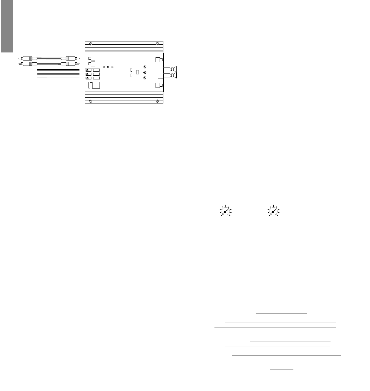
1 Connecting the remote wire
The remote wire is connected to the automatic antenna (aerial positive) output of
the head unit (radio). This is only activated if the head unit is switched ON. Thus the
amplifier is switched on and off with the head unit. The amplifier only turns on when
the battery- and ground cables are connected first.
2 Connecting the battery cable
Connect the +12 V cable to the positive terminal of the battery. Recommended cross
section: 10 mm
2
.
3 Connecting the ground cable
The ground cable should be connected to a central ground reference point (this is
located where the negative terminal of the battery is grounded at the metal body
of the vehicle), or to a bright bare-metal location on the vehicle chassis, i.e. an area
which has been cleaned of all paint residues.
4 Fuse
The input fuse provides protection against internal equipment fault, i.e. the system
must be additionally protected by a further line fuse located near the battery
(max. distance from the battery: 30 cm/ 12 inch). The fuse value of the amplifier
is 15 Ampere.
5 - 6 Signal inputs
The HXA 20/ HXA 20X have RCA connectors for cinch cables leading from the preamplifier outputs, the line outputs of the head units or the outputs of a pre-amplifier/ equalizer, e.g. HXE 100. These connectors are gold-plated in order to ensure
better signal transmission.
7 Green LED
When the green LED is on the amplifier is in operation.
8 Yellow LED
If the yellow LED is on there is a malfunction in the
amplifier or a impedance less than 2 Ohms at the loudspeakers output.
9 Red LED
The red LED turns on when the amplifier is overheated.
10 Selector switch for channels A and B
For switching the frequency crossover to highpass, lowpass or full range.
12 Switch for mono/ bridged and stereo
With this switch the channels A and B (16) can be bridged to mono. In this case the
total impedance of the connected speakers must be 4 ohm or higher. In stereo
mode the connected total impedance per channel can be 2 ohm or higher. In mono
mode the total input signal of both channels cannot be higher than 8.5 V !
14 - 15 Level adjustment for input sensitivity
These controls can be used to match the input sensitivity of the individual channnels A to B to the output voltage of the connected head unit. These controls are
not volume controls and are solely intended for the purpose of sensitivity trimmming. The adjustment range extends from 800 mV to 8.5 V.
16 Speaker connection terminal for channels A and B
ENGLISH
HXA 20
HXA20X
B
A
12
10
11
B
6
5
3
2
1
4
987
A
12
10
11
18
15
13
14
B
16
A
17
13
B
A
dB
0
-5
-10
-15
20 10050 200 50010
dB
0
-5
-10
-15
20 10050 20010
dB
0
-5
-10
-15
100 1K200 500 5K
dB
0
-5
-10
-15
20 10050 200 50010
dB
0
-5
-10
-15
100 1K200 500 5K
variabel
variabel
variabel
variabel
1K15 Hz
1K15 Hz500
10K2K Hz
1K15 Hz
10K2K Hz
Page 5

Integrated active crossover of HXA 20
The HXA 20 has an integrated active crossover of 90 Hz/ 12 dB Oct. The operating
mode can be selected with the switch 10.
Only for HXA 20X:
The HXA 20X has an active adjustable crossover with a variable frequency range
from 15 Hz to 5000 Hz. To adjust the frequencies use switch 10 ( HP, Full range, LP )
and switch 11 ( 15 Hz - 1 kHz and 1 kHz - 5 kHz ) and the potentiometer 13. The
residual signal is applied to RCA connectors 17 and 18 where it can be used to connnect an additional amplifier.
Example: If the chanels A and B are switched on Highpass 180 Hz, the frequencies
up to 180 Hz (Lowpass) are provided to the RCA connectors 17 and 18, e.g. to connnect a subwoofer amplifier
In general: Amplifier highpass channel A + B
=RCA output 17 lowpass channel A
=RCA output 18 lowpass channel B
Amplifier lowpass channel A + B
=RCA output 17 highpass channel A
=RCA output 18 highpass channel B
11 Switch for selecting the frequencies range
With this switch the adjustment range of the potentiometer 13 can be selected from
15 Hz to 1 kHz and from 1 kHz to 5 kHz.
13 Frequency controller
Frequency adjustment controller for the channels A+B .
17 - 18 RCA outputs
The RCA outputs supply the residual signal for connecting an additional amplifier.
Important information!
Scale to adjust the frequencies at potentiometer 13.
Important!
Do not ground speaker output terminal to vehicle chassis.This can destroy your
amplifier. Please pay attention to connect all loudspeakers in proper phase, i.e.
plus to plus and minus to minus.
Attention!
If you need further informations, please take a look at our web-site
www.audiotec-fischer.com
Technical Specifications:
Cont. Power rating at 4 Ohm p. channel 2x60/80 Watts RMS/Max. Power
Cont. Power rating at 2 Ohm p. channel 2x90/125 Watts RMS/Max. Power
Cont. Power bridged into a 4 Ohm load 1x180/250 Watts RMS Max. Power
Frequency Response 20Hz-20kHz,+/-0,2dB
Total Harmonic Distortion (THD) <0,009%
TIM Distortion <0,016%
Signal to Noise Ratio >100dB
Input Impedance 10kOhm
Input Sensitivity 800 mV-8,5V
Fuse 15 Ampere
Dimensions (HxWxD) in mm 31,5x185x236
Weight net 1,8 kgs
HXA 20 Switchable Frequency Crossover Highpass/Lowpass 90Hz
and Full Range
HXA 20X Adjustable Crossover Frequency range 15Hz-5000Hz HP/LP
Switch 11 at Position
15kHz - 1kHz
Switch 11 at Position
1kHz - 5kHz
AUDIOTEC FISCHER GMBH
Gewerbegebiet Lake II · Huenegraeben 26 · D-57392 Schmallenberg
Tel.: ++49 2972 9788 0 · Fax: ++49 2972 9788 88
E-mail: info@audiotec-fischer.com · Internet: www.audiotec-fischer.com
110
160
80
55
32
250
450
15
1K
Hz
2,2
1,8
2,7
1,5
1,3
3,3
4K
1K
5K
Hz
 Loading...