

Page 1
deutsch / english
DSP MINI
Digitaler High-Res 6-Kanal Signalprozessor mit
96 kHz / 24 Bit Signalweg
Digital High-Res 6-channel signal processor with
96 kHz / 24 Bit signal path
Page 2

Herzlichen Glückwunsch!
Sehr geehrter Kunde,
Wir gratulieren Ihnen zum Kauf dieses hochwertigen HELIX-Signalprozessors.
Audiotec Fischer setzt mit dem HELIX DSP MINI
neue Maßstäbe im Bereich der Signalprozessor-
technik. Dabei protieren Sie als Kunde direkt von
unserer nahezu 30-jährigen Erfahrung in der For-
schung und Entwicklung von Audiokomponenten.
Allgemeine Hinweise
Allgemeines zum Einbau von HELIX-Komponenten
Um alle Möglichkeiten des Produktes optimal ausschöpfen zu können, lesen Sie bitte sorgfältig die
nachfolgenden Installationshinweise. Wir garantieren, dass jedes Gerät vor Versand auf seinen einwandfreien Zustand überprüft wurde.
Vor Beginn der Installation unterbrechen Sie
den Minusanschluss der Autobatterie.
Wir empfehlen Ihnen, die Installation von einem
Einbauspezialisten vornehmen zu lassen, da der
Nachweis eines fachgerechten Einbaus und Anschlusses des Gerätes Voraussetzung für die Garantieleistungen sind.
Installieren Sie Ihren HELIX DSP MINI an einer
trockenen Stelle im Auto und vergewissern Sie
sich, dass der Signalprozessor am Montageort genügend Kühlung erhält. Montieren Sie das Gerät
nicht in zu kleine, abgeschlossene Gehäuse ohne
Luftzirkulation oder in der Nähe von wärmeabstrahlenden Teilen oder elektronischen Steuerungen des
Fahrzeuges. Im Sinne der Unfallsicherheit muss
der Signalprozessor professionell befestigt werden.
Dieses geschieht über Schrauben, die in eine Mon-
tageäche eingeschraubt werden, die wiederum
genügend Halt bieten muss.
Bevor Sie die Schrauben im Montagefeld befestigen, vergewissern Sie sich, dass keine elektrischen
Kabel und Komponenten, hydraulische Bremslei-
tungen, der Benzintank etc. dahinter verborgen
2
Dieser Prozessor wurde von uns nach neuesten
technischen Erkenntnissen entwickelt und zeichnet
sich durch hervorragende Verarbeitung und eine
überzeugende Anwendung ausgereifter Technologien aus.
Viel Freude an diesem Produkt wünscht Ihnen das
Team von
AUDIOTEC FISCHER
sind. Diese könnten sonst beschädigt werden. Achten Sie bitte darauf, dass sich solche Teile auch in
der doppelten Wandverkleidung verbergen können.
Allgemeines zum Anschluss des HELIX
DSP MINI Signalprozessors
Der Signalprozessor darf nur in Kraftfahrzeuge ein-
gebaut werden, die den 12 V-Minuspol an Masse
haben. Bei anderen Systemen können der HELIX
Signalprozessor und die elektrische Anlage des Kfz
beschädigt werden. Die Plusleitung für die gesamte
Anlage sollte in einem Abstand von max. 30 cm von
der Batterie mit einer Hauptsicherung abgesichert
werden. Der Wert der Sicherung errechnet sich aus
der maximalen Stromaufnahme der Car-Hi Anlage.
Verwenden Sie zum Anschluss des Signalprozessors an die Stromversorgung des Fahrzeugs
ausschließlich den beiliegenden Anschlussstecker!
Die Kabelverbindungen müssen so verlegt sein,
dass keine Klemm-, Quetsch- oder Bruchgefahr besteht. Bei scharfen Kanten (Blechdurchführungen)
müssen alle Kabel gegen Durchscheuern gepols-
tert sein. Ferner darf das Versorgungskabel niemals
mit Zuleitungen zu Vorrichtungen des Kfz (Lüfter-
motoren, Brandkontrollmodulen, Benzinleitungen
etc.) verlegt werden.
Page 3
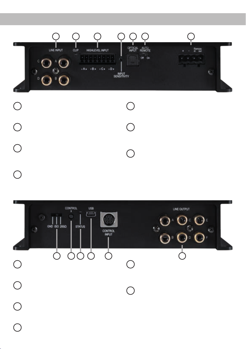
Anschluss- und Bedienelemente
1 32 5 6 74
Line Input
1
Cinch-Eingänge zum Anschluss eines
Vorverstärkersignals.
Clipping LED
2
Diese LED leuchtet rot, wenn einer der
Analogeingänge übersteuert wird.
.
Highlevel Input
3
Hochpegel-Lautsprechereingang zum
Anschluss von Werksradios oder Radios
ohne Vorverstärkerausgänge.
Input Sensitivity
4
Regler zum Einstellen der
Eingangsempndlichkeit des Line und
Highlevel Inputs.
8 9 10 11 12 13
Masseschalter
8
Deniert die Verbindung der Masse zwischen
Signaleingang und Signalausgang.
Control Taster
9
Dient zum Umschalten der Sound Setups
oder zum Resetten des Gerätes.
Status LED
10
Die Status LED zeigt den Betriebszustand
und den ausgewählten Speicherbereich an.
5
Optischer Eingang im SPDIF-Format für
6
Dient zum Aktivieren bzw. Deaktivieren
7
Zum Anschluss an die Bordnetzspannung
12
Multifunktionsanschluss - dient zum
13
Vorverstärkerausgänge zum Anschluss des /
Optical Input
digitale Stereosignale.
Auto Remote
der automatischen Einschaltung des
Signalprozessors.
Power Input
mit einem zusätzlichen Remote-Ein- und
Ausgang. Der Remote-Ausgang muss
in jedem Fall zur Einschaltung weiterer
Verstärker genutzt werden.
Control Input
Anschluss einer Fernbedienung und
weiterem HELIX Zubehör.
Line Output
der Verstärker/s. Zur Einschaltung eines
angeschlossenen Verstärkers muss der
Remote-Ausgang verwendet werden.
USB Eingang
11
Dient zum Anschluss an den Computer.
3
Page 4

Inbetriebnahme und Funktionen
Line Input
1
4-Kanal Vorverstärkereingang zum Anschluss von
Signalquellen, z.B. Radios. Die Eingangsempndlichkeit ist für alle Kanäle ab Werk auf 4 Volt ein-
gestellt (Linksanschlag). Es ist jedoch möglich, die
Eingangsempndlichkeit zwischen 2 und 4 Volt zu
variieren.
Clipping LED
2
Diese LED leuchtet rot, wenn einer der vier Line
Inputs oder Highlevel Inputs übersteuert wird. Die
LED hat keine Funktion bei Ansteuerung über den
Digitaleingang. Sofern diese LED aueuchtet, sollte
die Eingangsempndlichkeit über den Drehregler
(Punkt 4; Input Sensitivity) abgesenkt werden, bis
die LED erlischt.
Highlevel Input
3
4-Kanal Hochpegel-Lautsprechereingang. Mit Hilfe dieses Eingangs kann der Signalprozessor direkt an die Lautsprecherausgänge eines Werks-/
Nachrüstradios oder eines Werksverstärkers angeschlossen werden, sofern dieses / dieser nicht über
Vorverstärkerausgänge verfügt. Die Eingangsempndlichkeit ist für alle Kanäle ab Werk auf 11 Volt
eingestellt (Linksanschlag). Es ist jedoch möglich,
die Eingangsempndlichkeit mit dem Regler 4 (Input Sensitivity) zwischen 5 - 11 Volt zu variieren.
Achtung: Verwenden Sie zum Anschluss aus-
schließlich die mitgelieferten Stecker mit integrierten Schraubklemmen.
Achtung: Der Highlevel- und der Vorverstärker-
signaleingang eines einzelnen Kanals darf nicht
gleichzeitig genutzt werden, da dies zu Schäden
an ihrem Autoradio führen kann. Es ist aber zuläs-
sig, an einem Kanal den Highlevel- und an einem
anderen Kanal den Vorverstärkersignaleingang zu
verwenden.
Input Sensitivity
4
Mit Hilfe dieses Reglers kann die Eingangsemp-
ndlichkeit der Kanäle an die Ausgangsspannung
des angeschlossenen Steuergerätes angepasst
werden. Dieser Regler ist kein Lautstärkeregler,
sondern dient nur der Anpassung. Die Einstellung
dieses Reglers beeinusst nicht den optischen Eingang. Die Regelbereiche liegen bei 2 - 4 Volt für den
Cinch-Eingang (Line Input) und 5 - 11 Volt für den
Hochpegel-Lautsprechereingang (Highlevel Input).
4
Achtung: Es ist zwingend notwendig, die Eingangs-
empndlichkeit des DSP MINI an die Signalquelle
anzupassen, um Schäden am Signalprozessor zu
vermeiden.
Hinweis: Werkseitig ist die Eingangsempndlich-
keit auf Linksanschlag justiert. Dies ist in nahezu
allen Fällen bereits die optimale Einstellung.
Optical Input
5
Optischer Eingang im SPDIF-Format für den Anschluss an Signalquellen mit digitalem Ausgang.
Die „Sampling Rate“ dieses Eingangs muss zwischen 12 - 96 kHz liegen. Das Eingangssignal wird
automatisch an die interne Abtastrate angepasst.
Um diesen Eingang zu aktivieren und in der Lautstärke regeln zu können, wird eine optional erhältliche Fernbedienung empfohlen.
Hinweis: Es können ausschließlich Stereosignale
und keine MP3- oder Dolby-codierten Daten verarbeitet werden!
Hinweis: Eine gleichzeitige Verwendung des op-
tischen Eingangs zusammen mit den HochpegelSignaleingängen oder den Vorverstärker-Signalein-
gängen ist möglich.
Auto Remote
6
Die Einschaltung des Verstärkers erfolgt automatisch bei Ansteuerung über die Hochpegel-Lautsprechereingänge (Highlevel Input) oder sobald ein
Remote-Signal am Remote-Eingang (Remote in)
anliegt.
Mit Hilfe des Auto Remote-Schalters kann die automatische Einschaltung über die Hochpegel-Laut-
sprechereingänge aktiviert bzw. deaktiviert werden.
Die Deaktivierung (Auto Remote = Off) sollte vorge-
nommen werden, wenn es beispielsweise zu Störgeräuschen beim Ein- und Ausschalten des Signalprozessors kommt.
Hinweis: Werkseitig ist die automatische Einschaltung über den Hochpegel-Lautsprechereingang des
DSP MINI aktiviert (Auto Remote = On).
Hinweis: Wird die automatische Einschaltung des
Signalprozessors deaktiviert, muss der Remote-
Eingang belegt werden. Eine automatische Einschaltung über den Hochpegel-Lautsprechereingang ist dann nicht mehr möglich.
Page 5

Power Input
7
Diese Buchse dient zum Anschluss des Signalpro-
zessors an die Stromversorgung des Fahrzeuges
sowie für die Remote-Ein- und Ausgänge.
Sofern die Hochpegel-Lautsprechereingänge verwendet werden, muss der Remote-Eingang (Remote in) nicht belegt werden.
Der Remote-Ausgang (Remote out) dient zum prozessorgesteuerten Einschalten der am Line Output
angeschlossenen Verstärker. Schließen Sie den
Remote-Ausgang an die Remote-Eingänge Ihrer
Verstärker an. Um Störgeräusche beim Ein- und
Ausschalten zu vermeiden, sollte der Remote-Aus-
gang in jedem Fall belegt werden.
Dieser Ausgang aktiviert sich automatisch, sobald
der Bootvorgang des DSP abgeschlossen ist. Zudem wird dieser Ausgang bei aktiviertem „Power
Save Mode“ und bei Betriebssoftware-Updates ab-
geschaltet.
Achtung: Verwenden Sie ausschließlich den mitge-
lieferten Stecker mit integrierten Schraubklemmen.
Wichtig: Verwenden Sie niemals ein anderes
Signal als den Remote-Ausgang, um angeschlossene Verstärker einzuschalten!
Masseschalter
8
Beim HELIX DSP MINI ist die Masse der Signaleingänge galvanisch von der Masse der Signalausgänge getrennt. Dies ist in den meisten Fahrzeugen
die beste Option, um Störgeräusche wie z.B. von
der Lichtmaschine zu unterbinden. Allerdings gibt
es auch Fälle, wo die Massen der Eingänge mit den
Ausgängen direkt „hart“ oder über einen 200 Ohm
Widerstand „weich“ verbunden werden müssen.
Der Masseschalter hat drei Positionen:
- Mittelstellung: Massen galvanisch getrennt.
- Linksanschlag: Massen „hart“ zusammengeschaltet.
- Rechtsanschlag: Massen „weich“ gekoppelt.
Control Taster
9
Der DSP MINI bietet 10 interne Speicherplätze für
Sound Setups. Mit Hilfe des Control Tasters lässt
sich zwischen zwei Speicherplätzen umschalten.
Diese können im DSP PC-Tool festgelegt werden.
Hinweis: Werkseitig sind die Speicherbereiche
eins und zwei eingestellt. Zum manuellen Umschalten zwischen den zwei Setups muss der
Control Taster eine Sekunde lang gedrückt wer-
den. Der Umschaltvorgang wird durch einmaliges
rotes Blinken der Status LED angezeigt. Um zwischen allen internen Speicherplätzen umschalten
zu können, wird die optional erhältliche DisplayFernbedienung DIRECTOR empfohlen. Wird der
Taster länger als fünf Sekunden gedrückt, so
wird das Gerät resettet und der gesamte interne
Speicher gelöscht! Anschließend wird dies durch
ein durchgehendes rotes Leuchten und grünes
schnelles Dauerblinken der Status LED angezeigt.
Achtung: Nach dem Resetten des Gerätes kann
der HELIX DSP MINI keine Audiosignale mehr wiedergeben, bis ein neues Sound Setup eingespielt
wurde.
10
Status LED
Die Status LED zeigt den Betriebszustand des
Signalprozessors und dessen Speichers an.
Grün: DSP eingeschaltet und betriebsbereit.
Orange: Power Save Modus aktiv.
Rot: Protection Mode aktiv. Dieser kann unterschiedliche Ursachen haben. Der DSP MINI ist mit
Schutzschaltungen gegen Über- und Unterspannung sowie Überhitzung ausgestattet. Prüfen Sie
in diesem Fall alle Anschlüsse auf Fehler, wie z.B.
Kurzschlüsse oder fehlerhafte Verbindungen. Ist die
Sicherheitsschaltung der Temperaturüberwachung
aktiv, wird der Remote-Ausgang sowie die Signalausgabe abgeschaltet, bis ein sicherer Betrieb wieder gewährleistet werden kann.
Rot / grün langsam blinkend: Keine Betriebssoft-
ware auf dem DSP installiert. Verbinden Sie den
Signalprozessor mit der DSP PC-Tool Software und
bestätigen das automatische Update der Betriebs-
software. Die aktuellste Version des DSP PC-Tools
nden Sie auf www.audiotec-scher.com.
Rot / grün schnell blinkend: Aktuell ausgewählter
Sound Setup-Speicherplatz ist leer. Ein neues DSP
Setup muss über die DSP PC-Tool Software eingespielt werden oder schalten Sie auf einen Speicher-
platz mit vorhandenem Sound Setup um.
11
USB Eingang
Mit Hilfe dieses Eingangs wird der HELIX DSP MINI
über das beiliegende Kabel mit dem Compu-
ter verbunden und kann anschließend über das
DSP PC-Tool konguriert werden.
Hinweis: Es können keine USB Speichermedien
an den Signalprozessor angeschlossen werden.
5
Page 6

Inbetriebnahme und Funktionen
12
Control Input
Dieser Multifunktionseingang dient zum Anschluss
von HELIX Zubehörprodukten, wie beispielsweise
einer Fernbedienung, mit deren Hilfe diverse Funk-
tionen des Signalprozessors gesteuert werden können. Die Funktionalität muss je nach Typ der Fern-
bedienung zuerst im „Device Conguration Menu“
der DSP PC-Tool Software oder an der Fernbedie-
nung selbst konguriert werden.
Einbau und Installation
Der HELIX DSP MINI wird wie nachfolgend beschrieben an das Autoradio angeschlossen.
Achtung: Für die Durchführung der nachfolgenden
Schritte werden Spezialwerkzeuge und Fachwissen
benötigt. Um Anschlussfehler und Beschädigungen
zu vermeiden, fragen Sie im Zweifelsfall Ihren Einbauspezialisten und beachten Sie zwingend die
allgemeinen Anschluss- und Einbauhinweise (siehe
Seite 2).
1. Anschluss der Vorverstärkereingänge
Diese Eingänge (Line Input) können mit entsprechenden Kabeln (RCA / Cinch-Kabel) an
die Vorverstärker- / Lowlevel- / Cinch-Ausgänge des Radios angeschlossen werden. Im Signalprozessor lassen sich die Signaleingänge
über die DSP PC-Tool Software frei den Vorverstärkerausgängen (Line Output) zuweisen. Die
Einschaltautomatik des Signalprozessors funk-
tioniert bei den Vorverstärkereingängen nicht,
so dass der Remote-Eingang zwingend belegt
werden muss.
Achtung: Der Highlevel- und der Vorverstär-
kersignaleingang eines einzelnen Kanals darf
nicht gleichzeitig genutzt werden, da dies zu
Schäden an ihrem Autoradio führen kann. Es ist
aber zulässig, an einem Kanal den High levelund an einem anderen Kanal den Vorverstärkersignaleingang zu verwenden.
6
13
Line Output
6-Kanal Vorverstärkerausgang zum Anschluss von
Verstärkern. Die maximale Ausgangsspannung beträgt 4 Volt. Wenn Sie diesen Ausgang verwenden,
ist es zwingend erforderlich den Remote-Ausgang
des Power Inputs zum Einschalten des / der an den
Line Output angeschlossenen Verstärker zu benut-
zen, da ansonsten Störsignale auftreten können.
Der Remote-Ausgang schaltet sich automatisch
während des „Power Save Mode“ sowie bei einem
Software-Update ab. Die Ausgänge können in der
DSP PC-Tool Software den Eingängen beliebig zugeordnet werden.
2. Anschluss der Highlevel-Lautsprechereingänge
Die Hochpegel-Lautsprechereingänge können direkt mit den Lautsprecherausgängen
des Werks- bzw. Nachrüstradios mit Hilfe entsprechender Kabel (Lautsprecherkabel mit
max. 1 mm² Querschnitt) verbunden werden.
Sollten Sie ein normales Werksradio anschließen, empfehlen wir folgende Kanalbelegung:
Kanal A = Vorne links
Kanal B = Vorne rechts
Kanal C = Hinten links
Kanal D = Hinten rechts
Dabei müssen nicht zwingend alle Eingänge belegt werden. Werden nur zwei Kanäle
belegt, empfehlen wir die Kanäle A und B zu
verwenden. Achten Sie bitte auf eine korrekte
Polung! Wenn Sie einen oder mehrere An-
schlüsse verpolen, kann dadurch die Funktion
des Signalprozessors beeinträchtigt werden.
Bei Verwendung dieses Eingangs muss der
Remote-Eingang nicht belegt werden, da sich
der Signalprozessor automatisch einschaltet,
sobald ein Lautsprechersignal anliegt.
3. Anschluss einer digitalen Signalquelle
Sofern Sie über eine Signalquelle mit optischem
Digitalausgang verfügen, kann diese an den
Signalprozessor angeschlossen werden. Der
HELIX DSP MINI ist werkseitig so konguriert,
dass automatisch auf den Digitaleingang umgeschaltet wird, wenn dort ein Audiosignal anliegt.
Page 7

Diese Funktion kann über die DSP PC-Tool
Software deaktiviert bzw. auf einen manuellen
Modus (in Verbindung mit einer optional erhält-
lichen Fernbedienung) geändert werden.
Die Einschaltautomatik des Signalprozessors
funktioniert bei Verwendung des Digitaleingangs nicht, so dass der Remote-Eingang des
Power Inputs zwingend belegt werden muss.
Eine gleichzeitige Nutzung des Digitaleingangs
sowie der Hochpegel- oder der Vorverstärkersignaleingänge ist möglich.
Wichtig: Das digitale Audiosignal einer Quelle
ist üblicherweise nicht lautstärkegeregelt. Das
bedeutet, dass an den Signalausgängen des
HELIX DSP MINI der volle Pegel anliegt und die
angeschlossenen Verstärker voll ausgesteuert
werden. Dies kann im Extremfall die Lautspre-
cher zerstören. Wir raten deshalb dringend
dazu, eine optionale Fernbedienung zur Einstellung der Lautstärke der digitalen Signalein-
gänge zu verwenden!
Hinweis: Der HELIX DSP MINI kann nur unkomprimierte, digitale Stereo PCM-Signale mit
einer Abtastrate zwischen 12 kHz und 96 kHz
verarbeiten. Es können keine MP3- oder Dolbycodierten Daten verarbeitet werden, sondern
ausschließlich Stereosignale.
4. Einstellung der Eingangsempndlichkeit
Achtung: Es ist zwingend notwendig die
Eingangsempndlichkeit des DSP MINI an
die Signalquelle anzupassen, um Schäden
am Signalprozessor zu vermeiden.
Um die Eingangsempndlichkeit zu verändern,
verwenden Sie den Drehregler 4 (Punkt 4,
Seite 4; Input Sensitivity). Werkseitig ist die
Eingangsempndlichkeit auf Linksanschlag justiert. Dies ist in nahezu allen Fällen bereits die
optimale Einstellung. Nur wenn die Signalquelle
einen zu kleinen Maximalpegel liefert, sollte die
Eingangsempndlichkeit mit Hilfe des Drehreglers vorsichtig angehoben werden. Die Einstellung dieses Drehreglers beeinusst sowohl die
Vorverstärkereingänge als auch die Hochpegel-
Eingänge!
Zur Anpassung der Eingangsempndlichkeit
führen Sie bitte die folgenden Schritte durch:
1. Schließen Sie während dieser Prozedur keinen Verstärker an die Ausgänge des Signal-
prozessors.
2. Schalten Sie den Signalprozessor ein.
3. Drehen Sie die Lautstärke Ihres Radios auf
90 % der Gesamtlautstärke und spielen Sie
über das CD-Laufwerk ein 1 kHz Testsignal
(Vollaussteuerung 0 dB) ab.
4. Sollte die Clipping LED bereits leuchten,
verringern Sie mit Hilfe des Drehreglers
(Punkt 4, Seite 4; Input Sensitivity) die Eingangsempndlichkeit, bis die Clipping LED
erlischt.
5. Erhöhen Sie die Eingangsempndlichkeit
durch Rechtsdrehung bis die Clipping LED
aueuchtet. Drehen Sie nun den Drehregler
gegen den Uhrzeigersinn bis die Clipping
LED wieder erlischt.
5. Anschluss der Stromversorgung
Vor dem Anschluss des +12 V Versorgungs-
kabels an das Bordnetz muss die Autobatterie abgeklemmt werden.
Schließen Sie die Stromversorgung aus-
schließlich über den mitgelieferten Stecker mit
Schraubklemmen an. Achten Sie unbedingt auf
eine korrekte Polarität.
Die Masseleitung muss an einer nicht isolierten
Stelle mit dem Kfz-Chassis verbunden werden.
Ein nicht ausreichender Massekontakt führt zu
unerwünschten Störgeräuschen und Fehlfunktionen.
Die Plusleitung wird entweder direkt an den
Pluspol der Batterie oder an einen Stromverteiler angeschlossen, der mit dem Pluspol der
Batterie verbunden ist. Die Stromaufnahme des
HELIX DSP MINI ist mit ca. 400 mA zwar sehr
gering, trotzdem sollten Kabel mit min. 1 mm²
Querschnitt für die Spannungsversorgung ver-
wendet werden.
6. Anschluss des Remote-Eingangs
Der Remote-Eingang des Power Inputs muss
mit dem Remote-Ausgang des Steuergeräts
(Radio) verbunden sein, sofern die Vorverstärkereingänge (Line Input) oder der Digitaleingang (Optical Input) des Signalprozessors als
Signaleingänge / Signaleingang genutzt wer-
den / wird. Es wird dringend davon abgeraten,
den Remote-Eingang des Signalprozessors
über das Zündungsplus des Fahrzeugs zu
7
Page 8

Einbau und Installation
steuern, um Störgeräusche beim Ein- und Aus-
schalten zu vermeiden.
Bei Verwendung des Hochpegel-Lautsprecher-
eingangs ( Highlevel Input) muss der Remote-
Eingang nicht belegt werden, sofern das angeschlossene Radio über BTL-Ausgangsstufen
verfügt.
7. Konguration des Remote-Eingangs
Die Einschaltung des HELIX DSP MINI erfolgt
automatisch bei Ansteuerung über die Hochpegel-Lautsprechereingänge (High level Input)
oder sobald ein Remote-Signal am RemoteEingang anliegt. Mit Hilfe des Auto RemoteSchalters (Seite 4, Punkt 6; Auto Remote)
kann die automatische Einschaltung deaktiviert
werden (Auto Remote = Off). Dies sollte vorge-
nommen werden, wenn es beispielsweise zu
Störgeräuschen beim Ein- und Ausschalten des
Signal prozessors kommt.
Hinweis: Wird die automatische Einschaltung
des Signalprozessors deaktiviert, muss der
Remote-Eingang belegt werden. Eine automatische Einschaltung über den HochpegelLautsprecher eingang ist dann nicht mehr möglich.
Hinweis: Werkseitig ist die automatische Einschaltung über den Hochpegel-Lautsprecher-
eingang des DSP MINI aktiviert.
8. Konguration des DSPs
Es wird dringend empfohlen, vor der ersten
Inbetriebnahme die grundlegenden Einstellungen im DSP mit Hilfe der DSP PC-Tool
Software vorzunehmen.
Eine Missachtung kann zur Zerstörung der
angeschlossenen Verstärker / der Lautsprecher führen. Informationen zum Anschluss des
Signalprozessors an einen PC nden Sie auf
Seite 9.
9. Anschluss des Remote-Ausgangs
Dieser Ausgang dient dazu, einen am Line Out-
put angeschlossenen Verstärker mit einem Re-
mote-Signal zu versorgen. Bitte verwenden Sie
ausschließlich dieses Signal zur Einschaltung
externer Verstärker, um Ein- und Ausschaltgeräusche zu vermeiden.
8
Page 9

Anschluss an den Computer
Der HELIX DSP MINI kann mit Hilfe der
DSP PC-Tool Software frei konguriert werden. Die
Software stellt alle Funktionen übersichtlich und
bedienerfreundlich zur Verfügung, so dass Sie diese individuell einstellen können. Dabei können alle
sechs DSP Kanäle separat eingestellt werden.
Bevor Sie den HELIX DSP MINI das erste Mal an
einen Computer anschließen, gehen Sie auf unsere
Homepage und laden die aktuellste Software Ver-
sion des DSP PC-Tools herunter. Es ist ratsam, regelmäßig nach Updates der Software zu schauen,
damit das Gerät immer auf dem aktuellsten Stand
ist.
Die Software sowie die dazugehörige Bedienungsanleitung nden Sie auf www.audiotec-scher.com.
Es wird dringend empfohlen, die Bedienungsanlei-
tung der Software (Sound Tuning Magazin) vor der
ersten Benutzung durchzulesen, um Komplikati-
onen und Fehler zu vermeiden.
Wichtig: Stellen Sie sicher, dass der
HELIX DSP MINI bei der ersten Installation der
Software noch nicht an den PC angeschlossen ist.
Verbinden Sie diesen erst, wenn die Software samt
der USB-Treiber vollständig installiert ist!
Im folgenden Abschnitt lesen Sie die wichtigsten
Schritte zum Anschluss und der ersten Inbetriebnahme:
1. Laden Sie die DSP PC-Tool Software unter
www.audiotec-scher.com herunter und installieren diese auf ihrem Computer.
2. Schließen Sie danach den DSP MINI mit dem
beiliegenden USB-Kabel an den Computer an.
Wenn Sie längere Distanzen zu überbrücken
haben, verwenden Sie bitte eine aktive USBVerlängerung mit integriertem Repeater und
kein passives USB-Kabel.
3. Schalten Sie erst den Signalprozessor ein und
starten Sie anschließend die Software. Sofern
die Betriebssoftware des DSPs nicht mehr aktuell ist, wird diese automatisch aktualisiert.
4. Nun können Sie den HELIX DSP MINI mithilfe
der DSP PC-Tool Software frei kongurieren.
Nützliche Hinweise zur korrekten Einstellung
entnehmen Sie z.B. unserem „Sound Tuning
Magazin“, welches auf unserer Webseite zum
Download bereit steht.
Achtung: Es wird dringend empfohlen, vor der
ersten Inbetriebnahme die Lautstärke am Radio
auf Minimum zu drehen und an die Vorverstärker-
ausgänge des DSP MINI noch nichts anzuschließen, bis die grundlegenden Einstellungen im Si-
gnalprozessor vorgenommen wurden. Speziell bei
Verwendung in vollaktiven Systemen besteht sonst
Zerstörungsgefahr für die Lautsprecher.
9
Page 10

Kongurationshinweise für die DSP-Soundeffekte
Der HELIX DSP MINI bietet einzigartige DSPSound effekte wie das „Augmented Bass Processing“, den „StageXpander“, den „RealCenter“ und
noch mehr.
Um jedoch in den Genuss aller DSP-Soundeffekte
zu kommen, müssen bei der Hard- und Softwarekonguration bestimmte Einstellungen vorgenommen werden.
Hinweise für das Center Processing mit seiner
RealCenter- und ClarityXpander-Funktion
Um die RealCenter- und ClarityXpander-Funktion für
einen Center-Lautsprecher nutzen zu können, müssen folgende Schritte durchgeführt werden:
1. Sie benötigen mindestens ein linkes und ein
rechtes analoges oder digitales Eingangssignal.
2. Öffnen Sie das IO-Menü im DSP PC-Tool. Routen Sie das linke und das rechte analoge oder
digitale Eingangssignal (kein Summensignal) auf
die Ausgangskanäle A und B (siehe Beispiel im
nachfolgenden Bild). Es spielt dabei keine Rolle
ob der Ausgangskanal als Front-, Rear-, Center-
Kanal etc. deniert ist.
Hinweis: Die beste Performance erzielen Sie,
wenn das Eingangssignal ein Fullrange-Signal
ist.
3. Bilden Sie aus den gleichen zwei Eingangssignalen ein Summensignal und routen dies auf
den Ausgangskanal E. Dieser sollte als „Center
Full“ deniert werden.
Hinweis: Das Center Processing wird ausschließlich auf den Ausgangskanal E angewendet.
Hinweise für das Augmented Bass Processing
mit seiner Dynamic Bass Enhancement- und
SubXpander-Funktion
Auch für das Augmented Bass Processing müssen
bestimmte Einstellungen vorgenommen werden,
um dessen Soundeffekte anwenden zu können.
1. Sie benötigen mindestens ein linkes und ein
rechtes analoges oder digitales Eingangssignal.
Hinweis: Wenn Sie den analogen Signaleingang
verwenden, erzielen Sie die beste Performance
bei Belegung aller vier Eingänge.
2. Öffnen Sie das IO-Menü im DSP PC-Tool. Bilden Sie nun ein Summensignal aus allen linken
und rechten analogen oder digitalen Eingangssignalen und routen dies auf den Ausgangskanal F.
3. Wiederholen Sie das Routing für alle genutzten
Routing-Matrizen.
4. Wechseln Sie nun in das FX-Menü und aktivie-
ren den gewünschten Soundeffekt durch setzen
eines Hakens.
4. Wiederholen Sie die Schritte zwei und drei für
alle genutzten Routing-Matrizen.
5. Wechseln Sie nun in das FX-Menü und aktivie-
ren den gewünschten Soundeffekt durch setzen
eines Hakens.
10
Hinweis: Das Augmented Bass Processing wird
ausschließlich auf den Ausgangskanal F angewendet.
Page 11

Einbau einer HELIX Extension Card
Der HELIX DSP MINI kann durch die Montage einer
HELIX Extension Card (HEC) um weitere Schnittstellen wie beispielsweise einem Bluetooth
®
Audio
Streaming Modul, einer High Resolution Audio USB
Soundkarte etc. erweitert werden.
Zur Montage einer HEC muss das Seitenblech des
DSP MINI demontiert und gegen das der HEC beiliegende Seitenblech ausgetauscht werden.
Achtung: Installieren Sie ausschließlich für
den DSP MINI vorgesehene HEC Module an der
dafür vorgesehenen Position. Die Benutzung
eines nicht für das Gerät spezizierten HEC Moduls oder eine Installation an einer nicht dafür
vorgesehenen Position im Gerät kann zu Schäden am HEC Modul, dem Signalprozessor, des
Radios oder anderen angeschlossenen Geräten
führen.
Im folgenden Abschnitt nun die wichtigsten Schritte
zum Einbau und der ersten Inbetriebnahme eines
HEC Moduls:
1. Ziehen Sie zunächst alle Steckverbindungen
vom Gerät ab.
2. Lösen Sie die fünf Schrauben (eine Inbus- und
vier Kreuzschlitzschrauben) des Seitenblechs
der Geräteseite mit dem USB Eingang und entfernen dieses.
3. Ziehen Sie nun das Bodenblech zur Seite he-
raus.
4. Bereiten Sie das Modul für den Einbau in das
Gerät vor. Informationen dazu entnehmen Sie
bitte der Bedienungsanleitung des jeweiligen
HEC Moduls.
5. Stecken Sie das HEC Modul in den im Gerät
vorgesehenen Sockel (siehe Markierung im
nachfolgenden Bild).
6. Achten Sie auf den richtigen Sitz des HEC Moduls und darauf, dass alle Kontaktstifte vollständig im Sockel stecken.
7. Schieben Sie das Bodenblech wieder seitlich in
das Gehäuse des Signalprozessors. Anschließend befestigen Sie das neue, dem HEC Modul
beiliegende Seitenblech mit der Inbus- und den
Kreuzschlitzschrauben.
8. Verschrauben Sie das HEC Modul mit dem
Seitenblech. Genaue Informationen zur Befestigung entnehmen Sie bitte der Bedienungsanleitung des jeweiligen Moduls.
9. Schließen Sie alle Steckverbindungen wieder
an das Gerät an.
10. Schalten Sie den Signalprozessor ein. Das in-
stallierte HEC Modul wird nun automatisch vom
Gerät erkannt und die Status LED des HEC Moduls leuchtet grün.
11. Das Modul kann nun in der DSP PC-Tool Soft-
ware konguriert werden.
11
Page 12

Spezielle Features des HELIX DSP MINI
96 kHz Abtastrate
Der HELIX DSP MINI bietet eine Signalverarbeitung
mit einer doppelten Abtastrate von 96 kHz. Dadurch
ist die Audiobandbreite nicht wie üblich auf 22 kHz
begrenzt, sondern erlaubt einen ausgedehnten
Frequenzgang bis über 40 kHz. Die höhere Abtastrate stellt aber deutlich höhere Anforderungen an
den DSP selbst, denn die Anzahl der möglichen Re-
chenoperationen wird bei einer Verdoppelung der
Abtastrate auf die Hälfte reduziert. Erst der Einsatz
der allerneuesten Chipgeneration ermöglicht es,
trotz gesteigertem Funktionsumfang die Abtastrate
auf 96 kHz anzuheben.
ACO - Advanced 32 Bit CoProcessor
Der HELIX DSP MINI verwendet für alle internen
wie auch externen Steuerungs- und Kommunika-
tionsaufgaben einen besonders leistungsstarken
32 Bit CoProcessor der neuesten Generation. Im
Gegensatz zum bisher verwendeten 8 Bit Prozessor ergeben sich daraus deutliche Geschwindig-
keitsvorteile nicht nur bei der Umschaltung zwischen verschiedenen Sound Setups sondern vor
allem auch in der Datenkommunikation mit unserer
DSP PC-Tool Software. Ein weiterer wesentlicher
Vorteil ist der integrierte, native Bootloader des
CoProcessors. Dieser ermöglicht Software-Upgrades aller Komponenten des DSPs, um beispielsweise den Mikrocontroller-gesteuerten ADEP.3Schaltkreis auch zukünftig auf Änderungen bei
Diagnosesystemen von Werksradios anpassen zu
können oder das Gerät um weitere Schnittstellen zu
erweitern. Darüber hinaus bietet der ACO dank des
neuen Flashspeichers Platz für 10 Sound Setups
anstelle der üblichen zwei.
Intelligenter Highlevel-Eingang ADEP.3
Moderne, ab Werk verbaute Autoradios werden
bezüglich der Diagnose der angeschlossenen Lautsprecher immer intelligenter. Speziell die neueste
Generation ist mit zusätzlichen Überwachungsfunktionen ausgestattet, sodass bei Anschluss eines zusätzlichen Signalporzessors Fehlermeldungen oder
gar Fehlfunktionen auftreten können. Der neue
ADEP.3-Schaltkreis (Advanced Diagnostics Error
Protection Generation 3) verhindert diese Probleme
ohne die Lautsprecherausgänge des Radios bei hohen Pegeln unnötig zu belasten.
Start-Stopfähigkeit
Das Netzteil im HELIX DSP MINI stellt die interne
Spannungsversorgung auch bei kurzfristigen Einbrüchen bis hinab zu 6 Volt sicher.
Damit ist gewährleistet, dass der HELIX DSP MINI
auch beim Motorstart voll funktionsfähig bleibt.
Power Save Modus
Der Power Save Modus ist in den Grundeinstellungen der DSP PC-Tool Software aktiviert. Er er-
laubt, die Leistungsaufnahme der an den Signal-
prozessor angeschlossenen Verstärker drastisch
zu reduzieren, wenn für länger als 60 Sek. kein
Eingangssignal anliegt. Es ist zu berücksichtigen,
dass heutzutage viele Fahrzeuge mit „CAN“ oder
ähnlichen internen Bussystemen ausgestattet sind,
die das Radio für den Anwender „unsichtbar“ noch
bis zu 45 Min. eingeschaltet lassen, selbst wenn
man zwischenzeitlich das Fahrzeug verlässt und
abgeschlossen hat. Sobald der „Power Save Mode“
aktiv ist, wird der Remote-Ausgang und damit die
angeschlossenen Verstärker abgeschaltet. Der
HELIX DSP MINI reaktiviert den Remote-Ausgang
innerhalb einer Sekunde, sobald wieder ein Musiksignal an einem seiner Eingänge anliegt. Es ist zudem möglich, über die DSP PC-Tool Software die
Abschaltverzögerung zu variieren bzw. den „Power
Save Mode“ komplett zu deaktivieren.
Automatic Digital Signal Detection
Die Umschaltung zwischen den analogen und dem
Digitaleingang erfolgt signalgesteuert. Sobald ein
Audiosignal am Optical Input detektiert wird, schaltet der Signalprozessor auf diesen Eingang um. In
der DSP PC-Tool Software kann diese Funktion
deaktiviert oder alternativ eine manuelle Steuerung über eine optional erhältliche Fernbedienung
gewählt werden.
12
Page 13

Technische Daten
Eingänge ......................................................................... 4 x Cinch
4 x Hochpegel-Lautsprechereingang
1 x Optisch SPDIF-Format (12 - 96 kHz)
1 x Remote In
Eingangsempndlichkeit .................................................. Cinch 2 - 4 Volt
Hochpegel 5 - 11 Volt
Ausgänge ........................................................................6 x Cinch
1 x Remote Out
Ausgangsspannung .........................................................4 Volt
Frequenzbereich..............................................................10 Hz - 44.000 Hz
DSP Auösung ................................................................64 Bit
DSP Rechenleistung .......................................................295 MHz (1,2 Mrd. MAC Operationen/Sekunde)
Abtastrate ........................................................................96 kHz
DSP Typ ..........................................................................Audio Signalprozessor
Signalwandler .................................................................. A/D: Asahi Kasei
D/A: Asahi Kasei
Signal- / Rauschabstand Digitaleingang..........................106 dB (A-bewertet)
Signal- / Rauschabstand Analogeingang.........................103 dB (A-bewertet)
Klirrfaktor (THD+N) Digitaleingang ..................................< 0,001 %
Klirrfaktor (THD+N) Analogeingang ................................. < 0,002 %
Intermodulationsverzerrungen Digitaleingang .................< 0,004 %
Intermodulationsverzerrungen Analogeingang ................< 0,004 %
Übersprechen ..................................................................> 90 dB
Betriebsspannung............................................................9,6 - 18 Volt (max. 5 Sek. bis hinab zu 6 Volt)
Stromaufnahme ...............................................................< 400 mA
Max. Remote-Ausgangsstrom .........................................500 mA
Zusätzliche Features .......................................................HEC Slot, Masseschalter, Control Input,
32 Bit CoProcessor, ADEP.3-Schaltkreis,
Auto Remote-Schalter
Abmessungen (H x B x T) ...............................................40 x 177 x 104 mm
Garantiehinweis
Die Garantieleistung entspricht der gesetzlichen
Regelung. Von der Garantieleistung ausgeschlossen sind Defekte und Schäden, die durch Überlastung oder unsachgemäße Behandlung entstanden
sind. Eine Rücksendung kann nur nach vorheriger
Absprache in der Originalverpackung, einer de-
taillierten Fehlerbeschreibung und einem gültigen
Kaufbeleg erfolgen.
Hinweis:
„Die Bluetooth® Wortmarke und die Logos sind eingetragene Warenzeichen der Bluetooth SIG, Inc. und jegliche Nutzung dieser Marken
durch die Audiotec Fischer GmbH geschieht unter Lizenz. Andere Handelsmarken und Handelsnamen gehören den jeweiligen Inhabern.“
Technische Änderungen und Irrtümer vorbehalten!
Für Schäden am Fahrzeug oder Gerätedefekte, her-
vorgerufen durch Bedienungsfehler des Gerätes,
können wir keine Haftung übernehmen. Dieses
Produkt ist mit einer CE-Kennzeichnung versehen.
Damit ist das Gerät für den Betrieb in Fahrzeugen
innerhalb der Europäischen Union (EU) zertiziert.
13
Page 14

Congratulations!
Dear Customer,
Congratulations on your purchase of this innovative
and high-qual ity HELIX product.
Thanks to more than 30 years of experience in
research and development of audio products the
HELIX DSP MINI sets new standards in the range
of digital signal processors.
General instructions
General installation instructions for HELIX
components
To prevent damage to the unit and possible injury,
read this manual carefully and follow all installation
instructions. This product has been checked for
proper function prior to shipping and is guaranteed
against manufacturing defects.
Before starting your installation, disconnect
the battery’s negative terminal to prevent
damage to the unit, re and / or risk of injury. For
a proper performance and to ensure full warranty
coverage, we strongly recommend to get this product installed by an authorized HELIX dealer.
Install your HELIX DSP MINI in a dry location with
sufcient air circulation for proper cooling of the
equipment. The signal processor should be secured
to a solid mounting surface using proper mounting
hardware. Before mounting, carefully examine the
area around and behind the proposed installation location to insure that there are no electrical
cables or components, hydraulic brake lines or any
part of the fuel tank located behind the mounting
surface. Failure to do so may result in unpredictable
damage to these components and possible costly
repairs to the vehicle.
We wish you many hours of enjoyment with your
new HELIX DSP MINI.
Yours,
AUDIOTEC FISCHER
General instruction for connecting the HELIX
DSP MINI signal processor
The HELIX DSP MINI signal processor may only be
installed in vehicles which have a 12 Volts negative
terminal connected to the chassis ground. Any other
system could cause damage to the signal processor
and the electrical system of the vehicle.
The positive cable from the battery for the entire
sound system should be provided with a main fuse
at a distance of max. 30 cm from the battery. The
value of the fuse is calculated from the maximum
total current draw of the car audio system.
Use only the provided connectors for connection of the HELIX DSP MINI. The use of other
connectors or cables can result in damage of
the signal processor, the head unit / radio or the
connected ampliers / loudspeakers!
Prior to installation, plan the wire routing to
avoid any possible damage to the wire harness.
All cabling should be protected against possible
crushing or pinching hazards. Also avoid routing
cables close to potential noise sources such as
electric motors, high power accessories and other
vehicle harnesses.
14
Page 15

Connectors and control units
1 32 5 6 74
Line Input
1
RCA inputs for connecting pre-amplier
signals.
Clipping LED
2
This LED lights up red if one of the analog
inputs is overdriven.
.
Highlevel Input
3
Highlevel speaker inputs for connecting a
factory radio or an aftermarket radio without
lowlevel line outputs.
Input Sensitivity
4
Control for adjusting the input sensitivity of
the lowlevel Line and Highlevel Inputs.
8 9 10 11 12 13
Ground lift switch
8
Can be used to dene the connection
between the grounding of the inputs and
outputs.
Control pushbutton
9
Use this button to either switch between the
setups or initiate a reset of the device.
Status LED
10
This LED indicates the operating mode of the
DSP and which setup has been chosen.
Optical Input
5
Optical input for digital stereo signals (SPDIF
format).
Auto Remote
6
This switch allows to activate / deactivate the
automatic turn-on feature of the signal processor.
Power Input
7
Connector for the DC power supply with an
additional remote in- and output. The remote
output has to be used to switch on external
ampliers.
USB input
11
Connects the HELIX DSP MINI to your PC.
Control Input
12
Multifunction interface for e.g. an optional
remote control or other HELIX accessory.
Line Output
13
Line outputs for connecting ampliers. Make
sure that the remote output is used to turn on
these devices.
15
Page 16

Initial start-up and functions
Line Input
1
4-channel lowlevel line input to connect signal
sourc es such as head units / radios. Input sensitivity
is factory-set to 4 Volts (maximum CCW position).
It is possible to vary the sensitivity between 2 and
4 Volts.
Clipping LED
2
This LED lights up red if one of the four lowlevel
Line Inputs or Highlevel Inputs is overdriven. The
LED has no function if the device is fed with digital
input signals. If this LED lights up reduce the input
sensitivity by using the control 4 (Input Sensitivity)
until the LED goes out.
Highlevel Input
3
4-channel highlevel loudspeaker input to connect
the signal processor directly to loudspeaker outputs
of OEM / aftermarket radios or OEM ampliers that
do not have any pre-amplier outputs. Input sensitivity is factory-set to 11 Volts (maximum CCW position). It is possible to vary the sensitivity between 5
and 11 Volts with control 4 (Input Sensitivity).
Attention: Solely use the pluggable screw-terminal
for the highlevel connector which is included in delivery!
Important: It is strictly forbidden to use the Highlevel and lowlevel Line Input of an individual chan-
nel at the same time as this may cause severe damage to the lowlevel line outputs of your car radio.
Nevertheless it is possible to use the Highlevel In-
put of one channel and the lowlevel Line Input of
another channel simultaneously.
Input Sensitivity
4
This control is used to adapt the input sensitivity of
the low- and highlevel inputs to the output voltage
of the connected signal source. This is not a volume
control, it´s only for adjusting the signal processors
gain. Adjustments with this control do not affect
the optical input! The control range of the lowlevel
RCA / Line Input is 2 - 4 Volts and 5 - 11 Volts for
the Highlevel Input.
Attention: It is mandatory to properly adapt the in-
put sensitivity of the DSP MINI to the signal source
in order to avoid damage to the signal processor.
Note: The input sensitivity ex works is set to max.
CCW position. This is denitely the best setting for
most applications.
16
Optical Input
5
Optical input in SPDIF format for connecting signal
sources with a digital audio output. The sampling
rate of this input must be between 12 and 96 kHz.
The input signal is automatically adapted to the in-
ternal sample rate. In order to control the volume of
this input, we recommend to use an optional remote
control.
Note: This signal processor can only handle stereo
input signals and no MP3- or Dolby-coded digital
audio stream!
Note: It is possible to use the Optical Input and the
Highlevel Input or lowlevel Line Input at the same
time.
Auto Remote
6
The DSP MINI will be turned on automatically if the
Highlevel Input is used or if a signal is applied to the
remote input (Remote in) terminal.
The Auto Remote switch allows to activate / deactivate the automatic turn-on feature of the highlevel
inputs. The feature should be deactivated (Auto Remote = Off) if there are e.g. disturbing noises while
switching on / off the signal processor.
Note: The automatic turn-on feature of the highlevel
inputs is activated ex works (Auto Remote = On).
Note: If the automatic turn-on function is deactivat-
ed it is mandatory to use the remote input to power
up the signal processor! The highlevel signal will be
ignored in this case.
Power Input
7
This input is used for connecting the signal pro-
cessor to the power supply of the vehicle and for
remote in / out. If the highlevel loudspeaker inputs
are used the remote input can be left unconnected.
The remote output is used for turning on / off ampliers that are connected to the Line Outputs of the
HELIX DSP MINI. Connect this remote output to the
remote inputs of your amplier/s. This is essential to
avoid any interfering signals.
The remote output is activated automatically as
soon as the booting process of the DSP is completed. Additionally this output will be turned off during
the “Power Save Mode” or a software update process.
Attention: Solely use the pluggable screw-terminal
which is included in delivery!
Important: Never use a different signal than the
Page 17

remote output of the DSP to activate connected
ampliers!
Ground lift switch
8
The ground of the HELIX DSP MINI signal in-
puts is galvanically decoupled from the ground of
the signal outputs. In many cars this setup is the
best way to avoid alternator noise. Nevertheless,
there are use cases where it will be necessary to
directly connect input and output ground or to tie
both grounds together via a resistor. Therefore the
Ground lift switch has three positions:
- center position: input and output ground
separated.
- left position: input and output ground tied
together.
- right position: input and output ground
connected via 200 Ohms resistor.
Control pushbutton
9
The DSP MINI provides 10 internal memory locations for sound setups. The Control pushbutton
allows the user to switch between two memory po-
sitions. These can be dened in the DSP PC-Tool.
Note: The memory locations one and two are de-
ned ex works.
To manually switch between the setups the button
has to be pressed and held for one second. Switch-
ing is indicated by a single red ash of the Status
LED. To switch between all internal memory loca-
tions, the optionally available DIRECTOR display
remote control is recommended.
Pressing the button for ve seconds completely
eras es the internal memory. This is indicated by a
continuous red glowing and constant green ashing
of the Status LED.
Attention: After erasing the setups from memory
the HELIX DSP MINI will not reproduce any audio
output.
10
Status LED
The Status LED indicates the operating mode of the
signal processor and of its memory.
Green: DSP is ready for operation.
Orange: Power Save Mode is active.
Red: Protection Mode is active. This may have
different root causes. The HELIX DSP MINI is
equipped with protection circuits against over- and
undervoltage as well as overheating. Please check
for connecting failures such as short-circuits or other wrong connections.
If the DSP is overheated the internal temperature
protection switches off the remote and signal output
until it reaches a safe temperature level again.
Red / green slow ashing: No operating software
installed. Connect the signal processor to the
DSP PC-Tool software and conrm the automatic update of the operating system. You will nd
the latest version of the DSP PC-Tool software at
www.audiotec-scher.com.
Red / green fast ashing: The currently selected
Sound Setup memory is empty. A new setup has to
be loaded via the DSP PC-Tool software or switch
to a memory position with existing sound setup.
11
USB input
Connect your personal computer to the DSP MINI
using the provided USB cable. The required PC
software to congure this signal processor can be
downloaded from the Audiotec Fischer website
www.audiotec-scher.com.
Please note: It is not possible to connect any USB
storage devices.
12
Control Input
This multi-functional input is designed for HELIX
DSP MINI accessory products like a remote control
which allows to adjust several features of the signal
processor. Depending on the type of remote con-
trol, at rst its functionality has to be dened in the
“ Device Conguration Menu” of the DSP PC-Tool
software.
13
Line Output
6-channel pre-amplier output for connecting po wer
ampliers. The output voltage is 4 Volts max. Please
make sure that you always turn on / off external ampliers using the remote output of the signal proces-
sors Power Input. Never directly control the external
amps by a signal from the ignition switch of your
car! Additionally this output will be turned off when
the “Power Save Mode” of the signal processor is
active. The outputs can be assigned to any of the
inputs as desired using the DSP PC-Tool software.
17
Page 18

Installation
Connection of HELIX DSP MINI to the head
unit / car radio:
Caution: Carrying out the following steps will re-
quire special tools and technical knowledge. In or-
der to avoid connection mistakes and / or damage,
ask your dealer for assistance if you have any ques-
tions and follow all instructions in this manual (see
page 14). It is recommended that the device will be
installed by an authorized HELIX dealer.
1. Connecting the pre-amplier inputs
Use the correct cable (RCA / cinch cable) to
connect these inputs to the pre-amplier /
lowlev el / cinch outputs of your head unit / car
radio. Each input can be assigned to any output
using the DSP PC-Tool software. The automatic turn-on circuit does not work when using the
pre-amplier inputs. In this case the remote input has to be connected to activate the HELIX
DSP MINI.
Important: It is strictly forbidden to use the
Highlevel and lowlevel Line Input of an indi-
vidual channel at the same time as this may
cause severe damage to the lowlevel line outputs of your head unit / car radio. Nevertheless
it is possible to use the Highlevel Input of one
channel and the lowlevel Line Input of another
channel simultaneously.
2. Connecting the highlevel speaker inputs
The highlevel loudspeaker inputs can be con-
nected directly to the loudspeaker outputs of an
OEM or aftermarket radio using appropriate ca-
bles (loudspeaker cables with 1 mm² / AWG 18
max.).
We recommend the following channel assignment if a common car radio will be connected to
the signal processor:
Channel A = Front left
Channel B = Front right
Channel C = Rear left
Channel D = Rear right
Actually it is not mandatory to use all high level
speaker inputs. If only two channels will be connected we recommend to use the channels A
and B. Make sure that the polarity is correct. If
one or more connections have reversed polarity it may affect the performance of the signal
18
processor. If this input is used the remote input
does not need to be connected as the signal
processor will automatically turn on once a
loudspeaker signal is received.
3. Connecting a digital signal source
If you have a signal source with an optical digi-
tal output you can connect it to the signal processor using the appropriate input. In standard
conguration the HELIX DSP MINI automatically activates the used digital input if a digital
audio signal is detected. This function can be
deactivated via the DSP PC-Tool software. Alternatively you can manually activate the dig-
ital input if you are using the optional remote
control. The automatic turn-on circuit does not
work when the digital input is used. Therefore
it is mandatory to connect the remote input of
the Power Input. Please note that it is possible
to connect a source to the digital input and the
Highlevel Input or the Line Input at the same
time.
Important: The signal of a digital audio source
normally does not contain any information
about the volume level. Keep in mind that this
will lead to full level on the outputs of the HELIX
DSP MINI and your connected ampliers. This
may cause severe damage to your speakers.
We strongly recommend to use an optional re-
mote control for adjusting the volume level of
the digital signal input!
Information: The HELIX DSP MINI can only
handle uncompressed digital stereo signals in
PCM format with a sample rate between 12 kHz
and 96 kHz and no MP3- or Dolby-coded digital
audio stream!
4. Adjustment of the input sensitivity
Attention: It is mandatory to properly adapt
the input sensitivity of the DSP MINI to the
signal source in order to avoid damage to
the signal processor.
If you want to change the input sensitivity use
the control 4 (see page 16, item 4; Input Sensitivity). The ex works setting of the input sensitiv-
ity is the maximum counter-clockwise position.
This is denitely the best setting for most appli-
cations. Only if the head unit / car radio doesn´t
deliver enough output level, the input sensitivity
Page 19

should be increased by the turning the control
carefully clockwise. The setting of the control
affects both the lowlevel and the highlevel inputs!
Follow the subsequent steps to perfectly adapt
the signal processors input sensitivity to your
signal source by using the control:
1. Don‘t connect any ampliers to the outputs
of the HELIX DSP MINI during this setup.
2. Turn on the signal processor.
3. Adjust the volume of your radio to approx.
90 % of the max. volume and playback a
1 kHz full scale test tone (0 dB) via CD drive.
4. If the Clipping LED already lights up, you
have to reduce the input sensitivity via control (page 16, item 4; Input Sensitivity) until
the LED turns off.
5. Increase the input sensitivity by turning the
control clockwise until the LED lights up.
Now turn the control counterclockwise until
the Clipping LED turns off again.
5. Connection to power supply
Make sure to disconnect the battery before
installing the HELIX DSP MINI!
Solely use the included screw-type terminal to
connect the HELIX DSP MINI to a power supply. Make sure of correct polarity. The ground
wire must be connected to the vehicle chassis
at a non-insulated point. Inadequate grounding
causes audible interference and malfunctions.
The positive wire has to be connected to the
battery’s positive post or a power distribution
block. Though the current draw of the HELIX
DSP MINI is rather low (approx. 400 mA) we
recommend a minimum wire gauge of 1 mm² /
AWG18 for both power supply wires.
7. Conguration of the remote input
The DSP MINI will be turned on automatically
if the Highlevel Input is used or if a signal is
applied to the remote input terminal. The Auto
Remote switch (page 16, item 6; Auto Remote)
allows to deactivate the automatic turn-on feature of the highlevel inputs. The feature should
be deactivated (Auto Remote = Off) if there are
e.g. noises while switching on / off the signal
processor.
Note: If the automatic turn-on function is deac-
tivated it is mandatory to use the remote input
terminal to power up the signal processor! The
highlevel signal will be ignored in this case.
Note: The automatic turn-on feature of the
highlevel inputs is activated ex works.
8. Conguration of the DSP
The general DSP settings should be conducted with the DSP PC-Tool software be-
fore using the signal processor for the rst
time.
Ignoring this advice may result in damaging
the connected ampliers / the loudspeakers.
Information about connecting the DSP MINI to
a computer can be found on page 20.
9. Connecting the remote output
This output (Remote out) is used to supply re-
mote signals to the external amplier/s. Always
use this remote output signal to turn on the
amplier/s in order to avoid on / off switching
noises.
6. Connecting the remote input
The remote input of the Power Input has to
be connected to the radio remote output if the
signal processors lowlevel Line Inputs or the
Optical Input are / is used as signal input/s. We
do not recommend controlling the remote input
via the ignition switch to avoid pop noise during
turn on / off.
If the Highlevel Input is used this input does not
need to be connected as long as the car radio
has BTL output stages.
19
Page 20

Connection to a PC
It is possible to freely congure the HELIX DSP MINI
with our DSP PC-Tool software.
The user interface is designed for easy handling
of all functions and allows an individual adjustment
of each of the six DSP channels. Prior to connecting the signal processor to your PC visit our web-
site and download the latest version of the DSP
PC-Tool software.
Check from time to time for software updates. You
will nd the software and the respective user manual on www.audiotec-scher.com.
We strongly recommend to carefully read the user
manual (Sound Tuning Magazine) before using the
software for the rst time in order to avoid any complications and failures.
Important: Make sure that the signal processor is
not connected to your computer before the software
and USB driver are installed!
In the following the most important steps how to
connect and the rst start-up are described:
1. Download the latest version of the DSP
PC-Tool software (available on our website
www.audiotec-scher.com) and install it on
your computer.
2. Connect the signal processor to your computer
using the USB cable that is included in delivery.
If you have to bridge longer distances please
use an active USB extension cable with integrated repeater and no passive extension.
3. First turn on the signal processor and then start
the software. The operating software will be up-
dated automatically to the latest version if it is
not up-to-date.
4. Now you are able to congure your HELIX
DSP MINI with our intuitive DSP PC-Tool software. Nevertheless, interesting and useful hints
can be found e.g. in our “Sound Tuning Maga-
zine”, which can be downloaded for free from
our website.
Caution: We highly recommend to set the vol-
ume of your car radio to minimum position during
rst start-up. Additionally no devices should be
connected to the signal processor until general set-
tings in the DSP PC-Tool software have been made.
Especially if the DSP MINI will be used in fully ac-
tive applications, a wrong setup can destroy your
speakers right away.
20
Page 21

Conguration notes for the DSP sound effects
The HELIX DSP MINI offers unique DSP sound
effects like “Augmented Bass Processing”,
“ StageXpander”, “RealCenter” and many more. In
order to enjoy all DSP sound effects, specic settings have to be made in the hardware and software
conguration.
Notes for Center Processing with its functions
RealCenter and ClarityXpander
If you want to use the RealCenter and ClarityXpander
function for a center speaker follow the subsequent
steps:
1. You need at least one left and one right analog or
digital input signal.
2. Open the IO menu of the DSP PC-Tool. Route the
left and the right analog or digital input signal (no
sum signal) to the output channels A and B (see
example in the following image). It does not matter, if the output channels are dened as front-,
rear or center channel.
Note: You will achieve the best performance if
the input signal is a fullrange signal.
3. Generate a summation signal from the same two
input signals and route this to the output chan-
nel E. This channel should be dened as „Center
Full“.
Notes for Augmented Bass Processing with
its functions Dynamic Bass Enhancement and
SubXpander
There are as well some adjustments necessary if
the Augmented Bass Processing and its sound effects shall be used.
1. You need at least one left and one right analog or
digital input signal.
Note: If you use the analog input then you
achieve the best performance if all four input
signals are used.
2. Open the IO menu in the DSP PC-Tool. Generate a summation signal from all left and right
analog or digital input signals and route this to
output channel F.
3. Repeat the routing for all routing matrices used.
4. Now switch to the FX menu and activate the de-
sired sound effect by placing a tick.
Note: The Augmented Bass Processing affects only
the output channel F.
4. Repeat steps two and three for all routing matrices that are used.
5. Now switch to the FX menu and activate the de-
sired sound effect by placing a tick.
Note: The Center Processing affects only the output channel E.
21
Page 22

HELIX Extension Card slot (HEC slot)
It is possible to extend the functionality of the
HELIX DSP MINI by adding further interfaces like a
Bluetooth
lution Audio USB soundcard etc.
To install a HELIX Extension Card it is necessary to
remove the side panel of the DSP MINI and replace
it by the new side panel that comes with the HEC
module.
Attention: Install the HEC module only in the
designated device and its specic slot. Using
the HEC module in other devices or slots can
result in damage of the HEC module, the signal
processor, the head unit / car radio or other connected devices!
Read in the following the steps how to install a HEC
module:
1. First disconnect all cables from the device.
2. Dismantle the side panel where the USB input
3. Pull out the bottom plate sideways.
4. Prepare the module for installing it into the de-
5. Insert the HEC module into the specic slot
®
Audio Streaming module, a High Reso-
is located by removing the four Phillips screws
and one Allen screw.
vice. Any further mounting information will be
found in the instruction manual of the respective
HEC module.
of the device which is marked in the following
picture.
7. Reinsert the bottom plate and x the new side
panel which is delivered with the HEC mod-
ule with the four Phillips screws and one Allen
screw.
8. Bolt the HEC module to the side panel. Precise
mounting information will be found in the in-
struction manual of the respective HEC module.
9. Reconnect all cables to the device.
10. Turn on the signal processor. The HEC module
is automatically detected by the device and the
Status LED of the HEC module lights up green.
11. Now you are able to congure the HEC module
in the DSP PC-Tool software.
6. Make sure that the HEC module is installed
properly and all pins are fully inserted into the
socket.
22
Page 23

Unique Features of the HELIX DSP MINI
96 kHz sampling rate
The HELIX DSP MINI allows to handle all signals
with the doubled sampling rate of 96 kHz. Thus the
audio bandwidth is no long er limited to usual values
like 22 kHz but allows an extended frequency re-
sponse to more than 40 kHz. Doubling the sampling
rate requires signicantly higher DSP power as the
number of possible arithmetic operations is halved.
Only the implementation of the latest DSP chip generation allows raising the sampling rate to 96 kHz
and adding new features at the same time.
ACO - Advanced 32 Bit CoProcessor
The HELIX DSP MINI incorporates an extraordinary
powerful 32 Bit CoProcessor of the latest generation for all monitoring and communication tasks,
both internally and externally. In opposite to the
8 Bit predecessor generation this MCU achieves
way higher speeds with respect to setup switching
and data communication with our DSP PC-Tool
software. A further signicant advantage is the integrated, native boot loader of the CoProcessor. It
allows software upgrades of all components of the
DSP in order to adjust the microcontroller-controlled
ADEP.3 circuit for example at future modications /
changes in the diagnostic system of factory radios
or if the device will be extended with additional interfaces. In addition, thanks to the new ash memory,
the ACO offers 10 memory locations for sound setups instead of the common two.
Smart highlevel input ADEP.3
Modern, factory-installed car radios incorporate sophisticated possibilities of diagnosing the connected speakers. In particular the latest generation of
car radios are equipped with additional monitoring
functions so that failure messages and loss of spe-
cic features (e.g. fader function) quite often appear
if a signal processor will be hooked up - but not with
the DSP MINI.
The new ADEP.3 circuit (Advanced Diagnostics
Error Protection, 3rd Generation) avoids all these
problems without loading the speaker outputs of the
OE radio during high volumes unnecessarily.
Power Save Mode
The Power Save Mode is incorporated in the basic
setup. It allows to signicantly reduce the power
consumption of the ampliers that are connected to
the HELIX DSP MINI once there’s no input signal
present for more than 60 seconds. Please note that
in many up-to-date cars with “CAN” or any other internal bus structures it may happen that the radio
remains “invisibly” turned on for up to 45 min. even
after locking and leaving the car! Once the “Power
Save Mode“ is active the remote output and therefore the connected ampliers will be turned off. The
HELIX DSP MINI will reactivate the remote output
within a second if a music signal is applied. It is possible to either modify the turn-off time of 60 sec. or
completely deactivate the “Power Save Mode” via
the DSP PC-Tool software.
Start-Stop capability
The switched power supply of the HELIX DSP MINI
assures a constant internal supply voltage even if
the battery’s voltage drops to 6 Volts during engine
crank.
Automatic Digital Signal Detection
Switching from analog input to the digital input is
done automatically as soon as a signal is detected
on the Optical Input. This feature can be deacti-
vated in the DSP PC-Tool software. Alternatively
you can use an optional remote control for manual
switching between analog and digital inputs.
Start-Stop capability
The switched power supply of the HELIX DSP MINI
assures a constant internal supply voltage even if
the battery’s voltage drops to 6 Volts during engine
crank.
23
Page 24

Technical Data
Inputs ............................................................................... 4 x RCA / Cinch
4 x Highlevel speaker input
1 x Optical SPDIF (12 - 96 kHz)
1 x Remote In
Input sensitivity ................................................................ RCA / Cinch 2 - 4 Volts
Highlevel 5 - 11 Volts
Outputs ............................................................................ 6 x RCA / Cinch
1 x Remote Out
Output voltage .................................................................4 Volts
Frequency response ........................................................10 Hz - 44,000 Hz
DSP resolution .................................................................64 Bit
DSP power ......................................................................295 MHz (1.2 billion MAC operations/second)
Sampling rate ..................................................................96 kHz
DSP type .........................................................................Audio signal processor
Signal converters ............................................................. A/D: Asahi Kasei
D/A: Asahi Kasei
Signal-to-noise ratio digital input .....................................106 dB (A-weighted)
Signal-to-noise ratio analog input ....................................103 dB (A-weighted)
Total harmonic distortion (THD+N) digital input ...............< 0.001 %
Total harmonic distortion (THD+N) analog input .............< 0.002 %
IM distortion (IMD) digital input ........................................< 0.004 %
IM distortion (IMD) analog input ......................................< 0.004 %
Crosstalk..........................................................................> 90 dB
Operating voltage ............................................................9.6 - 18 Volts (max. 5 sec. down to 6 Volts)
Current draw ....................................................................< 400 mA
Max. remote output current .............................................500 mA
Additional features ...........................................................HEC slot, Ground lift switch, Control Input, 32 Bit
CoProcessor, ADEP.3 circuit, Auto Remote switch
Dimensions (H x W x D) ..................................................40 x 177 x 104 mm / 1.58 x 6.97 x 4.09”
Warranty Disclaimer
The limited warranty comply with legal regulations.
Failures or damages caused by overload or improper use are not covered by the warranty. Please
return the defective product only with a valid proof
of purchase and a detailed malfunction description.
Technical specications are subject to change!
Note: “The Bluetooth® word mark and logos are registered trademarks owned by Bluetooth SIG, Inc. and any use of such marks by
Audiotec Fischer GmbH is under license. Other trademarks and trade names are those of their respective owners.”
Audiotec Fischer GmbH
Hünegräben 26 · 57392 Schmallenberg · Germany
Tel.: +49 2972 9788 0 · Fax: +49 2972 9788 88
E-mail: helix@audiotec-scher.com · Internet: www.audiotec-scher.com
Errors are reserved! For damages on the vehicle
and the device, caused by handling errors of the
device, we can’t assume liability. This product is
tagged with a CE-Certikation mark. Thereby these
devices are certied for the use in vehicles within
the European Community (EC).
 Loading...