

Page 1
HELIX BROADCASTER 100 TOUCH SCREEN USER GUIDE
Firmware Version 15.1.0.407.4.641058.642063
Revision Date: 1 July 2014
Page 2

RealNetworks, Inc.
PO Box 91123
Seattle, WA 98111-9223
U.S.A.
http://www.real.com
http://www.realnetworks.com
©2014 RealNetworks, Inc. All rights reserved.
Information in this document is subject to change without notice. No part of this document may be reproduced or transmitted in any form or
by any means, electronic or mechanical, for any purpose, without the express written permission of RealNetworks, Inc.
Printed in the United States of America.
Helix, the Helix Logo, Real, the Real "bubble" (logo), RealJukebox, RealOne, Real-rTV, RealArcade, RealAudio, RealDownload,
RealNetworks, RealPix, RealPlayer, RealPresenter, RealProducer, RealProducer Plus, RealPoducer Pro, RealProxy, RealPublisher, RealSites,
RealSystem, RealText, RealVideo, Rhapsody, ra/ve, SureStream, The Future is Real, TurboPlay, and Xing are trademarks or registered
trademarks of RealNetworks, Inc.
Other product and corporate names may be trademarks or registered trademarks of their respective companies.
War rant y
All warranties are as documented in your Helix Broadcaster EULA .
Page 3

CONTENTS
INTRODUCTION..............................................................................................................................................1
How this Guide Is Organized.........................................................................................................1
CHAPTER 1: SYSTEM SETUP............................................................................................................................2
Setting up Helix Broadcaster .........................................................................................................2
Functional Connectors..............................................................................................................2
Power Switch............................................................................................................................2
Setting the WAN Address ..............................................................................................................3
Network Setup Screen...............................................................................................................3
DHCP Lookup..........................................................................................................................3
Static IP Address.......................................................................................................................4
Helix Broadcaster Interfaces ..........................................................................................................5
Touch Screen Interface..............................................................................................................5
Browser Interface......................................................................................................................7
CHAPTER 2: INPUTS........................................................................................................................................9
Capture Input...............................................................................................................................9
Capture Input Setup .................................................................................................................9
Startup Mode.........................................................................................................................10
Video Mode ...........................................................................................................................10
Audio Configuration...............................................................................................................11
Audio Channels......................................................................................................................11
Input Buffer Size.....................................................................................................................11
Network Input............................................................................................................................11
Network Input Setup ..............................................................................................................11
Startup Mode.........................................................................................................................12
Input Protocol........................................................................................................................12
UDP and RTP Input ................................................................................................................13
HTTP, RTSP, and RTMP Input ................................................................................................14
CHAPTER 3: OUTPUTS ..................................................................................................................................16
Output Selection ........................................................................................................................16
UDP and RTP Outputs................................................................................................................17
IP Address..............................................................................................................................18
Output Port ...........................................................................................................................18
Interface ................................................................................................................................18
Low-Latency Encoding Values .................................................................................................18
HTTP Output .............................................................................................................................18
HTTP Path .............................................................................................................................19
Bind Port ...............................................................................................................................19
Interface ................................................................................................................................19
Request URL ..........................................................................................................................19
HLS Output ...............................................................................................................................19
Stream Name .........................................................................................................................20
Master Name (Multi-rate Streams) ..........................................................................................20
iii
Page 4

Request URLs ........................................................................................................................ 20
RTMP Output............................................................................................................................ 21
Target URI............................................................................................................................. 21
RTMP Name.......................................................................................................................... 21
Helix Media Server ..................................................................................................................... 21
Helix Stream Name ................................................................................................................ 22
Helix Server Service................................................................................................................. 22
Helix Media Server Playback Links........................................................................................... 23
CHAPTER 4: VIDEO AND AUDIO OPTIONS.................................................................................................. 24
Video Options ........................................................................................................................... 24
Video Codec.......................................................................................................................... 24
Video Bit Rate ....................................................................................................................... 25
Video Format ........................................................................................................................ 25
Video Method ....................................................................................................................... 26
Video GOP Size...................................................................................................................... 26
Filter Options ............................................................................................................................ 26
Scaling Mode ........................................................................................................................ 27
Framerate.............................................................................................................................. 27
Deinterlacing......................................................................................................................... 28
Buffer Size ............................................................................................................................. 29
Audio Options........................................................................................................................... 29
Audio Codec ......................................................................................................................... 29
Audio Bitrate......................................................................................................................... 30
Audio Rate ............................................................................................................................ 30
Audio Channels ..................................................................................................................... 30
Audio Profile ......................................................................................................................... 30
Stream Control.......................................................................................................................... 31
Contents
APPENDIX A: CONSOLE SETUP .................................................................................................................... 32
Using Secure Shell...................................................................................................................... 32
Windows PuTTY Client........................................................................................................... 32
Linux SSH.............................................................................................................................. 32
Console Menu ........................................................................................................................... 33
Network Settings ....................................................................................................................... 33
Showing IP Addresses ............................................................................................................34
Changing IP Addresses ...........................................................................................................34
Editing Network Settings ........................................................................................................34
iv
Page 5

INTRODUCTION
Welcome to Helix Broadcaster 100. This guide explains how to install and run
Helix Broadcaster with the embedded Helix Server. It shows you how to configure
inputs from the capture card or a network source and create encoded output
streams using the Helix Broadcaster 100 touch screen interface.
How this Guide Is Organized
Chapter 1: System Setup
You set up Helix Broadcaster by assigning it an IP address as described in this chapter, which
also explains how to access the browser interface.
Chapter 2: Inputs
This chapter walks you through the process of receiving input from a device such as a camera
or another server.
Chapter 3: Outputs
Using any input, you can create up to three outputs that you pass to Helix Server for client
streaming or forward to another server or encoder.
Chapter 4: Video and Audio Options
This chapter describes the audio and video encoding options that you define for any output.
Appendix A: Console Setup
This appendix explains how to use the console menu to set up the Helix Broadcaster IP
addresses along with other network settings.
1
Page 6
Chapter 1: SYSTEM SETUP
This chapter describes the basic setup procedure for Helix Broadcaster. It describes
how to configure IP addresses or DHCP lookup. It also explains how to access the
browser-based interface, which you can use in addition to or instead of the Helix
Broadcaster 100 touch screen interface.
Setting up Helix Broadcaster
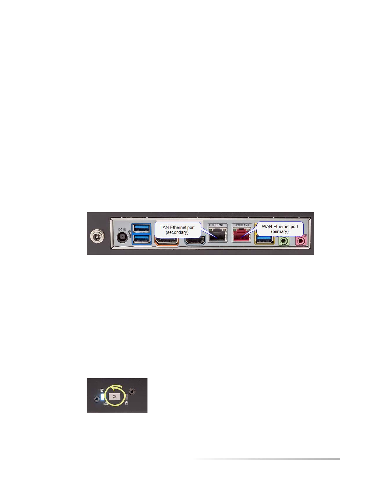
The back of the Helix Broadcaster machine provides the power input and a primary Ethernet
port (WAN port), which is labeled with a default IPv4 address. Plug the power cable into the
power input and connect the WAN port to your network using an Ethernet cable (not
provided).
Ethernet Ports on an Intel Board
CHAPTER
1
Tip: The WAN port will be labeled with a default IP address. With an Intel board, the
port is on the right. On a Supermicro board, it is on the left.
Functional Connectors
Hardware connectors other than the Ethernet ports and the capture card inputs on the Helix
Broadcaster 100 front and back plates are not functional. This includes USB ports, microphone
and speaker jacks, and digital output ports such as HDMI.
Power Switch
Once the power and network cable are connected, press the power switch on the front of the
unit to start the machine.
Power Switch
2
Page 7

Helix Broadcaster 100 Touch Screen User Guide CHAPTER 1: System Setup
Tip: Depress the power switch approximately five seconds to turn the unit off.
Press the power switch briefly or tap the screen if the screen times out.
Setting the WAN Address
The back of the Helix Broadcaster 100 lists the default IP address for the WAN port. If you
must change the WAN IP address or enable DHCP before placing the Helix Broadcaster
machine on your network, follow the procedures below.
Tip: If you can place the machine on your network without changing the
default IP address at first, you can use the machine immediately and log in to
the browser or SSH interface as described on page 5. You can then modify
network settings, such as setting the address for both the primary and
secondary Ethernet ports.
Network Setup Screen
Do the following to display the Network Setup screen where you can enable DHCP or set the
static IP address.
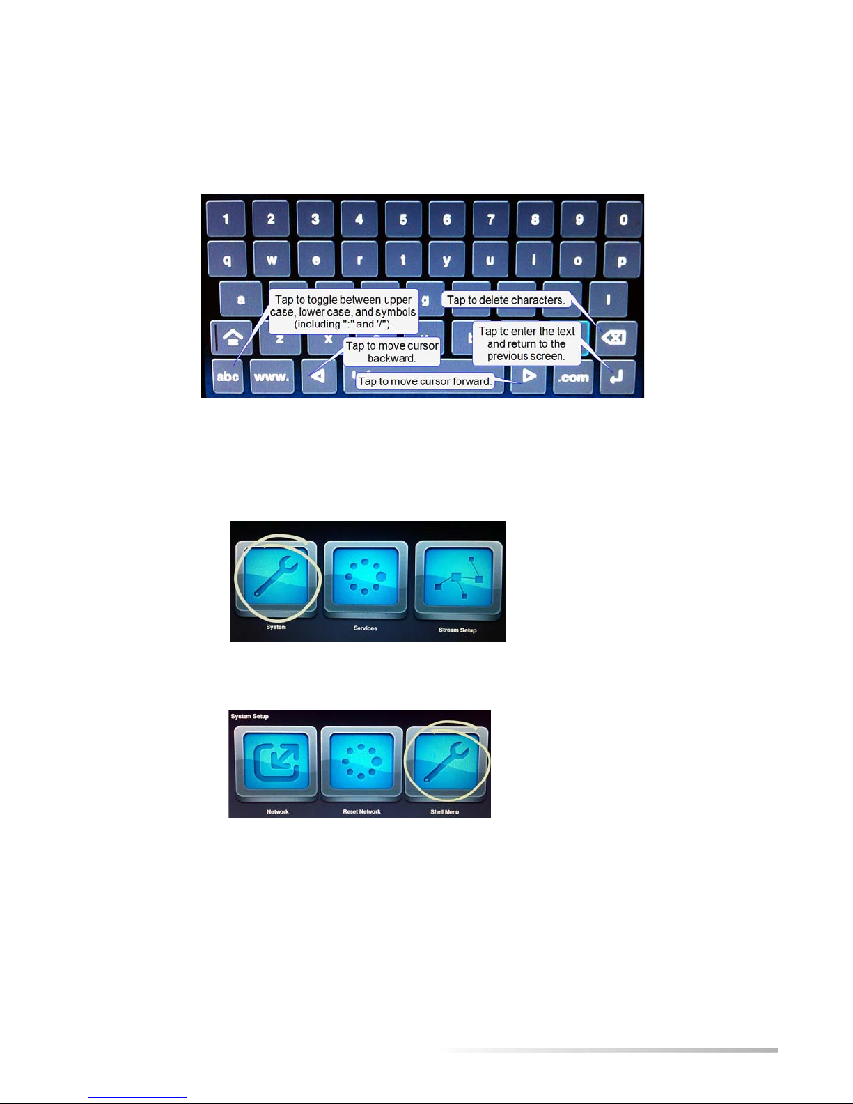
➤ To display the network setup screen:
1. Tap System on the Appliance Manager menu.
System Category on Appliance Manager Screen
2. Tap Network on the System Setup menu that appears.
Network Category on System Setup Screen
3. The Network Setup screen appears. You can then configure DHCP or set a static address as
described next.
DHCP Lookup
If your network uses DHCP to assign IP addresses, set Helix Broadcaster to query the network
and receive an IP address.
3
Page 8

Helix Broadcaster 100 Touch Screen User Guide CHAPTER 1: System Setup
➤ To enable DHCP:
1. On the Network Setup screen, tap the DHCP radio button.
DCHP Setup
2. Tap OK.
3. Reboot the machine:
a. Close the
b. Tap
c. Tap
4. Navigate back to the
5. The
Static IP field will list the IP address assigned to the Helix Broadcaster machine.
Tip: To highlight the network settings, you can tap the Static radio button. Be
sure to tap
System Setup screen.
Services on the Appliance Manager menu.
Reboot Now.
Network Setup page.
DHCP again or cancel the changes to continue using DHCP.
Static IP Address
Follow this procedure to set a specific IP address for the Helix Broadcaster WAN port.
1. On the
Static IP Setup
Network Setup screen (see page 3), tap the Static radio button.
2. In the Static IP field, press and hold the “-” and “+” buttons to set each decimal value for
the IPv4 address you want to assign to Helix Broadcaster.
3. Set the values for
4. Tap
OK.
Mask, Gateway, and DNS as specified by your network administrator.
4
Page 9

Helix Broadcaster 100 Touch Screen User Guide CHAPTER 1: System Setup
5. Reboot the machine:
a. Close the
b. Tap
c. Tap
Services on the Appliance Manager menu.
Reboot Now.
6. Navigate back to the
correct value.
Helix Broadcaster Interfaces
Helix Broadcaster 100 provides three interfaces that allow you to perform various functions:
• touch screen interface
This document describes the Helix Broadcaster 100 touch screen interface, which allows
you to perform basic encoding tasks. Using this interface, you can receive two network
inputs and two capture card inputs. For each input, you can encode up to three outputs.
• browser interface
The browser interface (see page 7) gives you full access to Helix Broadcaster 100, providing
more encoding options than the touch screen. It allows you to configure the embedded
Helix Server as well as perform file-to-file encoding.
Note: Once Helix Broadcaster is available on your network, you can use the
browser interface rather than the touch screen to carry out all system functions.
System Setup screen.
Network Setup page and verify that the IP address has been set to the
• console menu
The console menu gives you access to Helix Broadcaster 100 configuration and network
functions. Once Helix Broadcaster is available on your network, you can use the console
menu through SSH as explained in Appendix A beginning on page 32.
Touch Screen Interface
When Helix Broadcaster starts up, it displays the Appliance Manager menu on its touch screen.
Appliance Manager Menu
System Functions and Services
The Appliance Manager icons give you access to the system functions.
System
Services
Stream Setup
Set basic system features such as the WAN IP address.
Access system services such as rebooting the machine.
Receive inputs as described in Chapter 2 and encode outputs as described in Chapter 3.
5
Page 10
Helix Broadcaster 100 Touch Screen User Guide CHAPTER 1: System Setup
Virtual Keyboard
When you tap a text field on the touch screen, a virtual keyboard appears.
Virtual Keyboard
Shell Menu
The Shell Menu options give you access to operations not related to stream encoding.
1. Tap the
System Category on Appliance Manager Screen
System icon on the Appliance Manager menu.
2. On the System Setup menu that appears, tap the Shell Menu icon.
Shell Menu Access on the System Setup Screen
Note: The Reset Network feature is not currently functional.
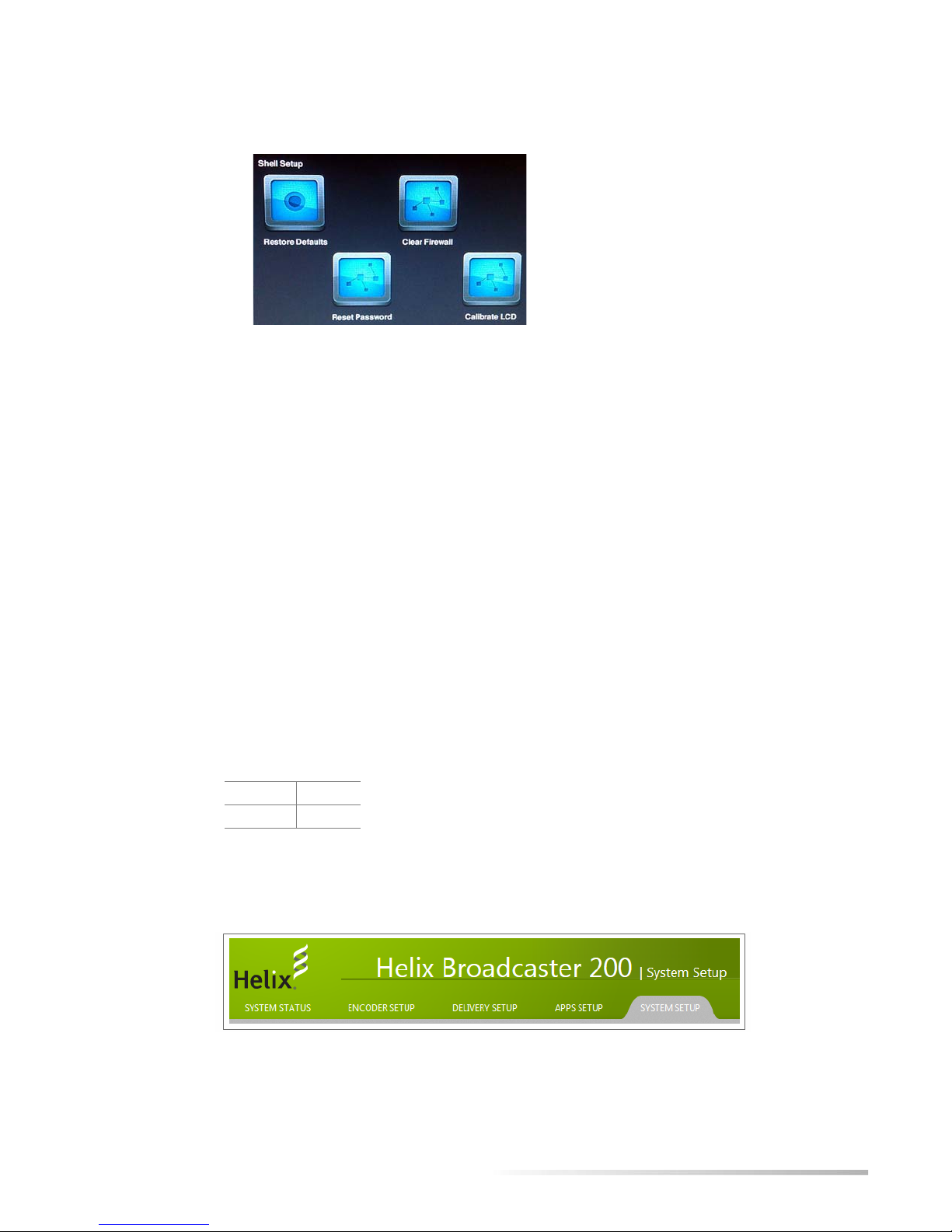
3. The
Shell Setup menu appears.
6
Page 11
Helix Broadcaster 100 Touch Screen User Guide CHAPTER 1: System Setup
Shell Menu Options
4. Choose from these options:
• Restore Defaults — Resets Helix Broadcaster to its factory defaults, erasing stream
confirmation information and returning the unit to its default IP address.
Tip: You can save the configuration to file and later restore it. Using the
browser interface, navigate to
• Clear Firewall — Suspends the firewall settings that have been set up using the browser
interface’s
• Reset Password — Returns the log-in password to the default value of admin.
• Calibrate Touchscreen — Displays an interactive series of prompts that allow you to
Network Setup category under the System Setup tab.
System Setup > Firmware Setup > Config Backup.
recalibrate the touch screen interface.
Browser Interface
Once Helix Broadcaster is connected to your network, you display the browser interface from
any machine on your network. Use the secure HTTP protocol (HTTPS) to access the Helix
Broadcaster IP address. For example:
https://98.111.12.114
You will be prompted to enter the administrator name and password. The defaults are:
user name admin
password admin
Once you log in, you can access Helix Broadcaster functions that are organized in tabs that
appear at the top of the page.
Tabbed Functional Areas
7
Page 12

Helix Broadcaster 100 Touch Screen User Guide CHAPTER 1: System Setup
Click the appropriate tab to manage the various parts of Helix Broadcaster:
System Status
Encoder Setup
Delivery Setup
Apps Setup
System Setup
Tip: Change the administration password by clicking the System Setup tab,
clicking the
and confirm the new password in this page.
For More Information: For more information about using the browser-based
interface, refer to Helix Broadcaster Quick Start Guide.
Display information about CPU usage, network bandwidth, and stream encoding.
Configure inputs and outputs.
Deliver content to media players using Helix Server.
Configure services such as HTTP, FTP, and SNMP.
Set up network addresses, turn services on and off, and update firmware.
Web Server Setup category, and choosing Config Web Server. Enter
8
Page 13

Chapter 2: INPUTS
Capture Input
CHAPTER
2
This chapter describes how to acquire input from a camera or microphone
connected to the Helix Broadcaster hardware. You can also receive input from a
satellite link or another server over your network.
The back of the Helix Broadcaster machine contains an audio/video capture card that has one
or more SDI or HDMI inputs. Depending on the capture card, Helix Broadcaster is capable of
accepting output from most cameras in NTSC, PAL, or HD format. It can also accept input
that uses any of the following types of compression.
video MPEG-1, MPEG-2, MPEG-4, H.264
audio MPEG-1, MPEG-2, MPEG-3, AC3, MPEG-4A (H.264 audio), Ogg-Vorbis
Sample Capture Card Inputs
Capture Input Setup
To set up an input from the capture card, tap Stream Setup on the Appliance Manager screen
and choose one of the
Capture Card Input Choices
SDI or HDMI entries.
9
Page 14

Helix Broadcaster 100 Touch Screen User Guide CHAPTER 2: Inputs
On the Stream Setup screen that appears, tap Input Setup to define the input characteristics.
Input Setup Selection
The Input Setup screen defines the characteristics of the input stream.
Capture Input Setup Screen
Startup Mode
Video Mode
For Startup Mode, the default is Manual, which means that you start the encoding process as
described in the section “Stream Control” on page 31. The
functional, although you can set
Always On in the browser interface (see page 7). In this case, the
Automatic value is currently not
encoding process begins when you define the output and start the stream manually. After that,
it restarts automatically if Helix Broadcaster is rebooted.
Under Video Mode, select the specifications of the incoming video, including the frame size
(such as
1920x1080) and the frame rate (such as 59.94). The drop-down lists the common
output formats for NTSC, PAL, and HD video. Drag the slider to view all of the options. Tap an
input format description to highlight the radio button for that input format.
10
Page 15

Helix Broadcaster 100 Touch Screen User Guide CHAPTER 2: Inputs
Video Mode
Warning! No video will be encoded if the input setting does not match the video
device’s output format exactly.
Audio Configuration
Audio Channels
Input Buffer Size
Network Input
For Audio Config, select one of the following:
• Embedded — digital audio embedded in a video track by a camera
• AES/EBU — digital audio output from a microphone
• Analog — analog audio format from a microphone
For Audio Channels, select the number of audio channels that the input device records. The
typical value is
2, indicating stereo sound, although inputs may support multiple channels.
The input buffer size sets the number of milliseconds of input data that is buffered before it is
encoded. The default value is
17), set a value of
200 or 100.
300 milliseconds. For low-latency encoding and delivery (see page
The following sections explain how to receive input over your local network or from the
Internet. Typical sources are streaming servers, an MPEG-TS encoder, or a satellite link.
Network Input Setup
On the Appliance Manager screen, tap Stream Setup and choose one of the Net entries.
11
Page 16

Helix Broadcaster 100 Touch Screen User Guide CHAPTER 2: Inputs
Network Input Choices
On the Stream Setup screen that appears, tap Input Setup to define the input characteristics.
Input Setup Selection
The following is a sample setup screen that appears. The options on the screen vary depending
on the
Network Input Setup Screen
Startup Mode
For Startup Mode, the default is Manual, which means that you start the encoding process as
described in the section “Stream Control” on page 31. The
functional, although you can set
encoding process begins when you define the output and start the stream manually. After that,
it restarts automatically if Helix Broadcaster is rebooted.
Input Protocol
The Input Protocol drop-down defines the type of input stream or file that is acquired. The
UDP and RTP methods are push methods in which the remote server delivers the stream to the
designated Helix Broadcaster IP address and port. The HTTP, RTSP, and RTMP methods are
Input Protocol choice.
Automatic value is currently not
Always On in the browser interface (see page 7). In this case, the
12
Page 17

Helix Broadcaster 100 Touch Screen User Guide CHAPTER 2: Inputs
pull methods in which Helix Broadcaster requests the stream from the remote server using the
designated URI.
Input Protocols
Protocol Purpose
udp User Datagram Protocol. This option is for a UDP stream that does not use a control
protocol such as RTSP. Use it for input from an MPEG-2 TS encoder or a satellite link.
rtp Similar to the UDP method. Use this instead if data is delivered using the Real-Time
Transport Protocol packet format.
http HyperText Transport Protocol. This option is for receiving media from a web server or any
other server that does not support RTSP or RTMP. You can use this option to load an
SDP file used to acquire a stream, for example.
rtsp/udp Real-Time Streaming Protocol with User Datagram Protocol. This option is
recommended for receiving live input from an RTSP-capable server such as Helix Server.
It can also be used for RTSP cameras. By using UDP, the source can deliver media packets
more efficiently than with TCP. However, lost packets are not resent and may cause lapses
in the media stream.
rtsp/tcp Real-Time Streaming Protocol with Transmission Control Protocol. Using the TCP
transport with RTSP results in greater network overhead, but lost packets can often be
redelivered by the network layer. This option provides better error resilience for RTSP
sources transmitting over the Internet. It is not recommended for use with live streams
delivered by a Helix Server, however.
rtsp/http Real-Time Streaming Protocol over HTTP. This is used primarily to work around firewalls
that restrict RTSP communications as long as the RTSP source supports HTTP. Because
RTSP/HTTP is less efficient for transporting media than RTSP/UDP or RTSP/TCP, it is
not recommended if either of those options is available.
rtmp Variations of the Real-Time Messaging Protocol used by Flash Media Servers:
rtmp – standard protocol (recommended)
rtmpt – RTMP cloaked as HTTP to work around firewalls
rtmpe – encrypted RTMP
rtmps – secure RTMP
rtmpte – encrypted and cloaked RTMP
rtmpts – secure and cloaked RTMP
UDP and RTP Input
If you choose udp or rtp for Input Protocol, you specify the unicast or multicast address and port
where Helix Broadcaster receives the stream.
RTP or UDP Stream Setup
13
Page 18

Helix Broadcaster 100 Touch Screen User Guide CHAPTER 2: Inputs
Input Interface
In the Input Interface drop-down, choose which Helix Broadcaster Ethernet connection receives
the stream. Typically this is the
WAN port, which is the main IP address. If you have configured
the secondary Ethernet port using the browser interface (see page 7), you can choose the
address or
All to monitor both the WAN address and the LAN address.
Note: Typically you do not use the Local Adapter setting for network input. This
is the loopback address (
127.0.0.1), which can be used only for a stream that
originates on the Helix Broadcaster machine.
Input Type (Unicast or Multicast)
For a UDP or RTP input, select Unicast or Multicast as the Input Type depending on the IP
address where the stream is directed. If you choose
Multicast, the Multicast IP field appears. Tap
this field and use the virtual keyboard (see page 6) to enter the multicast address in the range
from
224.0.0.0 to 239.255.255.255.
Note: Receiving a multicast stream requires that Helix Broadcaster resides on a
multicast-enabled network.
Buffer Size
LAN
The input buffer size sets the number of milliseconds of input data that is buffered before it is
encoded. The default value is
value of
200 or 100.
For More Information: For details about low-latency encoding, refer to “Low-
Latency Encoding Values” on page 18.
Input Port
For a UDP or RTP stream, tap the Input Port field and use the virtual keyboard to set the Helix
Broadcaster port that receives the remote server stream. If the stream is multicasted, select the
port on the multicast address where the stream is sent. The remote server that initiates the
stream must be configured to send the stream to this port.
HTTP, RTSP, and RTMP Input
If you choose http, rtsp, or rtmp for Input Protocol, you specify the network address where Helix
Broadcaster acquires the stream.
HTTP Input Setup Screen
300 milliseconds. For low-latency encoding and delivery, set a
14
Page 19

Helix Broadcaster 100 Touch Screen User Guide CHAPTER 2: Inputs
Remote URL
Tap t he Remote URL field and use the virtual keyboard (see page 6) to set the URL where Helix
Broadcaster acquires the steam. The URI format is the following, in which a user name and
password can be included in the URL if required by the remote server:
protocol://username:password@address/path/s tream_or_f ile_name
Examples:
http://192.168.123.1:80/stream.sdp
rtsp://helixbcd:TR9ls3UIP@192.168.123.1:554/test.sdp
rtmp://192.168.123.1:1935/live/myvideo
Input Buffer Size
The input buffer size sets the number of milliseconds of input data that is buffered before it is
encoded. The default value is
Helix Server, set a buffering value of
300 milliseconds. For receiving an RTSP stream from another
600 ms.
15
Page 20

Chapter 3: OUTPUTS
Output Selection
CHAPTER
3
For each input you define, you can create up to three outputs using the touch
screen. You might create different outputs to generate streams with different
streaming bandwidths or output ratios, for example.
To define an output, tap Stream Setup on the Appliance Manager screen. On the Stream Setup
menu, choose the stream input, such as
want to define (
Output Stream Selection
#1, #2, or #3).
Net#1 or SDI#1. Then tap the icon for the output you
The following table lists the types of outputs that can you create.
Output Protocols
Protocol Purpose
UDP with TS envelope
RTP with TS envelope
HTTP with TS envelope
HLS - HTTP Live Streaming
Smooth Streaming push
RTMP push with FLV
envelope
Data delivered with user datagram protocol and a transport stream
wrapper. This can be used to send the stream to a satellite link or to other
encoders or servers. See page 17.
Similar to the UDP method, this output type delivers data using a
standards-based RTP packet format. See page 17.
This is a pull method that allows a client such as a server to request the
stream using an HTTP URL. This method can be used to work around
restrictive firewalls. See page 18.
HLS output delivers transport stream files over HTTP. It is used with iOS
devices such as the iPad as well as compatible devices. See page 19.
Not currently supported.
This method uses Flash packaging along with the RTMP protocol. You
can use this method to deliver the stream to a Flash Media Server. See
page 21.
(Table Page 1 of 2)
16
Page 21

Helix Broadcaster 100 Touch Screen User Guide CHAPTER 3: Outputs
Output Protocols (continued)
Protocol Purpose
UDP with Low Latency TS
Helix Media Server
Note: For any output type, set Enabled to Yes in the top field to enable Helix
Similar to the other UDP method, this output type is designed to
minimize the latency between the time the live stream is encoded and
when it is pushed to the network. See page 17 for instructions. You will
also need to set buffering values as described on page 18.
This method passes the stream to the embedded Helix Server for delivery
to media clients. You can also use this method if you want Helix Server to
forward the stream to other types of servers or content distribution
networks. See page 21.
(Table Page 2 of 2)
Broadcaster to encode the output.
UDP and RTP Outputs
The following push output types use a transport stream wrapper similar to the output from an
MPEG-2 encoder used in television production. These options can be used to deliver the
encoded output to a satellite uplink, for example.
• UDP with TS envelope
This output delivers the encoded output using a transport stream and User Datagram
Protocol as the network transport layer protocol.
UDP Output Screen
• UDP with Low Latency TS
This output format is similar to the preceding except that it enables the encoder to buffer
less of the transport stream before delivering the output. This results in lower end-to-end
latency, enabling the target to receive the event stream faster than with standard latency.
Note: Low-latency encoding is designed for use with capture input rather than
network input.
• RTP with TS envelope
This output delivers the encoded output as a transport stream using Real-Time Transport
Protocol for data packaging. Choose this only if you know that the target supports the
standards-based RTP packet format.
17
Page 22

Helix Broadcaster 100 Touch Screen User Guide CHAPTER 3: Outputs
IP Address
In the IP Address field, use the virtual keyboard (see page 6) to enter the IP address where Helix
Broadcaster sends the stream. On a multicast-enabled network, you can use a multicast address
in the range from
224.0.0.0 and 239.255.255.255.
Output Port
Tap t he Output Port field and use the virtual keyboard to set the port on the destination IP
address where the output stream is delivered. For multicasting, use an available port on the
multicast address as defined by the network administrator.
Note: If you are creating multiple outputs, the different streams must use a
different port on the destination IP address. For example, one output stream
may use port 9000 while another stream may use port 9010.
Interface
In the Interface drop-down, select which IP address Helix Broadcaster uses to send the data to
the target. Typically this is the
the secondary Ethernet port using the browser interface (see page 7), you can choose the
address or
All.
WAN port, which is the main IP address. If you have configured
LAN
Low-Latency Encoding Values
If you are using the UDP with Low Latency TS output, use the following buffering values to
achieve lower latency in data throughput:
• For the input, set Buffer Size to 200 (see page 11).
• On the Filters tab, set the output Buffer Size to 200 (see page 29). You can lower this value to
100 if necessary to achieve more latency reduction.
• On the Video tab, set Video Method to Constant Bitrate (see page 26).
HTTP Output
The HTTP with TS envelope output type allows a transport stream wrapper to be pulled from
Helix Broadcaster using an HTTP URL. You can use this method to work around restrictive
firewalls if necessary or if a pull-stream is required.
Note: Typically you do not use the Local Adapter setting, which is the loopback
address (
127.0.0.1), for output.
18
Page 23

Helix Broadcaster 100 Touch Screen User Guide CHAPTER 3: Outputs
HTTP Output Screen
HTTP Path
For HTTP Path field, use the virtual keyboard (see page 6) to set a virtual path that uniquely
identifies this stream. The path designation appears in the URL following the address and
port. Helix Broadcaster adds an
.sdp file extension to the path name automatically.
Bind Port
In the Bind Port field, Helix Broadcaster automatically selects a port where the HTTP stream
will be available. You can use the virtual keyboard (see page 6) to set a different port value. In
general, you can use any open port, and ports in the range
not use any of the following reserved ports:
80, 81, 88, 443, 444, 554, 1935, 4443, 25599
2000 to 64000 are recommended. Do
Interface
Request URL
HLS Output
Note: If you are creating multiple outputs, each output stream must use a
different port unless you set a unique HTTP path for each stream.
In the Interface drop-down, select the IP address where Helix Broadcaster makes the HTTP
stream available. Typically this is the
WAN port, which is the main IP address. If you have
configured the secondary Ethernet port using the browser interface (see page 7), you can
choose the
LAN address or select All.
Note: Typically you do not use the Local Adapter setting, which is the loopback
address (
127.0.0.1).
The HTTP request URL combines the IP address of the interface, the bind port, and the HTTP
path along with the
http://10.124.4.113:7880/streampath.sdp
.sdp file name. For example:
With the HLS - HTTP Live Streaming output method, Helix Broadcaster encodes a series of
transport segments (file extension
.ts) that are indexed by a playlist (file extension .m3u8). After
the HLS client requests and receives a generated playlist, it requests the individual transport
segments. All file delivery takes place using HTTP.
19
Page 24

Helix Broadcaster 100 Touch Screen User Guide CHAPTER 3: Outputs
HLS Output Screen
Using the touch screen, you can generate a single-rate HLS stream or a multi-rate stream with
up to three streaming rates. In a multi-rate stream, a master playlist links the client to separate
playlists for the single-rate streams. The client can then request the
.ts content from the
different single-rate playlists as needed.
Note: For media delivery to iOS devices such as the iPhone and iPad, HLS
output must be encoded with H.264/AAC codecs.
Stream Name
For Stream Name, set a name for the output stream. Helix Broadcaster generates the single-rate
playlist using this stream name. In a multi-rate stream, each stream name typically includes a
designation for the streaming rate. For example, the stream name
500K.m3u8.
500K results in the playlist
Master Name (Multi-rate Streams)
To generate a multi-rate stream, create up to three outputs with similar H.264/AAC encoding
profiles. Each output should use a different video streaming rate, such as 500 Kbps, 750 Kbps,
and 1000 Kbps. The streams can use the same or different audio rates. In the
for each output, set the same name, such as
master playlist, as in
master.m3u8.
Request URLs
The setup screen lists the request URLs, which are based on the stream names.
Single-rate Stream
If you are encoding a single-rate stream, link the HLS client to the single-rate playlist URL
listed on the screen. For example:
http://10.124.4.113:80/hls/m3u8/500k.m3u8
Multi-rate Streams
For a multi-rate stream, the client can request the master playlist. The HLS client then requests
individual streams based on information contained in the master playlist. For example:
http://10.124.4.113:80/hls/master.m3u8
Master Name field
master. This name automatically becomes the
20
Page 25

Helix Broadcaster 100 Touch Screen User Guide CHAPTER 3: Outputs
RTMP Output
The output type RTMP push with FLV envelope uses the RTMP protocol to transmit the output as
a Flash stream. You can use this output type to deliver the output to a Flash Media Server.
RTMP Output Screen
Tip: Using the browser interface (see page 7), you can deliver the RTMP stream
to the Akamai content distribution network.
Target URI
In the Target URI field, use the virtual keyboard (see page 6) to specify the address of the target
server. The URI specifies the RTMP protocol and the server’s IP address. Typically it also
includes the
rtmp://183.43.12.21:1935/live
live application name. For example:
RTMP Name
For RTMP Name, set the name of the stream delivered to the server. This name is appended to
target URI value. For example:
flashlive
Helix Media Server
The Helix Media Server output type delivers the encoded stream to the embedded Helix Server.
You can use this method to make the stream available to popular media clients. You may also
want to use it to forward the stream to content distribution networks or to implement features
such as live stream archiving.
Tip: The port value is not required as long as the destination server uses the
default RTMP port of
Note: Flash stream variables (such as %b to indicate the stream bit rate) are not
1935 to receive the Flash stream.
supported in the stream name.
21
Page 26

Helix Broadcaster 100 Touch Screen User Guide CHAPTER 3: Outputs
Helix Media Server Output
Note: The stream must be encoded as H.264/AAC. Helix Server rejects any
stream encoded with different codecs.
Helix Stream Name
For Stream Name, use the virtual keyboard (see page 6) to enter a stream name without spaces.
You can create a name using letters, numbers, or any of the following special characters:
- \ / ! @ # $ % ^ & * ( ) _ \ - + = | } { ; : < > , . ? ~
Helix Server Service
You must start the Helix Server process using the browser interface described on page 7. Under
the
Delivery Setup tab, the Service Control page allows you to stop and restart the Helix Server
process independently of any encoding jobs being performed by Helix Broadcaster.
Helix Server Service Control
1. Ensure that the Enable Helix Server box is checked to enable all Helix Server functions.
2. On your first set-up, the Helix Server end-user license agreement (EULA) appears. Click to
accept the agreement. Once you have done so, the EULA no longer appears onscreen.
3. Click
4. On the
Update.
Service Control palette on the right side of the Service Control page, click the Start
button to turn the Helix Server service on.
22
Page 27

Helix Broadcaster 100 Touch Screen User Guide CHAPTER 3: Outputs
Service Control Palette
Helix Media Server Playback Links
The following are sample client playback links for the Helix Media Server output method. These
links assume a Helix Broadcaster IP address of
Substitute values appropriate for your stream setup. Helix Server is available on both the WAN
address and the LAN address (if configured).
HLS Client Link http://98.111.12.114:88/Segments/HLS_TS/mptslive/camera.m3u8
DASH Client Link http://98.111.12.114:88/Segments/DASH_MP4/mptslive/camera.mp4.mpd
Flash Client Link rtmp://98.111.12.114/rtmplive/mptslive/camera
RTSP Client Link rtsp://98.111.12.114/rtsplive/mptslive/camera
Note: Helix Server use port 88 for HTTP and port 444 for HTTPS. These are not
the standard ports used for HTTP protocols. The port values
in request URLs.
98.111.12.114 and a stream name of camera.
must be included
For More Information: Refer to the online help available on the Helix Server setup
pages under the
Delivery Setup tab.
23
Page 28

Chapter 4: VIDEO AND AUDIO OPTIONS
When you create an output as described in Chapter 3, you can define video and
audio encoding options. The section “Stream Control” on page 31 explains how to
encode a stream once you have defined the input and set up all of the outputs.
Video Options
The Video tab for an output sets the video format and streaming rate for the stream.
Video Encoding Settings
CHAPTER
4
Video Codec
The Video Codec drop-down selects the video format created by the Helix Broadcaster encoder:
• No Video Transcoding
If you select this option, Helix Broadcaster will not re-encode the stream, which saves
processing power. The stream is passed through as-is, however, and you cannot change
characteristics such as streaming speed or aspect ratio.
• MPEG2 Video
MPEG-2 video is common to television production. It should be used only at output rates
of 1 Megabit per second or higher. This format is typically not renderable by Internet
media clients.
• Remove Video
If this option is selected, Helix Broadcaster does not encode or pass through any video.
This results in an audio-only stream. When you choose this option, other video settings are
ignored.
24
Page 29

Helix Broadcaster 100 Touch Screen User Guide CHAPTER 4: Video and Audio Options
• H264 Video
Use this to encode the video with the H.264 codec. If the input video stream is already
encoded as H.264, choose this option if you need to change the stream characteristics,
such as setting a different streaming speed.
Tip: Choose H.264 video to deliver video to Helix Server and to make it available
the widest range of clients. HLS clients, for example, require H.264.
Video Bit Rate
For Video Bit Rate, select a streaming bit rate for the video. The encoded stream’s total rate is
the sum of the video bit rate and the audio bit rate (see page 30). The bit rate you select should
be influenced by the streaming network, the client device, and video frame size, video frame
rate, and the desired media quality.
Video Bit Rate
Video Format
The Video Format drop-down sets the frame size of the encoded video. If the frame size is in the
same aspect ratio (such as 4:3 or 16:9) as the input video, the video is scaled smaller or larger as
necessary to meet the target size. If the aspect ratio is different, the scaling mode (see page 27)
determines how the video is resized.
Video Format
25
Page 30

Helix Broadcaster 100 Touch Screen User Guide CHAPTER 4: Video and Audio Options
Video Method
For Video Method, select one of the following:
• Average Bit Rate
Average bit rate encoding keeps the video streaming rate at the selected bit rate as an
overall average. The actual streaming rate may be above or below the selected bit rate at any
given time, however. This f luctuation helps to improve quality over constant bit rate
encoding. Average bit rate encoding can be used with high-speed networks such as
corporate LANs, cable modems, and mobile LTE.
• Variable Bit Rate
Variable bit rate encoding gives more bandwidth to scenes that are hard to compress,
making the most visible difference in videos that have fast-moving, high-action scenes. To
accommodate variable bit rates, the client network must be able to handle large bandwidth
spikes. This is typically acceptable on corporate networks and for cable modem use. It is
not advisable for DSL or mobile broadband connections.
• Constant Bit Rate
Use constant bit rate for low-latency encoding. It keeps the video data more tightly set to
the bandwidth target than does average bit rate encoding. The quality may be lower than
with average bit rate encoding, but the streaming rate is stable. You may also want to
choose this encoding method when streaming over networks that have tightly constrained
bandwidths, such as 3G mobile networks.
Video GOP Size
Filter Options
The Video GOP Size field sets the “group of pictures” size in the video output. Larger values
result in higher compress. Lower values result in better visual quality. Unless you have a specific
need to change this value, leave it set to the default.
On the Filters tab you can set options that affect how Helix Broadcaster modifies video output.
Filters Tab
26
Page 31

Helix Broadcaster 100 Touch Screen User Guide CHAPTER 4: Video and Audio Options
Scaling Mode
The Scaling Mode settings are currently not functional. If the input and output aspect ratios
differ, Helix Broadcaster increases or decreases the video size as necessary to fit the output
settings. This can cause visible distortion. The following figure illustrates a 16:9 video changed
to a 4:3 aspect ratio, which compresses the video image in its horizontal dimension.
Framerate
The video frame rate determines how many visual frames are encoded for display each second.
The
Framerate drop-down provides several choices for altering the frame rate in the output.
Video streamed over the Internet is typically encoded at a frame rate of 15 to 30 frames per
second, although lower-bandwidth videos may be encoded at slower frame rates. The default
value, which preserves the input frame rate, is
Keep Source Framerate.
Framerate
Downsampling or Upsampling
The downsampling and upsampling values allow you to change the input and output frame
rates among those used in film and video production:
feature film 24 frames per second
PAL video
NTSC video 30 frames per second
25 frames per second
27
Page 32

Helix Broadcaster 100 Touch Screen User Guide CHAPTER 4: Video and Audio Options
Dropping Frames
Helix Broadcaster provides several options to drop frames and achieve a lower frame rate.
Dropping frames may make the video appear jerky, however.
Deinterlacing
Deinterlacing removes jaggedness from certain video sources. Typically you can leave this field
set to its default value of
input stream as needed. If you have specific requirements, you can use the drop-down to turn
off deinterlacing or choose a specific method of deinterlacing.
Deinterlacing
Auto. In this case Helix Broadcaster automatically deinterlaces the
Tip: Deinterlacing doubles the video frame rate. For example, it turns 30
frames-per-second NTSC video into a 60 fps output. To drop added frames,
select
Drop 1 out of every 2 frames in the Framerate drop-down (see page 27).
What is Deinterlacing?
An NTSC video camera running at 30 frames per second captures the odd-numbered lines of a
field in 1/60th of a second and the even-numbered lines in the next 1/60th of a second. It then
interlaces the two to create the frame. Because half of the field's lines are captured a fraction of
a second later than the other half, fast-moving objects may appear jagged. This is the result of
the object advancing slightly within 1/60th of a second. Deinterlacing removes this jaggedness.
Detail of Interlaced Video (left) and Deinterlaced Video (right)
28
Page 33

Helix Broadcaster 100 Touch Screen User Guide CHAPTER 4: Video and Audio Options
Buffer Size
The output buffer size sets the number of milliseconds of output data that is buffered before it
is delivered to the output destination. The default value is
encoding and delivery, set a value of
For More Information: For details about low-latency encoding, refer to “Low-
200 or 100.
300 milliseconds. For low-latency
Latency Encoding Values” on page 18.
Audio Options
The Audio tab for an output sets the audio format and streaming rate.
Audio Settings
Audio Codec
The Audio Codec drop-down determines how the input audio is encoded in the output:
• No Audio Transcoding
If you select this option, Helix Broadcaster will not re-encode the stream, which saves
processing power. The audio is passed through as-is, however, and you cannot change
characteristics such as streaming speed or sampling rate.
• MPEG2 Audio
MPEG-2 audio is common to television production. It should be used only at output rates
(video plus audio) of 1 Megabit per second or higher. This format is typically not
renderable by Internet media clients.
• Remove Audio
If this option is selected, Helix Broadcaster does not encode or pass through any audio.
This results in a video-only stream. When you choose this option, other audio settings are
ignored.
Note: Do not select this option when encoding from an SDI or HDMI input.
• AAC Audio
Encode the audio with an AAC codec. If the input stream is already encoded as AAC,
choose this option if you need to change stream characteristics, such as setting a different
streaming speed or AAC profile.
29
Page 34

Helix Broadcaster 100 Touch Screen User Guide CHAPTER 4: Video and Audio Options
Audio Bitrate
For Audio Bitrate, set the audio’s streaming bit rate in Kilobits per second (Kbps):
• 64
• 128
• 256
• 384
Note: The encoded stream’s total streaming speed is the sum of the audio bit
rate and the video bit rate (see page 25).
Audio Rate
In the output’s Audio Rate drop-down, select the sampling rate for the encoded audio in Hz:
• 32,000
• 44,100
• 48,000
Tip: If you are streaming to Flash Player, choose 44,100 Hz, which is that
player’s preferred sampling rate. Other rates may introduce audio distortion.
Most other media players will play a 44.1 kHz stream without complications.
Audio Channels
The Audio Channels drop-down selects the number of audio channels that are recorded. Use
the default value of
input and the output settings. Select
to stereo. Select
Audio Profile
For AAC audio, choose from the following:
Note: If the input audio's sampling rate does not match the sampling rate you
choose here, Helix Broadcaster resamples the input when it creates the output.
Auto to have Helix Broadcaster select which channels to record based on the
2 if you have multi-channel input that you want to turn
1 to encode mono audio.
Note: Helix Broadcaster cannot increase the number of channels present in the
input. For example, selecting
5 does not increase the number of discrete
channels if the input is stereo.
• Auto
Helix Broadcaster chooses the audio profile based on the other input and output settings.
• LC
Advanced Audio Coding Low Complexity (AAC-LC) creates audio content at bit rates
starting at 8 Kbps. Most media devices support AAC-LC audio, making it the safest choice
for reaching the widest audience.
30
Page 35

Helix Broadcaster 100 Touch Screen User Guide CHAPTER 4: Video and Audio Options
• HE-AAC
High-efficiency AAC, which is also known as AAC Plus (AAC+), provides Spectral Band
Replication (SBR) and more efficient encoding than AAC-LC. It requires more processing
power for the media player to decode, however, and may not be supported by all client
devices. Choose this option only if you know that your target audience supports AAC Plus.
• HE-AAC v2
Version 2 of High Efficiency AAC, which is also known as Enhanced AAC Plus (EACC+),
adds Parametric Stereo for better sound quality. It requires more processing power for the
media player to decode, however. Choose it only if you know that your target media players
support it.
Stream Control
On a Stream Setup page, tap the Start, Stop, and Restart icons to control the encoding process
for the stream. When you start the stream, all defined outputs for the input will be encoded.
Stream Control
Note: The actions you select affect the stream category (such as Net #1) you
have selected in the menu. Be sure to select the correct stream category before
starting and stopping a process.
Tip: You can restart all running streams at once by tapping Services on the
Appliance Manager main screen and then tapping Restart All Streams.
31
Page 36

Appendix A: CONSOLE SETUP
You can display the Helix Broadcaster 100 console menu using secure shell (SSH).
With the console, you can perform network setup functions such as setting the
addresses for the WAN and LAN port.
Using Secure Shell
If Helix Broadcaster is accessible on your network, you can use secure shell (SSH) to log in to
the console. The following sections explain methods of using SSH from Windows or Linux.
Windows PuTTY Client
On Windows, you can use the PuTTY client, which you can download from your preferred
shareware site or directly from
configure access using SSH on port 22. Unless the IP address has been changed already, log in
with the default IP address listed on the back of the Helix Broadcaster hardware.
APPENDIX
A
http://www.putty.org/. After you install and launch the client,
Linux SSH
PuTTY Windows Client Setup
Log in with the admin account, which you can specify along with the IP address:
admin@HelixBroadcasterAddress
For example:
admin@10.125.15.200
Once you reach the machine with SSH, Helix Broadcaster prompts for the password. Unless it
has been changed already, the default password is:
admin
On Linux, you can use SSH from any command-line shell:
1. Open a command shell.
2. Unless the IP address has been changed, log in with the default IP address listed on the
back of the Helix Broadcaster hardware:
ssh admin@HelixBroadcasterAddress
32
Page 37

Helix Broadcaster 100 Touch Screen User Guide APPENDIX A: Console Setup
For example:
ssh admin@10.125.15.200
3. Helix Broadcaster prompts for the password. Unless it has been changed already, the
default password is:
admin
Console Menu
Once you access Helix Broadcaster directly or by SSH, the main console menu appears.
Console Main Menu
Note the following about using the console:
Network Settings
The following entries on the main menu allow you to view and change network settings:
1) Edit Network Settings
4) Show IP Addresses
• Select main menu or submenu options by entering the letter, number, or combination that
represents the option, such as pressing
• Navigate through setup screens using the arrow keys on your keyboard.
• Delete existing information in setup screens using the Backspace key.
• A carat (^) refers to the Ctrl key. For example, ^X means to press Ctrl and the letter x.
• Press ^X to exit a setup screen. If you made changes, the editor prompts you to press Y to
save the changes or
For More Information: The console uses the Nano text editor. For a command
reference, browse to
Note: After you change the network configuration, you may need to enter r at
N to discard them.
http://www.nano-editor.org/dist/v1.2/nano.html.
1 for Edit Network Settings.
the main menu to reboot the machine and put the changes into effect.
33
Page 38

Helix Broadcaster 100 Touch Screen User Guide APPENDIX A: Console Setup
Showing IP Addresses
Enter 4 at the main menu to display the current IP address settings. The WAN address (see
page 4) is listed as
WAN address is shown below in
...
3: eth0: <BROADCAST,MULTICAST,UP,LOWER_UP> mtu 1500 qdisc pfifo_fast state UP qlen 1000
link/ether 08:60:6e:44:0c:0a brd ff:ff:ff:ff:ff:ff
inet 10.125.15.250/24 brd 10.125.15.255 scope global eth0
inet6 fe80::a60:6eff:fe44:c0a/64 scope link
valid_lft forever preferred_lft forever
...
eth0. Additional IP addresses are eth1, eth2, and so on. For example, the IPv4
bold:
Changing IP Addresses
Enter 1 at the main menu to change an IP address. To set the WAN address (see page 3), enter
e0 (the second character is a zero) at the submenu:
e0) Edit WAN Settings (ctrl-x to exit)
e1) Edit LAN #1 Settings
g) Edit Default Gateway and DNS Settings
IP Address Setup Screen
In the setup screen, use the arrow keys to navigate to the end of the IP address. Press Backspace
to erase the characters. Enter the new address, press
Press
x to return to the main menu.
Editing Network Settings
Enter 1 at the main menu to change network settings such as DHCP (see page 3). Enter g at the
submenu:
e0) Edit WAN Settings (ctrl-x to exit)
e1) Edit LAN #1 Settings
g) Edit Default Gateway and DNS Settings
Ctrl+x to exit, and Y to confirm the changes.
34
Page 39

Helix Broadcaster 100 Touch Screen User Guide APPENDIX A: Console Setup
Networking Setup Screen
In the setup screen, use the arrow keys to navigate to the end of a field and press Backspace to
erase the existing characters. Press
Ctrl+x to exit. Press x to return to the main menu.
35
 Loading...