

Page 1
'\®HELl
blue
BTWO
2-Kanal
2-Channel
Verstarker
Amplifier
Page 2
::::c:
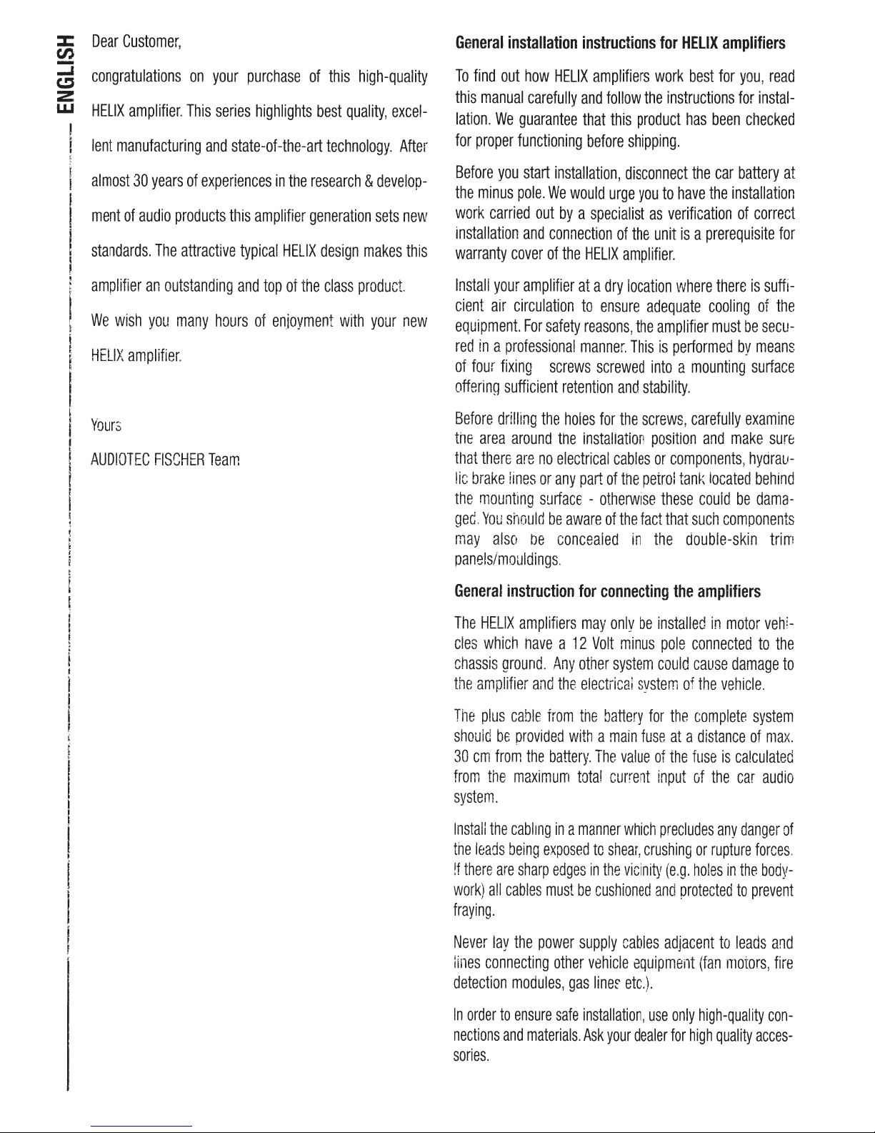
Dear
(/)
::::i
congratulations
C!J
z
w
HELIX
lent
I
'
manufacturing
almost
ment
standards.
Customer,
amplifier.
30
of
audio
years
products
The
attractive
This
of
on
your
purchase
series
and
state-of-the-art
experiences
this
typical
of
highlights
in
the
research & develop-
amplifier
generation
HELIX
this
high-quality
best
quality,
technology.
sets
design
makes
excel-
After
new
this
General
To
this
lation.
for
Before
the
work
installation
warranty
installation
find
out
manual
We
proper
you
minus
carried
cover
guarantee
functioning
pole.
how
HELIX
carefully
start
installation,
We
would
out
by a specialist
and
connection
of
the
instructions
amplifiers
and
follow
that
this
before
urge
of
HELIX
for
work
the
product
shipping.
disconnect
you
to
as
the
unit
amplifier.
HELIX
amplifiers
best
for
you,
instructions
has
the
have
verification
is a prerequisite
for
been
checked
car
battery
the
installation
of
read
instal-
at
correct
for
amplifier
We
HELIX
Yours
AUDIOTEC
an
wish
amplifier
you
FISCHER
outstanding
many
hours
.
Team
and
of
top
of
the
class
en.ioyment
with
product.
your
new
Install
your
amplifier
cient
air
circulation
equipment.
red
in a professional
of
four
offering
Before
the
area
t11at
lic
brake
the
mounting
ged.
may
panels/mouldings
General
The
cles
chassis
the
amplifier
For
fixing
sufficient
drilling
around
there
are
lines
You
should
also
instruction
HELIX
amplifiers
which
nave
ground.
safety
screws
retention
the
the
no
electrical
or
any
surface -otherwise
be
be
concealed
.
a
Any
and
the
at a dry
to
ensure
reasons,
manner.
screwed
holes
for
installation
part
of
aware
of
for
connecting
may
only
12
Volt
other
electrical
location
adequate
the
amplifier
This
is
into a mounting
and
stability.
the
screws,
position
cables
or
components,
the
petrol
these
the
fact
that
in
the
be
installed
minus
pole
system
could
system
where
there
cooling
must
performed
carefully
and
make
tank
located
could
such
components
double-skin
the
amplifiers
in
motor
connected
cause
damage
of
the
vehicle.
is
suffi-
of
the
be
secu-
by
means
surface
examine
sure
hydrau-
behind
be
dama-
trim
vehi-
to
the
to
The
plus
should
be
30
em
from
from
the
system.
Install
the
the
leads
!f
there
are
work)
all
cables
fraying.
Never
lay
lines
connecting
detection
In
order
to
nections
sories.
and
cable
from
provided
the
battery.
maximum
cabl1ng
being
modules,
in a manner
exposed
sharp
edges
must
the
power
other
ensure
safe
materials.
the
battery
with a main
The
value
total
current
which
to
shear,
in
the
vicinity
be
cushioned
supply
gas
cables
vehicle
installation,
Ask
linef
your
equipment
etc.).
dealer
for
the
fuse
at a distance
of
the
input
precludes
crushing
(e.g.
and
protected
adjacent
use
only
for
complete
fuse
is
calculated
of
the
car
any
danger
or
rupture
holes
in
the
to
to
leads
(fan
motors,
high-quality
high
quality
system
of
max.
audio
of
forces.
body-
prevent
and
fire
con-
acces-
Page 3
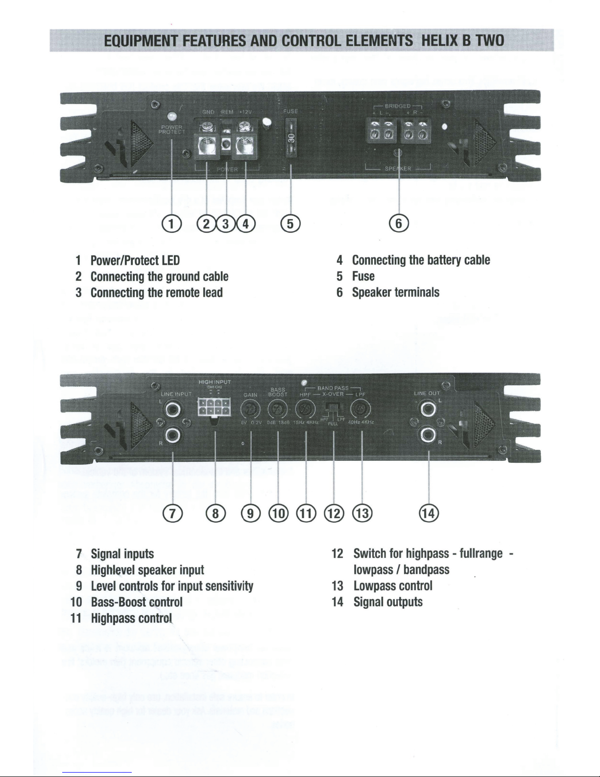
EQUIPMENT
FEATURES
AND
CONTROL
ELEMENTS
HELIX
TWO
B
Power/Protect
1
Connecting
2
Connecting
3
LED
the
the
ground
remote
cable
lead
Connecting
4
Fuse
5
Speaker
6
battery
the
terminals
cable
Signal
7
Highlevel
8
Level
9
Bass-Boost
0
1
Highpass
11
inputs
speaker
controls
control
control
for
input
input
sensitivity
Switch
12
lowpass
Lowpass
13
Signal
14
highpass
for
bandpass
I
control
outputs
fullrange
-
-
Page 4

1
Power/Protect
The
Power/Protect
of
the
amplifier.
ready
for
operation.
A
red
LED
indicates
A
malfunction
TWO
is
equipped
protections
overlow
impedance
Please
cuits,
temperature.
and
repair
and
the
2
Connecting
The
ground
terminal
vehicle)
chassis,
residues.
3
Connecting
The
antenna
This
the
amplifier
shut
and
undervoltage,
check
wrong
connections,
If
has
to
be
service.
purchase
ground
cable
reference
of
the
or
to
1
i.e.
an
Recommended
remote
lead
(aerial
is
only
activated
is
LED
LED
A
green
that
may
have
with
off
the
and
false
for
connecting
the
amplifier
send
to
A
detailed
receipt
the
ground
should
point
battery
a
bright
area
the
remote
is
which
should
positive)
if
switched
indicates
LED
shows
a
malfunction
different
different
amplifier
causes
protective
in
short-circuit
connection.
failures
wrong
adjustments
does
not
your
local
description
has
to
be
cable
be
connected
(this
is
located
grounded
bare-metal
cross
has
been
section:
at
location
lead
be
connected
output
the
on
head
and
of
unit
off
the
operating
that
the
amplifier
has
occurred.
as
the
circuits.
case
of
overheating,
on
loudspeakers,
such
as
turn
on
authorized
of
the
malfunction
attached.
to
where
the
the
metal
on
cleaned
min.
12
to
the
the
head
unit
is
switched
with
the
head
state
is
HELIX
B
These
short
-cir-
and
over-
it
is
defect
dealer
for
a
central
negative
body
of
the
the
vehicle
of
all
paint
2
mm
•
automatic
(radio).
ON.
Thus
unit.
The
impedance
2
Ohms.
In
the
amplifier.
7
Signal
The
can
puts
8
Highlevel
The
speaker
speaker
We
with
harness
9
Level
These
of
the
nected
and
ming.
1
0
To
dB
inputs
HELIX
be
connected
of
the
HELIX
inputs.
outputs
recommend
the
enclosed
(optional).
controls
controls
individual
head
are
solely
The
Bass-Boost
raise
the
per
this
case
B
TWO
control
speaker
B
TWO
They
of
can
channels
unit.
intended
control
control
bass
channel
the
protection
is
equipped
with
the
pre-amplifier
device
(head
input
is
equipped
can
be
the
head
to
operate
connecting
for
input
sensitivity
be
used
to
to
the
These
controls
for
the
range
extends
signal
from
should
with
unit,
with
directly
unit.
the
cable
match
output
are
purpose
from
0
to
18
not
be
lower
electronics
two
RCA
shut
inputs.
outputs
processor
two
extra
connected
highlevel
or
the
voltage
not
200
dB
input
with
a
HELIX
input
of
volume
of
sensitivity
mV
to
at
45
Hz.
than
down
They
I
line-out-
etc.).
highlevel
to
the
only
wire
sensitivity
the
con-
controls
trim-
6
V.
4
Connecting
Connect
the
5
The
equipment
tected
battery
value
6
To
Never
ground.
ker
and
total
most
the
battery.
Fuse
input
fuse
fault,
by
a
(max.
for
the
Speaker
connect
the
connect
It
damages
systems
minus
to
loss
of
speakers.
the
battery
+
12
V
power
Recommended
provides
i.e.
further
line
distance
HELIX
B
the
system
fuse
from
TWO
cable
cable
cross
protection
battery:
is
terminals
speaker
the
are
correctly
minus.
bass
cables.
loudspeaker
your
amplifier.
connected
Exchanging
reproduction.
to
the
section:
must
located
30
1 x
30
Amperes.
See
figures
cables
Ensure
(phase),
plus
The
plus
positive
min.
against
be
additionally
in
the
vicinity
em
I
12
on
with
the
that
the
i.e.
and
minus
pole
is
terminal
2
12
mm
•
an
internal
pro-
of
).
The
page.
chassis
the
fuse
11
next
car
loudspea-
plus
to
plus
causes
indicated
on
of
a
20 30
11
To
adjust
dB
Q
•
_
t----#<I
5
/!
-10
--·--··--~-----+···
-15
booooooool......._
10
45
0
dB
Highpass
the
crossover
I
'
L
+r--:--H
1
_/
·--
·
·
··
>
·
····
»'
:
_,/
_._....~~
15
20
0
15Hz
100 200 300 500
18
dB
control
frequency
:
~1
;
~--"-
···+·•··
·
i··
50
!
•
I ·' '
·
variabel
,'
·
•
·
·H·
···
··
--·1··+······
·
··
'
/
--""-_,;-c.
100
200
from
15
·
·i
»!
,'
_..,_..__
500
,.
-
L'
;,
..
;
....
+
·········
1K
•·--
"""""'-_........_,
~~
·
·
····
·•--··l··
Hz
to
4000
i.l
__,...,.
~
_
1
y:
+
......
,
......
t
..
1/1
: ..
2K
5K
\S)
4kHz
-~
Hz
-;+
~"'*"
.
-
Hz
Page 5

Switch
12
highpass
switch
To
range
full
this
If
frequency
switch
At
crossover
switch
At
always
high
As
bandpass
Caution!
crossover
octaves
2
That
highpass
Hz.
80
a
If
pass
high
counter-clockwise
for
fullrange
-
internal
the
or
(linear)
set
is
switch
the
for
position
active.
not
is
position
That
active.
and
(11)
pass
between
avoid
To
frequencies
building
when
the
means:
If
should
=
octave
(1
subwoofer
is
control
lowpass
on
highpass
FULL
LPF
means
15Hz
lost
a
lowpass
be
double
connected
(11)
to
lowpass
-
frequency
active
bandpass.
I
(highpass),
HPF
can
(fullrange)
(lowpass
bandpass
a
lowpass
(13)
4000Hz
and
sound
of
high-
of
bandpass.
a
signal
adjusted
frequency
variable
as
get
to
Hz
15
I
crossover
adjusted
be
the
bandpass)
I
adjusted
are
can
pressure
lowpass
and
adjusted
is
octaves
2
or
recommend
we
subsonic
subsonic
a
bandpass
highpass,
to
crossover
exact
the
control
with
internal
built
is
frequency
highpass
the
any
in
every
adjusted.
be
sure
make
separated
are
320
to
on
lower
frequency)
half
to
or
filter
filter.
11.
is
.
case
desired
the
that
of
the
Hz
approx.
the
use
it
turn
Lowpass
13
adjust
To
lowpass:
dB
'
t -
-5
~
-
--
...
.
i
-10
15
-
14
Wide
I
L_._
15
10
Signal
band
20
!
!~
fiers.
control
crossover
the
kHz
- 4
40
~~
\.
~~~~,~~
50
0
40Hz
outputs
range)
(full
frequency
' i
~\!--
\
--
--
.....
.
....
200
100
RCA
l
......
..
>\
',
~
outputs
1
~
500
from
,,
.
~
~-
····.
·
'·
-
to
f\
1
:
1K
Hz
40
!
f
--·
.
..
~
.....
i
\,
l
'.
2K
4kHz
connect
4000
to
5K
other
Hz,
i
Hz
ampli-
Stereo
+ - + -
Channel2
Channel
1
LJD
Channel1
Mono
+
(CH1
CH2
bridged)
Page 6

Output
power
RMS I max.
-
at 4 Ohms
-at 2
Ohms
-
bridged
Frequency
Bass-Boost
Highpass
Lowpass
Bandpass
Total
harmonic
Signal-to-noise
Damping
Input
sensitivity
Input
impedance
Input
impedance
Fuse
............................................................................
Dimensions
Weight
...................................................................
..................................................................
at 4 Ohms
response
............................................................
..............................................................
.....................................................................
.................................................................
.................................................................
.................................................................
factor
distortion
ratio
............................................................................
................................................................
.....................................................................
.....................................................................
high
level
................................................................
RCA
..................................................................
(H
x W x
D)
..............................................................
...............................
,
..........................................
2 x
80 I 160
2 x
120 I 240
1 x
200 I 400
1 0
Hz -30.000
0 15 -4.000
40 -4.000
15 -4.000
1 x
2 x
3.5
18
dB I 45
Hz
adjustable
Hz
adjustable
Hz
adjustable
<
0,03
>
0.2
-6
1
kOhms
22
kOhms
30
Amperes
13 x 9.85
kg I 7.7
Watts
Watts
Watts
Hz
Hz
%
95
dB
200
Volts
11
lbs
The
limited
Failures
are
Please
proof
or
not
covered
return
of
purchase
Technical
reserved!
For
damages
handling
All
Number
Thereby
vehicles
errors
HELIX
and
these
inside
warranty
damages
by
the
complies
caused
the
warranty.
defective
by
product
and a detailed
specifications
on
of
amplifiers
the
the
are
subject
vehicle
device,
are
tagged
and
we
also a CE-Certification
devices
the
are
European
Union
certified
with
legal
overload
or
only
malfunction
to
change!
the
device,
cannot
with
assume
an
mark.
for a use
(EU).
regulations.
improper
use
with a valid
description.
Errors
are
caused
by
liability.
E-Certification
inside
Page 7

AUDIOTEC
FISCHER
Gewerbegebiet
Tel.:
E-mail:
helix@audiotec-fischer.com
+49
Lake
29
{0)
Audiotec
Hiinegraben
•
II
88
72-97
Fischer
Fax:
0 •
Internet:
•
GmbH
D-57392
•
26
{0)
+49
www.audiotec-fischer.com
Schmallenberg
88 88
72-97
29
 Loading...