

Page 1
BEDIENUNGSANLEITUNGTUNG
INSTRUCTION MANUAL
MADE IN GERMANY by
Page 2

DEUTSCH
2
Sehr geehrter Kunde,
wir gratulieren Ihnen zum Kauf dieser hochwertigen
HELIX-Endstufe aus deutscher Fertigung. Diese neue
Generation von Verstärkern der Competition Serie
wurde nach neuesten technischen Erkennt
nissen entwickelt und zeichnet sich durch hervorragende
Verarbeitung und überzeugende Technologie aus. Nach
mehr als 23 Jahren Erfahrung in der Erforschung und
Entwicklung von Audiokomponenten setzt sie neue
Maßstäbe. Das ansprechende typische HELIX Design
macht sie zu einer außergewöhnlichen, wertvollen
Endstufe der absoluten Spitzenklasse. Viel Freude an
diesem Produkt wünscht Ihnen das Team von
AUDIOTEC FISCHER
Allgemeines zum Einbau von HELIX-Verstärkern
Um alle Möglichkeiten optimal ausschöpfen zu können,
lesen Sie bitte sorgfältig die nachfolgenden Installationshinweise. Wir garantieren, dass jedes Gerät vor
Versand auf seinen einwandfreien Zustand überprüft
wurde.
Vor Beginn der Installation unterbrechen Sie den
Minusanschluß der Autobatterie. Wir empfehlen Ihnen
die Installation von einem Einbauspezialisten vornehmen zu lassen, da der Nachweis eines fachgerechten
Einbaus und Anschlusses des Gerätes Voraussetzung für
die Garantieleistungen sind.
Installieren Sie Ihren Verstärker an einer trockenen
Stelle im Auto und vergewissern Sie sich, dass der Verstärker am Montageort genügend Kühlung erhält. Montieren Sie das Gerät nicht in zu kleine, abgeschlossene
Gehäuse ohne Luftzirkulation oder in der Nähe von wärmeabstrahlenden Teilen oder elektronischen Steuerungen des Fahrzeuges.
Im Sinne der Unfallsicherheit muß der Verstärker professionell befestigt werden. Dieses geschieht über die 4
beiliegenden Schrauben, die in eine Montagefläche eingeschraubt werden, die genügend Halt bieten muss.
Bevor Sie die Schrauben im Montagefeld befestigen,
vergewissern Sie sich, daß keine elektrischen Kabel und
Komponenten, hydraulische Bremsleitungen, der
Benzintank etc. dahinter verborgen sind. Diese könnten
sonst beschädigt werden. Achten Sie darauf, daß solche
Teile sich auch in der doppelten Wandverkleidung verbergen können.
Anschluß der Verstärker
Der Verstärker darf nur in Kraftfahrzeuge eingebaut
werden, die den 12V Minuspol an Masse haben. Bei
anderen Systemen können der Verstärker und die elektrische Anlage des Kfz beschädigt werden.
Die Plusleitung für die gesamte Anlage sollte in einem
Abstand von max. 30 cm von der Batterie mit einer
Hauptsicherung abgesichert werden. Der Wert der
Sicherung errechnet sich aus der maximalen Stromaufnahme der Car-Hifi Anlage. Die Kabelverbindungen
müssen so verlegt sein, daß keine Klemm-, Quetschoder Bruchgefahr besteht. Bei scharfen Kanten
(Blechdurchführungen) müssen alle Kabel gegen
Durchscheuern gepolstert sein.
Ferner dürfen die Stromversorgungskabel niemals mit
Zuleitungen zu Vorrichtungen des Kfz (Lüftermotoren,
Brandkontrollmodulen, Benzinleitungen etc.) verlegt
werden.
Um eine sichere Installation zu gewährleisten, sollte auf
hohe Qualität der verwendeten Anschlussmaterialien
geachtet werden.
25
25
25
24
23
20
25
26
27
22
28
29
19
31
18
21
30
32
9
8
7
6
5
4
3
2
1
14
13
12
11
10
17
16
15
1
2
1
2
1
2
1
2
2
1
3
2
1
3
2
1
3
2
1
3
Anschluss Remoteleitung
Anschluss Batteriekabel
Anschluss Massekabel
Sicherungen
Sicherungsfunktionsanzeige
Eingangssignalschalter für die Eingänge C und D
Signaleingänge
Levelregler für
Eingangsempfindlichkeit
CPS-Colour Protection System
Umschalter für HP/Lin/TP der Kanäle
A und B
Umschalter für HP/Lin/TP der Kanäle
C und D
Frequenzwahlbereichsschalter
Frequenzeinstellregler
Lautsprecheranschlussklemmen
für die Kanäle A und B
Lautsprecheranschlussklemmen
für die Kanäle C und D
Pegelregler zur Anhebung der Mittenfrequenzen
Einstellung der Mittenfrequenzen
Mono/Stereo Schalter
Umschalter für vollaktiven Betriebsmodus
Levelregler für die Kanäle C und D
im vollaktivem Betriebsmodus
1
2
3
4
5
6
7-10
11-14
15-17
18
19
20-21
22-23
24
25
26
27
28-29
30
31-32
Page 3
3
1 Anschluß Remoteleitung
Die Remoteleitung wird mit dem automatischen
Antennenanschluß des Steuergerätes (Radio) verbunden.
Dieser ist nur aktiviert, wenn das Steuergerät EINgeschaltet ist. Somit wird der Verstärker mit dem
Steuergerät ein-und ausgeschaltet.
2 Anschluß Batteriekabel
Das +12V Versorgungskabel ist am Pluspol der Batterie
anzuschließen. Empfohlener Querschnitt: min. 16 mm
2
.
3 Anschluß Massekabel
Das Massekabel sollte am zentralen Massepunkt (dieser
befindet sich dort wo der Minuspol der Batterie zum
Metallchassis des Kfz geerdet ist) oder an einer blanken,
von Lackresten befreiten Stelle des Kfz-Chassis angeschlossen werden.
4 Sicherungen
Die Eingangssicherungen sind parallel geschaltet und
schützen vor einem geräteinternen Fehler, d.h. die
Anlage muß mit einer zusätzlichen Sicherung in Nähe
der Batterie (max. 30 cm entfernt) abgesichert werden.
Die Sicherungswerte betragen 3 x 25 Ampere und müssen beide installiert sein, da der Verstärker mit 75
Ampère (3 x 25 A) abgesichert ist.
5 Sicherungsfunktionsanzeige
Sollten die Sicherungen (4) durch eine Fehlfunktion zerstört werden, wird dieses durch das Aufleuchten der
roten LED angezeigt. Bei normalem Betrieb bleibt die
LED erloschen.
6 Eingangssignalschalter für die Eingänge C und D
Sollte beim Brückenbetrieb (Dreikanalbetrieb nur möglich, wenn die Kanäle C und D gebrückt werden) der
Kanäle C und D nur ein Monosignal, d.h. eine Cinchleitung zur Verfügung stehen, können die Eingänge mit
Hilfe dieses Schalters (6) auf Schalterstellung 2 verbunden werden. Somit entfällt der Y-Adapter. Auf Schalterstellung 1 sind die Kanäle C und D einzeln anzusteuern.
7- 10 Signaleingänge
Die A4 hat RCA-Anschlüsse zum Kontaktieren von
Cinchkabeln, die mit den Vorverstärkerausgängen der
Line-Outputs des Steuergerätes oder eines
Vorverstärkers z.B. HXE 100 verbunden werden. Diese
Anschlüsse sind vergoldet um eine bessere NF-Übertragung zu gewährleisten.
11 - 14 Levelregler für Eingangsempfindlichkeit
Mit Hilfe dieser Regler kann die Eingangsempfindlichkeit der einzelnen Kanäle A bis D an die Ausgangsspannung des angeschlossenen Steuergerätes angepaßt
werden. Diese Regler sind keine Lautstärkeregler, sondern dienen nur der Anpassung. Der Regelbereich ist
500 mV bis 8 V.
15 - 17 CPS-Color Protection System
Die LEDs zeigen den Betriebszustand der Endstufe an.
Grün (15) = betriebsbereit; gelb(16) = Fehlfunktion der
Endstufe; Kurzschluß am Lautsprecherausgang: rot (17)
= Überhitzung. Sollte die Endstufe wegen Überhitzung
abgeschaltet haben, kann es je nach Umgebungstemperatur einige Zeit dauern, bis sie sich wieder einschaltet.
18 Umschalter für HP/Lin/TP der Kanäle A und B
Zur Umschaltung der internen, aktiven Frequenzweiche
auf Hochpass/ Full Range (Linear) oder Tiefpass der
Kanäle A und B.
19 Umschalter für HP/Lin/TP der Kanäle C und D
zur Umschaltung der internen, aktiven Frequenzweiche
auf Hochpass/ Full Range (Linear) oder Tiefpass der
Kanäle C und D.
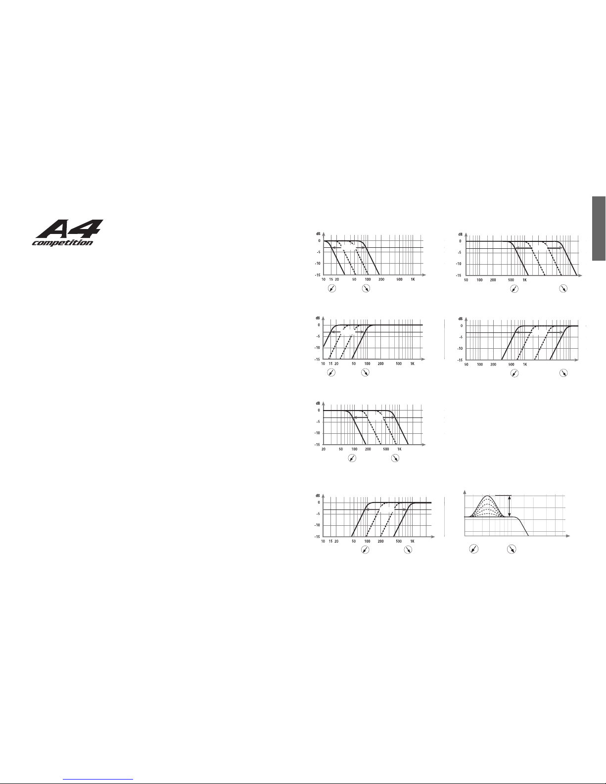
20 - 21 Frequenzwahlbereichsschalter
Mit Hilfe dieses Schalters kann der Regelbereich der
Potentiometer 22 (Kanäle A und B) und 23 (Kanäle C
und D) von 15 Hz bis 90 Hz auf Position 1, von 90 Hz
bis 800 Hz auf Position 2 und von 600 Hz bis 7 kHz auf
Position 3 gestellt werden.
Position 1: Tiefpass
Position 1: Hochpass
Position 2: Tiefpass
Position 2: Hochpass
Position 3: Tiefpass
Position 3: Hochpass
22 - 23 Frequenzeinstellregler
Regler zur Einstellung der Trennfrequenz der Stereokanäle A und B (22) und C und D (23).
24 Lautsprecheranschlußklemmen für Kanäle A u. B
25 Lautsprecheranschlußklemmen für Kanäle C u. D
26 Bassboost - Pegelregler zur Anhebung der
Mittenfrequenzen
Mit Hilfe des Reglers Nr. 26 kann die durch Regler Nr.
27 eingestellte Mittenfrequenz von 0 bis 9 dB angehoben werden, wenn der Schalter 19 auf HP oder LP steht.
15 Hz 90 Hz
Hz
variabel
15 Hz 90 Hz
Hz
variabel
90 Hz 800 Hz
Hz
variabel
90 Hz 800 Hz
Hz
variabel
Hz5K2K
600 Hz
7 kHz
variabel
2K 5K Hz
600 Hz 7 kHz
variabel
0 dB
9 dB
50050 100 200 30020 30
variabel
Hz
dB
DEUTSCH
Page 4
4
27 Einstellung der Mittenfrequenzen
Mit Hilfe des Reglers Nr. 27 kann auf dem Band des eingestellten Tiefpasses (siehe Regler Nr. 23) eine
Frequenz von 30 - 120 Hz gewählt werden, die mit Hilfe
des Reglers Nr. 26 von 0 bis 9dB angehoben werden
kann. Dieses ist sinnvoll, wenn bestimmte Frequenzen
des Subwoofers hervorgehoben (Kickbass) oder korrigiert werden sollen.
28 - 29 Mono/Stereo Schalter
Mit diesen Schaltern kann die Betriebsart der Endstufe
festgelegt werden.
4-Kanal: Nutzen Sie den Verstärker im 4-Kanalbetrieb,
so müssen sich beide Schalter in Stereo, Position 1,
befinden.
3-Kanal: Nutzen Sie den Verstärker im 3-Kanalbetrieb
(Frontsystem/Subwoofer), stellen Sie den Schalter 28
der Kanäle A und B für das Frontsystem auf Stereo,
Position 1, und den Schalter 29 der Kanäle C und D auf
Mono, Position 2. Achtung! Im 3-Kanalbetrieb müs-
sen die Kanäle C und D gebrückt werden, da die
Kanäle A und B sich nur im 2-Kanalmodus brücken
lassen. So ist gewährleistet das die Kanäle C und D
als Monokanal für den Subwooferbetrieb benutzt
werden, da diesem auch die Bassanhebung zugeordnet ist. Für den gebrückten Kanal müssen beide
Eingänge (9 und 10) belegt werden, da sich aus beiden
Kanälen ein Summensignal bildet. Sollte für den
Subwoofer nur ein Monosignal zur Verfügung stehen,
muß mit Hilfe des Schalters 6 das Signal auf beide
Eingänge verteilt, oder ein Y-Adapter verwendet werden.
2-Kanal: Nutzen Sie den Verstärker im 2-Kanalbetrieb,
stellen Sie den Schalter 28 der Kanäle A und B und den
Schalter 29 der Kanäle C und D auf Mono, Position 2.
Achtung! Bevor Sie auf 2-Kanalbetrieb schalten
müssen zuerst die Kanäle C un D gebrückt werden.
Sollten sich die Kanale A und B nicht brücken lassen
überprüfen sie, ob der Schalter 29 der Kanäle C und
D auf Position 2 (Mono) geschaltet ist. Beim 2-
Kanalbetrieb müssen nur die Eingänge A und B belegt
werden, wobei das Signal des Eingangs A für den
gebrückten Kanal A und B und das Signal des
Eingangs B für den gebrückten Kanal C und D ver-
wendet wird.
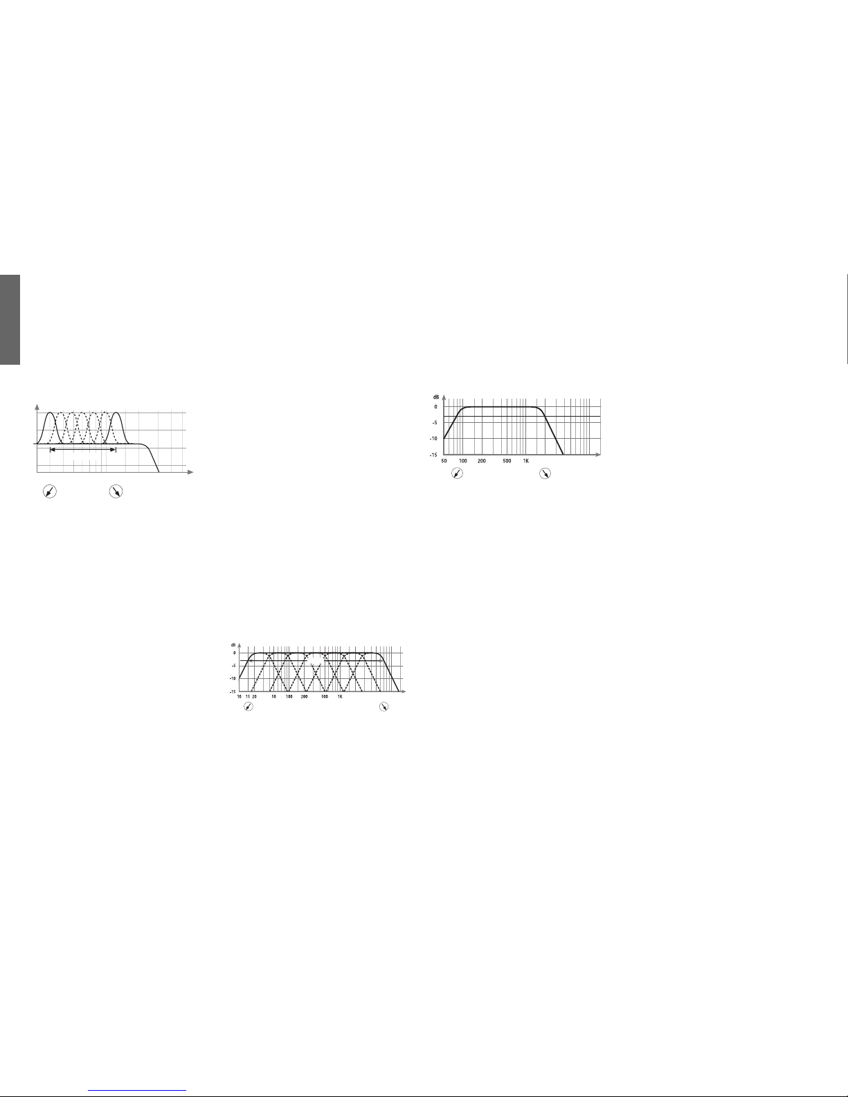
30 Vollaktiver Betriebsmodus
Mit Hilfe des Schalters 30 kann der Verstärker A4 zum
Aufbau eines vollaktiven Systems genutzt werden.
Hierzu wird der Schalter auf Position 2 gestellt. In diesem Fall werden von den Eingängen A und B (nur diese
können in diesem Modus benutzt werden) die
Frequenzen für die Kanäle A und B eingestellt. Der
Tiefpass des Signals, der mit Hilfe des Reglers 22 eingestellten Frequenz für die Kanäle A und B, wird unabhängig von der Stellung des Schalters 18 (HP/Lin/TP)
zu den Kanälen C und D weitergeleitet. Hierbei ist es
egal ob die Kanäle A und B als Hochpass, Linear oder
als Tiefpass benutzt werden, es wird immer nur das
Tiefpass-Signal zu den Kanälen C und D weitergeleitet. Für die Einstellung der benötigten Frequenz des
weiterzuleitenden Signals erfolgt die Justierung mit
Hilfe des Reglers 22. Aufgrund der Tiefpassweiterschaltung nach den Kanälen C und D kann mit diesen
ein Bandpass in einer Bandbreite von 15 Hz bis 7 kHz
gebildet werden.
Beispiel 1: Wenn die Kanäle A und B linear (Full Range)
betrieben werden, so stehen den Kanälen C und D die
Frequenzen als Tiefpass zur Verfügung, die mit Hilfe des
Reglers 22 eingestellt werden.
20020 30 50 100 300 500
dB
Hz
variabel
Beispiel 2: Wenn die Kanäle A und B als Hochpass mit
z.B. 2 kHz betrieben werden, so stehen den Kanälen C
und D die Frequenzen bis 2 kHz zur Verfügung. Schaltet
man diese nun als Hochpass z.B. 80 Hz, so entsteht für
die Kanäle C und D ein Bandpass von 80 Hz bis 2 kHz.
Bandpass 80 Hz bis 2kHz
31 - 32 Levelregler für die Kanäle C und D im vollaktivem Betriebsmodus
Mit Hilfe der Raaaegler 31 (Kanal C) und 32 (Kanal D)
kann der Ausgangspegel der Kanäle C und D im vollaktiven 4 oder 3 Kanal-Betriebsmodus den Kanälen A und
B um +/- 6dB angepasst werden. Im 3-Kanalmodus
(Mono C/D) müssen beide Regler (31/32) bedient werden. Im 2-Kanalmodus sind diese Regler nicht akti-
viert!
Achtung!: Bitte vergewissern Sie sich, dass im vollaktiven Betriebsmodus beim Aufbau eines Bandpasses auf den Kanälen C/D die Übernahmefrequenzen von Hoch- und Tiefpass 2 Oktaven auseinander
liegen, um einen Pegelverlust zu vermeiden!
Das heisst: Wird das Tiefpasssignal der Kanäle A/B zu
den Kanälen C/D weitergeleitet, so sollte der Hochpass
der Kanäle C/D 2 Oktaven tiefer liegen. Beispiel:
Tiefpassweiterleitung 320 Hz - Hochpasseinstellung bei
den Kanälen C/D = 80 Hz. ( 1 Oktave = Frequenzverdopplung oder Frequenzhalbierung)
Wichtige Hinweise!
Der Verstärker A4 ist mit einem temperaturgesteuerten
intelligenten Netzteil ausgestattet. Diese neuentwickelte
Elektronik ermöglicht, dass der Verstärker bei sehr hohen Temperaturen die Ausgangsleistung reduziert, um
ihn vor Zerstörung oder Abschaltung durch Überhitzung zu schützen. Diese Leistungsreduzierung ist im
normalem Gebrauch nicht zu hören, weil sie sich nur
bei Dynamikspitzen bemerkbar macht und sich der Verstärker nur bei extremer Belastungen und sehr hohen
Außentemperaturen so stark erwärmt. Sollte sich der
Verstärker aufgrund Überhitzung (größer 95° Celsius)
ausschalten, kann es einige Minuten dauern bis sich der
Verstärker wieder einschaltet.
Ebenfalls verzögert sich das Einschalten des Verstärkers
aufgrund der integrierten Sicherheitselektronik um ca.
3 - 4 Sekunden. Dieses geschieht aufgrund der Erfassung aller betriebssicherheitsrelevanten Spannungen,
die einen einwandfreien Betrieb garantieren.
Außerdem sind im Verstärker verschiedene elektronische Schutzschaltungen intergriert, die bei Überlastung,
Überhitzung, Kurzschluss an den Lautsprechern, aber
auch bei zu niederohmigem Betrieb oder mangelhafter
Stromversorgung den Verstärker abschalten. Dieses
wird durch verschiedene LEDs angezeigt. (Siehe CPS
System Punkt 15 -17) Prüfen Sie in diesem Fall alle Anschlüsse auf Fehler, wie z.B Kurzschlüsse, fehlerhafte
Verbindungen oder Falscheinstellungen und Übertemperatur. Sollte sich der Verstärker nach der Beseitigung
der Fehlerquelle nicht wieder einschalten lassen, liegt
ein Defekt vor und das Gerät muß mit Fehlerbeschreibung und Kaufbeleg zur Reparatur an den Händler
zurückgegeben werden.
Verbinden Sie niemals die Lautsprecherleitungen
mit der Kfz-Masse (Fahrzeugkarosserie). Dieses kann
Ihren Verstärker zerstören. Achten Sie darauf, dass
alle Lautsprechersysteme phasenrichtig angeschlossen
sind, d.h. Plus zu Plus und Minus zu Minus. Der Pluspol ist bei den meisten Lautsprechern gekennzeichnet.
Im Auslieferungszustand ist die A4 als 4-Kanal Ve r-
stärker voreingestellt.
Beim Betrieb als 3-Kanal-Endstufe muß in jedem Fall
der Kanal C und D gebrückt (mono) werden, da in den
meisten Fällen der gebrückte Monokanal aufgrund der
höheren Leistung zur Ansteuerung des Subwoofers genutzt wird, und der Bassboost diesen Kanälen zugeordnet ist.
15 Hz
7 kHz
2K 5K 10K Hz
variabel
2K 5K
2 kHz80 Hz
Hz
DEUTSCH
Kanal A
Page 5

DEUTSCH
5
Technische Daten A 4 Competition
Ausgangsleistung pro Kanal an 4 Ohm gemessen an 12 V . . . . . . . . . . . . . . . . . . . . . . . . . . . . . 4 x 60 Watt RMS
Ausgangsleistung pro Kanal an 4 Ohm gemessen an 13,8 V . . . . . . . . . . . . . . . . . . . 4 x 85/150 Watt RMS/Musik
Ausgangsleistung pro Kanal an 2 Ohm gemessen an 13,8 V . . . . . . . . . . . . . . . . . . . 4 x 153/250 Watt RMS/Musik
Ausgangsleistung 1 Kanal gebrückt an 4 Ohm und 2 x 4 Ohm . . . . . 1 x 330/500 und 2 x 85/150 Watt RMS/Musik
Ausgangsleistung 1 Kanal gebrückt an 2 Ohm und 2 x 2 Ohm . . . . 1 x 480/800 und 2 x 125/200Watt RMS/Musik
Frequenzbereich . . . . . . . . . . . . . . . . . . . . . . . . . . . . . . . . . . . . . . . . . . . . . . . . . . . . . . 20 Hz - 20 kHz, +/- 0,3 dB
Bassboost Pegelanhebung . . . . . . . . . . . . . . . . . . . . . . . . . . . . . . . . . . . . . . . . . . . . . . . . . . . . . . . . . . . . . .0 - 9 dB
Bassboost Einstellbereich der Mittenfrequenz . . . . . . . . . . . . . . . . . . . . . . . . . . . . . . . . . . . . . . . . . . . 30 - 120 Hz
Frequenzweiche Regelbereich . . . . . . . . . . . . . . . . . . . . . . . . . . . . . . . . . . . . . . . . . . . . . . . . . . . . . 15 Hz - 7 kHz
Pegelanhebung im 3-Kanalmodus der Kanäle C und D . . . . . . . . . . . . . . . . . . . . . . . . . . . . . . . . . . . . . . .+/- 6 dB
Klirrfaktor . . . . . . . . . . . . . . . . . . . . . . . . . . . . . . . . . . . . . . . . . . . . . . . . . . . . . . . . . . . . . . . . . . . . . . . . < 0,009%
TIM . . . . . . . . . . . . . . . . . . . . . . . . . . . . . . . . . . . . . . . . . . . . . . . . . . . . . . . . . . . . . . . . . . . . . . . . . . . . . < 0,016%
Geräuschspannungsabstand . . . . . . . . . . . . . . . . . . . . . . . . . . . . . . . . . . . . . . . . . . . . . . . . . . . . . . . . . . . > 100 dB
Eingangsimpedanz . . . . . . . . . . . . . . . . . . . . . . . . . . . . . . . . . . . . . . . . . . . . . . . . . . . . . . . . . . . . . . . . . . 10 kOhm
Eingangsempfindlichkeit . . . . . . . . . . . . . . . . . . . . . . . . . . . . . . . . . . . . . . . . . . . . . . . . . . . . . . . . . . 500 mV - 8 V
Sicherung . . . . . . . . . . . . . . . . . . . . . . . . . . . . . . . . . . . . . . . . . . . . . . . . . . . . . . . . . . . . . . . . . . . . .3 x 25 Ampere
Abmessungen (H x B x T) in mm . . . . . . . . . . . . . . . . . . . . . . . . . . . . . . . . . . . . . . . . . . . . . . . . . . 35 x 240 x 432
Gewicht netto . . . . . . . . . . . . . . . . . . . . . . . . . . . . . . . . . . . . . . . . . . . . . . . . . . . . . . . . . . . . . . . . . . . . . . . . 4,7 kg
Wichtige Lautsprecher Anschlussinformationen
Die A4 verfügt über 4 integrierte Leistungsver-stärker,
wobei jeder für sich 1 Ohm stabil ist. Das heißt, das an
jedem Kanal eine Lautsprecher-impedanz von 1 Ohm
angeschlossen werden kann. Beim Brückenbetrieb
arbeiten je zwei Verstärker zusammengeschaltet als ein
Kanal. Hierbei muss beachtet werden, dass jeder Kanal
die Hälfte der angeschlossenen Impedanz verarbeiten
muss. Wenn z.B. ein 4 Ohm Lautsprecher an eine
gebrückte Endstufe angeschlossen wird, so sieht jeder
einzelne Kanal 2 Ohm, bei einem 2 Ohm Lautsprecher
also 1 Ohm. Also ist 2 Ohm die untere Impedanzgrenze
die an einem gebrückten Kanalpaar angeschlossen werden kann, da jeder Kanal für sich nur 1 Ohm stabil ist.
Auch sollten nicht alle Kanäle mit einer Impedanz von
1 Ohm betrieben werden, da sonst der totale Aufnahmestrom zu hoch würde. In diesem Fall kann es sein, dass
die berechnete Gesamtleistung des Verstärkers überschritten wird und die Eingangssicherungen oder sogar
der Verstärker zerstört wird. Zusätzlich macht es auch
nicht viel Sinn 1 Ohm auf allen Kanälen anzuschließen,
da die Gesamtverlustleistung viel zu hoch wäre, d.h. die
Leistung wird nicht mehr vom Lautsprecher umgesetzt,
sondern in Wärme innerhalb des Verstärkers, an den
Anschlüssen und Kabeln.
Um einen sicheren Betrieb der A4 zu gewährleisten gibt
es zwei einfache Regeln die man beachten sollte.
1. Die Summe aller angeschlossen Lautsprecherimpedanzen (Gesamtimpedanz) an allen 4 Kanälen
sollte 6 Ohm nicht unterschreiten. Das bedeutet, egal
ob ein Kanalpaar gebrückt ist oder nicht sollte die
Gesamtimpedanz 6 Ohm nicht unterschreiten. Hier ein
paar Beispiele:
4 x 1,5 Ohm oder
1 x 2 Ohm (gebrückt)+ 2 x 2 Ohm oder
2 x 1Ohm + 1 x 4 Ohm (gebrückt) oder
2 x 3 Ohm (gebrückt) usw.
Bei all diesen Beispielen wird die Gesamtimpedanz von
6 Ohm nicht unterschritten. Sollten jedoch z.B. je zwei
2 Ohm Woofer (4 Ohm gesamt) an zwei gebrückte
Kanäle oder vier 1 Ohm Lautsprecher (4 Ohm gesamt)
an jedem Kanal angeschlossen werden und somit die
Gesamtimpedanz unter 6 Ohm kommen, kann es sein,
dass der Verstärker abschaltet, die Sicherungen durchbrennen oder im schlimmsten Fall der Verstärker zerstört
wird.
2. Die Impedanz pro Kanal darf 1 Ohm nicht unterschreiten.
Wir garantieren Ihnen einen unbegrenzten Hörgenuss
mit absolut ausreichender Leistung bei Beachtung dieser
wertvollen Informationen.
Helix Produkte geniessen aufgrund ihres hohen
Qualitätsniveaus international einen ausgezeichneten
Ruf. Daher gewähren wir eine Garantiezeit von 2 Jahren.
Die Produkte werden während der gesamten Fertigung
ständig kontrolliert und geprüft. Bitte beachten Sie im
Servicefall folgende Hinweise:
1. Die 2-jährige Garantiezeit beginnt mit Kauf des
Produktes und gilt nur für den Erstbesitzer.
2. Während der Garantiezeit beseitigen wir etwaige
Mängel, die nachweislich auf Material-oder Fabrikationsfehler beruhen, nach unserer Wahl durch Austausch oder Nachbesserung der defekten Teile.
Weitergehende Ansprüche, insbesondere auf
Minderung, Wandlung, Schadenersatz oder
Folgeschäden sind ausgeschlossen. Ersetzte Teile
gehen in das Eigentum von Audiotec Fischer über.
Die Garantiezeit wird von einer Garantieleistung
durch uns nicht berührt.
3. Am Produkt dürfen keine unsachgemäßen Eingriffe
vorgenommen worden sein.
4. Bei Inanspruchnahme der Garantie wenden Sie sich
bitte zuerst an Ihren Fachhändler. Sollte es notwendig
sein, das Produkt an uns einzuschicken, so beachten
Sie bitte folgende Hinweise:
a) Das Produkt muss in einwandfreier Original-
verpackung verschickt werden
b)
Die Garantiekarte muss ausgefüllt dem Produkt beiligen
c) Das Produkt muss frachtfrei zugestellt werden, d.h.
Porto und Risiko gehen zu Ihren Lasten
d) Die Kaufquittung muss beiliegen
5. Von der Garantie ausgenommen sind:
a) Transportschäden, sichtbar oder unsichtbar (Reklama-
tionen für solche Schäden müssen umgehend bei der
Transportfirma eingereicht werden)
b) Kratzer in Metallteilen, Frontabdeckungen usw.
Diese Defekte müssen innerhalb von 5 Tagen nach
Kauf direkt bei Ihrem Händler reklamiert werden.
c) Fehler, die durch fehlerhafte Aufstellung, falschen
Anschluss, unsachgemäße Bedienung, Beanspruchung
oder äußere gewaltsame Einwirkung entstanden sind.
d) Unsachgemäß reparierte oder geänderte Geräte, die
von anderer Seite als von uns geöffnet wurden.
e) Folgeschäden an fremden Geräten
f) Kostenerstattung bei Schadensbehebung durch Dritte
ohne unser vorheriges Einverständnis
g) Geräte mit entfernten Typenschildern oder Serien-
nummern.
Garantiebestimmungen
Beim Betrieb als 2-Kanal-Endstufe können die Kanäle
A und B nur gebrückt werden, nachdem die Kanäle C
und D bereits gebrückt wurden.
Page 6

DEUTSCH
4-Kanalbetrieb
3-Kanalbetrieb
Achtung! Im 3-Kanalbetrieb müssen die Kanäle C und D gebrückt werden, da die Kanäle A und B sich nur im
2-Kanalmodus brücken lassen. So ist gewährleistet das die Kanäle C und D als Monokanal für den
Subwooferbetrieb benutzt werden, da diesem auch die Bassanhebung zugeordnet ist.
2-Kanalbetrieb
Achtung! Für den 2-Kanalbetrieb müssen zuerst die Kanäle C un D gebrückt werden. Sollten sich die Kanäle
A und B nicht brücken lassen, überprüfen Sie, ob der Schalter 29 der Kanäle C und D auf bridged “on” steht.
Vollaktiver Betriebsmodus
Mit Hilfe des Schalters 30 kann der Verstärker A4 zum Aufbau eines vollaktiven Systems genutzt werden.
Hierzu wird der Schalter 30 “Full Active Operating Mode”auf Position “on” gestellt. Es wird immer nur das
Tiefpass-Signal zu den Kanälen C und D weitergeleitet.
Kanal A
Kanal B
Kanal C
Kanal D
Kanal A
Kanal B
Kanal A und B gebrückt/ Mono
Kanal C und D gebrückt/ Mono
Kanal C und D gebrückt/ Mono
Schalter 29
Schalter 30
“Channel C/D bridged” auf “on”
Page 7

6
Dear Customer,
congratulations on your purchase of this high-quality HELIX amplifier, made in Germany. The new
Helix competition series amplifiers highlights best
quality, excellent manufacturing and state-of-theart technology. After 23 years of experiences in
the research & development of audio products this
amplifier generation sets new standards. The
attractive typical Helix design makes this amplifier
to an outstanding and top of the class product.
We wish you many hours of enjoyment with your
new HELIX amplifier.
Yours
AUDIOTEC FISCHER Team
General installation instructions for HELIX
amplifiers
To find out how HELIX amplifiers work best for
you, read this manual carefully and follow the
instructions for installation. We guarantee that this
product has been checked for proper functioning
before shipping.
Before you start installation, disconnect the car
battery at the minus pole. We would urge you to
have the installation work carried out by a specialist as verification of correct installation and
connection of the unit is a prerequisite for warranty cover of the HELIX amplifier.
Install your amplifier at a dry location where there
is sufficient air circulation to ensure adequate cooling of the equipment. For safety reasons, the
amplifier must be secured in a professional manner. This is performed by means of four fixing screws screwed into a mounting surface offering sufficient retention and stability.
Before drilling the holes for the screws, carefully
examine the area around the installation position
and make sure that there are no electrical cables or
components, hydraulic brake lines or any part of
the petrol tank located behind the mounting surface - otherwise these could be damaged. You should
be aware of the fact that such components may
also be concealed in the double-skin trim
panels/mouldings.
General instruction for connecting the amplifiers
The HELIX amplifiers may only be installed in
motor vehicles which have a 12-volt minus pole
connected to the chassis ground. Any other system
could cause damage to the amplifier and the electrical system of the vehicle.
The plus cable from the battery for the complete
system should be provided with a main fuse at a
distance of max. 30 cm from the battery. The value
of the fuse is calculated from the maximum total
current input of the car audio system.
Install the cabling in a manner which precludes
any danger of the leads being exposed to shear,
crushing or rupture forces. If there are sharp edges
in the vicinity (e.g. holes in the bodywork) all
cables must be cushioned and protected to prevent
fraying.
Never lay the power supply cables adjacent to
leads and lines connecting other vehicle equipment
(fan motors, fire detection modules, gas lines etc.).
In order to ensure safe installation, use only highquality connections and materials. Ask your dealer
for high quality accessories.
25
25
25
24
23
20
25
26
27
22
28
29
19
31
18
21
30
32
9
8
7
6
5
4
3
2
1
14
13
12
11
10
17
16
15
1
2
1
2
1
2
1
2
2
1
3
2
1
3
2
1
3
2
1
3
Connecting the remote lead
Connecting the battery cable
Connecting the ground cable
Fuses
Fuse Function Indication
Input Signal Switch for Inputs C
and D
Signal input
Level controls for input sensitivity
CPS-Colour Protection System
Switch for HP/ Linear/ LP of channel A and B
Switch for HP/ Linear/ LP of channel C and D
Control for frequency range
Control for level adjustment
Speaker terminal for channel A
and B
Speaker terminal for channel C
and D
Control to raise the center frequency
Adjustment of center frequencies
Mono/ stereo switch
Full active operating mode
Level control for channel C and D
in full active operating mode
1
2
3
4
5
6
7-10
11-14
15-17
18
19
20-21
22-23
24
25
26
27
28-29
30
31-32
ENGLISH
Page 8

ENGLISH
7
1 Connecting the remote lead
The remote lead is connected to the automatic antenna
(aerial positive) output of the head unit (radio). This is
only activated if the head unit is switched ON. Thus the
amplifier is switched on and off with the head unit.
2 Connecting the battery cable
Connect the +12 V power cable to the positive terminal
of the battery. Recommended cross section: min.
16mm_.
3 Connecting the ground cable
The ground cable should be connected to a central ground reference point (this is located where the negative
terminal of the battery is grounded at the metal body of
the vehicle), or to a bright bare-metal location on the
vehicle chassis, i.e. an area which has been cleaned of all
paint residues.
4 Fuses
The input fuses are connected in parallel and provide
protection against an internal equipment fault, i.e. the
system must be additionally protected by a further line
fuse located in the vicinity of the battery (max. distance
from battery: 30 cm). The fuse ratings are 3 x 25 amperes, and both must be installed as the amplifier protection rating is 75 amperes (3 x 25 A).
5 Fuse Function Indication
If the fuses (4) are destroyed due to malfunction the red
LED illuminates. In normal operation the LED turns off.
6 Input Signal Switch for Inputs C and D
If there is only a mono signal in bridged mode on channel C and D the inputs can be connected with switch (6)
on position 2. A Y-adapter is not necessary. Trimode is
only possible when channels C and D are bridged. Drive
channel C and D individual on position 1.
7-10 Signal input
The A4 Competition has RCA connectors for RCA
cables that can be connected with the pre-amplifier output of the line-outputs of the headunit or of a pre-amplifier i.g. HXE 100. This connectors are gold-plated to
ensure a better signal transmission.
11 - 14 Level controls for input sensitivity
These controls can be used to match the input sensitivity of the individual channels - A to D - to the output voltage of the connected head unit. These controls are not
volume controls and are solely intended for the purpose
of sensitivity trimming. The control range extends from
700 mV to 8 V.
15-17 CPS - Color Protection System
This LEDs show the operation mode of the amplifier
green = in operation; yellow = malfunction of the amplifier, short circuit at loudspeaker output; red = overheating
If the amplifier shuts off due to overheating it can take a
while until it turns on again. This depends on the outside temperature.
18 Switch for HP/ Linear/ LP of channel A and B
To switch over the internal active crossover to highpass/
full range (linear) or lowpass of channel A and B
19 Switch for HP/ Linear/ LP of channel C and D
To switch over the internal active crossover to highpass/
full range (linear) or lowpass of channel C and D
20 - 21 Control for frequency range
This control enables to adjust the control range of the
potentiometer 22 (channel A and B) and 23 (channel C
and D) from 15 Hz up to 90 Hz on position 1, from 90
Hz up to 800 Hz on position 2 and from 600 Hz up to 7
kHz on position 3.
Position 1: Lowpass
Position 1: Highpass
Position 2: Lowpass
Position 2: Highpass
Position 3: Lowpass
Position 3: Highpass
22 - 23 Control for level adjustment
Control to adjust the crossover frequency of stereo channel A and B (22) and C and D (23)
24 Speaker terminal for channel A and B
25 Speaker terminal for channel C and D
26 Control to raise the center frequency
This control enables the center frequency set at control
27 to be raised from 0 to 9 dB if the switch 19 is on HP
or LP position.
15 Hz 90 Hz
Hz
variable
15 Hz 90 Hz
Hz
variable
90 Hz 800 Hz
Hz
variable
90 Hz 800 Hz
Hz
variable
Hz5K2K
600 Hz
7 kHz
variable
2K 5K Hz
600 Hz 7 kHz
variable
0 dB
9 dB
50050 100 200 30020 30
variable
Hz
dB
Page 9

8
27 Adjustment of center frequencies
Control 27 can be used to select the frequency from 30120 Hz of the adjusted lowpass (control 23). this can be
enhanced with control 26 from 0 to 9 dB.
It is usefull to emphasize or correct a determined frequency of the subwoofer (kickbass)
28 - 29 Mono/ stereo switch
To set the operating mode of the amplifier.
4-channel: If the amplifier operates in 4-channel mode
both switches have to be set on stereo and position 1
3-channel: If the amplifier is operates in3-channel mode
(frontsystem/ subwoofer) set control 28 of channel A
and B for the frontsystem on stereo, position 1 and control 29 of channel C and D on mono, position 2.
Caution: Channel C and D must be bridged in 3channel mode operation, because channel A and B
can only be bridged in 2-channel mode. It ensures
that channel C and D are used as mono channel for
the subwoofer. Only this channels have bassboost.
Both inputs 9 and 10 must be used for bridged channel
because both channels operate the summation signal. If
there is only one mono signal for the subwoofer the signal must be distributed on both inputs with switch 6 or
use a Y-adapter.
2-channel: If the amplifier operates in 2-channel mode
set control 28 of channel A and B and switch 29 of
channel C and D on mono, position 2.
Caution: Bridge at first channel C and D before you
switch to 2-channel mode. If channel A and B cannot
be bridged make sure that control 29 of channel C
and D is set on position 2 (mono). Only input A and B
have to be used in 2-channel mode. Thus the signal of
input A is used for the bridged channel A and B and the
signal of input B for the bridged channel C and D.
30 Full active operating mode
With the use of control 30 the amplifier is operating in
full active mode. Set the switch on position 2. In this
case the frequencies of input A and B (only this can be
used in full active mode) are set for channel A and B.
The lowpass of the signal's adjusted frequency with control 22 for channel A and B will be transmitted to channel C and D, regardless of switch 18 position (HP/ Lin/
TP), no matter if channel A and B are used as highpass,
full range or lowpass, the signal is always transmitted
as lowpass to channel C and D. Adjust the desired frequency of the transmitted signal with control 22. Due to
the transmission of lowpass to channel C and D it is possible to build a bandpass with a bandwidth of 15 Hz up
to 7 kHz.
Example 1: When channel A and B are operating in full
range channel C and D have the lowpass frequencies set
with control 22.
Example 2: When channel A and B are running as highpass 2 kHz, the frequencies up to 2 kHz are for channel
C and D. If you turn to highpass i.e. 80 Hz you get a
bandpass fro 80 Hz to 2 kHz for channel C and D.
Bandpass 80Hz to 2 kHz
31- 32 Level control for channel C and D in full active
operating mode
Adapt the output level of channel C and D with control
31 (channel C) and 32 (channel D) in full active operating mode to channel A and B. The control range of each
channel is +/- 6 dB.
In 3-channel mode (mono C/D) both controls (31/32)
have to be used.
In 2 channel mode these controls are not activated.
Caution! To avoid a lost of sound pressure make sure
that the crossover frequencies of high-and lowpass
are separated of 2 Octave when building a bandpass
on channels C/D in full active mode.
That means: If the lowpass signal of channel A/B is
transmitted to channel C/D, the highpass of channel C/D
should be 2 Octave lower.
Example: Lowpass tansmission 320 Hz - then highpass
crossover frequency adjustment on channel C/D = 80 Hz
(1 Octave = double frequency or halve frequency).
30 Hz
120 Hz
20020 30 50 100 300 500
dB
Hz
variable
15 Hz
7 kHz
2K 5K 10K Hz
variable
2K 5K
2 kHz80 Hz
Hz
Important Notice:
The amplifier A4 Competition has a temperature controlled innovative power supply.
This newly developed feature makes possible that the
amplifier reduces the output power at very high temperature. It protects the amplifier from destruction and
overheating shut off. This power reduction is not audible
in normal application because it only comes into affect
at high power peaks and when the amplifier gets very
hot due to high outside temperatures. If the amplifier
shuts off due to overheating (> 95°C) it can take some
minutes until it turns on again.
Also due to the integrated safety electronic the amplifier
turns on with a delay of 3-4 seconds. This is because of
the internal check up of all relevant voltages that ensure
a perfect operation.
This amplifier has several electronic protection circuits
that shut off the amplifier at overheating, overloading,
short-circuit on loudspeaker, low-ohmic mode or defective power supply.
It is indicated through different LEDs (see CPS system
at point 15-17).
Please check for connecting failures such as short-circuits, wrong connections and over-temperature.
If the amplifier does not turn on it is defect and has to be
send to your local authorized dealer for repair service. A
detailed description of the malfunction and the purchase
receipt has to be attached.
Never connect the loudspeaker cables with the car
chassis gound. It damages your amplifier. Ensure that
the loudspeaker systems are correctly connected
(phase), i.e. plus to plus and minus to minus. The plus
pole is indicated on most speakers.
The A 4 is adjusted as 4-channel amplifier before shipping.
In tri-mode operation channel C and D must be bridged
to mono. In most of the installations the bridged mono
channel due to the higher output power is used to run the
subwoofer and the bassboost is assigned to this channels.
In 2-channel operating mode channel A and B can only
be bridged when C and D are already bridged.
ENGLISH
Page 10

9
Important informations for connecting loudspeakers
Die Helix A4 Competition has 4 integrated power amplifiers. Each of them is 1 ohm stable. That means a loudspeaker impedance can be connected on each channel. In
bridged mode two each amplifiers are working together
as one channel. In this case pay attention that each channel has to process half of the connected impedance.
Example: If a 4 ohms loudspeaker is connected to a bridged amplifier, it means 2 ohms for each channel and so
1 ohm with a 2 ohms loudspeaker. Therefore 2 ohms is
the lowest impedance that can be connected to a bridged
pair of channels, because each single channel is 1 ohm
stable. Do not run all channels with an impedance of 1
ohm because the total current is getting too high. In this
case it can be that the calculated total power of the
amplifier is going beyond and the input fuse or the
amplifier will be destroyed. It makes no sence to connect
one ohm on all channels because the total loss of power
will be too high, that means the power will not be transmitted by the loudspeaker, it will convert into heat within the amplifier.
To ensure proper function of the A4 Competition amplifier please pay attention on the following rules:
1. The total impedance of all connected loudspeakers
on all channels should not be lower than 6 ohms, no
matter if a pair of channel is bridged or not.
Some examples:
4 x 1.5 ohms or
1 x 2 ohms (bridged) + 2 x 2 ohms or
2 x 1 ohm + 1 x 4 ohms (bridged) or
2 x 3 ohms (bridged) etc.
The total impedance of all examples is not lower than 6
ohms.
If two 2 ohms woofer are connected (total 4 ohms) on
two bridged channels or 4 1 ohm loudspeaker (total 4
ohms) are connected on each channel and the total impedance is below 6 ohms the amplifier can shut off, the
fuses can burn or the amplifier can be destroyed.
2. The impedance per channel should not be lower
than 1 ohm.
We guarantee a lot of pleasure with the A4 Competition
if you take notice of this informations.
Due to the high quality standard Helix products achieved an excellent international reputation. Therefore we
grant a warranty period of 2 years.
The products checked and tested carefully during the
entire production process. In the case of service note the
following:
1) The 2 years warranty period commences with the
purchase of the product and is applicable only to the
original owner.
2)
During the warranty period we will rectify any defects
due to faulty material or workmanship by replacing
or repairing the defective part at our decission.
Further claims, and in particular those for price
reduction, cancellation of sale, compensation for
damages or subsequential damages, are excluded.
The warranty period is not altered by the fact that we
have carried out warranty work.
3) Unauthorized tampering with the product will invali-
Technical Data A 4 Competition
Cont. power rating at 4 Ohms per channel measured at 12 V . . . . . . . . . . . . . . . . . . . . . . . . . . . . 4 x 60 Watt RMS
Cont. power rating at 4 Ohms per channel measured at1 13,8 V . . . . . . . . . . . . . . . . 4 x 85/150 Watt RMS/Musik
Cont. power rating at 4 Ohms per channel measured at1 13,8 V . . . . . . . . . . . . . . . . 4 x 153/250 Watt RMS/Musik
Cont. power rating at 1 ch. bridged at 4 Ohms and 2 x 4 Ohms . . . . 1 x 330/500 und 2 x 85/150 Watt RMS/Musik
Cont. power rating at 1 ch. bridged at 2 Ohms and 2 x 2 Ohm . . . . 1 x 480/800 und 2 x 125/200Watt RMS/Musik
Frequency response . . . . . . . . . . . . . . . . . . . . . . . . . . . . . . . . . . . . . . . . . . . . . . . . . . . 20 Hz - 20 kHz, +/- 0,3 dB
Bassboost . . . . . . . . . . . . . . . . . . . . . . . . . . . . . . . . . . . . . . . . . . . . . . . . . . . . . . . . . . . . . . . . . . . . . . . . . .0 - 9 dB
Bassboost setting range for center ferquencies . . . . . . . . . . . . . . . . . . . . . . . . . . . . . . . . . . . . . . . . . . . 30 - 120 Hz
active crossover frequencies . . . . . . . . . . . . . . . . . . . . . . . . . . . . . . . . . . . . . . . . . . . . . . . . . . . . . . . 15 Hz - 7 kHz
Level sensitivity in 3-channel mode for the channels C and D . . . . . . . . . . . . . . . . . . . . . . . . . . . . . . . . . . .+/- 6 dB
Total harmonic distortion (THD . . . . . . . . . . . . . . . . . . . . . . . . . . . . . . . . . . . . . . . . . . . . . . . . . . . . . . . . < 0,009%
TIM distortion . . . . . . . . . . . . . . . . . . . . . . . . . . . . . . . . . . . . . . . . . . . . . . . . . . . . . . . . . . . . . . . . . . . . . < 0,016%
Signal to noise ratio . . . . . . . . . . . . . . . . . . . . . . . . . . . . . . . . . . . . . . . . . . . . . . . . . . . . . . . . . . . . . . . . > 100 dB
Input impedance . . . . . . . . . . . . . . . . . . . . . . . . . . . . . . . . . . . . . . . . . . . . . . . . . . . . . . . . . . . . . . . . . . . . 10 kOhm
Input sensitivity . . . . . . . . . . . . . . . . . . . . . . . . . . . . . . . . . . . . . . . . . . . . . . . . . . . . . . . . . . . . . . . . . 500 mV - 8 V
Fuse . . . . . . . . . . . . . . . . . . . . . . . . . . . . . . . . . . . . . . . . . . . . . . . . . . . . . . . . . . . . . . . . . . . . . . . . .3 x 25 Ampere
Dimensions (H x W x D) in mm . . . . . . . . . . . . . . . . . . . . . . . . . . . . . . . . . . . . . . . . . . . . . . . . . . . 35 x 240 x 432
Weight net. . . . . . . . . . . . . . . . . . . . . . . . . . . . . . . . . . . . . . . . . . . . . . . . . . . . . . . . . . . . . . . . . . . . . . . . . . . 4,7 kg
date this warranty.
4) Consult your authorized dealerr first, if warranty
service is needed. Should it be necessary to return the
product to the factory, please insure that
a) the product is packed in original factory packing in
good condition
b) the warranty card has been filled out and attached to
the product
c) the product is shipped prepaid, i.e. at your expense
and risk
d) the receipt/invoice as proof of purchase is enclosed
5) Excluded from the warranty are:
a) Shipping damages, either readily apparent or concea-
led (claims for such damages must be immediately
notified to the forwarding agent).
b) Scratches in metal parts, front panels or covers etc.
This must be notified to your dealer within 5 days of
purchase.
c) Defects caused by incorrect installation or connec-
tion, by operation errors, by overloading or by external force.
d) Products which have been repaired incorrectly or
modified or where the product has been opened by
other persons than us.
e) Consoquential damages to other equipments.
f) Reimbursement when repairing damages by third
parties without our previous permission.
Warranty Regulation
ENGLISH
Page 11

4-channel
3-channel
Caution: Channel C and D must be bridged in 3-channel mode operation, because channel A and B can only
be bridged in 2-channel mode. It ensures that channel C and D are used as mono channel for the subwoofer.
Only this channels have bassboost.
2-channel
Caution: Bridge at first channel C and D before you switch to 2-channel mode. If channel A and B cannot be
bridged make sure that switch 29 of channel C and D is set on position bridged “on”.
Full active operating mode
With the use of control 30 the amplifier is operating in full active mode.Set the switch 30 “Full Active Operating
Mode” to position “on” . The signal is always transmitted as lowpass to channel C and D.
Channel A
Channel B
Channel C
Channel D
Channel A
Channel B
Channel A and B bridged/ Mono
Channel C and D bridged/ Mono
Channel C and D bridged/ Mono
switch 29
switch 30
“Channel C/D bridged” on “on”
ENGLISH
Page 12

AUDIOTEC FISCHER GMBH · Gewerbegebiet Lake II · Hünegräben 26 · D-57392 Schmallenberg
Tel.: ++49 (0) 29 72-97 88 0 · Fax: ++49 (0) 29 72-97 88 88
E-mail: info@audiotec-fischer.com · Internet: www.audiotec-fischer.com
 Loading...