

Page 1

8200 Compressor
Installation, Operation and Service
-
TI CR
C
HELIX TECHNOLOGY CORPORATION
Y
OG
ENIC
S
Instructions
8040353
Rev. 101 (11/2001)
View our inventory
HELIX TECHNOLOGY CORPORATION
http://www.helixtechnology.com
Page 2

The inform ation in this docu m en t is believed to be accu rate and reliable. However,
Helix Technology Corporation, cannot acce pt any fi na ncial or other responsibili ties th at ma y
result from the use of this information. No warranties are granted or extended by this document.
Helix Technology Corporation reserves the right to change any or all
information cont ai ne d herein without prior wri tten notice. Revisions may be issued at the time of
such changes and/or de le ti ons.
Any duplication of this manual or any of its par ts without expressed written pe rmission from
Helix Technology Corporation is strictly prohibited.
Any correspondenc e regarding this docume nt should be forwarded to:
Helix Technology Corporation
Mansfield Corpora te Center
Nine Hampshire Street
Mansfield, Massachu s et ts 02048-9171 U.S.A.
Telephone: (508 ) 337-5000
FAX: (508) 337-5464
The following H e li x Technology Corporat io n tra demarks and service ma rks m ay appear in this
document:
Conductron™
Cryogenerator
GOLDLink
Helix
RetroEase
®
®
®
ThinLine™
Convectron
®
Cryo-Torr
Granville-Phillips™
Micro-Ion
RetroFast
TurboPlus
®
®
Cryodyne
CTI-Cryogenics
GUTS
®
®
®
Mini-Ion™
Stabil-1
Vacuum Assurance
®
®
®
Cryogen
FastRegen™
Helix Technology . . Your
Vacuum Connection
On-Board
®
SM
Stabil-Ion
®
SM
®
®
All other tradem a rks or registered tradema rks are the property of th eir respective hol ders.
Copyright© 2001 Heli x Technology Corpora tion Printed in U.S.A.
Page 3

8200 Compressor
Section 1 - Introduction
General . . . . . . . . . . . . . . . . . . . . . . . . . . . . . . . . . . . . . . . . . . . . . . . . . . . . . . . . . . . 1-1
Installation, Operation and Servicing Instructions . . . . . . . . . . . . . . . . . . . . . . . . . 1-1
Section 2 - Inspection
Packaging of the System . . . . . . . . . . . . . . . . . . . . . . . . . . . . . . . . . . . . . . . . . . . . . 2-1
The Compressor . . . . . . . . . . . . . . . . . . . . . . . . . . . . . . . . . . . . . . . . . . . . . . . . . . . . 2-1
Section 3 - Installation
Compressor Installation . . . . . . . . . . . . . . . . . . . . . . . . . . . . . . . . . . . . . . . . . . . . . . 3-1
Preparing the Compressor Input-Power Cable . . . . . . . . . . . . . . . . . . . . . . . . . . . . 3-1
Cooling Water Requirements (Water-Cooled Compressors Only) . . . . . . . . . 3-3
Cooling Water: General Considerations . . . . . . . . . . . . . . . . . . . . . . . . . . . . . . 3-4
Cooling Water: Flow and Pressure Requirements . . . . . . . . . . . . . . . . . . . . . . 3-4
Cooling Water: Temperature Rise . . . . . . . . . . . . . . . . . . . . . . . . . . . . . . . . . . 3-6
Final Preparation of Compressor . . . . . . . . . . . . . . . . . . . . . . . . . . . . . . . . . . . . . . . 3-7
Connecting the Compressor to the Cold Head . . . . . . . . . . . . . . . . . . . . . . . . . . . . . 3-7
Table of Contents
-
C
TI CR
HELIX TECHNOLOGY CORPORATION
Y
OG
ENIC
S
Section 4 - Maintenance Procedures
Scheduled Maintenance . . . . . . . . . . . . . . . . . . . . . . . . . . . . . . . . . . . . . . . . . . . . . . 4-1
Removing the Compressor Adsorber . . . . . . . . . . . . . . . . . . . . . . . . . . . . . . . . . 4-1
Installing the Compressor Adsorber . . . . . . . . . . . . . . . . . . . . . . . . . . . . . . . . . 4-3
Unscheduled Maintenance . . . . . . . . . . . . . . . . . . . . . . . . . . . . . . . . . . . . . . . . . . . . 4-3
Suggested Unscheduled Maintenance Equipment . . . . . . . . . . . . . . . . . . . . . . . 4-3
Adding Helium Gas . . . . . . . . . . . . . . . . . . . . . . . . . . . . . . . . . . . . . . . . . . . 4-4
Helium Circuit Decontamination . . . . . . . . . . . . . . . . . . . . . . . . . . . . . . . . . . . . . . . 4-5
Appendix A - Customer Support Information
Appendix B - Troubleshooting Procedures
Appendix C - Electrical Schematics for 8200 Compressor
Appendix D - Components in the Electrical Control Module of the 8200 Compressor
P/N 8040353 iii
Page 4

-
C
8200 Compressor
TI CR
HELIX TECHNOLOGY CORPORATION
Table of Contents (continued)
Appendix E - Flow Diagrams for 8200 Air-Coo led and Water-Cooled Compressors
Figures
Figure 1-1: Air and Water Cooled 8200 Compressor Dimensions . . . . . . . . . . 1-2
Figure 1-2: Component Locations . . . . . . . . . . . . . . . . . . . . . . . . . . . . . . . . . . . 1-3
Figure 3-1: Electrical Terminal Enclosure with Cover in Place . . . . . . . . . . . . 3-2
Figure 3-2: Assembly of Conductors to Terminal Block . . . . . . . . . . . . . . . . . 3-3
Figur e 3-3: 8200 Co m pressor Cooling Wat er Flow and Pressure Requireme nts 3-5
Figure 3-4: 8200 Compressor Water Discharge Temperature Increase (°F) . . . 3-6
Figure 3-5: Typical 8200 Compressor Installation . . . . . . . . . . . . . . . . . . . . . . 3-9
Y
OG
ENIC
S
Figure 4-1: Disconnecting/Connectin g th e A dso rber Self-Sealing Coupling . . 4-2
Figure 4-2: Removing the Adsorber from the Compressor . . . . . . . . . . . . . . . . 4-2
Figure C-1: 8200 Compressor Electrical Schematic P/N 8032563P001
Rev. 100 . . . . . . . . . . . . . . . . . . . . . . . . . . . . . . . . . . . . . . . . . . . . . C-2
Figure C-2: 8200 Compressor Electrical Schematic P/N 8032564P001 Rev. D C-3
Figure D-1: Components in the Electrical Control Chassis of the
8200 Compressor Three-Phase Scott-T Configuration . . . . . . . . . . D- 1
Figure D-2: Components in the Electrical Control Chassis of the
8200 Compressor - Single-Phase RC Configuration . . . . . . . . . . . D-2
Figure E-1: Flow Diagram of the 8200 (Air-Cooled) Compre ssor . . . . . . . . . . E-2
Figure E-2: Flow Diagram of the 8200 (Water-Cooled) Compressor . . . . . . . . E-3
Tables
Table 1-1: Power Requirements (Steady-State Conditions) . . . . . . . . . . . . . . . 1-4
Table 1-2: General Specifications . . . . . . . . . . . . . . . . . . . . . . . . . . . . . . . . . . . 1-4
Table 3-1: Voltage Specifications . . . . . . . . . . . . . . . . . . . . . . . . . . . . . . . . . . . 3-7
Table A-1: CTI-C RY OGENICS Produc t Cu stom er Support Centers . . . . . . . . A-2
Table B-1: Compressor Troubleshooting Procedures . . . . . . . . . . . . . . . . . . . . B-1
iv P/N 8040353
Page 5

8200 Compressor
General
-
C
TI CR
HELIX TECHNOLOGY CORPORATION
Y
OG
ENIC
Section 1 - Introduction
The manual provides instructions for installing, operating and servicing the
8200 Compressor. This compressor is available in two versions: air-cooled,
P/N 8032549G001/ G 002 and water cooled , P/N 803255G001/G002.
If you are installing or ope rating a Cryo-Torr or On-Board System you
should also have av ailable the appro priate cryopump or re frigerator.
When you purchase a system, you will receive two m anuals necessary for
system installation, plus a l oose- leaf binder with index ta b separators,
allowing you to co mpile a complete inde xe d system notebook.
S
Installation, Operation and Servicing Instructions
Installation, Opera tion and Servicing Instruct ion s for your 8200
Compressor provide ea sil y ac c essi ble inf orm a ti on. All perso nne l wi th
installation, operation, and servicing responsibilities should become
familiar with the content s of these instruct ions to ensure high quality, safe,
reliable performance.
P/N 8040353 1-1
Page 6
Introduction
-
C
TI CR
HELIX TECHNOLOGY CORPORATION
Y
OG
ENIC
S
Air Cooled
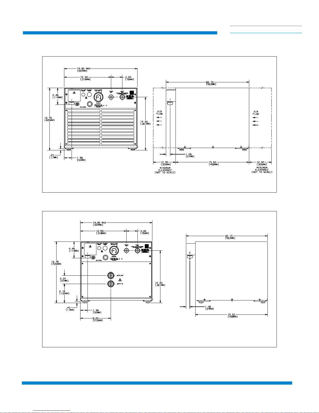
Figure 1-1: Air and Water Cooled 8200 Compressor Dimensions
1-2 P/N 8040353
Water Cooled
Page 7

8200 Compressor
-
C
TI CR
HELIX TECHNOLOGY CORPORATION
Y
OG
ENIC
S
1
3
2
Rear View - Air Cooled
6 7
5
4
8
9
10
11
12
Rear View - Water Cooled
13
14
15
16
Front View - Air and W ater Cooled
1. Compressor Input Power Block
2. Cold Head Power Receptacle
3. On-Board Power Receptacle
4. Helium Gas Fitting and Charge Valve
5. Helium Supply Pressure Gauge
6. Helium Gas Return Connector
7. Helium Gas Supply Connector
8. Rear Panel
9. Rear Grill
Figure 1-2: Component Locations
17
18
LEGEND
10. Cooling Water Output
11. Cooling Water Input
12. Rear Plate
13. 50/60 Hz Frequency Selector Switch
14. 208/220 Voltage Range Selector
Switch
15. Resettable Circuit Breakers
16. Compressor ON/OFF Switch
17. Front Panel
18. Front Grill
P/N 8040353 1-3
Page 8

Introduction
C
HELIX TECHNOLOGY CORPORATION
Table 1-1: Power Requirements (Steady-State Conditions)
-
TI CR
Y
OG
ENIC
S
Part Number Cooling Phase Hz
8032549G001 Air
Air
8032549G002 Air
Air
8032550G001 Water
Water
8032550G002 Water
Water
Table 1-2: General Sp ecification s
Specification Description
We ig ht 140 lbs (63.5 kg) approx im a te
3
3
1
1
3
3
1
1
50
60
50
60
50
60
50
60
Operating Voltage
Range
180-220
198-250
180-220
198-250
180-220
198-250
180-220
198-250
Nominal
Operating
Current
10A
10A
10A
10A
8.5A
8.5A
8.5A
8.5A
Weight
(shipping)
Power
consumption
Compressor input-power
cable
(customer-supplied)
Helium pressure Static: 245-255 psig (1688-1757 kPa) at 70 to 80°F (21 to
Ambient op er ating
temperature range
145 lbs (70.5 kg) approx im a te
2.0 kw, nominal operating(water), 2.1 kw nom inal operating
(air)
Recommended type SO-4 conduct or, 600V, neopre ne jacket
and 14-gauge wire.
Install per Figure C-1, El ec trical Schematic di agram, ensuring
compliance with all national, state and local sta ndards.
27°C)
Supply: nominal opera ti on: 270-290 psig (1860-200 0 kPa ) at
operating tempe ra ture.
50 to 100°F (10 to 38°C)
1-4 P/N 8040353
Page 9

8200 Compressor
Adsorber service schedule Replace ever y 12 m onths.
-
C
TI CR
HELIX TECHNOLOGY CORPORATION
Table 1-2: General Sp ecification s
Specification Description
Interface Cold head power receptacle: Mates with plug on cold head
power cable.
On-Board power re ce pt acle: Mates with plug on cold-he ad
power cable.
Compressor input-power terminal block enclosure: Mates with
input power cable, fabricated by customer or available from
CTI-CRYOGENICS.
Gas-supply connect or: 1/2-inch self-seali ng coupling
Gas-return connec to r: 1/ 2-i nch self-sealing coupl ing
Y
OG
ENIC
S
Cooling water requi re-
ments (water cooled only)
100°F (38°C) maxim um disc ha rge temp era ture
Refer to Figures 3-5 and 3-6 for parameters.
P/N 8040353 1-5
Page 10

8200 Compressor
Packaging of the S ystem
The Compressor
-
C
TI CR
HELIX TECHNOLOGY CORPORATION
Y
OG
ENIC
Section 2 - Inspection
A High-Vacuum Pump or Refrigerator System is packaged in separate
cartons for each maj or c omponent. An Instal la ti on, Op e ration, and
Servicing Manual i s inc lud ed in the carton for the com ponent packaged in
that carton.
On receipt, remove the 8200 Compre ssor from it s sh ip pin g carton and
inspect the compressor for evidence o f d amage as describ ed in this Section.
1. Unpack and remove the compressor from its shi ppi ng c art on.
S
2. Check the carton contents. It shou ld contain:
a. 8200 Compresso r (ai r cooled or water cooled).
b. Compressor Manua l P/N 8040353.
3. After unpacking, inspect the compressor for evidence of damage as
follows:
a. Inspect the compre ssor overall exterior for da ma ge .
b. Report damage to the shipp er a t on ce.
c. Retain shipping cart ons for st orage or return shipment.
When installing your system, CTI recomm en ds th at as you unpack a
component, you pe rform an inspection and the nec essary ta sks for syst em
installation for the component according to the manual included with the
component. Fina l system installation and operat ion will be performed
following proce dure s in t he hi gh-vacuum pump or re fri ge rator manual.
4. Check the helium pressure gauge. The gauge should indicate 250 psig
(1725 kPa) minimum at 70° F. If additional gas pressure is requ ired,
follow the instructions in Adding Helium Gas.
P/N 8040353 2-1
Page 11
8200 Compressor
Section 3 - Installation
Compressor Installation
Installation of your compressor requires no special tools other than those
supplied in the Installation and Scheduled Maintenance Tool Kit.
Preparing the Compressor Input-Pow er Cable
To supply input power to the 8200 compressor requires the fabrication of a
600-volt power cable that has an SO-4 conductor, 600-volt rating neoprene
jacket and 1 4-gauge or 2.3 mm
2
wire. Proceed as follows:
WARNING
-
C
TI CR
HELIX TECHNOLOGY CORPORATION
Y
OG
ENIC
S
Do not conne ct the compres s or to the power source at this time. All of
the preparation must be completed and all panels reinstalled before electrically connecting the compressor.
Unit must be wired by an authorized electrician in accordance with the
national Electri ca l Code, ANSI/NFPA 70-1987, as well as the local
codes. This shall include installation of a readily accessible disconnect
device into the fix ed wiring supplying power.
An insulated ear th ing cond uctor that is identica l in size, ins ulation material and thickness to the ea rth and unearth branch circuit supply conductors, except that it is green w ith or w i tho ut one or more yellow stripes is
to be installed as part of the branch circuit which supplies the unit or system. The earth ing conductor descri bed is to be connected to the earth at
the service equipm e nt, or supplied by a separatel y de rived system at the
supply transforme r or ge ne rator.
1. Prepare the input power cable by te rminating each of the four
conductors with a #10 ring terminal. Foll ow th e te rm inal
manufacturer’s instructions to insure proper crimping.
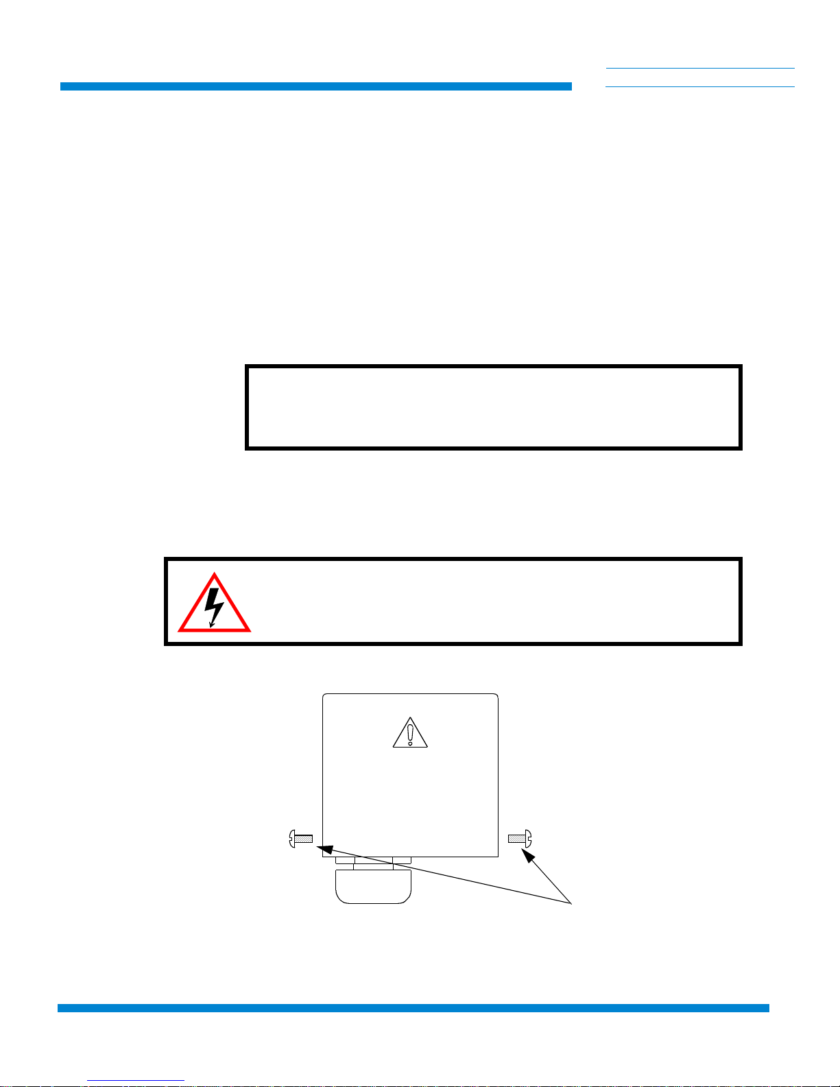
2. Disas s emble the elect r i cal terminal enc l o s ur e cover, mounted on
the compressor rear panel, as shown in Figure 3-1. Remove the two
screws securing the cover and lift it off.
3. If necessary, back off strain relief screws.
P/N 8040353 3-1
Page 12
Installation
-
C
TI CR
HELIX TECHNOLOGY CORPORATION
4. Thread input power cable end up through the strain relief i nto the
enclosure.
5. Attach the power conductors onto the appropriate terminals of the
termin al block.
a. For three-phase hookups, attach the three power leads to ter-
minals X, Y and Z.
b. For single-phase hookups, attach the two power leads to ter-
minals X and Y. DO NOT USE TERMINAL Z.
6. Tighten all terminals to 18-22 in.-lbs. torque.
7. Tighten down screws on strain relief.
Y
OG
CAUTION
Ensure that strain relief is tightened down on the outer insulation of the
input power cable and that the cable does not slide.
ENIC
S
8. Remount the te rm i n al enclosure cover and se cure with two screws .
9. Refer to Final Preparation of Compressor for correct phasing
checkout pr ocedure.
WARNING
Insure that the grou nd wire is returned to a suitable ground in a noninterrupting manner.
Figure 3-1: Electrical Terminal Enclosure with Cover in Place
3-2 P/N 8040353
Cover Scre ws
Page 13

8200 Compressor
-
C
TI CR
HELIX TECHNOLOGY CORPORATION
Y
(not used for single phase)
X
Ground Screw
Power Cable
Z
Y
OG
ENIC
S
Figure 3-2: Assembly of Conductors to Ter mi nal Block
Cooling Water Requirements (Water-Cooled Compressors Only)
If flexible water hose connections are used, install the barbed fittings
supplied with the compressor on the input and output connections:
1. Apply a light coating of st andard plumbing threa d sea la nt on
the barbed fitting threads .
2. Tighten fittings on 1/2-inch FPT input and 1/2-inch FPT output connections. DO NOT OVERTIGHTEN.
3. Connect flexibl e hoses to th e fi ttings and secure with hose clamps.
If har d pipin g is d esi red, inst all the wat er li nes direct ly on to t he co mpres sor
1/2-inch FPT input and output conne ctions. DO NOT OVERTIGHTEN.
CAUTION
Check water connections for leaks.
P/N 8040353 3-3
Page 14

Installation
Cooling Water: General Considerations
NOTE: Adjust your water flow to maintain an op tim um di scharge water
temperature of 85°F with a minimum input pressure of 2 psig. For detailed
water requirements, see below .
1. Cooling water must meet flow and pressure req ui rem ents as
indicated in the following subsections.
2. Cooling water having a pH value of 6.0 to 8.0 and a calcium - c arbonate concentration of less than 75 ppm, the quality of ty pic al
municipal drinking water, is acceptable. If th e cooling water has a
pH value lower than 6.0 or a calcium - carbonate conce ntration
higher than 75 ppm , wate r conditioning may be required.
3. To conserve water, the coolin g wat er should be shut off when the
compressor is not running.
CAUTION
-
C
TI CR
HELIX TECHNOLOGY CORPORATION
Y
OG
ENIC
S
If cooling water belo w 45° F (7° C) i s all ow e d to run through the
compressor while th e co mp re sso r is not ope ra ting, the compressor oil
will change viscosity and thicken, causing the co mpressor to overheat
and shut off at startup. In this event, repeatedly restart the compressor
and allow it to run unti l it ha s shu t off several time s. T he oil
temperature will rise and thereby allow continuous compressor
operation.
4. Drain and purge water from the compressor before shipping it back
to the factory or subject in g it to fre ez in g conditions. Purge water
from the compressor by blowi ng compressed air, regulated to 30 to
40 psig (200 to 275 kPa) into the compressor output connection and
allowing water to exit from the water in put conn ection.
Cooling Water: Flow and Pressure Requirements
CAUTION
If your water supply pressure falls below 2 psig due to back pressure,
the compressor wil l ov erheat and shut down.
Use the two graphs in Figure 3-3, to determine the minimum acceptable
cooling water sup ply p ressure at different flow rates a nd te m pe r at ure s .
3-4 P/N 8040353
Page 15

8200 Compressor
-
C
TI CR
HELIX TECHNOLOGY CORPORATION
Find the minimum pressure :
1. Determine the temperature variation of the cooling water.
Allow a ±10°F to th e pr esent water te mperature if a var iation
cannot be ascerta ine d. Plo t th e high and low temperat ures on
the verti cal axis o f th e lower graph.
The example describes cooling water that varies between 40°F and70°F.
2. Determine th e opt im um water flow rate by drawing a horiz ont al
line from the upper temperature variation figure on the lower graph
to the upp er curve of the a llowable op er ating range indicat ed by
cross-hatching. Draw a line from this intersecting point straight
down to the horizontal axis to find the optim a l fl ow rat e.
The example shows a solid arrow extending from 70°F and intersecting the
allowable operating range. Dashed arr ow s pointing downward indicate a
water flow rate of 0.5 gallons per minute.
Y
OG
ENIC
S
3. Determine the cooling water supply pressure drop by drawing a line
straight up from the flow rate in the lower graph to the upper graph.
At the point at whi ch t his l ine int e rsects the upper graph, d ra w a
line leftward to the verti ca l axi s and find the water supply pressure
drop.
The example shows dashed arrows extending from the lower to the upper
graph. On th e upper graph the dashed arrow s int ersect the gr aph curve at
approx imately 2.5 psig.
Figure 3-3: 8200 Compresso r Cooling Water Flow and Pressure Requirements
P/N 8040353 3-5
Page 16

Installation
Cooling Water: Temperature Ri s e
The temper ature o f the c oolin g water as it le aves th e compr essor s hould
not exceed 1 00° F.
Use the grap h in Figure 3-4 to determine the rise in cooling wat e r
temperatur e as it pa sses th r oug h th e co mpressor . Th is information is
provided for plant engineering pe rsonnel to determine cool in g w at e r
requirements.
Find the temperature rise:
1. Draw a vertic al line upward from the horizontal axis of the
graph at the water flo w rat e de te rm ined from the previous
section, until it hits th e graph curve.
CAUTION
-
C
TI CR
HELIX TECHNOLOGY CORPORATION
Y
OG
ENIC
S
The exampl e s ho w s dashed arrows po in ting upward to th e graph curve
from 0.50 gpm on the water flow rate axis.
2. At the point which the dashed arrows intersect the graph curve,
draw a straigh t line to the left to obtain the increase in output wate r
temperature.
The example sh ows a temperature increase of 20°F.
Figure 3-4: 82 00 C ompressor Water Discharge Te mperature Increase (°F)
3-6 P/N 8040353
Page 17

8200 Compressor
Final Preparation of Compressor
1. Using a voltmeter, measure the phase-to-phase voltage from the
power source. Compare this voltage to the following table and
position the voltage range selector s w itch to the “208V” or
“220V” position as requ ire d. A lso, set the fre quency selector
switch to the 50 Hz or 60 H z position, as appropriat e. S ee
Figure 1-2 for location of selector switches.
Table 3- 1: Voltage Specifications
-
C
TI CR
HELIX TECHNOLOGY CORPORATION
Y
OG
ENIC
S
Operating Voltage Range
60 Hz 50 Hz
198-212 180-212 208V
213-250 213-220 220V
2. Ensure that water is turned on fo r the w ater-coole d compressor.
3. Set the compressor ON/OFF switch (3) to OFF. Connect the inputpower cable to the power source Refer to Table 1-1, for electrical
power requirem ents.
4. Turn the compresso r switch to the ON posi ti on and allow the co m pressor to run for 15 minutes to stabilize the oil circuit. Make sure
that the compressor fan operates freely in the air-cooled comp r es sor.
5. Switch off the compre sso r and disconnect the inpu t-power cable.
6. Install the compressor in its permanent location on a level surfac e.
Air cooled units mu st have a mini mum cleara nce of 12 inch es at the
front and back for adequate airflow.
Voltage
Adjustment Swit ch
S1 Position
Connecting the Compressor to the Cold Head
Make the connecti ons between the cryop ump and compresso r. See Figure
3-5.
1. Remove dust plugs and caps from the supply fittings and return
lines, compressor, and cold head. Che ck all fitti ngs.
2. Connect the heli um-gas return line from th e gas-return connec tor
on the rear of the compressor to the gas-return connector on the
cold head.
P/N 8040353 3-7
Page 18

Installation
-
C
TI CR
HELIX TECHNOLOGY CORPORATION
3. Connect the heli um -ga s suppl y li ne fr om the ga s- supply connector
on the rear of the compressor to the gas-supply connector on the
cold head.
4. Attach the supply and return line identification decals (CTI-supplied) to their respectiv e c onnecting piping ends.
5. Verify prope r hel iu m suppl y sta tic pre ssure by c onfirming that the
helium pressure gaug e re ads 245-250 psig (1690-1 725 kPa), in an
ambient tempe ra ture range of 60 to 100°F (16 to 38°C).
Y
OG
WARNING
ENIC
S
!
Do not operate the 8200 Com pr essor un le ss a Cry opump or Waterpump
is connected to the system.
If the indicated pre ssure is higher than 250 psig (1725 kPa), reduce the
pressure as follows:
a. Remove the flare ca p from the gas charge fitting located on
the rear of the co m p ressor.
b. Open the gas charge valve very slowly. Allow a slight
amount of helium gas to escape until the helium pressure
gauge reads 250 psig (1725 kPa).
c. Close the gas charge valve an d reinstall the flare cap.
If the indicated pressure is lower than 245 psig (1690 kPa), add helium gas
as described in Adding Helium Gas.
6. Make the following electrical connections.
WARNING
The compressor ON/OFF power switch on the front of the compressor
must be in the OFF position before making any and all electrical connections.
a. Connect the cold head power cable to the rear panel of the
b. Connect the co mpressor input power cab le to t he power
c. Turn on compressor.
d. Your system is now ready for operation .
3-8 P/N 8040353
compressor and the other end to the electrical power connector on the hig h-va cuum pump cold head.
source.
Page 19

8200 Compressor
User’s
Vacuum
Chamber
-
C
TI CR
HELIX TECHNOLOGY CORPORATION
Y
OG
ENIC
S
Roughing Pump
Air Pressure (60-80 psi)
Nitrogen (40-80 psi)
On-Board
Cryopump
Helium Supply Line
Helium Return Line
On-Board Power Cable
Figure 3-5: Typical 8200 Compressor Installation
P/N 8040353 3-9
Page 20

8200 Compressor
Section 4 - Maintenance Procedures
Scheduled Maintenance
Removing the Compressor Adsorber
-
C
TI CR
HELIX TECHNOLOGY CORPORATION
Y
OG
WARNING
Always disconnect the compressor from all source s of el ectrical power
before performing any maintenance procedures.
The only scheduled maintenance re qui red on the 8200 Comp ressor is
replacement of the compressor adsorber (P/N 8080255K001) every 12
months.
ENIC
S
1. Shut down the compressor.
2. Disconnect the compressor input power cable from its electrical
power source .
3. Disconnect the flex lines from the gas-return and gas-supply connectors at the rear of the compress or.
4. Remove the screws hol ding the compressor rear grille, rear panel,
front panel and cover (Figure 1-2). Front and rear panels remain in
place.
5. Use the two wrenches (supplied) to avoid loosening the body of the
coupling from its adapter.
6. Unscrew the two self-sealing coupling ha lve s qui ckly to minimize
gas leakag e as sho w n in Figure 4-1.
7. Disconnect the adso rber-i n l et self-sealing coupling as shown in
Figur e 4-1.
8. Remove the bo lts, nuts, and washers that se cure the adsorber to the
base of the compressor. Save all nuts, bolts, and washers for installing the replacement adsorber.
9. Carefully lift the adsorber inward until the outlet self-sealing coupling clears the rea r panel and remove t he adsorber as shown in
Figur e 4-2.
10. Re m ove the adsorber from the com pre ssor as shown in Figure 4-2.
P/N 8040353 4-1
Page 21

Maintenance Proc edu res
Compressor
Rear
Panel
-
C
TI CR
HELIX TECHNOLOGY CORPORATION
Y
OG
ENIC
S
This 1 1/8 in. wrench
holds the coupling in
a stationary position.
To Disconnect The Coupling
Figure 4-1: Disconnecting/Connecting the Adsorber Self-Sealing Coupling
This 1 3/16 in. w rench is used
to loosen the self sealing
coupling connector. Note the
direction of the large arrow.
This 1 1/8 in. wrench
holds the coupling in
a stationary position.
To Connect The Coupling
This 1 3/16 i n. wrench is used
to tighten the self sealing
coupling connector. Note the
direction of the large arrow.
WARNING
Depres surize the ad s orber befo r e disposing of it. Att ach the depressurization fitting (inc l ude d in the Installation and Sch eduled Maintenance
Tool Kit) to the coup li ng half at either end of the adsorber and tight en it
slowly.
Figure 4-2: Removing the Adsor b er from the Compressor
4-2 P/N 8040353
Compressor Bas e
Page 22

8200 Compressor
Installing the Compressor Adsorber
1. Install the re placement ads orber as follow s :
a. Remove the dust caps from the self-sealing coupling halves
at each end of the replacement adsorber.
b. Write insta l lation date on th e ad s or b er decal.
c. Install the replacement adsorber following the steps for
compressor adsorber removal in reverse order. Use the hard-
ware saved in step 5 above .
2. Connect the ad so rbe r to the compressor intern al pipi ng. Refer to
Figur e 4-1.
a. Check the self-se aling connector flat rubbe r gasket to make
sure that it is clean and prope rly positioned.
CAUTION
-
C
TI CR
HELIX TECHNOLOGY CORPORATION
Y
OG
ENIC
S
Make sure to hold f as t on the lef t coupling n ut while tightening the
right coupling nut, as shown in Fi gure 4-1.
b. Make the first turns by hand and then firmly seal the con-
nection using th e two wrenches until the fit tings “bottom”.
Refer to Figure 4-1, for pr ope r coupling of the self-seal in g
connection
3. Replace the cove r and the front and rear grilles and secure them
4. Ensure that the pressure gauge reads 245-250 psig (169 0-1725
kPa). If additional gas pressure is required, follow th e in stru ctions
in, Adding Helium Gas.
5. Reconnect the re turn and supply flex lines to the com pre ssor.
6. Connect the compressor input power cable to the electrical power
source.
Unscheduled Maintenance
Suggested Unscheduled Maintenance Equipment
It is advisable to keep on hand the unscheduled mai nt enance equipment
and disposable suppli es liste d be lo w.
1. Helium, 99.999% pure .
2. Pressure regulator (0-3000/0-400 psig).
3. Maintenance manifold, P/N 8080250K003*.
P/N 8040353 4-3
Page 23

Maintenance Proc edu res
4. Helium charging line terminating in a 1/4-inch female flare fitting,
P/N 7021002P001.
5. Installation and Scheduled Maintenance Tool Kit, P/N
8032040G004.
*Available from stock ; consult the factory or your sales rep resentative.
Adding Helium Gas
Use only 99.999% pure he li um gas.
If the compressor he li um pressure gauge read s 0 , decontamination is
required. Refer to dec ont amination procedu res under, Helium Circuit
Decontamination, or contact the Produc t Se rvi ce D ep art m ent.
CAUTION
-
C
TI CR
HELIX TECHNOLOGY CORPORATION
Y
OG
ENIC
S
1. A User-supplied helium cha rging l ine te rm inating in a 1/4-inch
female flare fitting, and a two-stage pressure regulator rated at
0-3000/0-400 psig is required for this operation.
2. If you need to add heliu m mo re tha n once every several mo nth s ,
check for leaks ca use d by improperly connected self-sealing connection s o r any mechanical joint within th e compres s or.
There are two conditions that r equ ire the addition of he lium gas:
1. Compressor not operat ing; helium pressure gauge rea ds 245
psig or below.
2. Compressor operati ng; helium pressure reads 270 psig , or bel ow.
To add helium gas:
1. Attach a pressure re gulator (0-3000/0-4 00 psig) and charging
line to a helium gas (99.999% pure) bottle. DO NOT OPEN
THE BOTTL E AT THIS TIME. Purge the regulator and
charging lines as instructed in steps a through e below. Do not
use helium gas that is less than 99.999% pure.
a. Open the regulator a smal l amo unt by turning th e ad justing
knob clockwi s e unt il it contacts the dia phragm, then turn
approx imately 1 /8 to 1/4 tur n more, so th at the regulator is
barely open .
b. Slowly open the bottle valve, and purge the regulator for 10
4-4 P/N 8040353
to 15 seconds. Turn the regulat or knob countercloc kwise
until the helium stop s flowing.
Page 24

8200 Compressor
-
C
TI CR
HELIX TECHNOLOGY CORPORATION
c. Connect the charge line to the helium pre ssure regulator.
d. Remove the flare cap of the gas charge fitting on the rear of
the compressor. Loosely conn ec t th e charge line to the
charge fitting.
e. Set the helium pressure regulator to 10 to 25 psig (70- 125
kPa). Allow helium gas to flow t hrough the charging line
and around the loosened flare fitting for 30 seconds to purge
the charging line of air. Then tighten the flare nut at the end
of the charge line.
(This procedur e is required to ensure that bot h th e regulator and the
charging line w ill be purged of ai r and that the air trapped in the regulator
will not dif fus e back into the he liu m bottle . For best re sults, CT I sugg ests a
dedicated heli um bottle, regulator, and line, which are never separat ed, for
adding helium. )
2. Set the helium pressure regulator to 300 psig (2070 kPa). Depending on the compressor ope rating state, add heliu m gas:
Y
OG
ENIC
S
a. If the compressor is run ning (approximatel y 2 hours operat-
ing time) under norm a l ope ra ting conditions, slowly ope n
the helium ch arge va lve on the rear of the com pressor.
When the helium pre ssure gauge rises to 270 - 290 psig
(1860 - 2000 kPa) tightly close the ch arge va lve.
b. If the compressor is not running, slowly open the heli um
charge valve. When the helium pressure gauge rises to 245 255 psig (1688 - 1757 kPa), tightly clos e th e charge valve.
Add helium gas slowly to prevent relief valve blow-off.
3. Ensure that the helium char ge valve on the co mp re ssor is tightly
closed . S hut off the helium pr essure regulato r on t he helium bo ttle
and remove the cha rging line f rom the m al e fl are fit ti ng. Shut off
the heli um gas bottle valve . Reinstall the flare cap.
Helium Circuit Decontamination
Refer to Section 4 - Maintenance of the appropriate On-Board Cryopump
Installat ion Oper atio n, an d Main tena nce ma nua l for in fo rmat ion on helium
circuit decontaminat ion.
CAUTION
P/N 8040353 4-5
Page 25

-
C
Appendix A - Customer Support Information
TI CR
HELIX TECHNOLOGY CORPORATION
Appendix A - Customer Support Information
Introduction
Refer to Table A-1 for the nearest Customer Support Center for technical
assistance or service for CTI-CRYOGENICS products. North American
customers may call 800-FOR-GUTS (800-367-4887) 24 hours a day, seven
days a week. All other cu stom e rs mu st c al l their local Customer Supp ort
Center.
NOTE: Please contact the Customer Suppo rt Cent er in Mansf ie ld ,
Massachusetts in the Uni te d States of America by dialing 508-337-5599 if
a Customer Support office is not located in your area.
Please have the following information available when calling so that we
may assist you:
Y
OG
ENIC
S
• Product Part Number
• Product Serial Number
• Product Application
• Specifi c P roblem Area
• Hours of Operation
• Equipmen t Type
• Vacuum Syst em Brand/Model/Date of Manu fac t ure
For your convenience, you may also e-mai l us a t:
contact@helixtechnology.com
Visit us at our corporate website:
www.helixtechnology.com
A-1
Page 26

Appendix A - Customer Support Information
Table A-1: CTI-CRYOGENICS Product Customer Support Centers
-
C
TI CR
HELIX TECHNOLOGY CORPORATION
Y
OG
ENIC
S
United States and Canada
Guaranteed Uptime Support Line GUTS
Dial: 800-FOR-GUTS (800-367-4887) (within USA)
508-337-5599 (outside USA)
24 hours a day, seven days a week
Corporate Headquarters: 800-379-7224 (within USA)
508-337-5000 (outside USA)
Austin, TX: 800-324-6445 (within USA)
512-912-2800 (outside USA)
Longmont, CO: 800-776-6543 (within USA)
303-652-4400 (outside USA)
Santa Clara, CA: 800-324-6449 (within USA)
408-562-5940 (outside USA)
France, Spain, Po rtugal , Gr eece , Belgi um, North
Africa
Dial: +(33) 1-6935-2600
24 hours a day, seven days a week
®
Germany, Italy, Denmark, Switzerland, Holland,
Norway, The Netherlands
Dial: +(49) 6151-959-55
24 hours a day, seven days a week
United Kingdom, Ireland, N. Ireland, Scandinavia
Dial: +(44) 1-506-460017
24 hours a day, seven days a week
A-2
Japan
Dial: +(81) 0120-60-4887
24 hours a day, seven days a week
Taiwan
Dial: +(886) (3) 516-9022
24 hours a day, seven days a week
Austr alia, Ne w Zealand, Tasmania
Dial: +(612) 9-4810748
24 hours a day, seven days a week
India
Dial: +(91) 22-7632906
24 hours a day, seven days a week
Korea
Dial: +(82) 2-577-3181
24 hours a day, seven days a week
China
Dial +(86) 21-6279-1389
24 hours a day, seven days a week
Singapore, Malaysia, Philippines, Indonesia
Dial: +(65) 268-20 24
24 hours a day, seven days a week
Israel
Dial: +(972) 3-9247710
24 hours a day, seven days a week
Page 27

8200 Compressor
Appendix B - Troubleshooting Procedures
-
C
TI CR
HELIX TECHNOLOGY CORPORATION
WARNING
Disconnect the compressor before performing any troubleshooting procedures.
The compressor pump is hot after operating. Wait for the pump to cool
down before working on the inside of the compressor
Table B-1: Compressor Troubleshooting Procedur es
Problem Possi ble Cause Correc t ive Action
Y
OG
ENIC
S
1) System power ON/
OFF switch (CB1) and
compressor switch (S1)
remain s in the ON posi tion when switched on
but the compressor w ill
not run. Refer to Figure
C-1 for id entification of
all electrical components
2) System power ON/
OFF switch (CB1)
remain s in the ON posi tion, but the compressor
will not run.
1) The thermal prote ct ive
switch (TS1) is closed, activating the relay-trip coil in the ON/
OFF switch (SW1).
2) Incorrect phasing at input
power.
3) Excessive current drain has
activated the series trip in the
compressor ON/OFF switch.
1) No power coming from the
power source.
2) Incorrect or disconnected
wiring within the compressor
1) T est switch (TS1) on air-cooled
compressor; test (TS1) and (T S2)
on water-cooled com pre ssor. If
continuity is foun d in any sw i tch,
contact the Product Service
Department.
2) Correc t phase sequence at
input power cable.
3) Measure and record the current
and contac t th e Product Servi ce
Department.
1) Check service fuse s, circui t
breakers , an d w iring associated
with power sour ce , a nd re pair as
needed.
2) Check the compressor against
its electrical schematic, Figure
C-1.
P/N 8040353 B-1
Page 28

Appendix B - Troubleshooting Procedures
Table B-1: Compressor Troubleshooting Procedur es
Problem Possi ble Cause Correc t ive Action
-
C
TI CR
HELIX TECHNOLOGY CORPORATION
Y
OG
ENIC
S
3) Compressor stops
after sev eral minu tes of
operation and remains
off.
1) High tempera tur e of the
compressor is caused by insufficient co ol ing water, resulting
in the opening of thermal protective switch (water -cooled
compressor only).
2) After turn-off, very cold
cooling water was left running
through the compressor. The
resulting low oil tem pe r atu r e
has caused a restriction of oil
flow through the metering orifice during startup.
3) Very cold cooling water is
circulating through the compressor. The resulting low oil
temperat ure cause s a re st ri ct ion
of oil flow through the metering
orifice during startup.
1) Confirm that cooling water to
the compressor is flowing. Confirm that proper cooling water
flow rate and pressure exist by
referring to Figure 3-3.
2) Turn on the comp re s s o r and
allow it to run until it has stopped
several times, allowing the oil
temper ature to rise and the compressor to operate continuously
for one hour minimum.
3) Rechec k for proper cooling
water temperature per, Cooling
Water Requirements (WaterCooled Compressors Only).
4) Ambient temperature is
unusually high resultin g in the
opening of the th ermal protective switch (air-c ooled compressor only).
5) Insufficient helium supply
pressure is indicated by the supply pressure gauge.
6) High tempera tur e of the
compressed heliu m in the discharge line from the compres sor pump has tripped the
thermal prot ec ti ve switc h.
7) Mechan ical seizur e.
4) Provide a free flow of air to the
compressor. Confirm a 12-inch
(30 cm) clearance at the front and
back of the compressor. Confirm
unobstr ucted and clean heat
exchanger surfaces.
5) Add helium pe r, Unscheduled
Maintenance.
6) Confirm that oil is visible in
the compressor sight glass (aircompressor only).
7) Contact the Product Service
Department.
B-2 P/N 8040353
Page 29

8200 Compressor
-
C
TI CR
HELIX TECHNOLOGY CORPORATION
Table B-1: Compressor Troubleshooting Procedur es
Problem Possi ble Cause Correc t ive Action
Y
OG
ENIC
S
4) Compressor pump
stops after several minutes of operating and
then switch es O N and
OFF at short intervals.
5) Compressor operates
but cold head motor does
not run.
1) Intermittent powe r so urc e
voltage.
1) Loose or defect ive ca ble. 1) Check cold head cable.
1) Confirm power source voltage
between 198-2 50V, 60 Hz or 180220V, 50 Hz an d re store if necessary.
P/N 8040353 B-3
Page 30

8200 Compressor
Appendix C - Electrical Schematics for 8200
Compressor
-
C
TI CR
HELIX TECHNOLOGY CORPORATION
Y
OG
ENIC
S
P/N 8040353 C-1
Page 31

GRN/Y E L 1 4
M2
FAN
AIR COOLED ONLY
P5
1
3
4
0
P2
4
0
1
3
J5
J2
M1
S
R
123
444
444
123
TS2
PUMP
C
WATER C OOLED ON LY
SOL1
TS1
4
0
1
2
123
P3
0
1
2
2 2
1 1
4
J3
3
P4
2 2
3
123
1 1
J4
ON-BOARD CONNECT OR
ABCDEFGHJ
J10
123456789
123456789
J1 P1
K
10 10
44444
J11
ABCDE
ORN
VIO GRA
YEL
GRN/YEL
CRYO-TORR
0
F
YELYEL
CR1
BRN-14 BRN 14
RED
BLK
1 2 5
35UF
C1
R2
119UF
C2
K1
NONC
WHT/BL K
GRN/ YEL-14
POWER IN
Z
L3
x Y GND
L1 L2
208/230 VAC 3ph
TB1
R1
15A15A 1A
1 2 3
P1 P2 P3
CB1
SRT
PM
NO C NC
A BC
ETM
WHT/ORN
7 765 5
J/P7
WHT
WHT/RED
t
12
24
T1
188
217
WHT
C
BLK 14 BLK 14
WHT/RED
RED 14 RED 14
WHT/RED
CB3
CB2
250
WHT/BR N
WHT/OR N
66
4
5 5
J/P6
BRN BRN
WHT/BRN
8
4
3A
12
3A
RED
W/BRN
BRN
GRA
WHT/BLK/VIO
1
2
S2
50 HZ
60 HZ
2a
2b
W/BLK
WHT/BLK/VIO
ORN WHT/RED
7
7654321 1
BLK
20
t
GRA
0
10
ORN
WHT/BLK/BLU
J/P8
WHT WHT/BRN YEL
24
T2
J/P9
ORN
1
5
9
44
3 3221 1
W/YEL
W/VIO
WHT
0 WHTWHT
t
162
212
0
108
125
BLU BLK BLK
WHT/BL U
WHT/GR A
33
11
2 2
VIO
WHT/BLU
3
7
11
BLU
RT1
YEL
2
1
S1
1a
1b
2a
2b
220V
208V
19.9 - 23.5
20.5 - 21.2
21.9 - 23.5
CONTROL V OLTS
W/ORN
2
3
5
6
WHT/RE D WHT/VI O
WHT/VI O
WHT/YE L YEL
BLK
GRA
0 WHT BR N
162
212
t
t
12
217
250
188
BRN
WHT/BR N
WHT/OR N
6
55
3211
4 4
K2
WHT/O RN
13
14
0
20
0
108
125
WHT/BL U
BLU
WHT/GR A
WHT
WHT/YE L
CH VOLTS
118 - 139
208V 50 Hz
180 - 212
FREQUE NCY LINE VOLT S S1 S2
1. VOLTAGE SELECTION:
NOTES:
20.5 - 24.0
121 - 125
148 - 159
138 - 162
60 Hz
208V 60 Hz
213 - 220 220V 50 Hz
198 - 212
213 - 250 220V
50 Hz
60 Hz
Figure C-1: 8200 Comp ressor E lectr ical Schematic P/N 803 2563P001 Rev. 100
119UFSTART CAPA CITOR,
35UF
RUN CAPACI TOR,
MAIN CIRCUIT BREAKER
CB1 C1C2
CB2 CIRCUIT BREAKER, 3A
CB3 CIRCUIT BREAKER, 3A
CR1 MOTOR S TA RT RELAY
ETM METER ELAPS E D TIME
J1 COLDHEAD CONNECT OR
J2 PUMP CONNECTOR
TRANSFORMER CONNECTO R
TRANSFORMER CONNECTO R
J3 THERMOSTAT CONNECT OR
J4 SOLENOID CONNECTOR
J5 FAN CONN ECTOR
J/P6 TRANSFOR MER CONNECTOR
J/P7 TRANSFOR MER CONNECTOR
J/P8
J/P9
K1 OVERTE MPERATURE TRIP R ELAY
K2 VOLT AGE S EL ECTOR RELAY
M1 PUMP MOTO R
M2 FAN MOT OR, AI R COOL ED ONLY
PM PHASE MONI TOR
J10 ON-BOARD CONN ECT OR
J11 CRYO-TORR CONN ECTO R
R1 OVER TEMPERATURE RES ISTOR
R2 BL EED RESISTOR
RT1 CURRENT L IMITER
S1 VOL TAGE SEL ECTOR SWI TCH
S2 FR EQUENC Y SELECT OR SWIT CH
TRANSFORMER
SOL1 SOLENOIDT1T2
TRANSFORMER
TERMINAL BLOCK, INCOMING VOLTAGE
THERMOSTAT
THERMOSTAT, FOR WATER COOLED
USE TS1 AND TS2
TB1
TS1
TS2
Page 32

Figure C-2: 8200 Comp ressor Ele ctr ical Schematic P/N 803 2564P001 Rev. D
Page 33

8200 Compressor
Appendix D - Components in the Electrical
Control Mo dule of the 8200 Compr e ssor
-
C
TI CR
HELIX TECHNOLOGY CORPORATION
Y
OG
ENIC
S
1. Overtemperature Resistor R1
2. Run Capacitor, 35 µf C1
3. Start Capacitor, 119 µf C2
4. Transformer T2
5. Phase Monitor PM
6. Voltage Selector Relay K2
7. Main Circuit Breaker CB1
8. Circuit Breaker, 3A CB2
Figure D-1: Components in th e El ectrical Control Chassis of the 8200 Compressor
P/N 8040353 D-1
9. Circuit Breaker, 3A CB3
10.Voltage Selector Switch S1
11.Frequency Selector Switch S2
12.Overtemper ature Trip Relay K1
13.Transformer T1
14.Motor Start Relay CR1
15.Meter, Elapsed Time ETM
Three-Phase Scott-T Configuration
Page 34

Appendix D - Components in the Electrical Control Module of the 8200 Compressor
-
C
TI CR
HELIX TECHNOLOGY CORPORATION
Y
OG
ENIC
S
1. Coldhead Phase-Shifting ResistorR3
2. Overtemperature Resistor R1
3. Run Capacitor, 35 µf C1
4. Start Capacitor, 119 µf C2
5. Transformer T2
6. Run Capacitor, 2 µf C4
7. Run Capacitor, 6 µf C3
8. Main Circuit Breaker CB1
Figure D-2: Components in the Electrical Control Chassis of the 8200 Compressor - Single-
D-2 P/N 8040353
9. Circuit Breaker, 3A CB2
10.Circuit Breaker , 3A CB3
11 . Voltage Selector Switch S1
12.Frequency Selector Switch S2
13.Relay, Trip Relay K1
14.Transformer T1
15.Motor Start Relay CR1
16.Meter, Elapsed Time ETM
Phase RC Configuration
Page 35

8200 Compressor
Appendix E - Flow Diagrams for 8200
Air- Cooled and Water- Cooled Compressors
Compressor Gas and Oil Flows
Refer for Figure E-1 or Figu re E -2 whi le reviewing this subsection.
Helium return in g fro m th e co ld hea d en te rs th e compressor, and a small
quantity of oil is injec ted into the gas stream, thereby overcoming helium
low specific head and inability to carry heat produced during compression.
Helium is then compresse d and passed th r oug h a heat exchanger for
removal of compression -c aused heat. The helium flows t hrough a bulk oil
separator, oil-mist separator, and helium filter cartridge, where oil and
contamin ants are removed.
-
C
TI CR
HELIX TECHNOLOGY CORPORATION
Y
OG
ENIC
S
A differential pressure relief valve in the compressor limits the operating
pressure differential betw een the helium supply an d return lines, thereby
allowing compressor operating without cold head operation. When cold
head operation reaches a steady-state condition, further pressure regulation
is unnecessary.
P/N 8040353 E-1
Page 36

Appendix E - Flow Diagrams for 8200 Air-Cooled and Water-Cooled Compressors
-
C
TI CR
HELIX TECHNOLOGY CORPORATION
Y
OG
ENIC
S
Figure E-1: Flow Diagram of the 8200 (Air-Cooled) Compressor
E-2 P/N 8040353
Page 37

8200 Compressor
-
C
TI CR
HELIX TECHNOLOGY CORPORATION
Y
OG
ENIC
S
Figure E-2: Flow Diagra m of the 8200 (Water-Cooled) Comp ressor
P/N 8040353 E-3
 Loading...