

Helios VDD T120, VDD 355, VDD 400, VDD 450, VDD 500 Installation And Operating Instructions Manual
...
Helios Ventilatoren
MONTAGE- UND BETRIEBSVORSCHRIFT
DE
INSTALLATION AND OPERATING INSTRUCTIONS
NOTICE DE MONTAGE ET D’UTILISATION
EN
FR
Dachventilatoren
Roof Fans
Tourelles de toitures
VDD.. T120
Baureihen
Series Ø 315-710 mm
Séries

DEUTSCH
Inhaltsverzeichnis
KAPITEL 1 SICHERHEIT .................................................................... Seite 1
1.0 Wichtige Informationen .................................................................. Seite 1
1.1 Warnhinweise ......................................................................... Seite 1
1.2 Sicherheitshinweise ..................................................................... Seite 1
1.3 Einsatzbereich ......................................................................... Seite 2
1.4 Grenzen ............................................................................. Seite 2
1.5 Berührungsschutz ...................................................................... Seite 2
1.6 Personalqualifikation .................................................................... Seite 3
1.7 Förder- und Drehrichtung ................................................................ Seite 3
1.8 Drehzahlsteuerung ..................................................................... Seite 3
1.9 Motorschutzeinrichtung .................................................................. Seite 3
1.10 Funktionssicherheit – Notbetrieb ........................................................... Seite 3
KAPITEL 2 ALLGEMEINE HINWEISE ......................................................... Seite 3
2.0 Garantieansprüche – Haftungsausschluss .................................................... Seite 3
2.1 Vorschriften – Richtlinien ................................................................. Seite 3
2.2 Transport ............................................................................ Seite 3
2.3 Sendungsannahme ..................................................................... Seite 3
2.4 Einlagerung ........................................................................... Seite 4
2.5 Serienausführung ...................................................................... Seite 4
2.6 Leistungsdaten ........................................................................ Seite 4
2.7 Geräuschangaben ...................................................................... Seite 4
KAPITEL 3 MONTAGE ..................................................................... Seite 4
3.0 Aufstellung ........................................................................... Seite 4
3.1 Befestigung ........................................................................... Seite 4
3.2 Abmessungen ......................................................................... Seite 5
3.3 Elektrischer Anschluss .................................................................. Seite 5
3.4 Inbetriebnahme ........................................................................ Seite 5
3.5 Betrieb .............................................................................. Seite 6
KAPITEL 4 INSTANDHALTUNG UND WARTUNG ................................................ Seite 6
4.0 Instandhaltung und Wartung .............................................................. Seite 6
4.1 Reinigung ............................................................................ Seite 6
4.2 Hinweise – Störungsursachen ............................................................. Seite 6
4.3 Ersatzteile ............................................................................ Seite 7
4.4 Stilllegen und Entsorgen ................................................................. Seite 7
KAPITEL 5 TECHNISCHE DATEN ............................................................ Seite 8
5.0 Technische Daten ...................................................................... Seite 8
KAPITEL 6 SCHALTPLAN-ÜBERSICHT ........................................................ Seite 8
6.0 Schaltpläne ........................................................................... Seite 8
Erreichen der Lebensdauer, Entsorgung
Bauteile und Komponenten des Ventilators, die ihre Lebensdauer erreicht haben, z.B. durch Verschleiß, Korrosion, mechanische Belastung, Ermüdung und / oder
durch andere, nicht unmittelbar erkennbare Einwirkungen, sind nach erfolgter Demontage entsprechend den nationalen und internationalen Gesetzen und Vorschriften
fach- und sachgerecht zu entsorgen. Das Gleiche gilt auch für im Einsatz befindliche Hilfsstoffe wie Öle und Fette oder sonstige Stoffe.
Die bewusste oder unbewusste Weiterverwendung verbrauchter Bauteile wie z.B. Laufräder, Wälzlager, Keilriemen, etc. kann zu einer Gefährdung von Personen, der
Umwelt sowie von Maschinen und Anlagen führen. Die entsprechenden, vor Ort geltenden Betreibervorschriften sind zu beachten und anzuwenden.

Montage- und Betriebsvorschrift
KAPITEL 1
SICHERHEIT
1.0 Wichtige Informationen
VDD.. – Dachventilatoren
DE
Zur Sicherstellung einer einwandfreien Funktion und zur eigenen Sicherheit sind alle nachstehenden Vorschriften genau
durchzulesen und zu beachten.
Dieses Dokument ist Teil des Produktes und als solches zugänglich und dauerhaft aufzubewahren. Der Betreiber ist
für die Einhaltung aller anlagenbezogenen Sicherheitsvorschriften verantwortlich.
m
m
m
GEFAHR
WARNUNG
VORSICHT
1.1 Warnhinweise
Nebenstehende Symbole sind sicherheitstechnische Warnhinweise. Zur
Vermeidung von Gefahrensituationen müssen alle Sicherheitsvorschriften
bzw. Symbole unbedingt beachtet werden!
1.2 Sicherheitshinweise
Schutzbrille
l
Dient zum Schutz vor Augenverletzungen.
Gehörschutz
p
Dient zum Schutz vor allen Arten von Lärm.
Arbeitschutzkleidung
r
Dient vorwiegend zum Schutz vor der Erfassung durch bewegliche Teile.
Keine Ringe, Ketten oder sonstigen Schmuck tragen.
Schutzhandschuhe
n
Schutzhandschuhe dienen zum Schutz der Hände vor Reibung, Abschürfungen,
Einstichen oder tieferen Verletzungen sowie vor Berührung mit heißen
Oberflächen.
Sicherheitsschuhe
m
Sicherheitsschuhe dienen zum Schutz vor schweren herabfallenden Teilen
und verhindern das Ausrutschen auf rutschigem Untergrund.
Haarnetz
Das Haarnetz dient vorwiegend zum Schutz vor der Erfassung von langen
Haaren durch bewegliche Teile.
Für Einsatz, Anschluss und Betrieb gelten besondere Bestimmungen; bei
Zweifel ist Rückfrage erforderlich. Weitere Informationen sind den einschlägigen
Normen und Gesetzestexten zu entnehmen.
m
schutz- und Unfallverhütungsvorschriften einzuhalten!
Bei allen Arbeiten am Ventilator sind die allgemein gültigen Arbeits-
• Ventilator nicht an Anschlussleitungen, Klemmenkasten oder Laufrad trans-
portieren! Nicht unter der schwebenden Last aufhalten!
• Alle elektrischen Arbeiten sowie die Inbetriebnahme dürfen nur von autorisier-
tem Elektrofachpersonal durchgeführt werden! Installations-, Instandhaltungsund Wartungsarbeiten dürfen nur von geeignetem Fachpersonal durchgeführt werden!
• Vor allen Reinigungs-, Installations-, Instandhaltungs- und Wartungsarbeiten
oder vor Öffnen des Anschlussraums ist folgendes einzuhalten:
- Das Gerät ist allpolig vom Netz zu trennen!
- Der Stillstand rotierender Teile ist abzuwarten!
- Das Gerät ist gegen Wiedereinschalten zu sichern!
• Dachventilatoren nur mit für das Gewicht geeigneten Transportmitteln bewe-
gen, beim Transport Sicherheitsschuhe tragen!
• Beim Auspacken des Gerätes Handschuhe/Sicherheitsschuhe tragen.
1

Montage- und Betriebsvorschrift
VDD.. – Dachventilatoren
• Geeignete Tragkraft, -eigenschaften des Befestigungsuntergrunds sicher-
stellen und diesbezüblich geeignete Befestigungsmittel verwenden.
• Bei Arbeiten oder Aufenthalt in der Nähe des laufenden Ventilators kann je
nach Ventilatorgröße ein Gehörschutz erforderlich sein!
• Alle anlagenbezogenen Sicherheitsvorschriften sind einzuhalten! Gegebenen-
falls müssen weitere länderspezifische Vorschriften eingehalten werden!
• Der Berührungsschutz gemäß DIN EN 13857 ist im eingebauten Zustand
sicherzustellen (Kapitel 1.5)! Kontakt mit rotierenden Teilen muss verhindert
werden.
• Es ist sicherzustellen, dass sich im Ansaugbereich keine Personen, Textilien
oder andere ansaugbare Stoffe, wie z.B. auch Kleidung von Personen,
befinden. Weiterhin muss der Ausblasbereich frei von Gegenständen und
Stoffen sein, die weggeschleudert werden können.
• Eine leichte Zugänglichkeit für Inspektions- und Reinigungspersonal ist zu
gewährleisten, andere Personen dürfen keinen Zugang zum Ventilator haben!
• Eine gleichmäßige Zuströmung und ein freier Ausblas sind zu gewährleisten!
• Ein Motorschutzgerät (Zubehör) für alle Motoren ist zwingend erforderlich
(ausgenommen Ø 315, 355 und 400/6)!
* Die maximale Fördermitteltemperatur des
jeweiligen Gerätes ist den aktuell gültigen
Helios Verkaufsunterlagen zu entnehmen.
m
WARNUNG
1.3 Einsatzbereiche
– Bestimmungsgemäßer Einsatz:
Förderung normaler oder leicht staubhaltiger (Partikelgröße < 10 µm), wenig aggressiver und feuchter Luft, in
gemäßigtem Klima bei Temperaturen im Bereich von -20 °C bis max +120 °C, bei stationärem Einbau des Ventilators.
Aufstellung: Auf Dächern waagrecht (Kapitel 3.0), unzugänglich für nicht autorisierte Personen.
– Vernünftigerweise vorhersehbarer Fehlgebrauch:
Die Ventilatoren sind nicht zum Betrieb unter erschwerten Bedingungen wie z.B. aggressive Medien, längere
Stillstandzeiten, starke Verschmutzung, übermäßige Beanspruchung durch klimatische, technische oder elektronische Einflüsse geeignet. Eine Verwendung in einer mobilen Einheit (z.B. Fahrzeuge, Flugzeuge, Schiffe, usw.) ist nicht
vorgesehen. Die Motorbemessung erfolgte für Dauerbetrieb gemäß S1 und schließt hohe Schalthäufigkeit aus. Es ist
sicherzustellen, dass der vorgegebene Einsatz bereich eingehalten wird.
– Missbräuchlicher, untersagter Einsatz:
Förderung von explosionsfähigen Gasgemischen/Medien. Aufstellung in einem/r explosionsgefährdeten Bereich/
Atmosphäre. Betrieb ohne normgerechte Schutzeinrichtungen (z.B. Schutzgitter). Förderung von Feststoffen
oder Feststoffanteilen > 10 µm im Fördermedium sowie Flüssigkeiten. Förderung von abrasiven und/oder die
Ventilatorwerkstoffe angreifende Medien. Senkrechte (hängend) Aufstellung des Dachventilators.
1.4 Grenzen
Räumlich:
Für den Ansaugbereich ist eine gerade, glatte Rohrstrecke oder ein freies Ansaugen vorzusehen. Der Ausblasbereich
darf nicht versperrt werden, es ist ein Mindestabstand von 1 m zum Ventilator einzuhalten. Der Ventilator muss für
Reinigungs- und Wartungszwecke leicht zugänglich sein, insbesondere der Klemmenkasten/Revisionsschalter.
Schnittstelle Energieversorgung:
– Anschluss nur mit festverlegten Leitungen
– 3 Phasen + PE + 2x TB (TK) bzw. TP (KL)
– ein Motorvollschutzgerät ist für alle Geräte zwingend erforderlich (ausgenommen Ø 315, 355 und 400/6)!
1.5 Berührungsschutz
Beim Einbau sind die allgemein gültigen Arbeitsschutz- und Unfallverhütungsvorschriften einzuhalten!
Der Betreiber ist für die Einhaltung verantwortlich!
– Kontakt mit rotierenden Teilen muss verhindert werden. Es ist sicherzustellen, dass sich im Ansaugbereich keine
Personen, Textilien oder andere ansaugbare Stoffe, wie z.B. auch Kleidung von Personen, befinden.
– In Abhängigkeit der Einbauverhältnisse kann ein Berührungsschutz saugseitig erforderlich sein.
– Ventilatoren, die durch ihre Einbauweise (z.B. Anschluss an Lüftungskanäle) geschützt sind, benötigen kein
Schutzgitter, wenn die Anlage die gleiche Sicherheit bietet. Es wird darauf hingewiesen, dass der Betreiber für
Nichteinhaltung der aktuellen Norm (DIN EN 13857) und für Unfälle infolge fehlender Schutzeinrichtungen haftbar
gemacht werden kann.
1.6 Personalqualifikation
– Alle elektrischen Arbeiten sowie die Inbetriebnahme dürfen nur von Elektrofachkräften ausgeführt werden.
– Installation, Wartung und Instandhaltung mit Ausnahme der elektrischen Arbeiten dürfen nur von Fachkräften
(Bsp.: Industriemechaniker, Mechatroniker, Schlosser oder vergleichbar) ausgeführt werden.
2
Montage- und Betriebsvorschrift
1.7 Förder- und Drehrichtung
VDD.. – Dachventilatoren
DE
m
m
m
m
* Die zugehörigen Steuergeräte sind den
aktuell gültigen Helios Verkaufsunterlagen
zu entnehmen.
m
* Die zugehörigen Motorschutzeinrichtungen
sind den aktuell gültigen Helios Verkaufsunterlagen zu entnehmen.
WARNUNG
n
l
WARNUNG
ACHTUNG
ACHTUNG
ACHTUNG
m WARNUNG
Durch vom Ventilator herausgeschleuderte Teile können Ihre Augen verletzt werden!
Zur Drehrichtungskontrolle Schutzbrille tragen!
m WARNUNG
Das drehende Laufrad kann Ihre Finger/Arme abtrennen oder einziehen!
Betrieb nur mit montierten Sicherheitseinrichtungen!
Keine Gegenstände in das rotierende Laufrad stecken! Beschädigungsgefahr!
Die Dachventilatoren haben eine feste Motor-Drehrichtung, die auf den Geräten durch einen Pfeil gekennzeichnet ist
(kein Reversierbetrieb möglich). Die falsche Drehrichtung kann zur Überhitzung und Zerstörung des Ventilators führen!
Die Drehrichtung darf nur nach Abschalten während dem Austrudeln des Ventilators geprüft werden!
1.8 Drehzahlsteuerung*
Alle Ventilatoren vom Typ..D können auf eine der nachfolgenden Weisen drehzahlgesteuert werden.
a) Transformator: Alle Ventilatoren bis Ø 450 sind über einen Transformator spannungssteuerbar.
b) Frequenzumrichter: Alle Ventilatoren ab Ø 500 sind über einen Frequenzumrichter mit Sinusfilter drehzahlsteuerbar.
Die Verwendung eines Frequenzumrichters ohne Sinusfilter ist nur mit Einsatzfreigabe seitens Helios möglich.
Der Einsatz von Fremdfabrikaten kann vor allem bei elektronischen Geräten zu Funktionsproblemen,
Zerstörung des Reglers und/oder des Ventilators führen. Bei Einsatz seitens Helios nicht freigegebener
Regelgeräte, entfallen Garantie- und Haftungsansprüche.
1.9 Motorschutzeinrichtung*
a) Alle 3-Phasen Motoren der Ventilatoren Ø 400 (4-polig) und Ø 450 (4- und 6-polig) sind mit auf Klemmen geführten
Thermokontakten ausgestattet. Zum Anschluss wird das speziell entwickelte Motorvollschutzgeräte MD empfohlen.
b) Alle Motoren der Ventilatoren ab Ø 500 sind mit auf Klemmen geführten Kaltleitern ausgestattet. Zum
Anschluss wird der speziell entwickelte Motorvollschutzschalter MSA empfohlen.
c) Alle Motoren der Ventilatoren Ø 315, Ø 355 und Ø 400 (6-polig) sind mit eingebautem Thermokontakt ausgestattet,
der bei zu hoher Motortemperatur selbsttätig aus- und nach erfolgter Abkühlung wieder einschalten.
KAPITEL 2
ALLGEMEINE HINWEISE
m
WARNUNG
1.10 Funktionssicherheit – Notbetrieb
Bei Einsatz des Dachventilators in wichtiger versorgungstechnischer Funktion ist die Anlage so zu konzipieren, dass bei
Ventilatorausfall automatisch ein Notbetrieb garantiert ist. Geeignete Lösungen sind z.B.: Parallelbetrieb von zwei
leistungsschwächeren Geräten mit getrenntem Stromkreis, Standby Ventilator, Alarmeinrichtungen und
Notlüftungssysteme.
2.0 Garantieansprüche – Haftungsausschluss
Alle Ausführungen dieser Dokumentation müssen beachtet werden, sonst entfällt die Gewährleistung. Gleiches gilt für
Haftungsansprüche an Helios. Der Gebrauch von Zubehörteilen, die nicht von Helios empfohlen oder angeboten
werden, ist nicht statthaft. Eventuell auftretende Schäden unterliegen nicht der Gewährleistung. Veränderungen und
Umbauten am Gerät sind nicht zulässig und führen zum Verlust der Konformität, jegliche Gewährleistung und Haftung
ist in diesem Fall ausgeschlossen.
2.1 Vorschriften – Richtlinien
Bei ordnungsgemäßer Installation und bestimmungsgemäßem Betrieb entspricht das Gerät den zum Zeitpunkt seiner
Herstellung gültigen Vorschriften und EU-Richtlinien.
2.2 Transport
Der Ventilator ist werkseitig so verpackt, dass er gegen normale Transportbelastungen geschützt ist. Der Transport ist sorgfältig durchzuführen. Es wird empfohlen den Ventilator in der Originalverpackung zu belassen. Zum Transport oder
zur Montage muss der Ventilator am Gehäuse oder den vorgesehenen Trageösen (ab Ø 450) aufgenommen werden.
Hierbei geeignetes Hebezeug und Befestigungsvorrichtungen verwenden. Gewichtsangaben sind der Kennzeichnung
am Gerät zu entnehmen.
Ventilator nicht an Anschlussleitungen, Klemmenkasten oder Laufrad transportieren!
Nicht unter der schwebenden Last aufhalten!
2.3 Sendungsannahme
Die Sendung ist sofort bei Anlieferung auf Beschädigungen und Typenrichtigkeit zu prüfen. Falls Schäden vorliegen,
umgehend Schadensmeldung unter Hinzuziehung des Transportunternehmens veranlassen. Bei nicht fristgerechter
Reklamation gehen evtl. Ansprüche verloren.
2.4 Einlagerung
Bei Einlagerung über längeren Zeitraum sind zur Verhinderung schädlicher Einwirkungen folgende Maßnahmen zu treffen:
Schutz des Motors durch trockene, luft- und staubdichte Verpackung (Kunststoffbeutel mit Trockenmittel und
Feuchtigkeitsindikatoren). Der Lagerort muss erschütterungsfrei, wassergeschützt und frei von Temperaturschwankungen
sein. Lagertemperatur -20 °C bis +40 °C, diese Grenzwerte dürfen nicht überschritten werden. Bei einer Lagerdauer über
3

Montage- und Betriebsvorschrift
3 Monate bzw. Motorstillstand, muss vor Inbetriebnahme eine Überprüfung der Lager erfolgen. Dabei den geräusch losen, freien Lauf des Rades prüfen. Bei Weiterversand (vor allem über längere Distanzen; z.B. Seeweg) ist zu prüfen, ob
die Verpackung für Transportart und -weg geeignet ist. Schäden, deren Ursache in unsachgemäßem Transport,
Einlagerung oder Inbetriebnahme liegen, sind nachweisbar und unterliegen nicht der Gewährleistung.
2.5 Serienausführung
Diese Montage- und Betriebsvorschrift beschreibt die Helios Dachventilatoren der Baureihe:
Verbindliche Informationen zu den einzelnen Ventilatortypen sind dem Typenschild zu entnehmen.
2.6 Leistungsdaten
VDD.. – Dachventilatoren
Baureihe Ausführung Durchmesser
Vertikal-Dachventilatoren VDD.. T120 315 - 710 mm
Das Typenschild gibt über die elektrischen Werte Aufschluss; diese müssen mit dem örtlichen Versorgungsnetzbetreiber
abgestimmt sein. Die Ventilatorleistungen* wurden auf einem Prüfstand entsprechend DIN EN ISO 5801: 2010-12
ermittelt; sie gelten für die Nenndrehzahl und Normalausführung bei ungehinderter An- und Abströmung. Hiervon
abweichende Ausführungen und ungünstige Einbau- und Betriebsbedingungen können zu einer Reduzierung der
Förderleistung führen.
* (Leistungs- u. Geräuschangaben aus den
aktuell gültigen Helios Druckschriften und
dem Internet)
KAPITEL 3
MONTAGE
2.7 Geräuschangaben
Die Geräuschangaben* beziehen sich auf die unter Kapitel 1.4 beschriebene Anordnung. Gehäusevariationen,
ungünstige Betriebsbedingungen etc. können zu einer Erhöhung der angegebenen Katalog-Werte führen. Angaben,
die sich auf bestimmte Abstände (1, 2, 4 m) beziehen, gelten für Freifeldbedingungen. Der Schalldruckpegel kann im
Einbaufall erheblich von der Katalogangabe abweichen, da er stark von den Einbaugegebenheiten, d.h. vom
Absorptionsvermögen der Umgebung u.a. Faktoren abhängig ist.
3.0 Aufstellung
Der Aufstellungsort muss in Art, Beschaffenheit, Umgebungstemperatur und Umgebungsmedium für den
Dachventilator geeignet sein. Die Unterkonstruktion muss eben und ausreichend tragfähig sein. Die Befestigungsebene
sollte möglichst waagrecht sein (max. 5 % Neigung), eine Montage auf schrägen Flächen bis zu 45° Neigungswinkel
(z.B. mit Schrägdachsockel Type SDS, Zubehör) ist jedoch zulässig.
3.1 Befestigung
Die Dachventilatoren sind für die Sockelmontage konzipiert. Zur Befestigung am Sockel sind in der Grundplatte des
Ventilators 4 Bohrungen enthalten. Den Ventilator mit der Grundplatte auf den Sockel (siehe Zubehör) aufsetzen. Hierzu
die jeweiligen Montage- und Betriebsvorschriften zu den Flachdachsockeln beachten. Sockelschrauben gleichmäßig
anziehen, um Verspannungen zu vermeiden.
HINWEIS: Wird ein VDD 710/6 in Verbindung mit einer Rohrverschlussklappe (RVS/RVM 710) installiert, ist ein
Verlängerungsrohr (VR 710) zwischen dem Gerät und der Rohrverschlussklappe erforderlich.
HINWEIS: Bei einem Sockelschalldämpfer (SSD 710) wird kein Verlängerungsrohr (VR 710) benötigt.
4
H
D
E
F
H
C
Montage- und Betriebsvorschrift
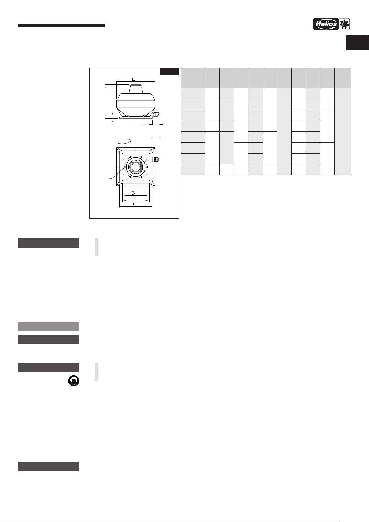
3.2 Abmessungen
Baureihe VDD.. 315-710
VDD.. – Dachventilatoren
DE
m
WARNUNG
Abb.1
D
E
F
Y
LK
B
A
Alle Maße in mm
3.3 Elektrischer Anschluss
m WARNUNG
Vor allen Wartungs- und Installationsarbeiten oder vor Öffnen des Anschlussraums ist das Gerät allpolig
vom Netz zu trennen und gegen unerwünschtes Wiedereinschalten zu sichern!
– Der elektrische Anschluss, bzw. die Inbetriebnahme darf nur von einer autorisierten Elektrofachkraft entsprechend
den Angaben im Klemmenkasten / Revisionsschalter und den beiliegenden Anschlussplänen ausgeführt werden.
– Die einschlägigen Normen, Sicherheitsbestimmungen (z.B. DIN VDE 0100) sowie die Technischen Anschluss-
bedingungen der Energieversorgungsunternehmen sind unbedingt zu beachten!
– Netzform, Spannung und Frequenz müssen mit den Angaben des Leistungsschildes übereinstimmen.
– Die Motoren sind grundsätzlich für Rechtslauf im Rechtsdrehfeld (siehe Drehrichtungspfeil) verdrahtet.
– Schutzleiter, einschließlich zusätzlicher Potentialausgleichanschlüsse sind ordnungsgemäß zu installieren!
– Abdichtung des Anschlusskabels und festen Klemmsitz der Adern prüfen.
– Die Einführung der Zuleitung ist fachgerecht auszuführen! Die Anschlussleitung in den Klemmenkasten/
Revisionsschalter (IP 65) muss die evtl. auftretenden Schwingungen des Ventilators ausgleichen.
Type
VD 315
VD 355
VD 400
VD 450 730 590
VD 500
VD 560
VD 630
VD 710
y Ay
B Ø Cy D E F H Ø LK Y
580 450
645 535
925 750
1260 1050
605
740 640 395
765 690 438
12
860 760 487
965
1070 1015 605
1155 1070 674
14
1365
30
40
65
136
570 356
790 541
1130 751
8 x
M8
6 x
M8
8 x
M10
elektr.
An-
schluss
X
Revisionsschalter
m
m
nmr
m
HINWEIS
ACHTUNG
WARNUNG
ACHTUNG
+
l
Installationszubehör für den Klemmkasten/Revisionsschalter muss der Anforderung IP65 entsprechen.
Leitung nie über scharfe Kanten führen!
3.4 Inbetriebnahme
m WARNUNG
Das drehende Laufrad kann Ihre Finger quetschen.
Vor der Inbetriebnahme Berührungsschutz sicherstellen!
Folgende Kontrollarbeiten sind vor der Erstinbetriebnahme auszuführen bzw. zu prüfen:
– Bestimmungsgemäßen Einsatz des Ventilators überprüfen
– Zulässige Fördermitteltemperatur prüfen
– Netzspannung mit Leistungsschildangabe vergleichen
– Ventilator auf fachgerechte elektrische Installation prüfen
– Schutzleiteranschluss prüfen
– Montagerückstände aus Ventilator bzw. Kanal entfernen
– Alle Teile, insbesondere Schrauben, Muttern und Schutzgitter auf festen Sitz überprüfen. Schrauben dabei nicht
lösen! Es dürfen sich keine losen Teile im Ventilator befinden.
– Ventilator auf Standsicherheit prüfen! Auf freie Zugänglichkeit zu Klemmenkasten / Revisionsschalter und
Motorlaufradeinheit ist zu achten.
– Sicherstellen, dass der Ansaug- und Ausblasbereich nicht für unbefugte Personen zugänglich ist.
– Dichtheit aller Verbindungen prüfen (falls erforderlich)
– Freilauf und Drehrichtung des Laufrades durch kurzzeitiges Einschalten prüfen; beim Prüfen Schutzbrille tragen.
– Stromaufnahme mit Leistungsschildangabe vergleichen
– Motorschutzeinrichtung auf Funktion testen. Beim Probelauf den Ventilator auf Vibrationen und Geräusche prüfen.
Bei übermäßigen Vibrationen und/oder Geräuschen, ist von einem Betrieb außerhalb des Betriebsbereichs des
Ventilators auszugehen. In diesem Fall ist unbedingt Kontakt mit dem Hersteller aufzunehmen!
5

Montage- und Betriebsvorschrift
3.5 Betrieb
m
WARNUNG
n
Regelmäßig die einwandfreie Funktion des Ventilators prüfen:
– Freilauf des Laufrades
– Stromaufnahme im Bereich der Typenschildangabe
– Prüfung auf eventuelle Schwingungen und Geräusche
– Ablagerungen von Staub und Schmutz im Gehäuse bzw. am Motor und Laufrad
– Bei Problemen mit einem der oben aufgeführten Punkte, ist eine Wartung nach den Anweisungen aus Kapitel 4
durchzuführen.
VDD.. – Dachventilatoren
– Abdichtung des Anschlusskabels in den Klemmenkasten und festen Klemmsitz der Adern prüfen
– Den Ventilator nicht außerhalb der angegebenen Kennlinie (siehe Katalog / Internet) betreiben. Der Ventilator muss
auf seinem vorgeschriebenen Betriebspunkt laufen.
– Um eine ausreichende Motorkühlung zu gewährleisten, ist bei Spannungssteuerung durch Phasenanschnitt eine
Mindestdrehzahl/Spannung, die auch von bauseitigen Widerständen, Winddruck etc. abhängig ist, einzuhalten.
Sie muss so gewählt werden, dass ein sicherer, ruckfreier Anlauf und Betrieb gewährleistet ist.
WARNUNG
m
Verberennungsgefahr!
Hohe Temperaturen am Ventilatorgehäuse können zu schweren Verbrennungen führen.
Geeignete Schutzhandschuhe tragen!
KAPITEL 4
INSTANDHALTUNG UND
WARTUNG
m
WARNUNG
nmr
4.0 Instandhaltung und Wartung
WARNUNG
m
Vor allen Wartungs- und Installationsarbeiten oder vor Öffnen des Anschlussraums ist das Gerät allpolig vom
Netz zu trennen und gegen unerwünschtes Wiedereinschalten zu sichern!
WARNUNG
m
Verberennungsgefahr!
Hohe Temperaturen am Ventilatorgehäuse können zu schweren Verbrennungen führen.
Geeignete Schutzhandschuhe tragen!
– Grundsätzlich sind die Geräte wartungsfrei. Alle dennoch notwendigen Wartungsarbeiten sind von autorisiertem
Fachpersonal vgl. Kapitel 1.6 durchzuführen!
– Übermäßige Ablagerungen von Schmutz, Staub, Fetten etc. auf Laufrad, Motor, Schutzgitter und vor allem
zwischen Gehäuse und Laufrad sind unzulässig, da sie zu Unwucht im Laufrad, Überhitzung des Motors oder zum
Blockieren des Laufrads führen können. In solchen Fällen ist das Gerät zu reinigen, siehe Punkt 4.1 Reinigung.
– Sofern das Gerät eine versorgungstechnisch wichtige Funktion übernimmt, ist eine einsatzabhängige regelmäßige
Wartung erforderlich. Im Falle längeren Stillstands ist bei Wiederinbetriebnahme eine Wartung durchzuführen.
– Zu prüfen sind:
• sichere Befestigung des Ventilators
• Schmutzablagerungen
• Beschädigungen
• Schraubverbindungen, insbesondere Laufradbefestigung. Schrauben dabei nicht lösen!
• Gehäuse-/Laufradoberflächenbeschichtung (z.B. auf Rost, Lackschäden)
• Freilauf des Laufrads
• Lagergeräusche
• Schwingungen, Vibrationen
• Stromaufnahme entsprechend dem Typenschild
• Funktion der Sicherheitsbauteile (z.B. Motorschutzschalter)
• Beschädigungen am Revisionsschalter
Die eingesetzten Kugellager sind bei normalen Betriebsbedingungen wartungsfrei und auf eine Lebensdauer von
20.000 h ausgelegt. Zur vorbeugenden Wartung sind die Kugellager aufgrund der Alterung des Fettes unabhängig von
den Betriebsstunden spätestens nach 5 Jahren zu wechseln.
m
WARNUNG
nm
m
l m p r n
ACHTUNG
4.1 Reinigung
m
Durch einen Isolationsfehler können Sie einen elektrischen Schlag bekommen!
Vor Beginn der Reinigung Ventilator allpolig vom Netz trennen und gegen Wiedereinschalten sichern!
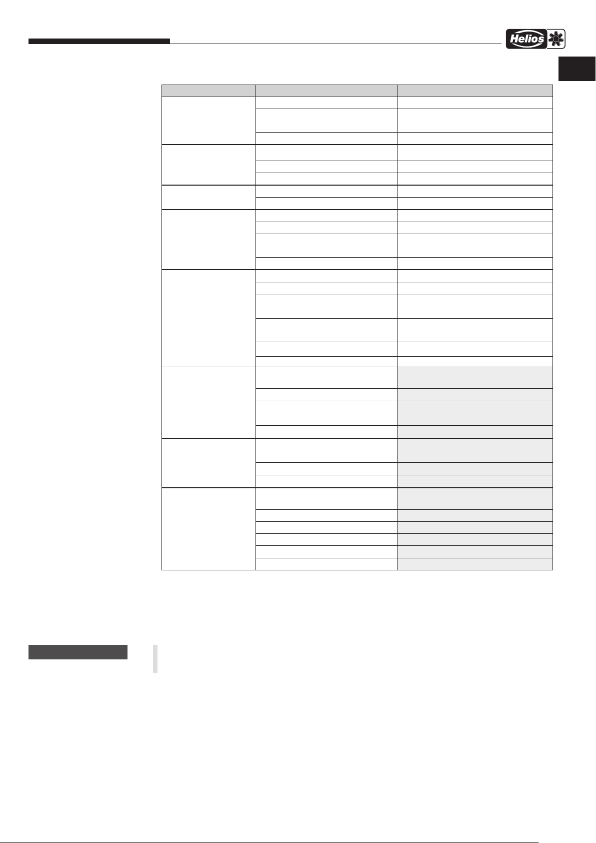
4.2 Hinweise – Störungsursachen
WARNUNG
– Für die Reinigung kann eine Demontage des Gerätes bzw. von Geräteteilen notwendig sein.
Diese ist von geeignetem Fachpersonal vgl. Kapitel 1.6 durchzuführen!
– Durchströmungsbereich, Laufrad, Verstrebung und Motor des Ventilators säubern.
– Keine aggressiven, lacklösenden Mittel verwenden!
– Hochdruckreiniger oder Strahlwasser sind nicht gestattet!
Es sind die in Kapitel 1, Punkt 1.2 aufgeführten Sicherheitshinweise zu beachten!
Die Beseitigung von Störungen darf nur von Fachpersonal vgl. Kapitel 1.6 durchgeführt werden!
6

Montage- und Betriebsvorschrift
VDD.. – Dachventilatoren
Fehler/Störung Ursachen Fehlerbehebung
Ventilator startet nicht keine Spannung, fehlen einer Phase Netzspannung prüfen
Laufrad blockiert Blockade lösen, reinigen,
Motor blockiert Motor prüfen, ggf. ersetzen
Sicherung löst aus Windungsschluss/Erdschluss im Motor Motor ersetzen
Zuleitung/Anschluss beschädigt Teile erneuern, ggf. Motor ersetzen
falsch angeschlossen Anschluss überprüfen, ändern
Fehlerstromschutzschalter löst aus
Motorschutzschalter
löst aus
Vibrationen Verschmutzung reinigen
Anormale Geräusche falscher Betriebspunkt Eignung des Ventilators prüfen,
zu hohe Stromaufnahme falscher Betriebspunkt Eignung des Ventilators prüfen,
Ventilator bringt die
Leistung (Drehzahl)
nicht
beschädigte Motorisolation Motor ersetzen
beschädigte Zuleitungsisolation Zuleitungen erneuern
schwergängige Lager Lager ersetzen
streifendes Laufrad reinigen, ggf. Laufrad ersetzen
falscher Betriebspunkt Eignung des Ventilators prüfen,
verschmutzter Motor reinigen
Lagerschäden Lager ersetzen
falscher Betriebspunkt Eignung des Ventilators prüfen,
befestigungsbedingte Resonanz Befestigung prüfen/ausbessern,
falsche Drehrichtung Anschluss prüfen / ändern
Laufrad hat Unwucht Nachwuchten durch Fachbetrieb
schleifendes Laufrad reinigen, ggf. ersetzen
Lagerschäden Lager ersetzen
mechanische Beschädigung Wartung durchführen
falsche Drehrichtung Anschluss prüfen / ändern
schleifendes Laufrad reinigen, ggf. ersetzen
Lagerschäden Lager ersetzen
falscher Betriebspunkt Eignung des Ventilators prüfen, Zu- und
falsche Spannung Anschluss prüfen/ändern
Lagerschäden Lager ersetzen
Verschmutzung reinigen
unzureichende Nachströmung Nachströmungsöffnungen erweitern
falsche Drehrichtung Anschluss prüfen / ändern
ggf. Laufrad ersetzen
Zu- und Abströmung prüfen/freihalten
Zu- und Abströmung prüfen/freihalten
Schwingungsdämpfer verwenden
Zu- und Abströmung prüfen/freihalten
Zu- und Abströmung prüfen/freihalten
Abströmung prüfen/freihalten
DE
m
WARNUNG
nm
4.3 Ersatzteile
Es sind ausschließlich Helios Originalersatzteile zu verwenden. Alle Reparaturen dürfen nur von autorisiertem/en
Fachpersonal/-Betrieben durchgeführt werden.
4.4 Stilllegen und Entsorgen
Bei der Demontage werden spannungsführende Teile freigelegt, die bei Berührung zu einem elektrischen
Schlag führen. Vor der Demontage Ventilator allpolig vom Netz trennen und gegen Wiedereinschalten sichern!
– Zur Stilllegung des Motors, Anweisungen aus der Wartungsanleitung des Elektromotors beachten
– Die Ventilatorkomponenten entsprechend den gültigen Vorschriften und Gesetzen entsorgen
WARNUNG
m
Die allgemein gültigen Arbeitsschutz- und Unfallverhütungsvorschriften sind einzuhalten!
– Elektroarbeiten dürfen nur von einer autorisierten Elektrofachkraft durchgeführt werden
– Elektroanschluss allpolig vom Netz trennen
– Geeignete Hebewerkzeuge und Befestigungsvorrichtungen zum Demontieren des Ventilators verwenden
7

Montage- und Betriebsvorschrift
VDD.. – Dachventilatoren
KAPITEL 5
TECHNISCHE DATEN
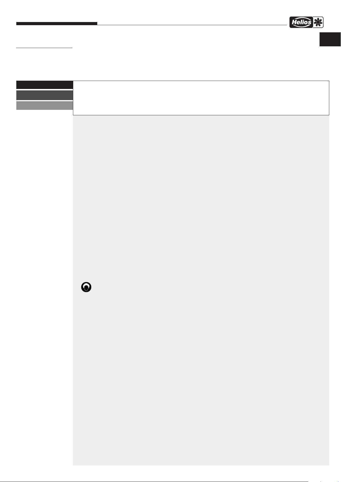
5.0 Technische Daten
Die produktspezifischen Technischen Daten sind dem Typenschild zu entnehmen. Nachfolgend sind die einzelnen
Angaben anhand eines Beispiels erläutert.
Abb.3
HELIOS VENTILATOREN GmbH + Co KG
Lupfenstraße 8, 78056 Villingen-Schwenningen, Germany
e
Type: VDD 630/6 T120
t
400/690 V D/Y
980 1/min
Einsatz und Betrieb nur gemäß Instruktions-Nr.
Operation only according to instruction no.
Utilisation uniquement selon instruction no.
Zeichenschlüssel Typenschild Ventilator:
q Herstelleradresse y Nennstrom
w Kennzeichnung der Ventilatoren: u aufgenommene Nennleistung
CE = CE-Zeichen i max. Umgebungs-, Fördermitteltemperatur bei Nennbetrieb
e Ausführung: Nenndrehzahl
VDD = Typenbezeichnung; Drehstrom Schutzart / Motorisolationsklasse / Kondensator
630 = Baugröße Gewicht
/6 = polig
r Artikelnummer / Produktionscode
t Nennspannung / Frequenz
50 Hz
IP55
r
Art.-Nr.: 7456 001
y
10 A
Iso.cl. F
27 199
u
4,0 kW
q
PC 08510
i
TN 120 °C
125 kg
w
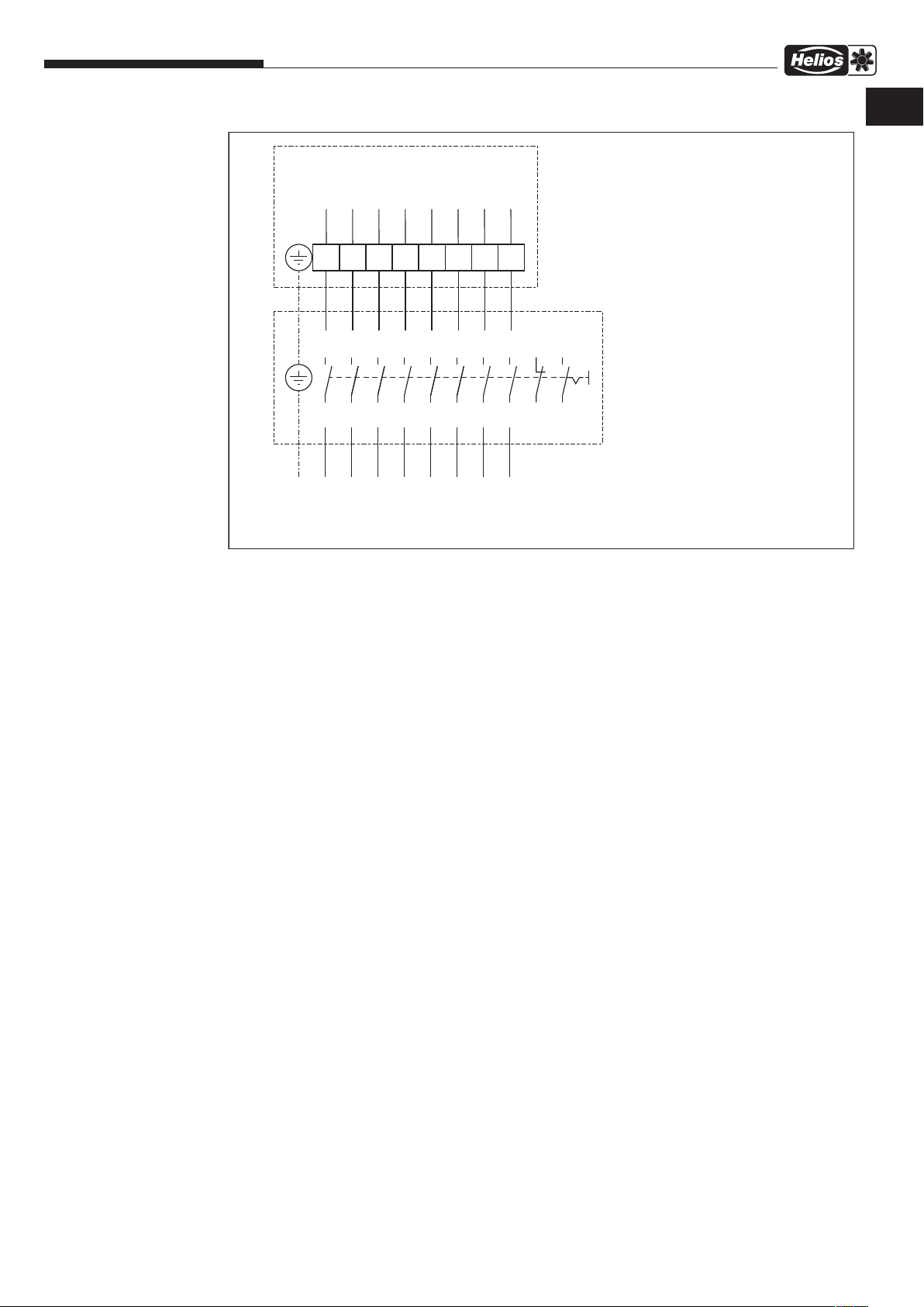
KAPITEL 6
SCHALTPLAN-ÜBERSICHT
SS-1296
VDD 315/4 T120
VDD 355/4 T120
VDD 400/4 T120
VDD 400/6 T120
VDD 450/4 T120
VDD 450/6 T120
VDD 500/6 T120
VDD 560/6 T120
6.0 Schaltpläne
3~ Motor
M
3
10
9
L3
5
12
11
TK
2
1
2
4
3
1
6
5
L1
8
7
L2
mit TB (TK)
6
14
13
TK
PE
RS 3+1+2
85499 058 SS-1296 23.02.18
8
Montage- und Betriebsvorschrift
SS-1130
VDD 500/4 T120
VDD 560/4 T120
VDD 630/6 T120
VDD 710/6 T120
VDD.. – Dachventilatoren
TB/TP
TB/TP
W2
V2
U2
W1
V1
3~ Motor
mit TB/TP (TK/KL)
U1
DE
Farbcode nach IEC 757
PE
TP
TB/
TB/
8
7
20
19
TB/TP
TP
W2
6
16
18
15
17
W2
TB/TP
5
V2
14
13
V2
4
U2
12
11
U2
3
W1
10
9
W1
2
V1
8
7
V1
1
U1
6
5
U1
U1 BN-br-braun-brown
V1 BU-bl-blau-blue
W1 BK-sw-schwarz-black
U2 RD-rt- rot-red
V2 GY-gr-grau-grey
4
2
3
1
W2 OG-or-orange-orange
TB/TP WH-ws-weiß-white
PE YE-GN-ge-gn-gelb-grün
-yellow-green
Schalter
85419 001 SS-1130 14.09.16
9
ENGLISH
Table of Contents
CHAPTER 1. SAFETY ...................................................................... Page 1
1.0 Important information ................................................................... Page 1
1.1 Warning instructions .................................................................... Page 1
1.2 Safety instructions ...................................................................... Page 1
1.3 Area of application ..................................................................... Page 2
1.4 Boundaries ........................................................................... Page 2
1.5 Protection against contact ............................................................... Page 2
1.6 Personnel qualification .................................................................. Page 3
1.7 Air-flow direction and direction of rotation .................................................... Page 3
1.8 Speed control with speed potentiometer (PU/A) ............................................... Page 3
1.9 Motor protection device ................................................................. Page 3
1.10 Functional safety – Emergency operation .................................................... Page 3
CHAPTER 2. GENERAL INFORMATION ....................................................... Page 3
2.0 Warranty claims – Exclusion of liability ...................................................... Page 3
2.1 Certificates - Guidelines ................................................................. Page 3
2.2 Shipping ............................................................................. Page 3
2.3 Receipt .............................................................................. Page 3
2.4 Storage .............................................................................. Page 4
2.5 Series ............................................................................... Page 4
2.6 Performance data ...................................................................... Page 4
2.7 Noise data ........................................................................... Page 4
CHAPTER 3. INSTALLATION ................................................................ Page 4
3.0 Installation ............................................................................ Page 4
3.1 Mounting ............................................................................. Page 4
3.2 Dimensions ........................................................................... Page 5
3.3 Electrical connection .................................................................... Page 5
3.4 Commissioning ........................................................................ Page 5
3.5 Operation ............................................................................ Page 6
CHAPTER 4. SERVICING AND MAINTENANCE ................................................. Page 6
4.0 Servicing and maintenance ............................................................... Page 6
4.1 Cleaning ............................................................................. Page 6
4.2 Information – Fault causes ............................................................... Page 6
4.3 Spare parts ........................................................................... Page 7
4.4 Standstill and disposal .................................................................. Page 7
CHAPTER 5. TECHNICAL DATA .............................................................. Page 8
5.0 Technical data ........................................................................ Page 8
CHAPTER 6. WIRING DIAGRAM OVERVIEW .................................................... Page 8
6.0 Wiring diagrams ....................................................................... Page 8
Expiry of service life, disposal
Parts and components of the fan, whose service life has expired, e.g. due to wear and tear, corrosion, mechanical load, fatigue and/or other effects that cannot be
directly discerned, must be disposed of expertly and properly after disassembly in accordance with the national and international laws and regulations. The same also
applies to auxiliary materials in use. Such as oils and greases or other substances.
The intended and unintended further use of worn parts, e.g. impellers, rolling bearings, filters, etc. can result in danger to persons, the environment as well as machines
and systems. The corresponding operator guidelines applicable on-site must be observed and used.

Installation and Operating Instructions
CHAPTER 1
SAFETY
1.0 Important information
VDD.. – Roof Fans
EN
In order to ensure complete and effective operation and for your own safety, all of the following instructions should be
read carefully and observed.
This document should be regarded as part of the product and as such should be kept accessible and durable to ensure
the safe operation of the fan. All plant-related safety regulations must be observed.
m
m
m
DANGER
WARNING
CAUTION
1.1 Warning instructions
The adjacent symbols are safety-relevant prominent warning symbols. All
safety regulations and/or symbols must be absolutely adhered to, so that
any risks of injury and dangerous situations are avoided!
1.2 Safety instructions
Protective glasses
l
Serves to protect against eye injuries.
Ear protectors
p
Serves to protect against all kinds of noise.
Protective clothing
r
Primarily serves to protect against contact with moving parts.
Do not wear rings, chains or other jewellery..
Protective gloves
n
Protective gloves serve to protect the hands against rubbing, abrasions, cuts
or more profound injuries, as well as contact with hot surfaces.
Protective footwear
m
Protective footwear serves to protect against heavy falling parts and from slip ping on slippery surfaces.
Hair net
The hair net primarily serves to protect long hair against contact with moving
parts.
Special regulations apply for use, connection and operation; consultation is re quired in case of doubt. Further information can be found in the relevant stan dards and legal texts.
m
and accident prevention regulations must be observed!
With regard to all work on the fan, the generally applicable safety at work
• Do not transport fan on the connection cables, terminal box or impeller! Do
not stand under suspended loads!
• All electrical work and the commissioning must only be carried out by au-
thorised, qualified electricians! Installation, servicing and maintenance work
must only be carried out by suitable specialist personnel!
• The following must be observed before all cleaning, maintenance and instal-
lation work or before opening the terminal compartment:
- Isolate the device from the mains power supply!
- The rotating parts must first come to a standstill!
- The unit must be secured against being switched on again!
• Only transport roof fans using means of transport that are appropriate for the
weight, wear protective gloves during transport!
• Wear gloves/protective footwear when unpacking the unit.
1

Installation and Operating Instructions
VDD.. – Roof Fans
• Ensure the suitable load capacity and properties of the mounting surface
and use suitable mounting material.
• Depending on the fan size, ear protectors may be necessary when working
or standing near the running fan!
• All plant-related safety regulations must be observed! If applicable, further
country-specific regulations must also be observed!
• Protection against contact must be ensured pursuant to DIN EN 13857 in
the installed condition (section 1.5)! Contact with rotating parts must be
avoided.
• It must be ensured that there must be no persons, textiles or other mate-
rials that could be sucked up, such as clothing, located in the intake area.
Furthermore, the outlet area must be kept free from objects and material that
could be ejected.
• Easy accessibility for inspection and cleaning personnel must be ensured, other
persons must not have access to the fan!
• A uniform inflow and free outlet must be ensured!
• A motor protection device (accessories) is absolutely essential for all motors
(except Ø 315, 355 and 400/6)!
* The maximum transport media temperature
of the respective unit can be found in the
currently applicable Helios sales documents.
m
WARNING
1.3 Area of application
- Normal use:
The conveying of normal or slightly dusty (particle size < 10 µm), less aggressive and humid air, in moderate climates
at temperatures in the range from -20 °C to max +120 °C, with stationary installation of the fan.
Installation: Horizontal on roofs (chapter 3.0), inaccessible to unauthorised persons.
– Reasonably foreseeable misuse:
The fans are not suitable for operation under difficult conditions, such as high levels of humidity, aggressive media,
long standstill periods, heavy contamination, excessive loads due to climatic, technical or electronic influences. The
same applies for the mobile use of fans (vehicles, aircraft, ships, etc.). The motor sizing was carried out for permanent operation pursuant to S1 and rules out high starting frequency. It must be ensured that the intended area of
application is adhered to.
– Improper, prohibited use:
The conveying of explosive gas mixtures/media. Installation in an explosive area/atmosphere. Operation without
standardised safety devices (e.g. protection guard). The conveying of solids or solid content > 10 µm in the transport
media and liquids. The conveying of abrasive and/or media that is corrosive to the fan materials. The conveying of
greasy transport media. Vertical (hanging) installation of the roof fan.
1.4 Boundaries
Spatial boundaries:
A straight, flat pipe section or free suction must be ensured for the suction area. The outlet area must not be
blocked, a minimum distance of 1 m from the fan must be observed. The fan must be easily accessible for cleaning
and maintenance purposes, particularly the terminal box/isolator switch.
Power supply interface:
– Connection only with permanently installed lines
– 3 phases + PE + 2x TB (TK) or TP (KL)
– A motor protection device (accessories) is absolutely essential for all motors (except Ø 315, 355 and 400/6)!
1.5 Protection against contact
The generally applicable safety at work and accident prevention regulations must be observed for installation!
The operator is responsible for observing these regulations!
– Contact with rotating parts must be avoided. It must be ensured that there must be no persons, textiles or other
materials that could be sucked up, such as clothing, located in the intake area.
– Protection against contact may be necessary on the suction side depending on the installation conditions.
– Fans which are protected by their installation method (e.g. installation in ventilation ducts or closed assemblies) do
not require protection guards if the plant provides the necessary level of safety. Please note that the operator is
responsible for complying with the current standard (DIN EN 13857) and can be held liable for accidents as a con sequence of missing protection systems.
1.6 Personnel qualification
– All electrical work as well as the start-up must only be carried out by qualified electricians.
– Installation, servicing and maintenance may be carried out by specialists (e.g.: industrial mechanics, mechatronics
engineers, metal workers or persons with comparable training) with the exception of electrical work.
2
Installation and Operating Instructions
1.7 Air-flow direction and direction of rotation
VDD.. – Roof Fans
EN
m
m
m
m
* The associated control units can be found
in the currently applicable Helios sales
documents.
m
* The associated motor protection devices
can be found in the currently applicable
Helios sales documents.
WARNING
n
l
WARNUNG
ATTENTION
ATTENTION
ATTENTION
m WARNING
Parts ejected from the fan may damage your eyes!
Wear protective glass when checking the direction of rotation!
m WARNING
The rotating impeller can sever or trap your fingers/arms!
Operation only with mounted safety fittings!
Do not insert objects into the rotating impeller! Risk of damage!
The roof fans have a fixed direction of rotation and air-flow direction (they are not reversible), which is indicated by an
arrow on the device reverse operation not possible)!
The direction of rotation may only be checked when the fan is switched off and coasting!
1.8 Speed control*
All fans of type..D can be speed-controlled in one of the following ways.
a) Transformer: All fans up to Ø 450 can be voltage-controlled by means of transformer.
b) Frequency inverter: All fans over Ø 500 can be speed-controlled with a frequency converter with sine filter.
The use of a frequency inverter without sine filter is only possible with approval from Helios.
The use of third party products, especially other electronic devices, can lead to functional problems, the des-
truction of the controller and/or fan. If control units are used, which have not been approved by Helios, all
warranty and liability claims shall lapse.
1.9 Motor protection device*
a) All 3 phase motors in fans Ø 400 (4-pole) and Ø 450 (4- and 6-pole) have thermal contacts wired on terminals. The
specifically developed motor protection device MD is recommended for connection.
b) All motors in fans over Ø 500 have PTC thermistors wired on terminals. The specifically developed motor protection
device MSA is recommended for connection.
c) All motors in fans Ø 315, Ø 355 and Ø 400 (6-polig) have integrated thermal contacts, which automatically deactivate
when the motor temperature is too high and reactivate after cooling down.
CHAPTER 2
GENERAL INFORMATION
m
WARNING
1.10 Functional safety – Emergency operation
When using the roof fan in an important supply function, the plant is to be designed so that emergency operation is
automatically guaranteed in case of fan failure. Suitable solutions are, for example,: parallel operation of two less pow erful units with a separate electric circuit, standby fan, alarm systems and emergency ventilation systems.
2.0 Warranty claims – Exclusion of liability
All versions of this documentation must be observed, otherwise the warranty shall cease to apply. The same applies
to liability claims against Helios. The use of accessory parts, which are not recommended or offered by Helios, is not
permitted. Any possible damages are not covered by the warranty. Changes and modifications to the unit are not per-
mitted and lead to a loss of conformity, and any warranty and liability shall be excluded in this case.
2.1 Regulations - Guidelines
If the product is installed correctly and used to its intended purpose, it conforms to all applicable provisions and EU
guidelines at its date of manufacture.
2.2 Shipping
The fan is packed ex works in such a way that it is protected against normal transport strain. Carry out the shipping
carefully. It is recommended to leave the fan in the original packaging. The fan must be kept in the casing or the provided lifting lugs (over Ø 450) for transportation or installation. In this respect, only use appropriate lifting equipment and
fastening devices. Weight information can be found on the label on the unit.
Do not transport fan on the connection cables, terminal box or impeller!
Do not stand under suspended loads!
2.3 Receipt
The shipment must be checked for damage and correctness immediately upon delivery. If there is any damage,
promptly report the damage with the assistance of the transport company. If complaints are not made within the agreed
period, any claims could be lost.
2.4 Storage
When storing for a prolonged time, the following steps are to be taken to avoid damaging influences: Motor protection by
dry, airtight and dust-proof packaging (plastic bag with desiccant and humidity indicators). Vibration-free, water-tight and
constant-temperature storage at a temperature in the range -20 °C to +40 °C, which must not be exceeded. In case of
a storage period of more than three months or motor standstill, maintenance must be carried out before start-up accor-
3
Installation and Operating Instructions
ding to chapter 8. In case of reshipment (above all, over longer distances; e.g. by sea), it must be checked whether the
packaging is suitable for the form and route of transport. Damages due to improper transportation, storage or putting into
operation are not liable for warranty.
2.5 Series
These installation and operating instructions describe the following Helios roof fan series:
Binding information on the individual fan types can be found on the type plate.
2.6 Performance data
output.
VDD.. – Roof Fans
Series Version Diameter
Vertical Roof Fans VDD.. T120 315 - 710 mm
The unit type plate gives an indication of the mandatory electrical values; which must be coordinated with the local
supply network. The fan performances* were established on a test stand according to DIN EN ISO 5801: 2010-12; they
apply to the nominal speed and standard design using an inlet nozzle, without a protection guard and with unhindered
inflow and outflow. Different versions and unfavourable installation and operating conditions can lead to a reduction of
* (performance and noise data can be found
in the current Helios publications and on the
internet)
CHAPTER 3
INSTALLATION
2.7 Noise data
The noise data* also refers to the directive mentioned in section 1.4. Housing variations, unfavourable operating con-
ditions and many other things can lead to an increase in the specified catalogue values. Data that refers to certain di stances (1, 2, 4 m) apply to free field conditions. With regard to installation, the sound pressure level can differ signifi cantly from the catalogue data, as it is highly dependent on the installation conditions, i.e. on the absorption capability
of the room, the room size among other factors.
3.0 Installation
The installation site must be suitable for the roof fan in type, composition, ambient temperature and ambient medium.
The substructure must be level and sufficiently load bearing. The mounting elements should be as level as possible
(max. 5 % incline), however, installation on inclined surfaces up to 45° angle of inclination is possible (e.g. pitched
roof base type SDS, Accessories).
3.1 Mounting
The roof fans are designed for base installation. The base plate of the fan has 4 holes for mounting to the base.
Place the fan with the base plate on the base (see Accessories). In this respect, observe the respective
installation and operating instructions for flat roof bases. Tighten the anchor screws equally to avoid warping.
NOTE: If a VDD 710/6 is installed in combination with a backdraught shutter (RVS/RVM 710), an extension
duct (VR 710) is required between the unit and the backdraught shutter.
NOTE: An extension duct (VR 710) is not required with a hinged base attenuator (SSD 710).
4

H
D
E
F
H
C
Installation and Operating Instructions
3.2 Dimensions
Series VDD.. 315-710
VDD.. – Roof Fans
EN
m
WARNING
Fig.1
D
E
F
Y
LK
B
A
All dimensions in mm
3.3 Electrical connection
m WARNING
The fan must be isolated from the mains power supply and secure against being switched on again before
all maintenance and installation work or before opening the terminal compartment!
– The electrical connection and start-up must only be carried out by qualified electricians according to the information
in the terminal box / isolator switch and the attached wiring diagrams.
– All relevant standards, safety regulations (e.g. DIN VDE 0100), as well as the technical connection conditions of
energy suppliers are to be adhered to!
– Network configuration, voltage and frequency must be consistent with the rating plate information.
– In principle, the motors are wired in the clockwise field of rotation for clockwise rotation.
– Protective conductors, including additional equipotential bonding, must be properly installed!
– Check the waterproofing of the connection cable and tight clamping of the strands.
– The insertion of the supply line must be carried out by specialists! The connection line in the terminal box/ isolator
switch (IP 65) must compensate for the potential fan vibrations.
Type
VD 315
VD 355
VD 400
VD 450 730 590
VD 500
VD 560
VD 630
VD 710
y Ay
B Ø Cy D E F H Ø LK Y
580 450
645 535
925 750
1260 1050
605
740 640 395
765 690 438
12
860 760 487
965
1070 1015 605
1155 1070 674
14
1365
30
40
65
136
570 356
790 541
1130 751
8 x
M8
6 x
M8
8 x
M10
electr.
connec-
tion
X
Isolator
m
m
nmr
m
NOTE
+
ATTENTION
WARNING
ATTENTION
l
Installation accessories for the terminal box/isolator switch must meet the requirements of IP 65.
Never lay cables over sharp edges!
3.4 Commissioning
m WARNING
The rotating impeller can crush fingers.
Ensure protection against contact before commissioning!
The following inspection work must be carried out or checked before commissioning:
– Check designated use of fan
– Check permissible transport media temperature
– Compare power consumption to rating plate data
– Check fan for professional electrical installation
– Check protective conductor connection
– Remove installation residues from the fan or duct
– Check all parts for tightness, particularly screws, nuts, protection guards. Do not loosen screws in the process!
Loose parts must not enter the fan.
– Check fan for solid mounting! The terminal box / isolator switch and motorised impeller unit must be freely acces-
sible.
– Ensure that the suction and outlet areas cannot be accessed by unauthorised persons.
– Check tightness of all connections (if necessary)
– Check free movement and direction of rotation of impeller by briefly switching on; Wear protective glasses when
checking.
– Compare power consumption to rating plate data
– Check fan for vibration and noise during test run. In case of excessive vibration and/or noise, it can be assumed that
the fan is operating outside of its operating range. In this case, contact the manufacturer by all means!
5

Installation and Operating Instructions
3.5 Operation
m
WARNING
n
Regularly check the proper functioning of the fan:
– Free movement of the impeller
– Power consumption in the range of the type plate data
– Check any vibrations and noises
– Formation of dust or dirt deposits in the casing or on the motor and impeller
– In case of problems with one of the aforementioned points, maintenance must be carried out according to the inst ructions in chapter 4.
VDD.. – Roof Fans
– Check the waterproofing of the connection cable and tight clamping of the strands.
– Do not operate fan outside of specified characteristic curve (see catalogue / internet) . The fan must run at its spe-
cified operating point.
– In order to ensure sufficient motor cooling, a minimum speed/voltage, which also depends on on-site resistances,
wind pressure, etc., must be observed for voltage controlling through phase control. It must be selected so that a
safe, jolt-free start-up and operation are ensured.
WARNING
m
Risk of burns!
The high temperatures at the fan housing can lead to severe burns.
Wear suitable protective gloves!
CHAPTER 4
SERVICING AND
MAINTENANCE
m
nmr
WARNING
4.0 Servicing and maintenance
WARNING
m
The fan must be isolated from the mains power supply and secure against being switched on again before all
cleaning, maintenance and installation work or before opening the terminal compartment!
WARNING
m
Risk of burns!
The high temperatures at the fan housing can lead to severe burns.
Wear suitable protective gloves!
– In principle, the units are maintenance-free. Nevertheless, all necessary maintenance work must be carried out by
qualified electricians, cf. section 1.6!
– Excessive deposits of dirt, dust, grease, etc. on the impeller, motor, protection guard and, above all, between the
housing and the impeller, are not permitted, as these can lead to an unbalance in the impeller, overheating of the
motor or the blocking of the impeller. In such cases, the unit must be cleaned, see section 4.1 Cleaning.
– If the fan has an important supply function, irregular performance-related maintenance is necessary. In cases of
longer periods of standstill, maintenance must be carried out when the unit is restarted.
– The following must be checked:
• Secure mounting of the fan
• Dirt deposits
• Damage
• Tightness of screw connections, particularly impeller mounting. Do not loosen screws in the process!
• Housing/impeller surface coatings (e.g. rust, paint defects)
• Free movement of the impeller
• Bearing noises
• Oscillations, vibrations
• Current consumption according to type plate
• Functionality of safety components (e.g. motor protection switch)
• Damage to isolator switch
The ball bearings used are maintenance-free under normal operating conditions and they are designed for a service life
of 20,000 hours. Regardless of the operating hours, the ball bearings must be replaced after 5 years at the latest due
to the ageing of the grease for reasons of preventative maintenance.
m
WARNING
nm
m
l m p r n
ATTENTION
4.1 Cleaning
m
An insulation fault may result in electric shock!
Before cleaning, isolate the fan from the mains power supply and protect against being switching on again!
4.2 Information – Fault causes
WARNING
– The disassembly of the unit or parts of the unit may be necessary for the cleaning.
This must be carried out by suitable specialist personnel cf. section 1.6!
– Clean fan flow area as well as impeller and motor.
– Do not use aggressive cleaning agents that could damage the paintwork!
– High pressure cleaners or water jets are not permitted!
The safety instructions specified in chapter 1, section 1.2 must be observed!
The elimination of faults must only be carried out by specialist personnel, cf. chapter 1.6!
6
Installation and Operating Instructions
VDD.. – Roof Fans
Error/fault Causes Solution
Fan does not start No voltage, phase missing Check mains voltage
Impeller blocked Clear blockage, clean, replace impeller if
Motor blocked Check motor, replace if necessary
Fuse tripped Short-circuited coil/ground fault in
Residual current device
tripped
Motor protection switch
triggered
Vibrations Contamination Clean
Abnormal noises Incorrect operating point Check suitability of fan, Check/keep inflow
Power consumption too
high
Fan does not perform
(speed)
motor
Supply line/connection damaged Replace parts, replace motor if necessary
Connected incorrectly Check connection, change
Motor insulation damaged Replace motor
Supply line insulation damaged Replace supply lines
Tight bearing Replace bearing
Impeller touching Clean, replace impeller if necessary
Incorrect operating point Check suitability of fan, Check/keep inflow
Contaminated motor Clean
Bearing damage Replace bearing
Incorrect operating point Check suitability of fan, Check/keep inflow
Attachment-related resonance Check or repair attachment, use vibration
incorrect direction of rotation Check / change connection
Impeller out of balance Rebalance by specialist
Grinding impeller Clean, replace if necessary
Bearing damage Replace bearing
Mechanical damage Carry out maintenance
Incorrect direction of rotation Check / change connection
Incorrect operating point Check suitability of fan, Check/keep inflow
Grinding impeller Clean, replace if necessary
Bearing damage Replace bearing
Incorrect operating point Check suitability of fan, Check/keep inflow
Incorrect voltage Check/modify connection
Bearing damage Replace bearing
Contamination Clean
Insufficient backflow Widen backflow openings
Incorrect direction of rotation Check / change connection
necessary
Replace motor
and outflow clear
and outflow clear
damper
and outflow clear
and outflow clear
and outflow clear
EN
m
WARNING
nm
4.3 Spare parts
Only original Helios spare parts are to be used. All repairs may only be carried out by authorised specialist personnel/
companies.
4.4 Standstill and disposal
When dismantling, live parts can be exposed, which can result in electric shock if touched. Before dismant-
ling, isolate the unit from the mains power supply and protect against being switching on again!
– Observe the instructions in the electric motor maintenance manual for decommissioning the motor
– Dispose of the fan components according to the valid rules and laws
WARNING
m
The generally applicable safety at work and accident prevention regulations must be observed!
– Electrical work must only be carried out by an authorised electrician
– Fully isolate electrical connection from mains power supply
– Use appropriate lifting equipment and fastening devices to dismantle the fan
7

Installation and Operating Instructions
VDD.. – Roof Fans
CHAPTER 5
TECHNICAL DATA
5.0 Technical data
The product-specific technical data can be found on the type plate. The individual data is described below using an
example.
HELIOS VENTILATOREN GmbH + Co KG
Lupfenstraße 8, 78056 Villingen-Schwenningen, Germany
e
Type: VDD 630/6 T120
t
400/690 V D/Y
980 1/min
Einsatz und Betrieb nur gemäß Instruktions-Nr.
Operation only according to instruction no.
Utilisation uniquement selon instruction no.
Character key Type plate Fan:
q Manufacturer‘s address y Nominal current
w Fan mark: u recorded nominal power
CE = CE mark i max. ambient, transport media temp. at nominal operation
e Version: Nominal speed
VDD = type designation; alternating current Protection category / motor insulation class
630 = size Weight
/6 = pole
r Article number / Production code
t Nominal voltage / frequency
50 Hz
IP55
r
Art.-Nr.: 7456 001
y
10 A
Iso.cl. F
27 199
u
4,0 kW
q
PC 08510
i
TN 120 °C
125 kg
w
Fig.3
CHAPTER 6
WIRING DIAGRAM
OVERVIEW
SS-1296
VDD 315/4 T120
VDD 355/4 T120
VDD 400/4 T120
VDD 400/6 T120
VDD 450/4 T120
VDD 450/6 T120
VDD 500/6 T120
VDD 560/6 T120
6.0 Wiring diagrams
3~ Motor
M
3
10
9
L3
5
12
11
TK
2
1
2
4
3
1
6
5
L1
8
7
L2
mit TB (TK)
6
14
13
TK
PE
RS 3+1+2
85499 058 SS-1296 23.02.18
8

Installation and Operating Instructions
SS-1130
VDD 500/4 T120
VDD 560/4 T120
VDD 630/6 T120
VDD 710/6 T120
VDD.. – Roof Fans
TB/TP
TB/TP
W2
V2
U2
W1
V1
3~ Motor
mit TB/TP (TK/KL)
U1
EN
Farbcode nach IEC 757
PE
TP
TB/
TB/
8
7
20
19
TB/TP
TP
W2
6
16
18
15
17
W2
TB/TP
5
V2
14
13
V2
4
U2
12
11
U2
3
W1
10
9
W1
2
V1
8
7
V1
1
U1
6
5
U1
U1 BN-br-braun-brown
V1 BU-bl-blau-blue
W1 BK-sw-schwarz-black
U2 RD-rt- rot-red
V2 GY-gr-grau-grey
4
2
3
1
W2 OG-or-orange-orange
TB/TP WH-ws-weiß-white
PE YE-GN-ge-gn-gelb-grün
-yellow-green
Schalter
85419 001 SS-1130 14.09.16
9

Notice de montage et d’utilisation
FRANÇAIS
Sommaire
CHAPITRE 1 SÉCURITÉ .................................................................... Page 1
1.0 Informations importantes. . . . . . . . . . . . . . . . . . . . . . . . . . . . . . . . . . . . . . . . . . . . . . . . . . . . . . . . . . . . . . . . . Page 1
1.1 Mises en garde ........................................................................ Page 1
1.2 Consignes de sécurité .................................................................. Page 1
1.3 Domaine d’utilisation .................................................................... Page 2
1.4 Restrictions ........................................................................... Page 2
1.5 Protection contre tout contact accidentel .................................................... Page 2
1.6 Qualification du personnel ................................................................ Page 3
1.7 Sens de l’écoulement de l’air et de la rotation. . . . . . . . . . . . . . . . . . . . . . . . . . . . . . . . . . . . . . . . . . . . . . . . . Page 3
1.8 Réglage de la vitesse ................................................................... Page 3
1.9 Protection moteur ...................................................................... Page 3
1.10 Sécurité de fonctionnement – Mode de secours ............................................... Page 3
CHAPITRE 2 INFORMATIONS GÉNÉRALES ....................................................Page 3
2.0 Demande de garantie – Réserves du constructeur ............................................. Page 3
2.1 Réglementations – Directives ............................................................. Page 3
2.2 Transport ............................................................................ Page 3
2.3 Réception de la marchandise ............................................................. Page 3
2.4 Stockage ............................................................................ Page 4
2.5 Modèle en série ....................................................................... Page 4
2.6 Performances ......................................................................... Page 4
2.7 Données acoustiques ................................................................... Page 4
CHAPITRE 3 MONTAGE .................................................................... Page 4
3.0 Installation ............................................................................Page 4
3.1 Fixation .............................................................................. Page 4
3.2 Dimensions ........................................................................... Page 5
3.3 Raccordement électrique ................................................................Page 5
3.4 Mise en service ........................................................................ Page 5
3.5 Fonctionnement ....................................................................... Page 6
VD.. – Tourelles de toitures
CHAPITRE 4 ENTRETIEN ET MAINTENANCE ................................................... Page 6
4.0 Entretien et maintenance ................................................................ Page 6
4.1 Nettoyage ............................................................................ Page 6
4.2 Indications des origines de dysfonctionnements ...............................................Page 6
4.3 Pièces de rechange .................................................................... Page 7
4.4 Mise hors service et mise au rebut ......................................................... Page 7
CHAPITRE 5 DONNÉES TECHNIQUES ........................................................ Page 8
5.0 Données techniques .................................................................... Page 8
CHAPITRE 6 SCHÉMAS DE RACCORDEMENT ................................................. Page 8
6.0 Schémas de raccordement ...............................................................Page 8
Matériel en fin de vie
Les pièces et composants du ventilateur arrivés en fin de vie (usure, corrosion, stress mécanique, dégradation et/ou autres effets qui ne seraient pas immédiatement
détectables) doivent être démontés, puis mis au rebut de façon professionnelle et compétente conformément aux lois et prescriptions nationales et internationales en
vigueur. Idem pour les produits consommables (huile, graisse, etc.).
La réutilisation volontaire ou involontaire de composants usagés ( turbines, roulements, courroies, etc.) peut représenter un danger pour les personnes, pour l’environnement ou encore pour les machines et les installations. Il est important de respecter et d’appliquer les réglementations locales en vigueur imposées aux exploitants.
Notice de montage et d’utilisation
CHAPITRE 1
SÉCURITÉ
1.0 Informations importantes
VD.. – Tourelles de toitures
FR
Il est important de bien lire et suivre l’ensemble des consignes suivantes pour le bon fonctionnement de l’appareil et
pour la sécurité des utilisateurs.
Ce document fait partie du produit et doit être conservé à proximité comme référence. L’exploitant est tenu de faire
respecter toutes les règles de sécurité relatives à l’installation.
m
m
m
DANGER
AVERTISSEMENT
PRUDENCE
1.1 Mises en garde
Les symboles ci-contre indiquent une consigne de sécurité. Toutes les
consignes de sécurité ainsi que les symboles doivent être impérativement
respectés, afin d’éviter toute situation dangereuse !
1.2 Consignes de sécurité
Lunettes de protection
l
Protèges contre les blessures oculaires.
Protection auditive
p
Protège contre tout type de bruits.
Vêtements de travail
r
Protègent contre le happement des pièces mobiles de la machine. Ne porter
ni bagues, ni colliers, ni autres bijoux.
Gants de protection
n
Les gants de protection protègent les mains de tout frottement, toute écorchure, piqûre ou autre blessure plus profonde.
Protègent aussi de tout contact avec des surfaces brûlantes.
Chaussures de sécurité
m
Protègent des chutes d’objets lourds et empêchent de tomber sur les sur
faces glissantes.
Filet à cheveux
Évite que les longs cheveux ne se prennent dans les parties mouvantes.
Le fonctionnement, le raccordement et l’utilisation relèvent de dispositions
spécifiques ; en cas de doute, nous contacter. Des informations
supplémentaires sont consultables dans les normes et textes de loi.
m
règles de sécurité afin d’éviter tout accident !
Lors de la manipulation du ventilateur, veiller à bien respecter les
• Ne pas transporter le ventilateur en le tenant par les câbles, la boîte à bornes
ou la turbine ! Ne pas rester sous une charge suspendue !
• Tous les travaux sur électricité ainsi que la mise en service ne doivent être
effectués que par un électricien qualifié ! Tous les travaux d’installation, de
maintenance et d’entretien ne doivent être effectués que par du personnel
qualifié.
• Avant tout travail de nettoyage, d’installation, d’entretien et de maintenance
ou avant l’ouverture de la boîte à bornes, vérifier les points suivants :
– Mettre tous les pôles de l’appareil hors tension !
– Attendre l’arrêt complet des éléments rotatifs !
– Vérifier que l’appareil est protégé contre tout redémarrage accidentel !
• Déplacer la tourelle de toiture avec un moyen de transport adéquat. Porter
des chaussures de sécurité lors du transport !
• Porter des gants de protection et des chaussures de sécurité lors du débal-
lage de l’appareil.
1

Notice de montage et d’utilisation
VD.. – Tourelles de toitures
• Vérifier les capacités de charge des fixations et utiliser les moyens de trans-
port appropriés.
• Si vous travaillez ou restez à proximité du ventilateur en marche, une protec-
tion auditive peut s'avérer nécessaire en fonction de la taille du ventilateur !
• Toutes les consignes d’installation sont à respecter ! Les réglementations
spécifiques nationales sont à respecter !
• La protection contre tout contact accidentel conformément à NF EN 13857
doit être assurée lors de l'installation (chapitre 1.5) ! Tout contact avec les
éléments rotatifs doit être évité.
• S'assurer qu'aucun corps étranger (personne, textile, etc.) ne se trouve dans
le champ d'aspiration. Aussi, aucun objet ou tissu ne doit se trouver dans le
champ d'évacuation car ils risquent d'être projetés.
• Garantir une accessibilité réduite pour le personnel d'inspection et d'entre-
tien, les autres personnes ne devant avoir aucun accès au ventilateur !
• Il convient de ménager une amenée d’air homogène et un rejet libre de l’air.
• Prévoir impérativement une protection moteur (accessoire) (saufØ 315, 355
et 400/6) !
* La température de flux max. de l’appareil est
à consulter dans la documentation commerciale Helios.
AVERTISSEMENT
m
1.3 Domaines d'utilisation
– Utilisation conforme :
Extraction d’air normalement pollué ou légèrement poussiéreux (taille des particules < 10 µm),
humide et contenant peu de particules agressives, en climat tempéré de -20 °C à +120 °C, en installation fixe.
Installation : à l'horizontale sur un toit (chapitre 3.0), inaccessible pour les personnes non autorisées.
– Utilisations inadéquates prévisibles
Les ventilateurs ne sont pas conçus pour fonctionner dans des conditions extrêmes, par exemple avec des fluides
agressifs, de longues phases d'arrêt, un encrassement important, un usage intensif lié aux conditions climatiques ou
soumis à des contraintes techniques et électroniques. Une utilisation en unité mobile (véhicules, avions, bateaux, etc.)
n’est pas prévue. Les caractéristiques moteur sont prévues pour un fonctionnement permanent (S1) et excluent des
démarrages intempestifs. Il faut veiller à bien respecter le domaine d’utilisation préconisé.
– Utilisation abusive, interdite :
Extraction de mélanges de gaz/fluides explosibles. Installation dans une zone/atmosphère explosible. Utilisation ne
respectant pas les normes de protection (par ex. grille de protection). Extraction de particules de matière solide de
taille >10 µm ainsi que les liquides. Extraction de matières corrosives et/ou détergentes. Installation verticale de la
tourelle de toiture.
1.4 Restrictions
Encombrement :
Prévoir un champ d’aspiration dégagé ou un conduit droit et lisse. La zone de refoulement ne doit pas être obstruée,
un espace de 1 m min. est à prévoir autour du ventilateur. Le ventilateur doit être facilement accessible
pour le nettoyage et la maintenance, en particulier la boîte à bornes/trappe de visite.
Raccordement de l’appareil :
– Le raccordement électrique doit être fixe et pérenne.
– 3 phases + PE + 2x TB (TK) et TP (KL)
– Prévoir impérativement une protection moteur totale (sauf Ø 315, 355 et 400/6) !
1.5 Protection contre tout contact accidentel
Lors du montage, veiller à bien respecter les règles de sécurité afin d’éviter tout accident !
Le respect de ces règles relève de la responsabilité de l’exploitant !
– Tout contact avec les éléments rotatifs doit être évité. S'assurer qu'aucun corps étranger (personne, textile, etc.)
ne se trouve dans le champ d'aspiration.
– Une protection contre tout contact peut être requise côté aspiration en fonction des conditions d’installation.
– Les ventilateurs protégés de par leur implantation (par ex. raccordements à des gaines) ne nécessitent pas de grille
de protection si le même niveau de sécurité est assuré. L’utilisateur est alors tenu de respecter la norme
actuelle (NF N 13857) et sera tenu responsable en cas d’accident résultant d’une infraction à ces dispositions.
1.6 Qualification du personnel
– Tous les travaux sur électricité ainsi que la mise en service ne doivent être effectués que par un électricien qualifié !
Les travaux d’installation, d’entretien et de maintenance, à l’exception des travaux d’électricité, ne doivent être effec
tués que par du personnel qualifié (par ex. : mécaniciens industriels, mécaniciens, serrurier ou similaire).
2

Notice de montage et d’utilisation
1.7 Sens de l’écoulement de l’air et de la rotation
VD.. – Tourelles de toitures
FR
m
m
m
m
* Les unités de commande sont disponibles
chez Helios.
m
* Les protections moteur sont disponibles
chez Helios.
AVERTISSEMENT
n
l
AVERTISSEMENT
ATTENTION
ATTENTION
ATTENTION
m AVERTISSEMENT
Le ventilateur peut projeter des éclats qui risquent de blesser vos yeux !
Porter des lunettes de protection lors du contrôle du sens de la rotation !
m AVERTISSEMENT
Risque de se coincer ou couper les doigts/bras dans la turbine en rotation !
Les équipements de protection sont obligatoires lors de toute manipulation !
Ne pas insérer d’objets dans la turbine en rotation. Risques de dégâts matériels !
Les tourelles de toitures ont un sens de rotation moteur défini, représenté par une flèche sur les appareils (pas d’in
version de sens possible). Un mauvais sens de rotation peut mener à une surchauffe et à un défaut de fonctionne
ment du ventilateur !
Le sens de rotation doit être vérifié seulement une fois que le ventilateur a été mis hors tension
et qu’il s’est arrêté de tourner.
1.8 Réglage de la vitesse*
La vitesse de toutes les tourelles de type D peuvent peut être réglée comme suit :
a) Transformateur : Tous les ventilateurs dont le diamètre atteint jusqu'à 450 sont régulables en tension par un transforma-
teur.
b) Variateur de fréquence : Tous les ventilateurs dont le diamètre est égal ou supérieur à 500 peuvent être régulés par un
variateur de fréquence avec filtre sinus.
L’utilisation d’un variateur de fréquence sans filtre sinus doit être approuvé par Helios.
L'utilisation d’accessoires d’un autre fabricant peut conduire à des problèmes de fonctionnement
de la régulation et/ou du ventilateur. Lors de l’utilisation d’une régulation non conseillée par Helios,
la garantie et les réserves constructeur s’annulent.
1.9 Protection moteur*
a) Tous les moteurs triphasés des ventilateurs de Ø 400 (4 pôles) et Ø 450(4 à 6 pôles) sont équipés thermocontacts
ramenés sur le bornier. qui doivent être raccordés à un appareil de protection totale MD pour les protéger contre tout
redémarrage intempestif.
b) Tous les moteurs des ventilateurs d'un Ø à partir de 500 sont équipés de thermistances ramenées
sur le bornier qui doivent être raccordés sur l'appareil de protection spécifique MSA.
c) Tous les moteurs des ventilateurs de Ø 315, Ø 355 et Ø 400 (6 pôles) sont équipés d'un thermocontact thermique
intégré qui arrête automatiquement la tourelle lorsque la température du moteur est trop élevée et la remet en marche
après refroidissement.
CHAPITRE 2
INFORMATIONS
GÉNÉRALES
AVERTISSEMENT
m
1.10 Sécurité de fonctionnement – Mode de secours
Si la tourelle de toiture a une fonction technique déterminante, l’installation doit être conçue de sorte qu’un système
de secours soit automatiquement assuré en cas de défaillance de l’appareil. Les solutions suivantes peuvent être
envisagées : fonctionnement simultané de deux appareils de performance inférieure sur deux enceintes séparées,
ventilateur en stand-by, dispositifs d’alarme et systèmes d’aération de secours.
2.0 Demande de garantie – Réserves du constructeur
Si toutes les consignes indiquées dans cette notice ne sont pas correctement respectées, la garantie s’annule. Idem
pour les réserves constructeur. L'utilisation d'accessoires non conseillés ou proposés par Helios n'est pas
permise. Les dégâts causés par une mauvaise utilisation ne sont pas inclus dans la garantie. Les changements et
transformations de l’appareil sont interdits et entraînent une perte de conformité : la garantie et la responsabilité du
fabricant s’annulent.
2.1 Réglementations – Normes
Sous d’une réserve d’une installation correcte et d’une utilisation appropriée, cet appareil est conforme aux directives
UE en vigueur au moment de sa fabrication.
2.2 Transport
Le ventilateur est emballé en usine de façon à être protégé des dégâts de transport courants. Transporter
l’appareil avec précaution. Il est conseillé de laisser le ventilateur dans son emballage d’origine. Pour le transport ou le montage, le ventilateur doit être saisi par le caisson ou par les anneaux de levage prévus à cet effet.
Utiliser un appareil de levage et des dispositifs de fixation adéquats. Le poids figure sur l’étiquette de l’appareil.
Ne pas transporter le ventilateur en le tenant par les câbles, la boîte à bornes ou la turbine !
Ne pas rester sous une charge suspendue !
2.3 Réception de la marchandise
Dès réception, vérifier l’état et la conformité du matériel commandé. En cas de dégâts, les signaler immédiatement
par lettre recommandée au transporteur. Attention, le non-respect de ces procédures peut entraîner le rejet de la
réclamation.
3

Notice de montage et d’utilisation
2.4 Stockage
Pour un stockage de longue durée et pour éviter toute détérioration préjudiciable, il convient de se conformer aux
instructions suivantes : Protéger le moteur avec un emballage sec, étanche à l’air et à la poussière (sac en matière
synthétique contenant des sachets déshydrateurs et un indicateur d’humidité). Stocker le matériel dans un endroit
abrité de l’eau, exempt de vibration et de variation de températures.
2.5 Modèle en série
Cette notice de montage et d’utilisation concernent les tourelles de toitures Helios des séries suivantes :
2.6 Performances
VD.. – Tourelles de toitures
Température de stockage entre -20 °C et +40 °C ; ces valeurs sont des seuils à ne pas dépasser. Si la durée de
stockage est supérieure à trois mois, une vérification est à effectuer sur le moteur avant toute mise en service.
Vérifier la rotation silencieuse et libre de la turbine. En cas de réexpédition (longues distances, voies maritimes, etc.),
vérifier que l’emballage est bien approprié aux conditions de transport. Les dommages dus à de mauvaises conditions de transport ou de stockage, ou encore à une utilisation anormale, sont vérifiables et ne sont pas couverts par
la garantie.
Série Version Diamètre
Tourelles de toitures verticales VDD.. T120 315 - 710 mm
Les informations spécifiques à un modèle se trouvent sur la plaque signalétique du produit.
La puissance électrique requise figure sur la plaque signalétique ; l’appareil doit être raccordé à l’alimentation électrique
locale. Les vitesses du ventilateur* ont été testées selon la norme NF EN ISO 5801 : 2010-12 ; elles s’appliquent au
courant nominal et à un modèle standard avec pavillon d’aspiration, sans grille de protection pour une aspiration et
une évacuation sans encombre. Si le modèle est différent, mal installé ou utilisé dans des conditions inappropriées, les
performances peuvent être réduites.
* (Pour les performances et données acoustiques,
se reporter aux documentations Helios
actuellement en vigueur et au site Internet)
CHAPITRE 3
MONTAGE
2.7 Données acoustiques
Les données acoustiques* se réfèrent aux consignes décrites dans le chapitre 1.4. Le mode de montage, des
conditions d’utilisation défavorables, etc. peuvent conduire à des valeurs plus élevées que celles indiquées dans le
catalogue. Les données ont été mesurées à différentes distances (1, 2 et 4 m) en champ libre. Le niveau sonore peut
varier par rapport aux spectres sonores indiqués dans le catalogue étant donné qu’il dépend, entre autres, du pouvoir
d’absorption de l'environnement et de la situation d’installation.-
3.0 Installation
La tourelle doit être installée à un endroit adapté à ses caractéristiques, en termes de résistance de la structure, de
température et d'ambiance. Le support doit être plan et suffisamment solide. Les plans de fixation doivent être les plus
horizontaux possibles (pente max. 5 %), un montage sur une surface inclinée jusqu’à 45° (avec par ex. un socle de toit
incliné type SDS, accessoire) est cependant admis.
3.1 Fixation
Les tourelles de toiture sont conçues pour un montage sur costière. Quatre percements se situent sur la plaque du
ventilateur pour la fixation. Placer la tourelle avec son embase sur le socle (voir les accessoires) en respectant les
consignes de montage des costières pour toit plat. Serrer uniformément les boulons pour éviter de créer une déformation de l'embase.
REMARQUE : Si une VDD 710/6 est installée en association avec un clapet anti-retour (RVS/RVM 710), une virole
de prolongation (VR 710) entre l'appareil et le clapet anti-retour sera nécessaire.
REMARQUE : Avec un silencieux de socle (SSD 710), une virole de prolongation (VR 710) n'est pas nécessaire.
4
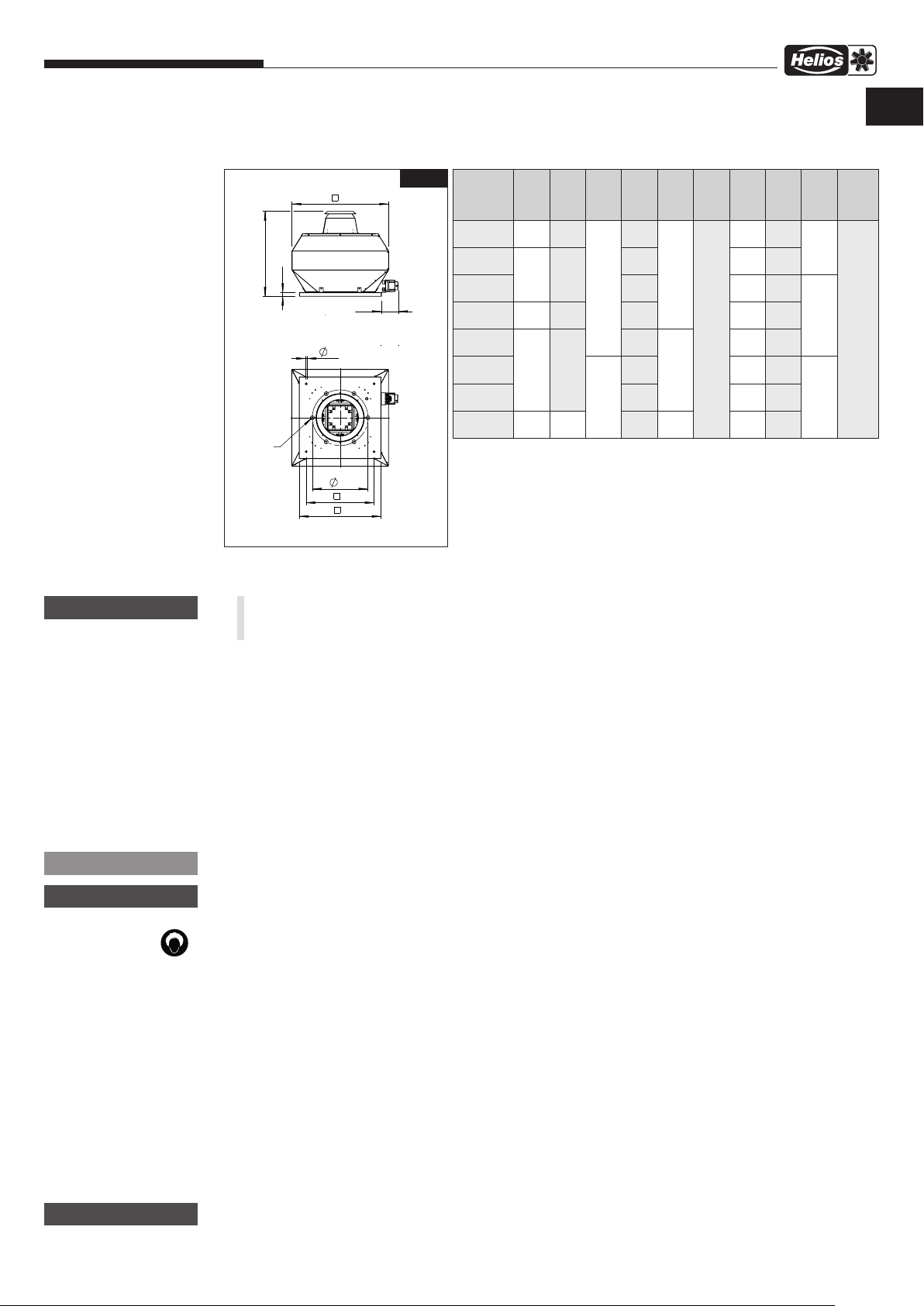
Notice de montage et d’utilisation
H
D
E
F
H
C
3.2 Mesures
Série VDD.. 315-630
VD.. – Tourelles de toitures
FR
AVERTISSEMENT
m
Fig.1
D
E
F
Y
LK
B
A
Dimensions en mm
3.3 Raccordement électrique
m AVERTISSEMENT
Avant tout travail de maintenance ou d’installation, ou avant l’ouverture du boîtier de raccordement, mettre
tous les pôles de l’appareil
hors tension et empêcher tout redémarrage accidentel !
– Le raccordement électrique lors de la mise en service ne doit être effectué que par électricien qualifié selon les don-
nées de la boîte à bornes / interrupteur de proximité et selon le plan de raccordement.
– Les normes en vigueur, les dispositions de sécurité et les conditions techniques de raccordement sont à respecter
impérativement !
– Forme de réseau, tension et fréquence doivent correspondre aux données techniques indiquées sur la plaque signa-
létique du modèle.
Les moteurs sont câblés systématiquement pour une rotation droite (voir flèche d'indication du sens de rotation).
– Le câble de mise à la terre, y compris les raccords d’équipotentialité sont obligatoirement à installer !
– Vérifier l'étanchéité du câble et la bonne fixation des fils dans les bornes.
– L’introduction des câbles doit être correctement effectuée ! Le raccordement des câbles à la boîte à bornes/inter-
rupteur de proximité (IP 65) doit permettre de compenser les éventuelles vibrations du ventilateur.
Type
VD 315
VD 355
VD 400
VD 450 730 590
VD 500
VD 560
VD 630
VD 710
y
y
A
580 450
645 535
925 750
1260 1050
B Ø C
12
14
E F H Ø LK Y
y
D
605
740 640 395
30
765 690 438
860 760 487
965
1070 1015 605
40
1155 1070 674
1365
65
136
570 356
790 541
1130 751
8 x
M8
6 x
M8
8 x
M10
Racc.
élec.
X
Interrupteur de proximité
REMARQUE
m
nmr
m
+
ATTENTION
ATTENTION
l
Les accessoires d’installation pour la boîte à bornes/interrupteur de proximité doivent répondre à l’indice de protec
tion IP65.
Ne jamais poser les câbles sur des arêtes tranchantes !
3.4 Mise en service
m AVERTISSEMENT
Les parties rotatives de la turbine peuvent pincer vos doigts.
Empêcher tout contact accidentel avant la mise en service !
Les contrôles suivants sont à effectuer ou à vérifier avant la première mise en service :
– Vérifier l'utilisation conforme du ventilateur
– Vérifier températures admissibles des fluides.
– Comparer la tension de réseau avec celle indiquée sur la plaque signalétique.
– Vérifier la conformité de l’installation électrique de l’ALB.
– Contrôler le raccordement du câble de protection.
– Retirer les résidus de montage du ventilateur ou des gaines.
– Vérifier que toutes les parties sont bien fixées, en particulier les vis, les écrous et la grille de protection. Ne pas des-
serrer les vis ! Il ne doit pas y avoir de pièces non fixées dans le ventilateur.
– Vérifier la stabilité du ventilateur ! Veiller à ce que le boîtier à bornes/la trappe de révision et l’unité moto-turbine soient
facilement accessibles.
– S’assurer que les zones de soufflage et d’aspiration ne sont pas accessibles aux personnes non autorisées.
– Vérifier l’étanchéité de toutes les connexions (si nécessaire).
– Vérifier la rotation libre et le sens de rotation de la turbine via démarrages de courtes durées ; porter des lunettes
de protection lors de la vérification.
5

Notice de montage et d’utilisation
3.5 Fonctionnement
m
AVERTISSEMENT
n
Pour la garantie d'un bon fonctionnement, les points suivants sont à effectuer régulièrement :
– Vérifier la libre rotation des pales
– Courant absorbé dans la plage indiquée sur la plaque signalétique.
– Pas de vibrations ni de bruits anormaux.
– Pas de dépôt de poussière ou de saleté dans le boîtier ni sur le moteur ou la turbine
– Si vous rencontrez un problème en vérifiant les points ci-dessus, procéder à un entretien selon les consignes du
chapitre 4.
VD.. – Tourelles de toitures
– Comparer le courant absorbé avec celui indiqué sur la plaque signalétique.
– Tester le bon fonctionnement du dispositif de protection moteur. Vérifier les vibrations et les bruits lors d’une mise
en marche test. Lors de fortes vibrations et/ou de bruits, le ventilateur sort de sa plage de fonctionnement. Dans ce
cas, contacter impérativement le fabricant !
– Vérifier l’étanchéité du câble dans le boîtier à bornes et la bonne fixation des fils dans les bornes.
– Ne pas utiliser le ventilateur en dehors des courbes de performances (voir catalogue/site Internet). Le ventilateur doit
atteindre son point de fonctionnement.
– Afin de garantir un refroidissement du moteur, prévoir une vitesse/tension min. via un découpage de phases
lors du paramétrage de la tension. Celle-ci dépend également de la résistance, de la pression, du vent, etc.
Elle doit être choisi de façon à garantir un démarrage et fonctionnement sécurisé et stable.
AVERTISSEMENT
m
Risque de brûlure !
Des températures élevées au niveau du boîtier du ventilateur peuvent provoquer de graves brûlures.
Porter des gants de protection appropriés !
CHAPITRE 4
MAINTENANCE ET
ENTRETIEN
m
AVERTISSEMENT
nmr
4.0 Entretien et maintenance
AVERTISSEMENT
m
Avant tous travaux de maintenance ou d’installation, ou avant l’ouverture du boîtier de raccordement, mettre
tous les pôles de l’appareil hors tension et empêcher tout redémarrage accidentel
AVERTISSEMENT
m
Risque de brûlure !
Des températures élevées au niveau du boîtier du ventilateur peuvent provoquer de graves brûlures.
Porter des gants de protection appropriés !
– Les appareils ne nécessitent pas, en principe, de maintenance Néanmoins, tous les travaux de maintenance doivent
être effectués par le personnel autorisé selon le chapitre 1.6 !
– Empêcher tout dépôt de poussière, saleté, graisse, etc. sur la turbine, le moteur, la grille de protection et surtout
entre la virole et la turbine : les dépôts peuvent alourdir les pales, entraîner une surchauffe du moteur ou bloquer le
ventilateur. Si le cas se présente, voir section 4.1 pour le nettoyage.
– Si l’appareil est soumis à une utilisation intensive sur le plan technique, il est nécessaire de procéder à une mainte-
nance aussi régulière que l’exige cette utilisation. Après une longue période d’inactivité, effectuer une opération de
maintenance avant tout redémarrage.
– Points de contrôle :
• la bonne fixation du ventilateur
• éliminer les dépôts de saleté
• l'absence de dommage
• Un bon vissage, surtout au niveau de la turbine Ne pas desserrer les vis !
• Vérifier le revêtement de la surface du boîtier/de la turbine (si rouille, peinture endommagée, etc.).
• Libre rotation de la turbine.
• Vérifier l'absence de bruit de roulements.
• Observer tout bruit ou vibration éventuel
• Comparer la puissance absorbée et celle indiquée sur la plaque signalétique
• · Vérifier le bon fonctionnement des dispositifs de sécurité (protection moteur, par ex.)
• Dommages au niveau de la trappe de visite
Les roulements à billes utilisés ne nécessitent aucun entretien dans des conditions normales d'utilisation et sont
conçus pour une durée de vie de 20 000 heures. Pour un entretien préventif, les roulements à billes doivent être
remplacés au plus tard après 5 ans, quelles que soient les heures de service,
en raison du vieillissement de la graisse.
m
AVERTISSEMENT
nm
4.1 Nettoyage
M
En cas d’isolation incorrecte, vous risquez de vous électrocuter !
Avant de commencer le nettoyage du ventilateur, mettre tous les pôles de l’appareil hors tension et empê
cher tout redémarrage accidentel !
AVERTISSEMENT
– Un démontage de l'appareil ou de certaines pièces peut être nécessaire pour le nettoyage.
Celui-ci doit être effectué par du personnel qualifié, tel qu'indiqué au chapitre 1.6 !
– Nettoyer la zone de soufflage, la turbine, les supports et le moteur du ventilateu
– N’utiliser aucun nettoyant agressif ni aucun solvant !
– L’utilisation d’un nettoyeur à haute pression ou des projections d’eau n’est pas permise !
6

Notice de montage et d’utilisation
VD.. – Tourelles de toitures
DE
m
ATTENTION
l m p r n
Dysfonctionnement Causes Solutions
Le ventilateur ne dé-
marre pas
La sécurité se déclenche
L'interrupteur de protection se déclenche
La protection moteur se
déclenche
Vibrations Encrassement Nettoyer
4.2 Indications des origines de dysfonctionnements
Les consignes de sécurité au point 1.2 du chapitre 1 sont à respecter !
La réparation des défauts doit uniquement être effectués que par du personnel qualifié, voir paragraphe 1.6 !
Aucune tension, défaut de phase vérifier la tension réseau
Turbine bloquée débloquer la pale, nettoyer
Moteur bloqué Vérifier le moteur, le remplacer si nécessaire
Court-circuit du moteur Remplacer le moteur
Câbles/raccordements défectueux Remplacer les pièces, le moteur si nécessaire
Mauvais raccordement Vérifier le raccordement, le remplacer
isolation moteur défectueuse Remplacer le moteur
Isolation du câblage défectueuse Remplacer les raccordements
Roulements durs Remplacer les roulements
Frottement de la turbine Nettoyer, remplacer la turbine le cas échéant
Mauvais point de fonctionnement Vérifier la compatibilité du ventilateur,
Moteur encrassé Nettoyer
Roulements défectueux Remplacer les roulements
Mauvais point de fonctionnement Vérifier la compatibilité du ventilateur,
Résonances Vérifier la fixation/l'améliorer, installer des amortisseurs
remplacer la turbine si nécessaire
vérifier le bon écoulement des flux/dégager
vérifier le bon écoulement des flux/dégager
mauvais sens de rotation, Vérifier/modifier le raccordement
La turbine est déséquilibrée Effectuer un équilibrage par une société spécialisée
Bruits anormaux Mauvais point de fonctionnement Vérifier la compatibilité du ventilateur,
Turbine abrasive Nettoyer, remplacer si nécessaire
Roulements défectueux Remplacer les roulements
Dommages mécaniques Procéder à la maintenance
mauvais sens de rotation, Vérifier/modifier le raccordement
Courant nominal trop
élevé
Le ventilateur n’atteint
pas les performances/
vitesses indiquées
4.3 Pièce de rechange
Utiliser exclusivement des pièces de rechange Helios d’origine. Toutes les réparations doivent être confiées à des personnes / entreprises spécialisées et habilitées.
Mauvais point de fonctionnement Vérifier la compatibilité du ventilateur,
Turbine abrasive Nettoyer, remplacer si nécessaire
Roulements défectueux Remplacer les roulements
Mauvais point de fonctionnement Vérifier la compatibilité du ventilateur, vérifier le bon
mauvaise tension Vérifier/modifier le raccordement
Roulements défectueux Remplacer les roulements
Encrassement Nettoyer
Mauvais renouvellement d’air Agrandir les entrées de renouvellement
mauvais sens de rotation, Vérifier/modifier le raccordement
vérifier le bon écoulement des flux/dégager
vérifier le bon écoulement des flux/dégager
écoulement des flux/dégager
m
AVERTISSEMENT
nm
4.4 Mise hors service et mise au rebut
Lors du démontage, des parties restent sous tension, ce qui peut entraîner une électrocution en cas de contact.
Avant le démontage, mettre tous les pôles du ventilateur hors tension et empêcher tout redémarrage accidentel !
– Lors du recyclage du moteur, respecter les consignes de la notice d’entretien du moteur électrique
– Les composants du ventilateurs respectent les lois et normes en vigueur
AVERTISSEMENT
m
Veiller à bien respecter les règles de sécurité afin d’éviter tout accident !
– Les manipulations électriques ne doivent être effectuées que par des électriciens qualifiés
– Veiller à ce que les raccordements soient hors tension
– Utiliser des appareils de levages et des dispositifs de fixation adéquats lors du démontage du ventilateur
7

Notice de montage et d’utilisation
VD.. – Tourelles de toitures
CHAPITRE 5
DONNÉES TECHNIQUES
5.0 Données techniques
Les données techniques des produits figurent sur la plaque signalétique. Exemple de contenu de plaque signalétique.
q
HELIOS VENTILATOREN GmbH + Co KG
Lupfenstraße 8, 78056 Villingen-Schwenningen, Germany
e
Type : VDD 630/6 T120
t
400/690 V D/Y
980 1/min
Einsatz und Betrieb nur gemäß Instruktions-Nr.
Operation only according to instruction no.
Utilisation uniquement selon instruction no.
Légende de la plaque signalétique du ventilateur :
q Adresse du fabricant y Intensité nominale
w Marquage du ventilateur : U u Puissance nominale absorbée
CE = Symbole CE i Température ambiante / du flux d’air max. en fonction nominale
e Version : Vitesse nominale
VDD = Désignation du modèle ; triphasé Protection / Classe d’isolation du moteur / Condensateur
630 = Taille Poids
/6 = pôles
r Référence / Code de production
t Tension / Fréquence
50 Hz
IP55
r
Réf. : 7456 001
y
10 A
Iso.cl. F
u
27 199
4,0 kW
w
PC 08510
i
TN 120 °C
125 kg
Fig.3
CHAPITRE 6
SCHÉMA DE
RACCORDEMENT
SS-1296
VDD 315/4 T120
VDD 355/4 T120
VDD 400/4 T120
VDD 400/6 T120
VDD 450/4 T120
VDD 450/6 T120
VDD 500/6 T120
VDD 560/6 T120
6.0 Schémas de raccordement
2
1
3~ Motor
M
3
10
9
L3
5
12
11
TK
2
1
4
3
6
5
L1
8
7
L2
mit TB (TK)
6
14
13
TK
PE
RS 3+1+2
85499 058 SS-1296 23.02.18
8

Notice de montage et d’utilisation
SS-1130
VDD 500/4 T120
VDD 560/4 T120
VDD 630/6 T120
VDD 710/6 T120
VD.. – Tourelles de toitures
TB/TP
TB/TP
W2
V2
U2
W1
V1
3~ Motor
mit TB/TP (TK/KL)
U1
FR
Farbcode nach IEC 757
PE
TP
TB/
TB/
8
7
20
19
TB/TP
TP
W2
6
16
18
15
17
W2
TB/TP
5
V2
14
13
V2
4
U2
12
11
U2
3
W1
10
9
W1
2
V1
8
7
V1
1
U1
6
5
U1
U1 BN-br-braun-brown
V1 BU-bl-blau-blue
W1 BK-sw-schwarz-black
U2 RD-rt- rot-red
V2 GY-gr-grau-grey
4
2
3
1
W2 OG-or-orange-orange
TB/TP WH-ws-weiß-white
PE YE-GN-ge-gn-gelb-grün
-yellow-green
Schalter
85419 001 SS-1130 14.09.16
9

Als Referenz am Gerät griffbereit aufbewahren! Druckschrift-Nr.
Please keep this manual for reference with the unit! Print no.
Garder cette notice à proximité de l’appareil ! N° de réf. 27 199-001/V01/0718
Service und Information
D HELIOS Ventilatoren GmbH + Co KG · Lupfenstraße 8 · 78056 VS-Schwenningen F HELIOS Ventilateurs · Le Carré des Aviateurs · 157 av. Charles Floquet · 93155 Le Blanc Mesnil Cedex
CH HELIOS Ventilatoren AG · Tannstrasse 4 · 8112 Otelfingen GB HELIOS Ventilation Systems Ltd. · 5 Crown Gate · Wyncolls Road · Severalls Industrial Park ·
A HELIOS Ventilatoren · Postfach 854 · Siemensstraße 15 · 6023 Innsbruck Colchester · Essex · CO4 9HZ
www.heliosventilatoren.de
 Loading...