

Page 1
Helios Ventilatoren
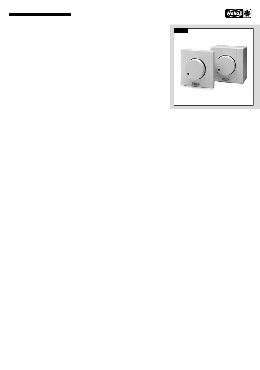
Drehzahl-Potentiometer PU/A ..
Potentiometer PU/A ...
Unter- oder Aufputz als Drehzahlsteller mit Zusatzfunktion
– PU/A 10/24, Potentiometer mit den Zusatzfunktionen Schalter und LED
MONTAGE- UND BETRIEBSVORSCHRIFT NR. 82 525
1.0 Wichtige Informationen
Zur Sicherstellung einer einwandfreien
Funktion und zur eigenen Sicherheit
sind alle nachstehenden Vorschriften
genau durchzulesen und zu beachten.
2.0 Garantieansprüche –
Haftungsausschluss
Wenn die nachfolgenden Ausführungen nicht beachtet werden, entfällt unsere Gewährleistung. Gleiches gilt für
Haftungsansprüche an den Hersteller.
Der Gebrauch von Zubehörteilen, die
nicht von Helios empfohlen oder angeboten werden, ist nicht statthaft.
Even tuell auftretende Schäden unterliegen nicht der Gewährleistung.
3.0 Lieferprogramm
Drehzahl-Potentiometer
– LED Versorgung 10 V
Type PU 10 Best.-Nr. 1734
Für Unterputz-Installation.
Type PA 10 Best.-Nr. 1735
Für Aufputz-Installation.
Drehzahl-Potentiometer
– LED Versorgung 24 V
Type PU 24 Best.-Nr. 1736
Für Unterputz-Installation.
Type PA 24 Best.-Nr. 1737
Für Aufputz-Installation.
4.0 Einsatzbereich
Die Drehzahl-Potentiometer PU/A ..
sind zur direkten Steuerung bzw. Soll
wertvorgabe von z.B. EC-Ventilatoren
mit Potentiometer Eingang vorgesehen.
Die Typen sind zusätzlich mit einem
Freigabe-Schalter und LED-Anzeige
für den Betriebszustand ausgerüstet
(Abhängig von der Ausstattung der
Ventilatortype).
5.0 Elektrischer Anschluss
Vor allen Wartungs- und Instal-
m
lationsarbeiten ist das Gerät allpolig
vom Netz zu trennen!
Der elektr. Anschluss darf nur von
einer autorisierten Elektrofachkraft
durch ge führt werden.
Die einschlä gi gen Sicher heits vorschriften, Normen (VDE 0100 und VDE 0700
sowie die TAB‘s der EVU‘s und UVV)
sind einzuhalten. Eben so ist die Mon ta ge- und Betriebsvor schrift des Ventilators zu beachten.
6.0 Steuerung mit Potentiometer
Das Potentiometer PU/A .. wird direkt
an den Potentiometer Eingang der
Ventilatorsteuerung angeschlossen.
Diese hat hierfür eine Potentiometerversorgung von z.B. 10 V DC und
einen Sollwerteingang von 0-10 V DC.
7.0 Mindestspannung
Im PU/A .. ist ein zweites Potentiometer fest integriert. Die Mindestspannung kann von ca. 1,3 V bis 6,7 V
eingestellt werden (mit Potiversorgung
10 V). Die Mindestspannung von 1,3 V
kann nicht unterschritten werden. Damit ist eine Untergrenze für flüssigen
Motoranlauf fest voreingestellt.
8.0 Freigabe Schalter
Der Frontdrehknopf für das Potentiometer ist gleichzeitig ein Schalter. Hat
die Ventilatorsteuerung einen Freigabeeingang (z.B. 24 V DC), kann dieser
über den Freigabeschalter betätigt
werden.
-
9.0 Steuerleitung
Es wird eine Steuerleitung mit 7 x
0,5 mm² empfohlen (Aderanzahl, je
nach Einsatzfall, siehe entsprechende
Schaltpläne zum Ventilator). Um Einstreuungen zu vermeiden, muss auf
ausreichenden Abstand zu Netz- und
Motorleitungen geachtet werden.
Maximale Länge 30 m, ab 20 m
Abb.1
müssen diese geschirmt sein. Bei
Verwendung einer geschirmten Leitung, muss der Schirm einseitig an
der Erde/Schutzleiter am Ventilator
verbunden werden.
10.0 Kleinspannung / Potential
Der PU/A ist für den Einsatzbereich
< 50 V ausgelegt. Bei der Installation
muss darauf geachtet werden, dass
der Kleinspannungsteil von der Netz
Installation (230 V/400 V) sicher getrennt ist.
Der Freigabeschalter ist von Potentiometer und LED galvanisch getrennt
(auf Kleinspannungsniveau). Potentiometer und LED sind über GND/verbunden.
11.0 Leuchtring mit LED
Die Farbe im Leuchtring signalisiert
den Betriebszustand des Ventilators.
Zum Betreiben der LED’s, muss die
Ventilatorsteuerung eine Versorgung
von 24 V DC oder 10 V DC mit einem
Mindeststrom von 6 mA, zu Verfügung
stellen.
In der Regel wird beim Ventilator ein
Relais den Betriebszustand des Ventilators anzeigen. Mit entsprechender
Versorgungsspannung kann über das
Relais, die LED’s angesteuert werden.
Durch die integrierte Umschalt-Logik
im PU/A .. kann auch mit nur einem
Schließer-Kontakt als Betriebsanzeige des Ventilators, eine Anzeigeumschaltung von rot auf grün realisiert
1
Page 2
Helios Ventilatoren
Drehzahl-Potentiometer PU/A ..
werden.
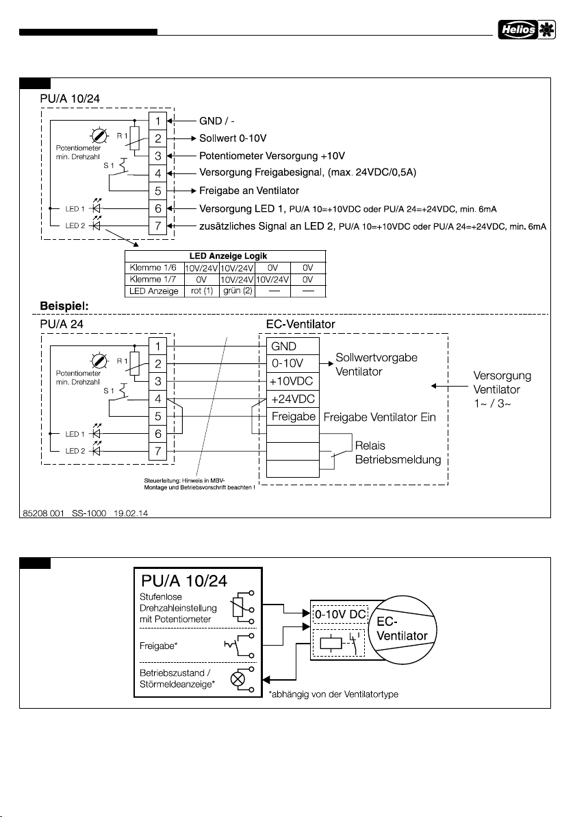
Mit der Basisversorgung auf Klemme
6 leuchtet die rote LED. Bei zusätzlicher Versorgung auf Klemme 7 wird
von rot auf grün umgeschaltet.
Hierzu bitte die LED Anzeige Logik
im Schaltplan SS-1000 (siehe Seite
3) beachten.
Zubehör, Schalt- und
12.0
Steuerelemente
Der Gebrauch von Zubehörteilen, die nicht von Helios empfohlen oder angeboten werden, ist
nicht statthaft.
Even tuell auftretende Schäden unterliegen nicht der Gewährleistung.
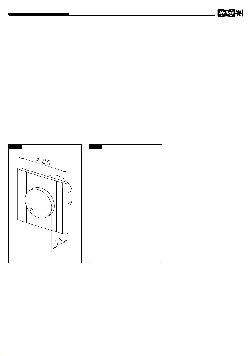
Einbaumaße Unterputz
13.0 Technische Daten
Kunststoffgehäuse, weiß,
Schutzart IP 40
Potentiometer:
ca. 7,9 - 16,5 kOhm
(je nach Stellung des min. Potis)
Max. 24 V DC
Schalter:
Max. 24 V DC / 0,5 A
LED:
PU/A 10
Versorgung 10 V DC min. 6 mA
PU/A 24
Versorgung 24 V DC min. 6 mA
Einbaumaße Aufputz
Abb.3Abb.2
Anschlussklemmen:
eindrähtig 0,5 - 1,5 mm²
mit Aderendhülse 0,25 - 1,0 mm²
Abisolierlänge 9 - 10 mm
Zulässige Umgebungstemperatur:
0 - 40 °C
Abmessungen:
B 80 x H 80 x T65
Schaltplan Nr.:
SS-1000
Maße in mm
Dimensions in mm
Dimensions en mm
Maße in mm
Dimensions in mm
Dimensions en mm
2
Page 3
Helios Ventilatoren
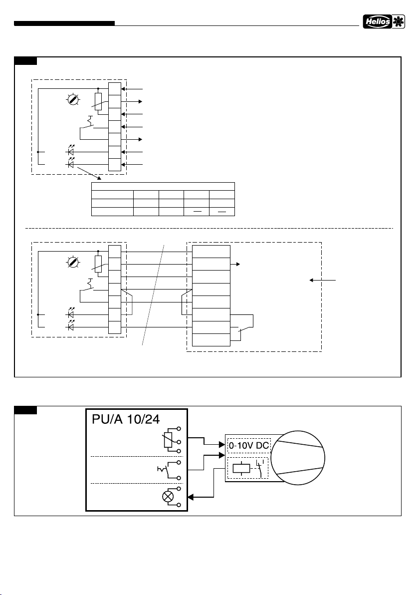
14.0 Schaltplan SS-1000
Abb.4
Drehzahl-Potentiometer PU/A ..
15.0 Prinzipschema
Abb.5
Î
3
Page 4

Als Referenz am Gerät griffbereit aufbewahren! Druckschrift-Nr. 82 525/02.14
Service / Information
D HELIOS Ventilatoren GmbH & Co · Lupfenstraße 8 · 78056 VS-Schwenningen
A HELIOS Ventilatoren · Postfach 854 · Siemensstraße 15 · 6023 Innsbruck
F HELIOS Ventilateurs · Le Carré des Aviateurs · 157 av. Charles Floquet · 93155 Le Blanc Mesnil Cedex
CH HELIOS Ventilatoren AG · Steinackerstraße 36 · 8902 Urdorf /Zürich
GB HELIOS Ventilation Systems Ltd. · 5 Crown Gate · Wyncolls Road · Severalls Industrial Park · Colchester · Essex · CO4 9HZ
www.heliosventilatoren.de
Page 5
Helios Ventilatoren
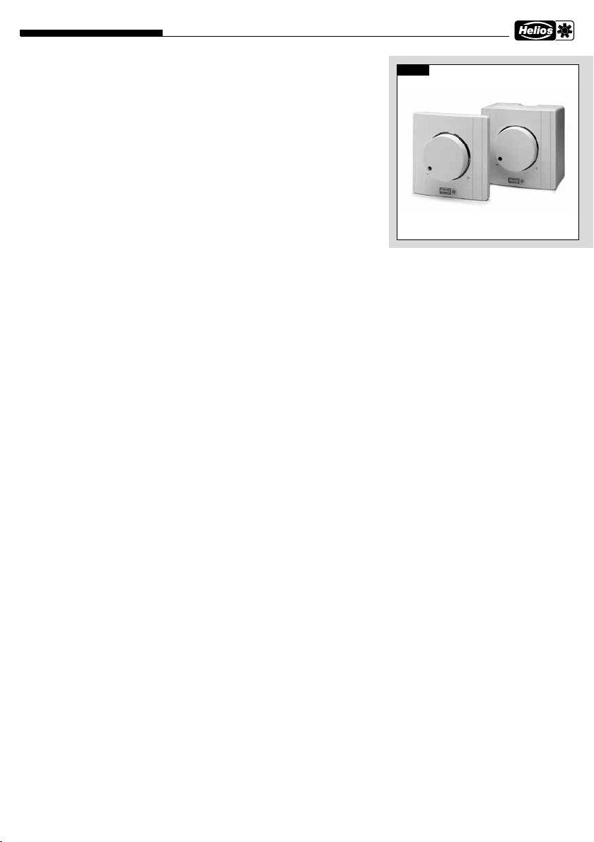
Speed Potentiometer PU/A ..
Potentiometer PU/A ...
Flush or surface-mounted as speed controller with additional function
– PU/A 10/24, potentiometer with additional functions of switch and LED
INSTALLATION AND OPERATING INSTRUCTIONS NO. 82 525
1.0 Important information
In order to ensure complete and effective operation and for your own
safety, all of the following instructions
should be read carefully and observed.
2.0 Warranty claims –
Exclusion of liability
If the instructions in this documentation are not observed, all warranty
claims shall be excluded. This also
applies to any liability claims extended
to the manufacturer. The use of accessories which are not recommended, offered or approved by HELIOS
is not permitted. Any potential damage is not covered by warranty.
3.0 Delivery programme
Speed Potentiometer
– LED supply 10 V
Type PU 10 Ref. no. 1734
for flush-mounting.
Type PA 10 Ref. no. 1735
for surface-mounting.
Speed Potentiometer
– LED supply 24 V
Type PU 24 Ref. no. 1736
for flush-mounting.
Type PA 24 Ref. no. 1737
for surface-mounting.
4.0 Application
The Speed Potentiometer PU/A .. are
equipped with a potentiometer input for
the direct control or set value specifica
tion of e.g. EC fans.
The models are also equipped with a
release switch and LED display for the
operating status (depending on the fan
type features).
5.0 Electrical connection
The unit must be fully isolated
m
from the mains power supply before
maintenance and installation work!
Electrical connection may only be
carried out by a qualified person.
The relevant standards, safety regula
tions (such as VDE 0100, VDE 0530 and
VDE 0700 and the technical connection
conditions of the local electricity supply
companies) must be observed. The fan
installation and operating instructions
must also be observed.
6.0 Controlling the potentiometer
The Potentiometer PU/A .. is connected directly to the potentiometer input
on the fan controller. This has a potentiometer power supply of e.g. 10 V
DC and a set value input of 0-10 V DC
for this purpose.
7.0 Minimum voltage
A second potentiometer is integrated
in the PU/A .. The minimum voltage
can be set from 1.3 V to 6.7 V (with
poti supply 10 V). This value cannot be
less than the minimum voltage of 1.3
V. Thus, there is a lower limit is pre-set
for smooth motor startups.
8.0 Release switch
The front rotary button for the potentiometer is also a switch. If the fan
controller has a release input (e.g.
24 V DC), it can be activated by the
release switch.
9.0 Control line
A 7 x 0.5 mm² control line is recom-
-
mended (number of wires depending
on application, see corresponding fan
wiring diagrams). In order to prevent
interference, there must be sufficient
distance between the power supply
and motor lines.
Maximum length 30 m, and must
be shielded over 20 m. When using
shielded lines, the shield must be
Fig.1
-
unilaterally connected to the ground
wire/protective conductor on the fan.
10.0 Low-voltage / potential
The PU/A is designed for the range of
application < 50 V. When installing, it
must be ensured that the low-voltage
part of the mains installation (230
V/400 V) is safely isolated.
The release switch is galvanically isolated from the potentiometer and LED
(at low-voltage level). The potentiometer and LED are connected via GND/-.
11.0 Light ring with LED
The colour of the light ring indicates
the operating status of the fan. In order to activate the LED’s, the fan controller must provide a power supply of
24 V DC or 10 V DC with a minimum
current of 6 mA.
A relay will normally display the operating status of the fan. The LED’s can
be controlled with the corresponding
supply voltage via the relay.
A display switch from red to green
can be achieved as the operating status of the fan through the integrated
switching logic in the PU/A .. with just
one normally open contact.
The red LED lights up with a basic
supply to terminal 6. Red will switch
to green with additional power supply
to terminal 7.
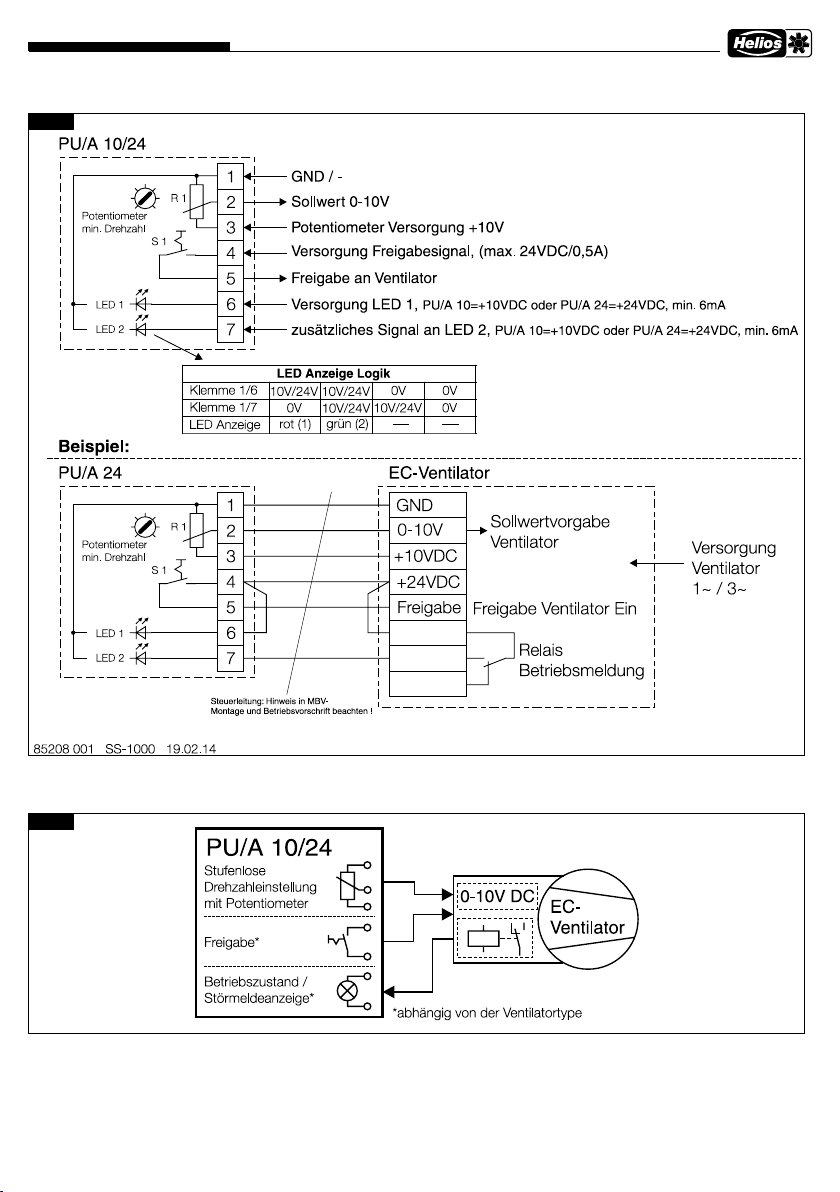
In this respect, lease not the LED display logic in wiring diagram SS-1000
(see page 3).
1
Page 6
Helios Ventilatoren
Speed Potentiometer PU/A ..
12.0
Accessories, switch and
control elements
The use of accessories which are not
recommended, offered or approved by
HELIOS is not permitted.
Any potential damage is not covered
by warranty.
13.0 Technical data
Plastic casing, white,
Protection class IP 40
Potentiometer:
approx. 7.9 - 16.5 kOhm
(depending on setting of min. Potis)
Max. 24 V DC
Switch:
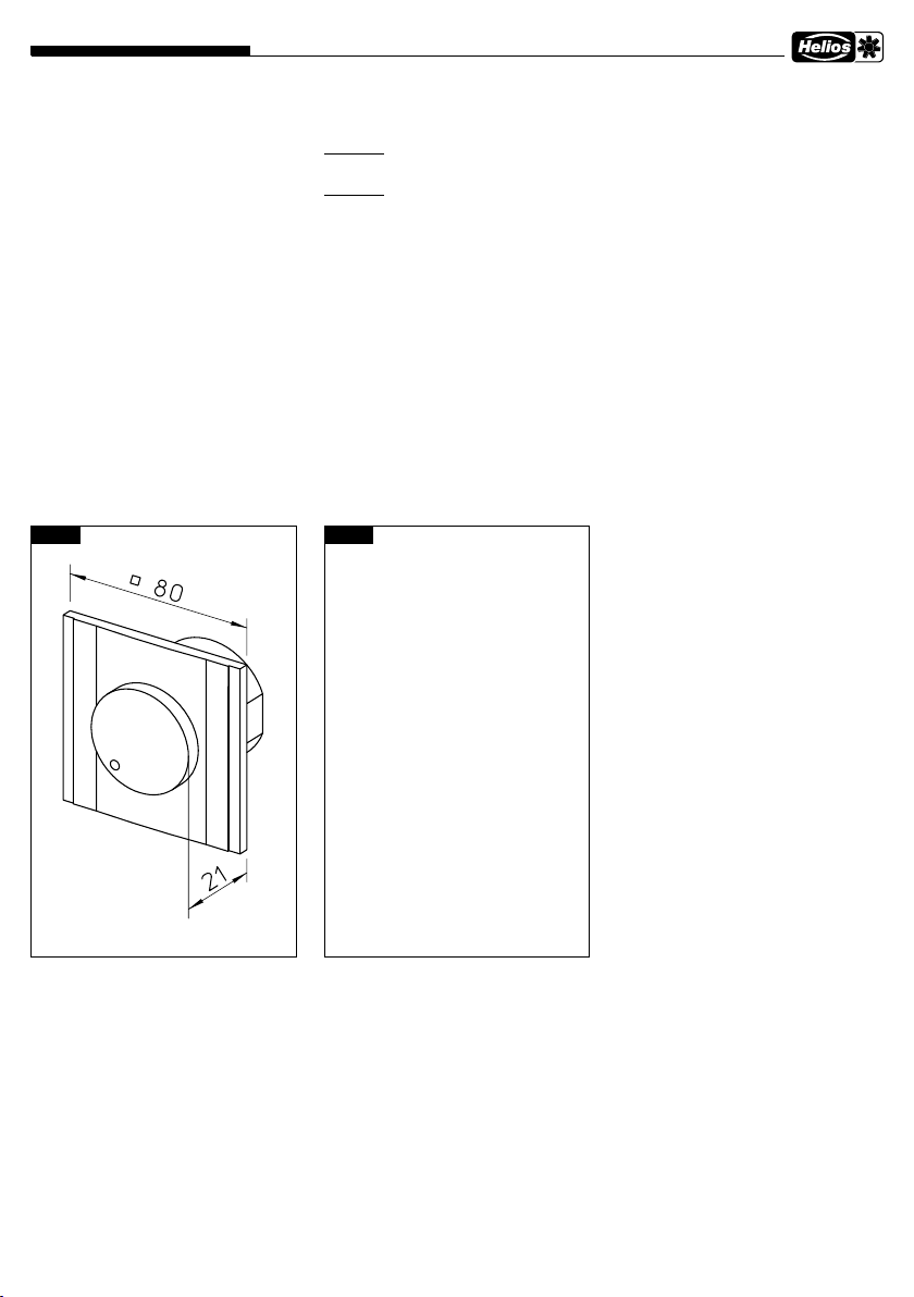
Installation dim. flush-mounting
Max. 24 V DC / 0.5 A
LED:
PU/A 10
Power supply 10 V DC min. 6 mA
PU/A 24
Power supply 24 V DC min. 6 mA
Connection terminals:
single-wire 0.5 - 1.5 mm²
with wire-end ferrule 0.25 - 1.0 mm²
Stripping length 9 - 10 mm
Permissible ambient temperature:
Installation dim. surface-mounting
Fig.3Fig.2
0 - 40 °C
Dimensions:
W 80 x H 80 x D 65
Wiring diagram no.:
SS-1000
Dimensions in mm
Dimensions in mm
2
Page 7
Helios Ventilatoren
14.0 Wiring diagram SS-1000
Fig.4
Speed Potentiometer PU/A ..
15.0 Basic circuit diagram
Fig.5
Î
3
Page 8

Please keep this manual for reference with the unit! Print no. 82 525/02.14
Service / Information
D HELIOS Ventilatoren GmbH & Co · Lupfenstraße 8 · 78056 VS-Schwenningen
A HELIOS Ventilatoren · Postfach 854 · Siemensstraße 15 · 6023 Innsbruck
F HELIOS Ventilateurs · Le Carré des Aviateurs · 157 av. Charles Floquet · 93155 Le Blanc Mesnil Cedex
CH HELIOS Ventilatoren AG · Steinackerstraße 36 · 8902 Urdorf /Zürich
GB HELIOS Ventilation Systems Ltd. · 5 Crown Gate · Wyncolls Road · Severalls Industrial Park · Colchester · Essex · CO4 9HZ
www.heliosventilatoren.de
Page 9
Helios Ventilateurs
Potentiomètre de vitesse PU/A ..
Potentiomètre PU/A ...
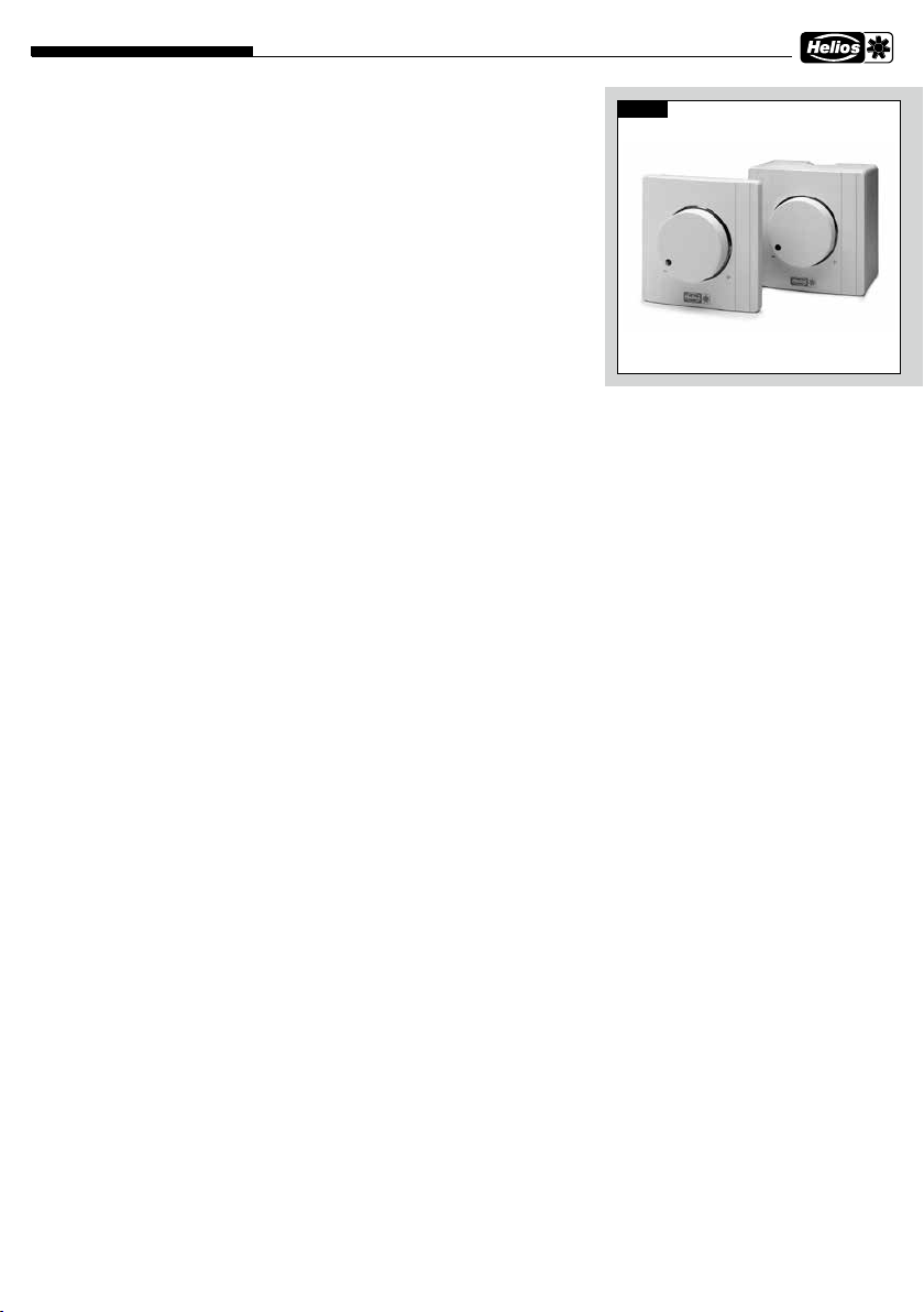
Variateur encastrable ou apparent avec fonction supp.
– PU/A 10/24, potentiomètre avec interrupteur avec fonctions supp. et LED
MONTAGE- UND BETRIEBSVORSCHRIFT NR. 82 525
1.0 Informations importantes
Il est important de bien lire et suivre
l’ensemble des consignes suivantes
pour le bon fonctionnement de
l’appareil et pour la sécurité des
utilisateurs.
2.0 Demande de garantie –
Réserves du constructeur
Si les consignes suivantes ne sont
pas respectées, la garentie s’annule. Même chose pour les réserves
construteur. L’utilisation d’accessoires non proposés ou non conseillés par Helios n’est pas permise.
Les dégâts éventuels causés par
une utilisation non conforme ne
sont pas pris en charge.
3.0 Programme de livraison
Potentiomètre
– LED alimentation 10 V
Type PU 10 Réf. n°1734
Pour une installation encastrée.
Type PA 10 Réf. n°1735
Pour une installation apparente.
Potentiomètre
– LED alimentation 24 V
Type PU 24 Réf. n°1736
Pour une installation encastrée.
Type PA 24 Réf. n°1737
Pour une installation apparente.
4.0 Plage d’utilisation
Les potentiomètres PU/A .. sont prévus pour une commande directe ou
par entrée de valeurs de consigne du
ventilateur EC par ex. avec entrée de
potentiomètre.
Les modèles sont équipés d’un commutateur d’activation et d’un affichage LED pour le mode de fonctionnement (en fonction de l’équipement
du ventilateur).
5.0 Raccordement électrique
Avant tous travaux de mainte-
m
nance ou d’installation, veiller à ce
que l’appareil soit hors tension !
Le raccordement électrique ne
peut être effectué que par un électricien qualifié.
Respecter les normes et les textes de
loi en vigueur (VDE 0100 et VDE 0700
ainsi que les TAB des EVU et UVV).
Respecter également les consignes
de la notice du ventilateur.
6.0 Régulation avec potentiomètre
Le potentiomètre PU/A .. est à
raccorder directement sur l’entrée du
potentiomètre. Celui-ci doit posséder
une alimentation de par ex. 10 V DC
pour le potentiomètre et une consigne
d’entrée de 0-10 V DC..
7.0 Tension minimale
Un deuxième potentiomètre est
intégré dans le PU/A .. La tension
minimale peut être réglée env. de
1,3 V à 6,7 V (avec alimentation 10 V
du potentiomètre). La tension minimale ne peut pas être inférieure à 1,3 V.
Une limite inférieure pour démarrage
liquide du moteur est ainsi prédéfinie.
8.0 Commutateur d’activation
Le bouton rotatif avant du potentiomètre fait également office de commutateur.
teur a une entrée d’activation (par ex.
24 V CC), celle-ci peut être commandée
via le commutateur d’activation.
9.0 Régulation
Un câble de commande de 7x0,5 m²
est recommandé (nombre de conducteurs, en fonction du cas d’utilisation, voir les schémas de câblage
correspondants du ventilateur). Afin
d’éviter les interférences, il convient
de respecter une distance suffisante
par rapport aux câbles secteur et du
moteur.
Si la commande de ventila-
Fig. 1
Longueur maximale 30 m, à partir
de 20 m, ils doivent être blindés. En
cas d’utilisation d’un câble blindé, le
blindage doit être relié d’un côté au
conducteur de terre/protection du
ventilateur.
10.0 Petite tension / Potentiel
Le PU/A est conçu pour une plage
d’utilisation <50 V. Lors de l’installation, il faut veiller à ce que la partie
basse tension soit isolée en toute
sécurité de l’installation électrique
(230 V/400 V).
Le commutateur d’activation est isolé
galvaniquement du potentiomètre et
des LED (au niveau basse tension). Le
potentiomètre et les LED sont reliés
via GND/-.
11.0 Bague lumineuse avec LED
La couleur de la bague lumineuse
signale l’état de fonctionnement du
ventilateur. Pour actionner les LED, la
commande du ventilateur doit mettre
à disposition une alimentation de 24 V
CC ou 10 V CC avec un courant minimal de 6 mA.
En règle générale, c’est un relais qui
indiquera l’état de fonctionnement du
ventilateur sur ce dernier. Les LED
peuvent être commandées via le relais
avec la tension d’alimentation correspondante. Grâce à la logique de
commutation intégrée dans le PU/A..,
il est également possible de changer l’affichage de rouge à vert avec
1
Page 10
Helios Ventilateurs
Potentiomètre de vitesse PU/A ..
seulement un contact de fermeture
comme indication de fonctionnement
du ventilateur.
La LED rouge s’allume avec l’alimentation de base sur la borne 6. En cas
d’alimentation supplémentaire sur la
borne 7, le rouge passe au vert.
La description de l’affichage LED est
présente sur le schéma SS-1000 (voir
page 3).
12.0 Accessoire, éléments de
commande et de commutation
L’utilisation d’accessoires non proposés ou conseillés par Helios n’est
pas permise. Les dégâts éventuels
causés par une utilisation non conforme ne sont pas pris en charge.
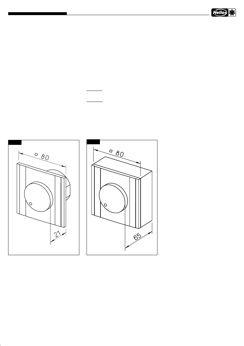
Fig. 2
13.0 Données techniques
Boîtier en matière synthétique, blanc,
Protection IP 40
Potentiomètre :
env. 7,9 - 16,5 kOhm
(selon la position du poti min.)
24 V DC max.
Interrupteur :
24 V DC / 0,5 A max.
LED :
PU/A 10
Alimentation 10 V DC min. 6 mA
PU/A 24
Alimentation 24 V DC min. 6 mA
Mesures de montage apparentMesures de montage encastré
Fig. 3
Bornes de raccordement :
monofilaire 0,5 - 1,5 mm²
embout 0,25 - 1,0 mm²
Long. de dénudage 9 - 10 mm
Plage de temp. ambiante permise :
0 - 40 °C
Mesures :
L 80 x H 80 x P 65
Plan de raccordement :
SS-1000
2
Page 11
Helios Ventilateurs
10V/24V
10V/24V
10V/24V
Potentiomètre de vitesse PU/A ..
14.0 Plan de raccordement SS-1000
Fig. 4
PU/A 10/24
1
R 1
Potentiomètre
Vit. min.
S 1
2
3
4
5
LED 1
LED 2
6
7
GND / -
Consigne 0-10V
Alimentation potentiomètre+10V
Alimentation signal d'activation, (max. 24VDC/0,5A)
Autorisation de mise en route ventilateur
Alimentation LED 1,
PU/A 10=+10VDC ou PU/A 24=+24VDC, min. 6mA
Signal supplémentaire LED 2, PU/A 10=+10VDC ou PU/A 24=+24VDC, min. 6mA
Exemple :
PU/A 24
Potentiomètre
Vit. min.
LED 1
LED 2
85208 001 SS-1000 19.02.14
15.0 Schéma de principe
Fig. 5
R 1
S 1
Potentiomètre de
régulation
progressive
Autorisation*
Borne 1/6
Borne 1/7
Affichage LED
Fonctionnement affichage LED
10V/24V
0V
vert (2)
rouge (1)
1
2
3
4
5
6
7
Commande : Remarque MBVSuivre la notice d'installation et de montage!
0V
0V
0V
Ventilateur EC
GND
0-10V
+10VDC
+24VDC
Autorisation
Signa de commande
(consigne) ventilateur
Autorisation mise en route
du ventilateur
Relai état de
fonctionnement
Ventilateur
EC
Alimentation
Ventilateur
1~ / 3~
Voyant de
fonctionnement
*Selon le type de ventilateur.
3
Page 12

Notice à garder à proximité de l’appareil ! N° réf. 82 525/02.14
Service / Information
D HELIOS Ventilatoren GmbH & Co · Lupfenstraße 8 · 78056 VS-Schwenningen
A HELIOS Ventilatoren · Postfach 854 · Siemensstraße 15 · 6023 Innsbruck
F HELIOS Ventilateurs · Le Carré des Aviateurs · 157 av. Charles Floquet · 93155 Le Blanc Mesnil Cedex
CH HELIOS Ventilatoren AG · Steinackerstraße 36 · 8902 Urdorf /Zürich
GB HELIOS Ventilation Systems Ltd. · 5 Crown Gate · Wyncolls Road · Severalls Industrial Park · Colchester · Essex · CO4 9HZ
www.heliosventilatoren.de
 Loading...