

Page 1
MONTAGE- UND BETRIEBSVORSCHRIFT NR. 19052.005
INSTALLATION AND OPERATING INSTRUCTIONS NO. 19052.005
NOTICE DE MONTAGE ET D’UTILISATION N° 19052.005
IP 45
Kleinlüfter - Mini fan - Mini ventilateur
Helios MiniVent
M1/100/120 N / C
- mit codierbarem Nachlauf- und Intervallbetrieb
- with codabel overrun timer and interval operation
- avec minuterie programmable et temporisation
D
UK
F
Page 2

DEUTSCH
Inhaltsverzeichnis
KAPITEL 1. ALLGEMEINE HINWEISE . . . . . . . . . . . . . . . . . . . . . . . . . . . . . . . . . . . . . . . . . . . . . . . . . . . . . . . . . .Seite 1
1.0 Wichtige Informationen . . . . . . . . . . . . . . . . . . . . . . . . . . . . . . . . . . . . . . . . . . . . . . . . . . . . . . . . . . . . . . . . .Seite 1
1.1 Warnhinweise . . . . . . . . . . . . . . . . . . . . . . . . . . . . . . . . . . . . . . . . . . . . . . . . . . . . . . . . . . . . . . . . . . . . . . . .Seite 1
1.2 Sicherheitshinweise . . . . . . . . . . . . . . . . . . . . . . . . . . . . . . . . . . . . . . . . . . . . . . . . . . . . . . . . . . . . . . . . . . . .Seite 1
1.3 Garantieansprüche – Haftungsausschluss . . . . . . . . . . . . . . . . . . . . . . . . . . . . . . . . . . . . . . . . . . . . . . . . . . .Seite 2
1.4 Vorschriften – Richtlinien . . . . . . . . . . . . . . . . . . . . . . . . . . . . . . . . . . . . . . . . . . . . . . . . . . . . . . . . . . . . . . . .Seite 2
1.5 Transport . . . . . . . . . . . . . . . . . . . . . . . . . . . . . . . . . . . . . . . . . . . . . . . . . . . . . . . . . . . . . . . . . . . . . . . . . . . .Seite 2
1.6 Sendungsannahme . . . . . . . . . . . . . . . . . . . . . . . . . . . . . . . . . . . . . . . . . . . . . . . . . . . . . . . . . . . . . . . . . . . .Seite 2
1.7 Einlagerung . . . . . . . . . . . . . . . . . . . . . . . . . . . . . . . . . . . . . . . . . . . . . . . . . . . . . . . . . . . . . . . . . . . . . . . . . .Seite 2
1.8 Einsatzbereich . . . . . . . . . . . . . . . . . . . . . . . . . . . . . . . . . . . . . . . . . . . . . . . . . . . . . . . . . . . . . . . . . . . . . . . .Seite 2
1.9 Leistungsdaten . . . . . . . . . . . . . . . . . . . . . . . . . . . . . . . . . . . . . . . . . . . . . . . . . . . . . . . . . . . . . . . . . . . . . . .Seite 3
1.10 Geräuschangaben . . . . . . . . . . . . . . . . . . . . . . . . . . . . . . . . . . . . . . . . . . . . . . . . . . . . . . . . . . . . . . . . . . . . .Seite 3
KAPITEL 2. ALLGEMEINE BETRIEBSHINWEISE . . . . . . . . . . . . . . . . . . . . . . . . . . . . . . . . . . . . . . . . . . . . . . . . .Seite 3
2.0 Personalqualifikation . . . . . . . . . . . . . . . . . . . . . . . . . . . . . . . . . . . . . . . . . . . . . . . . . . . . . . . . . . . . . . . . . . .Seite 3
2.1 Berührungsschutz . . . . . . . . . . . . . . . . . . . . . . . . . . . . . . . . . . . . . . . . . . . . . . . . . . . . . . . . . . . . . . . . . . . . .Seite 3
2.2 Motorschutz . . . . . . . . . . . . . . . . . . . . . . . . . . . . . . . . . . . . . . . . . . . . . . . . . . . . . . . . . . . . . . . . . . . . . . . . .Seite 3
KAPITEL 3. TECHNISCHE DATEN/ABMESSUNGEN . . . . . . . . . . . . . . . . . . . . . . . . . . . . . . . . . . . . . . . . . . . . . .Seite 3
3.0 Typenübersicht MiniVent M1/1... N / C . . . . . . . . . . . . . . . . . . . . . . . . . . . . . . . . . . . . . . . . . . . . . . . . . . . . .Seite 3
3.1 Technische Daten . . . . . . . . . . . . . . . . . . . . . . . . . . . . . . . . . . . . . . . . . . . . . . . . . . . . . . . . . . . . . . . . . . . . .Seite 3
3.2 Zubehör . . . . . . . . . . . . . . . . . . . . . . . . . . . . . . . . . . . . . . . . . . . . . . . . . . . . . . . . . . . . . . . . . . . . . . . . . . . .Seite 4
3.3 Produktlebensdauer . . . . . . . . . . . . . . . . . . . . . . . . . . . . . . . . . . . . . . . . . . . . . . . . . . . . . . . . . . . . . . . . . . .Seite 4
3.4 Abmessungen . . . . . . . . . . . . . . . . . . . . . . . . . . . . . . . . . . . . . . . . . . . . . . . . . . . . . . . . . . . . . . . . . . . . . . . .Seite 4
KAPITEL 4. FUNKTION . . . . . . . . . . . . . . . . . . . . . . . . . . . . . . . . . . . . . . . . . . . . . . . . . . . . . . . . . . . . . . . . . . . . .Seite 5
4.0 Funktionsbeschreibung M1/100/120 N / C . . . . . . . . . . . . . . . . . . . . . . . . . . . . . . . . . . . . . . . . . . . . . . . . . .Seite 5
KAPITEL 5. REINIGUNG/DEMONTAGE . . . . . . . . . . . . . . . . . . . . . . . . . . . . . . . . . . . . . . . . . . . . . . . . . . . . . . . . .Seite 6
5.0 Reinigung . . . . . . . . . . . . . . . . . . . . . . . . . . . . . . . . . . . . . . . . . . . . . . . . . . . . . . . . . . . . . . . . . . . . . . . . . . .Seite 6
5.1 Demontage der Fassade . . . . . . . . . . . . . . . . . . . . . . . . . . . . . . . . . . . . . . . . . . . . . . . . . . . . . . . . . . . . . . . .Seite 6
KAPITEL 6. INSTALLATION . . . . . . . . . . . . . . . . . . . . . . . . . . . . . . . . . . . . . . . . . . . . . . . . . . . . . . . . . . . . . . . . .Seite 7
6.0 Lieferumfang / Konstruktiver Aufbau . . . . . . . . . . . . . . . . . . . . . . . . . . . . . . . . . . . . . . . . . . . . . . . . . . . . . . .Seite 7
6.1 Vorbereitung zur Wand- oder Deckenmontage (Aufputz) . . . . . . . . . . . . . . . . . . . . . . . . . . . . . . . . . . . . . . . .Seite 7
6.2 Installation . . . . . . . . . . . . . . . . . . . . . . . . . . . . . . . . . . . . . . . . . . . . . . . . . . . . . . . . . . . . . . . . . . . . . . . . . . .Seite 7
6.3 Elektrischer Anschluss . . . . . . . . . . . . . . . . . . . . . . . . . . . . . . . . . . . . . . . . . . . . . . . . . . . . . . . . . . . . . . . . . .Seite 9
6.4 Anschluss der Zuleitung / Inbetriebnahme . . . . . . . . . . . . . . . . . . . . . . . . . . . . . . . . . . . . . . . . . . . . . . . . . . .Seite 9
6.5 Einbau . . . . . . . . . . . . . . . . . . . . . . . . . . . . . . . . . . . . . . . . . . . . . . . . . . . . . . . . . . . . . . . . . . . . . . . . . . . . .Seite 10
6.6 Betrieb . . . . . . . . . . . . . . . . . . . . . . . . . . . . . . . . . . . . . . . . . . . . . . . . . . . . . . . . . . . . . . . . . . . . . . . . . . . .Seite 11
KAPITEL 7. FUNKTION FÜR INSTALLATEUR . . . . . . . . . . . . . . . . . . . . . . . . . . . . . . . . . . . . . . . . . . . . . . . . . . .Seite 11
7.0 Funktion M1/100/120 N / C . . . . . . . . . . . . . . . . . . . . . . . . . . . . . . . . . . . . . . . . . . . . . . . . . . . . . . . . . . . .Seite 11
7.1 Schaltplanübersicht für M1/100/120 N / C . . . . . . . . . . . . . . . . . . . . . . . . . . . . . . . . . . . . . . . . . . . . . . . . .Seite 13
KAPITEL 8. INSTANDHALTUNG UND WARTUNG . . . . . . . . . . . . . . . . . . . . . . . . . . . . . . . . . . . . . . . . . . . . . . .Seite 14
8.0 Instandhaltung und Wartung . . . . . . . . . . . . . . . . . . . . . . . . . . . . . . . . . . . . . . . . . . . . . . . . . . . . . . . . . . . .Seite 14
8.1 Störungsursachen . . . . . . . . . . . . . . . . . . . . . . . . . . . . . . . . . . . . . . . . . . . . . . . . . . . . . . . . . . . . . . . . . . . .Seite 14
8.2 Stilllegen und Entsorgen . . . . . . . . . . . . . . . . . . . . . . . . . . . . . . . . . . . . . . . . . . . . . . . . . . . . . . . . . . . . . . .Seite 14
Page 3
Montage- und Betriebsvorschrift
KAPITEL 1
ALLGEMEINE HINWEISE
GEFAHR
WARNUNG
VORSICHT
1.0 Wichtige Informationen
1.1 Warnhinweise
1.2 Sicherheitshinweise
GEFAHR
MiniVent M1/100/120 N / C
Zur Sicherstellung einer einwandfreien Funktion und zur eigenen Sicherheit sind alle nachstehenden Vorschriften genau
durchzulesen und zu beachten.
Dieses Dokument ist Teil des Produktes und als solches zugänglich und dauerhaft aufzubewahren um einen sicheren
Betrieb des Ventilators zu gewährleisten. Alle anlagenbezogenen Sicherheitsvorschriften müssen eingehalten werden.
Nebenstehende Symbole sind sicherheitstechnische Warnhinweise. Zur Vermeidung jeglichen Verletzungsrisikos und Gefahrensituation, müssen alle
Sicherheitsvorschriften bzw. Symbole in diesem Dokument unbedingt beachtet
werden!
Für Einsatz, Anschluss und Betrieb gelten besondere Bestimmungen; bei Zweifel ist
Rückfrage erforderlich. Weitere Informationen sind den einschlägigen Normen und
Gesetzestexten zu entnehmen.
Bei allen Arbeiten am Ventilator sind die allgemein gültigen Arbeitsschutz-
und Unfallverhütungsvorschriften einzuhalten!
• Alle elektrischen Arbeiten, sowie die Inbetriebnahme, Wartungs- und Installationsarbeiten dürfen nur von autorisiertem Elektrofachpersonal durchgeführt werden!
• Vor allen Reinigungs-, Wartungs- und Installationsarbeiten oder vor Öffnen des
Anschlussraums sind folgende Punkte einzuhalten:
– Gerät allpolig vom Netz trennen und gegen Wiedereinschalten sichern!
– Der Stillstand rotierender Teile ist abzuwarten!
– Nach dem Stillstand rotierender Teile ist eine Wartezeit von 3 min. einzuhalten, da durch interne Kondensatoren auch nach der Trennung vom Netz gefährliche Spannungen auftreten können!
• Alle anlagenbezogenen Sicherheitsvorschriften sind einzuhalten!
Gegebenenfalls müssen weitere länderspezifische Vorschriften eingehalten werden!
• Eine gleichmäßige Zuströmung und ein freier Ausblas sind zu gewährleisten!
• Bei Betrieb von schornsteinabhängigen Feuerstellen im entlüfteten Raum muss
bei allen Betriebsbedingungen für ausreichend Zuluft gesorgt werden (Rückfrage
beim Schornsteinfeger). Die örtlich aktuell gültigen Vorschriften und Gesetzen sind
zu beachten!
• MiniVent M1/100/120 N / C Kleinventilatoren können von Kindern ab 8 Jahren
und darüber sowie von Personen mit verringerten physischen, sensorischen oder
mentalen Fähigkeiten oder Mangel an Erfahrung und Wissen benutzt werden,
wenn sie beaufsichtigt oder bezüglich des sicheren Gebrauchs des Gerätes unterwiesen wurden und die daraus resultierenden Gefahren verstehen. Kinder dürfen nicht mit dem Gerät spielen. Reinigung und Benutzer-Wartung darf nicht von
Kindern ohne Beaufsichtigung durchgeführt werden.
D
1
Page 4

Montage- und Betriebsvorschrift
D
1.3 Garantieansprüche – Haftungsausschluss
WICHTIG
HINWEIS
HINWEIS
HINWEIS
1.4 Vorschriften – Richtlinien
☞
1.5 Transport
1.6 Sendungsannahme
1.7 Einlagerung
1.8 Einsatzbereich
☞
☞
☞
MiniVent M1/100/120 N / C
Alle Ausführungen dieser Dokumentation müssen beachtet werden, sonst entfällt die Gewährleistung. Gleiches gilt für
Haftungsansprüche an Helios. Der Gebrauch von Zubehörteilen, die nicht von Helios empfohlen oder angeboten werden, ist nicht statthaft. Eventuell auftretende Schäden unterliegen nicht der Gewährleistung. Veränderungen und Umbauten am Gerät sind nicht zulässig und führen zum Verlust der Konformität, jegliche Gewährleistung und Haftung ist
in diesem Fall ausgeschlossen.
Bei ordnungsgemäßer Installation und bestimmungsgemäßem Betrieb entspricht das Gerät den zum Zeitpunkt seiner
Herstellung gültigen Vorschriften und EU-Richtlinien.
Der Ventilator ist werkseitig so verpackt, dass er gegen normale Transportbelastungen geschützt ist. Führen Sie den
Transport sorgfältig durch. Es wird empfohlen, den Ventilator in der Originalverpackung zu belassen.
Die Sendung sofort bei Anlieferung auf Beschädigungen und Typenrichtigkeit prüfen. Falls Schäden vorliegen umgehend Schadensmeldung unter Hinzuziehung des Transportunternehmens veranlassen. Bei nicht fristgerechter Reklamation gehen evtl. Ansprüche verloren.
Bei Einlagerung über längeren Zeitraum sind zur Verhinderung schädlicher Einwirkungen folgende Maßnahmen zu treffen: Schutz des Motors durch trockene, luft- und staubdichte Verpackung (Kunststoffbeutel mit Trockenmittel und
Feuchtigkeitsindikatoren). Erschütterungsfreie, wassergeschützte und temperaturkonstante Lagerung bei einer Temperatur zwischen -20 °C bis +40 °C.
Bei einer Lagerdauer über drei Monate bzw. Motorstillstand, muss vor Inbetriebnahme eine Wartung laut Kapitel 8 erfolgen. Bei Weiterversand (vor allem über längere Distanzen; z.B. Seeweg) ist zu prüfen, ob die Verpackung für Transportart und -weg geeignet ist. Schäden, deren Ursache in unsachgemäßem Transport, Einlagerung oder Inbetriebnahme liegen, sind nachweisbar und unterliegen nicht der Gewährleistung.
– Bestimmungsgemäßer Einsatz:
Die MiniVent M1/100/120 N / C Kleinventilatoren sind zur Förderung normaler oder leicht staubhaltiger (Partikelgröße
< 10 µm), wenig aggressiver und feuchter Luft, in gemäßigtem Klima und im Bereich ihrer Leistungskennlinie geeignet, siehe Helios Verkaufsunterlagen/Internet. Zulässig ist ein Betrieb nur bei Festinstallation innerhalb von Gebäuden.
Die maximal zulässige Medium- u. Umgebungstemperatur beträgt 40 °C. MiniVent M1/100/120 N / C Kleinventilatoren
entsprechen Schutzart IP45, Schutzklasse II und dürfen entsprechend VDE 0100 Teil 701 in den Bereich 1 von Nassräumen installiert werden.
– Vernünftigerweise vorhersehbarer Fehlgebrauch:
Die Ventilatoren sind nicht zum Betrieb unter erschwerten Bedingungen wie z.B. hohe Feuchtigkeit, aggressive Medien, längere Stillstandzeiten, starke Verschmutzung, übermäßige Beanspruchung durch klimatische, technische oder
elektronische Einflüsse geeignet. Gleiches gilt für die mobile Verwendung der Ventilatoren (Fahr-, Flugzeuge, Schiffe,
usw.). Ein Einsatz unter diesen Bedingungen ist nur mit Einsatzfreigabe seitens Helios möglich, da die Serienausführung hierfür nicht geeignet ist.
– Missbräuchlicher, untersagter Einsatz:
Ein bestimmungsfremder Einsatz ist nicht zulässig! Die Förderung von Feststoffen oder Feststoffanteilen > 10 µm im
Fördermedium sowie Flüssigkeiten ist nicht gestattet. Fördermedien, die die Werkstoffe des Ventilators angreifen, sowie abrasive Medien sind nicht zulässig. Der Einsatz in explosionsgefährdeten Bereichen ist nicht gestattet!
2
Page 5
Montage- und Betriebsvorschrift
1.9 Leistungsdaten
1.10 Geräuschangaben
KAPITEL 2
ALLGEMEINE
BETRIEBSHINWEISE
KAPITEL 3
TECHNISCHE DATEN /
ABMESSUNGEN
2.0 Personalqualifikation
2.1 Berührungsschutz
2.2 Motorschutz
3.0 Typenübersicht MiniVent M1/1.. N / C
3.1 Technische Daten
MiniVent M1/100/120 N / C
Das Gerätetypenschild gibt über die verbindlichen elektrischen Werte Aufschluss; diese müssen mit dem örtlichen Versorgungsnetz abgestimmt sein. Die Ventilatorleistungen wurden auf einem Prüfstand entsprechend DIN EN ISO 5801
ermittelt.
Die Geräuschangaben, die sich auf Abstände beziehen gelten für Freifeldbedingungen. Der Schalldruckpegel kann im
Einbaufall erheblich von der Katalogangabe abweichen, da er stark von den Einbaugegebenheiten, d.h. vom Absorptionsvermögen des Raumes, der Raumgröße u.a. Faktoren abhängig ist.
Die Elektroanschlüsse und Inbetriebnahme sowie Installations-, Instandhaltungs- und Wartungsarbeiten
des Ventilators dürfen nur von Elektrofachkräften ausgeführt werden.
– MiniVent M1/100/120 N / C Kleinventilatoren können von Kindern ab 8 Jahren und darüber sowie von Personen mit
verringerten physischen, sensorischen oder mentalen Fähigkeiten oder Mangel an Erfahrung und Wissen benutzt
werden, wenn sie beaufsichtigt oder bezüglich des sicheren Gebrauchs des Gerätes unterwiesen wurden und die
daraus resultierenden Gefahren verstehen. Kinder dürfen nicht mit dem Gerät spielen. Reinigung und BenutzerWartung darf nicht von Kindern ohne Beaufsichtigung durchgeführt werden.
MiniVent M1/100/120 N / C Kleinventilatoren benötigen kein Schutzgitter, da sie die Anforderungen aus DIN EN
60335-2-80 Punkt 20.101 erfüllen.
Die Motoren des MiniVent M1/100/120 N / C sind mit Thermokontakten ausgestattet, die mit der W icklung in Reihe
verdrahtet, selbsttätig aus- und nach erfolgter Abkühlung wiedereinschalten.
M1/100 N / C mit codierbarem Nachlauf- und Intervallbetrieb Best.Nr. 6172.003
M1/120 N / C mit codierbarem Nachlauf- und Intervallbetrieb Best.Nr. 6361.003
M1/100 N / C
Laufrad-Ø [mm] 92 Elektrische Zuleitung NYM-O 3 x 1,5 mm²
Wechselstrom 1~ Schutzart IP 45 (strahlwassergeschützt)
Spannung/Frequenz 230 V, 50 Hz Schutzklasse II
Leistungsaufnahme [W] 9/5 Gewicht ca. [kg] 0,8
Nennstrom [mA] 0,06/0,04 Drehzahl [1/min] 2650/2250
Fördervolumen [m
M1/120 N / C
Laufrad-Ø [mm] 111 Elektrische Zuleitung NYM-O 3 x 1,5 mm²
Wechselstrom 1~ Schutzart IP 45 (strahlwassergeschützt)
Spannung/Frequenz 230 V, 50 Hz Schutzklasse II
Leistungsaufnahme [W] 13/10 Gewicht ca. [kg] 1,05
Nennstrom [mA] 0,09/0,08 Drehzahl [1/min] 2350/2050
Fördervolumen [m
3
/h] 90/75
3
/h] 170/150
D
3
Page 6
Montage- und Betriebsvorschrift
D
3.2 Zubehör
3.3 Produktlebensdauer
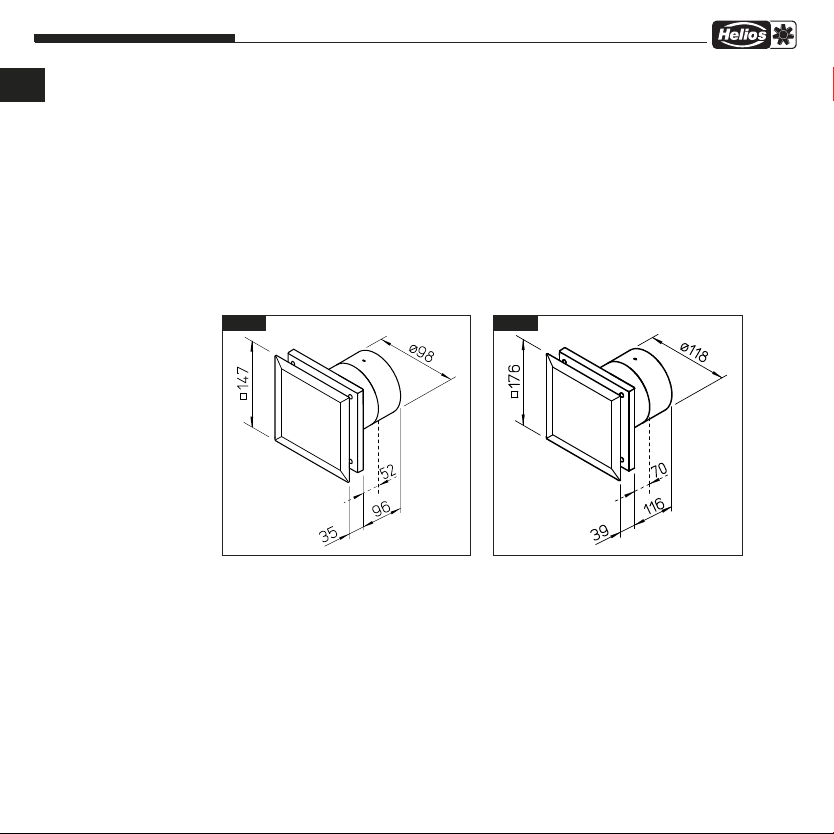
3.4 Abmessungen
MiniVent M1/100/120 N / C
WES 100 Wandeinbauset Best.Nr. 0717
WES 120 Wandeinbauset Best.Nr. 0486
MF 100 Montageflansch Best.Nr. 6188
TWH 100 Teleskop-Wandhülse Best.Nr. 6352
TWH 120 Teleskop-Wandhülse Best.Nr. 6353
MBR Montageblende Best.Nr. 0281
Dieses Gerät ist auf eine Produktlebensdauer von mindestens 40.000 h, bei S1-Betrieb mit maximaler Leistung in
maximal zulässiger Umgebungstemperatur ausgelegt.
M1/100 N / C M1/120 N / C
Abb.2Abb.1
Alle Maße in mm Alle Maße in mm
4
Page 7
Montage- und Betriebsvorschrift
KAPITEL 4
FUNKTION
GEFAHR
HINWEIS
4.0 Funktionsbeschreibung M1/100/120 N / C
MiniVent M1/100/120 N / C
Mit integrierter, Intervall-Steuerung, die einen automatischen Ventilatorbetrieb in vorgegebenen zeitlichen Abständen er
möglicht. Der Ventilator kann mit einem externen Schalter (evtl. mit Licht gekoppelt) mit ca. 45 sec. Anlaufverzögerung
und ca. 6 Minuten Nachlauf, aktiviert werden (Zeiteingang). Dies setzt die Intervallzeit zurück, sie startet nach Ablauf
des Nachlaufs neu. Parallel ist auch eine manuelle Steuerung (Ein/Aus) über einen Schalter möglich, diese ist dem
Zeiteingang untergeordnet.
Einstellungsmöglichkeiten / Werkseinstellungen*:
- Einschaltverzögerung: 0, 45 Sek*., 90 Sek., 120 Sek.
- Nachlauf: 6*, 10, 15, 21 Min.
- Anstatt der Einschaltverzögerung kann auch ein Taster (Tastimpuls min. 0,5 Sek.) angeschlossen werden, der bei
Betätigung den Ventilator für die festgelegte Nachlaufzeit einschaltet
- Intervallbetrieb: 0 Std, 8 Std, 12 Std, 24 Std; kleine Stufe, große Stufe
- Manuelle Steuerung (Schalter): kleine Stufe, große Stufe
Eine Änderung der Einstellungen darf nur von einer autorisierten Elektrofachkraft durchgeführt werden!
Folgende Funktionen sind implementiert:
Einschaltverzögerung
Nach dem Einschalten beginnt der Ventilator erst nach der eingestellten Verzögerungszeit zu laufen. So kann z. B. bei
gemeinsamer Ein-/Ausschaltung mit dem Licht (über 2 pol. Schalter) ein Raum kurzzeitig betreten werden, ohne dass
der Ventilator in Betrieb geht.
Nachlauf
Nach dem Abschalten läuft der Ventilator weiter und geht nach Ablauf der eingestellten Zeit automatisch aus.
Intervallbetrieb
Der Ventilator kann in einstellbaren Zeitabständen automatisch in Betrieb gesetzt werden. Nach der eingestellten Nachlaufzeit schaltet er automatisch aus.
Die Intervallzeit beginnt nach dem letzten Ausschaltvorgang am Zeiteingang, auch bei zwischenzeitlichem manuellen
Betrieb. Der manuelle Betrieb hat keinen Einfluss auf den Intervallbetrieb. Die Einschaltzeit im Intervallbetrieb entspricht
der eingestellten Nachlaufzeit.
Im Auslieferungszustand ist der Intervallbetrieb deaktiviert.
Testmodus
Nach Spannungsfreiheit (Stromausfall, Sicherung, usw.) befindet sich der Ventilator für 1 min im Testmodus (Voraussetzung: Gerät mit Werkseinstellung). Hierbei sind die Einschaltverzögerung und der Nachlauf innerhalb der ersten
Minute, bzw. für einen Schaltzyklus, deaktiviert.
D
5
Page 8
Montage- und Betriebsvorschrift
D
KAPITEL 5
REINIGUNG/
DEMONTAGE
GEFAHR
5.0 Reinigung
5.1 Demontage der Fassade
MiniVent M1/100/120 N / C
Es sind die in Kapitel 1.2 aufgeführten Sicherheitshinweise zu beachten!
– Vor Beginn der Reinigung ist sicherzustellen, dass der Ventilator allpolig vom Netz getrennt und gegen Wiederein-
schalten gesichert wurde!
– Fassade und sichtbare Gehäuseteile mit einem feuchten Tuch reinigen
– Keine aggressiven, lacklösenden Reinigungsmittel verwenden!
– Hochdruckreiniger oder Strahlwasser ist nicht gestattet!
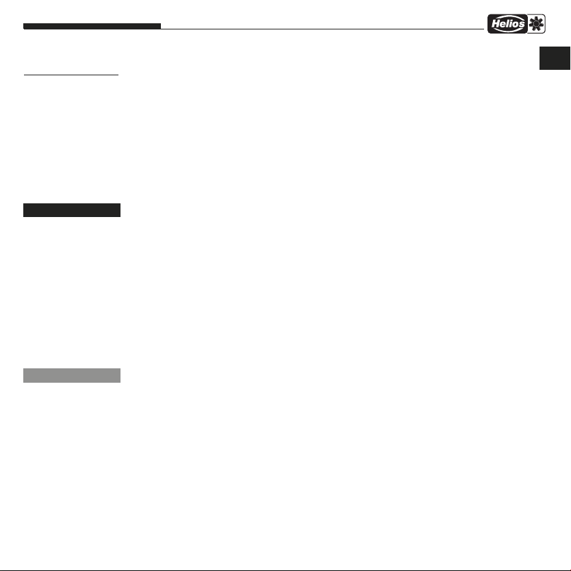
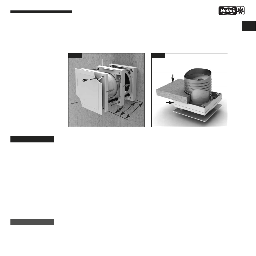
Vorgehensweise:
1. Gerät spannungsfrei schalten und gegen Wiedereinschalten sichern!
2. Durch drücken der Schnapphaken, kann die Fassade
und abgenommen werden (Abb. 3/4).
➊ entriegelt
Abb.3
Durch drücken der
2 Schnapphaken
Fassade entriegeln
und abnehmen.
➊
Abb.4
➊
6
Page 9
Montage- und Betriebsvorschrift
ACHTUNG
Alle nachfolgenden Informationen und Anweisungen sind nur für eine
autorisierte Elektrofachkraft bestimmt!
MiniVent M1/100/120 N / C
D
KAPITEL 6
INSTALLATION
WARNUNG
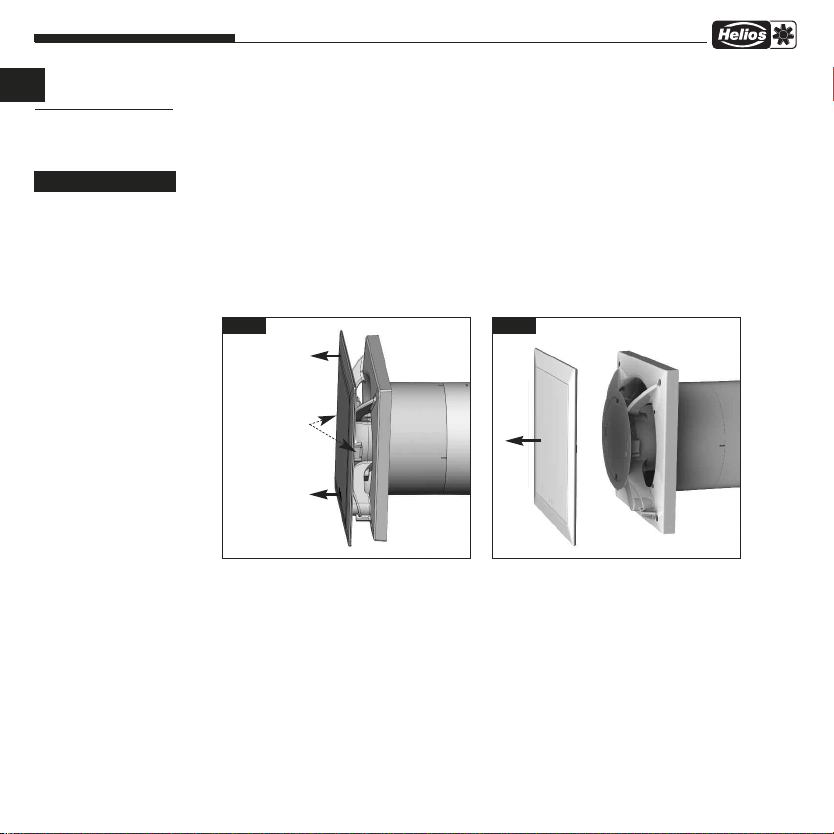
6.0 Lieferumfang / Konstruktiver Aufbau
Entnehmen Sie die Liefereinheit erst unmittelbar vor dem Einbau aus dem Karton, um mögliche Beschädigungen
und Verschmutzungen beim Transport sowie auf der Baustelle zu vermeiden.
MiniVent M1/100/120 N / C
➌
➋
Abb.5
➊ Fassade
➋ Anschlussraumabdeckung
➏
➎
➐
inkl. 2x Befestigungsschrauben
➌ Steuerplatine
➍ Kunststoffgehäuse mit Laufrad
➎ Nachleitrad bei eingeschränkter Einbautiefe abnehmbar
➏ Rückluftsperrklappe abnehmbar
➐ Kabeltülle
➑ Montagesatz
2x Schrauben inklusive Dübel für Wandbefestigung
➍
➑
➊
6.1 Vorbereitung zur Wand- oder Deckenmontage (Aufputz)
Es sind die in Kapitel 1.2 aufgeführten Sicherheitshinweise zu beachten!
Der Ventilator wird serienmäßig als komplette Einheit, d.h. anschlussfertig geliefert. Die Montage und Inbetriebnahme
des Ventilators sollte erst nach Abschluss aller anderen Gewerke und nach der Endreinigung erfolgen, um Beschädigungen und Verschmutzung des Lüftungsgerätes zu vermeiden.
Nach Entfernen der Verpackung und vor Montagebeginn sind folgende Punkte zu überprüfen:
– liegen Transportschäden vor,
– gebrochene bzw. verbogene Teile
– Freilauf des Laufrades
6.2 Installation
Der M1/100/120 N / C MiniVent ist für direkte Wandmontage ausgelegt. Das Gehäuse darf bei der Montage nicht deformiert oder verzogen werden, es ist auf ebene Beschaffenheit der Einbaufläche zu achten. Die Ventilatoren dürfen nur
an ausreichend feste und tragfähige Untergründe, mit hierfür geeigneten Befestigungsmitteln, montiert werden. Eine
ausreichende Nachströmung ist zu gewährleisten! Ggf. die Anweisungen aus DIN 1946-6 beachten.
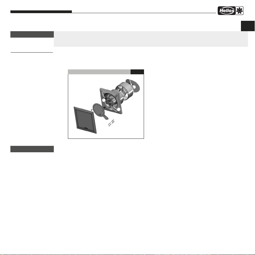
1. Kabelaustritt aus der Wand:
– Die Lage des Kabelaustritts ist im dunklen Bereich variabel (Abb.6).
– Abstand zum Rohrmittelpunkt je nach Kabelaustritt 58/68* mm bei einer variablen Position unter dem Gehäuse.
– Für eine einfache Montage empfiehlt sich ein Austritt wie abgebildet (um jeweils 90° drehbar).
Die optimale Position liegt bei jeweils 45°, wenn sich der Kabelaustritt direkt an der Position der Kabeltülle befindet.
7
Page 10
Montage- und Betriebsvorschrift
D
MiniVent M1/100/120 N / C
– Rohrinnendurchmesser M1/100 N / C = 100 mm bzw. M1/120 N / C = 120 mm
und Abstand zu Raum-Ecken: mindestens 90 mm.
– Bei Aufputzleitungsverlegung, muss die seitliche Aussparung für den Kabeleintritt (Abb.9, Pos
gebrochen werden!
– Das Anschlusskabel ist so zu verwahren, dass bei Wasserbeaufschlagung kein Wasser entlang des Kabels ein-
dringen kann. Das Kabel darf nicht über scharfe Kanten geführt werden!
Abb.6
abelaustritt
K
im dunklen
Bereich beliebig möglich
min. 90 mm
* Type M1/120..
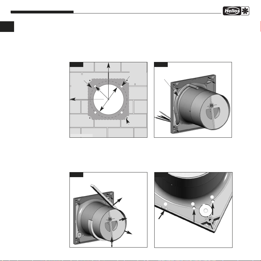
2. Bohrlöcher:
Gehäuse ansetzen Löcher markieren und abbohren und mit mind. zwei Befestigungsschrauben und Dübeln montieren.
3. Rückluftsperrklappe und Nachleitrad
– Bei Einbau des Gerätes, muss das Nachleitrad senkrecht montiert werden (Abb.8).
Rasterung jeweils um 90° drehbar.
– Vor der Endmontage Schaumstoffstreifen (Lieferumfang) aufkleben (Abb.8)
Abb.8
min. 90 mm
r=58 m
r=68 m
m
m
*
100 mm
Ø
Ø
Bei Einbau des Gerätes, muss das
Nachleitrad
werden (wie dargestellt). Raste-
rung jeweils um 90° drehbar.
➎
senkrecht bei Wandeinbau
Empfohlener
Kabelaustritt
beliebig
0...-360 °,
ideal jeweils
45°
*
m
m
0
2
1
Bohrlöcher
➎ senkrecht montiert
Schaumstoffstreifen
anbringen
oben
Rückluftsperrklappe
abnehmbar
unten
Nachleitrad ➎
abnehmbar
8
Abb.7
Kabelführung unter dem Gehäuse. Kabellänge aus der Wand mindestens
180 mm.
Abb.9
➀
➀ Bei Aufputz-
➏
montage Aussparung
für Kabeleintritt ausbrechen
Kondensatablaufbohrungen
➁
für Deckenmontage.
➁
➂
➀
➁
) im Gehäuse aus
Page 11
Montage- und Betriebsvorschrift
MiniVent M1/100/120 N / C
4. Montageflansch MF 100 (Zubehör)
Bei beengten Platzverhältnissen in Decken, in dünnen Wänden sowie in engen Schächten. MF 100 winkelgerecht an
die Wand oder die Decke dübeln (beliebige Anzahl übereinander möglich). Anschließend Ventilator mittels beigefügten Schrauben an MF 100 befestigen (Abb. 10/11). Auch für Montage eines Zugschnurschalters geeignet (Zubehör).
Abb.10
MF 100 aufsteckbar
Abb.11
Decke
D
GEFAHR
WARNUNG
12
32
E
i
n
Wand
6.3 Elektrischer Anschluss
Es sind die in Kapitel 1.2 aufgeführten Sicherheitshinweise zu beachten!
– Der elektrische Anschluss, bzw. die Erstinbetriebnahme darf nur von einer autorisierten Elektrofachkraft
entsprechend den Angaben in den beiliegenden Anschlussplänen ausgeführt werden.
– Die einschlägigen Normen, Sicherheitsbestimmungen (z. B. DIN VDE 0100) sowie die Technischen Anschlus-
sbedingungen der Energieversorgungsunternehmen sind unbedingt zu beachten!
– Ein allpoliger Netztrennschalter/Revisionsschalter, mit mindestens 3 mm Kontaktöffnung (VDE 0700 T1
7.12.2 / EN 60335-1) ist zwingend vorgeschrieben!
– Netzform, Spannung und Frequenz müssen mit den Angaben des Leistungsschildes übereinstimmen.
6.4 Anschluss der Zuleitung / Inbetriebnahme
– Es ist eine NYM-Leitung einzusetzen, handelsüblicher maximaler Durchmesser 11 mm
– Tülle mit rundem Werkzeug vorstechen oder mit der Zuleitung direkt durchstechen (Abb.9, Pos
– Mantel auf 100 mm entfernen. Drähte 7 mm abisolieren (Abb.12)
– Leitung vorsichtig durch die Tülle schieben
– Drähte im Leitungskanal verlegen und laut Schaltplan (Seite 13) anschließen
– Abdichtung des Anschlusskabels und festen Klemmsitz der Adern prüfen
– Falls bei montierter Zuleitung die Tülle die Mantelleitung nicht gleichmäßig umschließt, muss die Tülle z.B. mit Silikon
zusätzlich abgedichtet werden. Ansonsten erlischt der IP-Schutz
– Das Anschlusskabel ist so zu verwahren, dass bei Wasserbeaufschlagung kein Wasser entlang des Kabels eindrin-
gen kann. Das Kabel darf nicht über scharfe Kanten geführt werden!
– Bestimmungsgemäßen Einsatz des Ventilators überprüfen
– Netzspannung mit Typenschildangabe vergleichen
– Ventilator auf solide Befestigung und fachgerechte elektrische Installation prüfen
baut
52
ie
fe
9
MF 100
)
➂
Page 12
Montage- und Betriebsvorschrift
D
WARNUNG
MiniVent M1/100/120 N / C
– Freilauf des Laufrades prüfen
– Alle Teile, insbesondere Schrauben, auf festen Sitz überprüfen. Schrauben dabei nicht lösen!
– Beim Probelauf den Ventilator auf Vibrationen und Geräusche prüfen
– Stromaufnahme mit Leistungsschildangabe vergleichen
Abb.12 Abb.13
➊
➋
➌
Dichtmasse
7 mm
100 mm
- Länge Einzeladern 100 mm
- Abisolierlänge 7 mm
- Mantelleitung bündig mit Kabelkanal abisolieren
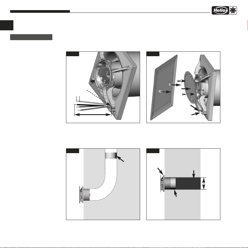
6.5 Einbau
Rohrführung
90° Bogen
Montage bei beengten
Platzverhältnissen
Nachleitrad
mit Verschlussklappe
am Rohrende
oder ohne Verwendung des
Nachleitrades
montieren.
10
Anschlussraumabdeckung einhängen
1. Anschlussraumabdeckung ➋in Nut einhängen,
auf Gehäuse drücken und Schrauben fest eindrehen.
2. Fassade
Abb.15Abb.14
Ventilator
Raumseite außen
einschnappen.
➊
WES 1.. oder
TWH 1..
Nachleitrad mit
Verschlussklappe
Standard Einbau
Kernlochbohrung
M1/100 N / C
= Ø 115 mm
M1/120 N / C
= Ø 130 mm
Page 13

Montage- und Betriebsvorschrift
WARNUNG
KAPITEL 7
FUNKTION FÜR
INSTALLATEUR
GEFAHR
WICHTIG
6.6 Betrieb
7.0 Funktion M1/100/120 N / C
MiniVent M1/100/120 N / C
Es sind die in Kapitel 1.2 aufgeführten Sicherheitshinweise zu beachten!
Zur Gewährleistung der einwandfreien Funktion des Ventilators, ist regelmäßig Folgendes zu prüfen:
– Auftreten von Staub- oder Schmutzablagerungen im Gehäuse bzw. am Motor und Laufrad
– Freilauf des Laufrades
– Auftreten von übermäßigen Schwingungen und Geräuschen
Bei Problemen mit einem der oben aufgeführten Punkte, ist eine Wartung nach den Anweisungen aus Kapitel 8 durch
zuführen.
Es sind die in Kapitel 1.2 aufgeführten Sicherheitshinweise zu beachten!
1. Einschaltverzögerung (0 Sek, 45 Sek, 90 Sek, 120 Sek) DIP-Schalter S1-2 (siehe SS-920.1)
Nach dem Einschalten der Klemme 1, beginnt der Ventilator erst nach der eingestellten Verzögerungszeit zu
laufen. So kann z.B. bei gemeinsamer Ein/Ausschaltung mit dem Licht (über 2 pol. Schalter) ein Raum kurzzeitig betreten werden, ohne dass der Ventilator in Betrieb geht. Werkseinstellung ca. 45 Sekunden.
2. Tasterbetrieb
Bei deaktivierter Einschaltverzögerung „off“, kann der Ventilator auf der Klemme 1, mit einem Taster eingeschaltet
werden (Tastimpuls mind. 0,5 Sek.).
3. Nachlauf (6 min, 10 min, 15 min, 21 min) DIP-Schalter S3+4 (siehe SS-920.1)
Nach dem Abschalten der Klemme 1, läuft der Ventilator weiter und geht nach Ablauf der eingestellten Zeit automatisch aus. Werkseinstellung ca. 6 Minuten.
4. Intervallbetrieb (0 Std, 8 Std, 12 Std, 24 Std) DIP-Schalter S5+6 (siehe SS-920.1)
Der Ventilator kann in einstellbaren Zeitabständen automatisch in Betrieb gesetzt werden. Nach der eingestellten
Nachlaufzeit schaltet er automatisch aus.
Die Intervallzeit beginnt nach dem letzten Ausschaltvorgang an Klemme 1 (Zeiteingang), auch bei zwischenzeitlichen
manuellen Betrieb (Klemme 2). Der manuelle Betrieb hat keinen Einfluss auf den Intervallbetrieb. Die Einschaltzeit im
Intervallbetrieb entspricht der eingestellten Nachlaufzeit. Werkseinstellung 0 Stunden.
Im Auslieferungszustand ist der Intervallbetrieb deaktiviert. Bei gewünschtem Intervall sind die DIP-Schalter entsprechend der Tabelle (siehe SS-920.1) einzustellen.
5. Verändern der Werkseinstellung
DIP-Schalter (siehe SS-920.1). Das Gerät muss allpolig vom Netz getrennt sein!
Beleuchtung
In Verbindung mit der Raumbeleuchtung (Klemme 1 oder 2), muss ein zweipoliger Schalter verwendet werden.
WICHTIG: Parallelschalten
Parallelschalten von mehreren Ventilatoren ist nicht erlaubt.
- Jumper
Abhängig von der Jumperstellung, läuft der Ventilator bei den Typen M1/100 N / C mit 75 bzw. 90 m³/h und bei
M1/120 N / C mit 150 bzw. 170 m³/h.
Jumper 1 (siehe SS-931)
D
11
Page 14

Montage- und Betriebsvorschrift
D
HINWEIS
MiniVent M1/100/120 N / C
– Typen M1/100 N / C
Stellung A - Auslieferzustand
Kl. 1 = 75 m³/h, Aktivierung mit Zeitfunktion
Kl. 2 = 90 m³/h, Aktivierung manuell
Stellung B
Kl. 1 = 90 m³/h, Aktivierung mit Zeitfunktion
Kl. 2 = 75 m³/h, Aktivierung manuell
– Typen M1/120 N / C
Stellung A - Auslieferzustand
Kl. 1 = 150 m³/h, Aktivierung mit Zeitfunktion
Kl. 2 = 170 m³/h, Aktivierung manuell
Stellung B
Kl. 1 = 170 m³/h, Aktivierung mit Zeitfunktion
Kl. 2 = 150 m³/h, Aktivierung manuell
Funktionstest - Testmodus:
Beim Anlegen der Betriebsspannung befindet sich der Ventilator für 1 min im Testmodus
(Voraussetzung: DIP-Schalter in Werkseinstellung, siehe SS-920.1).
Hierbei ist die Einschaltverzögerung und der Nachlauf innerhalb der ersten Minute, bzw. für einen Schaltzyklus, deaktiviert.
12
Page 15

Montage- und Betriebsvorschrift
M1/... N
SS-917
1
2
a) Zeitfunktion
b) manuell Ein
12
LN
N
L
b)a)
M1/... NC
SS-931
M1~
L
N
1
2
Kl.1=
Jumper 1
A / B
A
B
Zeit-Eingang
Manueller-Eingang
12
LN
Kl.2=
Kl.1=
Kl.2=
SCHALTPLAN-ÜBERSICHT
M1/100 N / C
M1/120 N / C
MiniVent M1/100/120 N / C
7.1 Schaltplanübersicht für M1/100/120 N /C
Anschluss Kunde
Internes Funktionsprinzip / Jumperstellung
Rückspannung / Raumbeleuchtung / Glimmlampen
Durch die Elektronik liegt an der Klemme 1 eine „energieschwache“ Rückspannung an. Um bei Verwendung einer Glimmlampe im Schalter ein Dauerglimmen zur vermeiden, kann parallel zur Glimmlampe, ein bauseits zu stellender Kondensator (X2 Kondensator mit 0,33 µF/250 VAC mit Litze) eingesetzt werden.
Um die Elektroniken nicht negativ zu beeinflussen, sind Raumbeleuchtungen generell nur über
zweipoligen Schalter anzuschließen.
D
SS-931
13
Page 16

Montage- und Betriebsvorschrift
S1
12
LN
Einschaltverzögerung
Delayed start
D
émarrage temporisé
Nachlauf /
Einschaltzeit
Intervallzeit,
Einschaltdauer=
Nachlaufzeit
1234
55
off
on
off off
on
off
off
on
on on
off off
on
off
off
on
on on
0 sec
45 sec
6 min
10 min
15 min
21 min
0 Std
8 Std
12 Std
24 Std
DIP-Schalter / Switch / Commutateur
Run on time /
Running time
Temporisation /
Durée de fonctionnement
Interval time
Running time = Run on time
Durée intervalle
Durée de fonctionnement =
Tem p or i s a ti o n
S
off
on
1 2 3 4 5 6
6
off
on
90 sec
120 sec
off
off
on
on
D
MiniVent M1/100/120 N / C
Einstellung der DIP-Schalter
SS-920.1
KAPITEL 8
INSTANDHALTUNG/
WARTUNG
GEFAHR
8.0 Instandhaltung und Wartung
Es sind die in Kapitel 1.2 aufgeführten Sicherheitshinweise zu beachten!
– Vor allen Arbeiten ist sicherzustellen, dass der Ventilator allpolig vom Netz getrennt und gegen Wiedereinschalten
gesichert wurde!
– Grundsätzlich sind die Geräte wartungsfrei, es ist keine Benutzer-Wartung vorgesehen. Alle dennoch notwendigen
Wartungsarbeiten sind von Elektrofachkräften durchzuführen!
– Übermäßige Ablagerungen von Schmutz, Staub, Fetten u.a.m. auf Laufrad, Motor und vor allem zwischen Gehäuse
und Laufrad sind unzulässig, da sie zu Unwucht im Laufrad, Überhitzung des Motors oder zum Blockieren des Laufrads führen können. In solchen Fällen ist das Gerät zu reinigen.
– Im Falle längeren Stillstands ist bei Wiederinbetriebnahme eine Wartung durchzuführen.
Zu prüfen sind:
• sichere Befestigung des Ventilators am Untergrund / an der Anlage, im Zweifelsfall erneuern
• Schmutzablagerungen entfernen
• mechanische Beschädigungen, Gerät stilllegen, beschädigte Teile austauschen
• fester Sitz der Schraubverbindungen, Schrauben dabei nicht lösen!
• Gehäusebeschaffenheit (Risse, Versprödung des Kunststoffs)
• Freilauf des Laufrads, läuft das Laufrad nicht frei, Störungsursachen 8.1 beachten
• Lagergeräusche
• Vibrationen – siehe Störungsursachen 8.1
• Stromaufnahme entsprechend dem Typenschild – siehe Störungsursachen 8.1
14
Page 17

Montage- und Betriebsvorschrift
WARNUNG
WARNUNG
8.1 Störungsursachen
8.2 Stilllegen und Entsorgen
MiniVent M1/100/120 N / C
Es sind die in Kapitel 1.2 aufgeführten Sicherheitshinweise zu beachten!
Fehler
Ventilator startet
nicht
Sicherung löst aus
Vibrationen
Anormale Geräusche
Ventilator bringt die
Leistung (Drehzahl)
nicht
Es sind die in Kapitel 1.2 aufgeführten Sicherheitshinweise zu beachten!
Bauteile und Komponenten des Ventilators, die ihre Lebensdauer erreicht haben, z.B. durch Verschleiß, Korrosion,
mechanische Belastung, Ermüdung und / oder durch andere, nicht unmittelbar erkennbare Einwirkungen, sind nach
erfolgter Demontage entsprechend den nationalen und internationalen Gesetzen und Vorschriften fach- und sachgerecht zu entsorgen. Das Gleiche gilt auch für im Einsatz befindliche Hilfsstoffe wie Öle und Fette oder sonstige Stoffe.
Die bewusste oder unbewusste Weiterverwendung verbrauchter Bauteile wie z.B. Laufräder, Wälzlager, Keilriemen,
etc. kann zu einer Gefährdung von Personen, der Umwelt sowie von Maschinen und Anlagen führen. Die entsprechenden, vor Ort geltenden Betreibervorschriften sind zu beachten und anzuwenden.
Ursachen
– keine Spannung
– Laufrad blockiert
– Motor blockiert
– Windungsschluss im Motor
– Zuleitung bzw. Anschluss
beschädigt
– falsch angeschlossen
– Verschmutzung
– befestigungsbedingte Resonanz
– schleifendes Laufrad
– Lagerschäden
– mechanische Beschädigung
– Unzureichende Luftförderung
– falsche Spannung
– Lagerschäden
– Verschmutzung
– unzureichende Nachströmung
Lösung
Netzspannung prüfen
Anschluss nach Schaltplan überprüfen
Blockade lösen, reinigen, ggf. Laufrad ersetzen
Helios Kundendienst kontaktieren
Helios Kundendienst kontaktieren
Teile erneuern, ggf. Motor ersetzen
(Helios Kundendienst kontaktieren)
Anschluss überprüfen, ändern
reinigen
Befestigung prüfen bzw. ausbessern
Laufrad reinigen, ggf. ersetzen
Helios Kundendienst kontaktieren
Wartung durchführen
Zu- und Abströmung prüfen/freihalten
Anschluss prüfen/ändern
Helios Kundendienst kontaktieren
reinigen
Nachströmungsöffnungen erweitern
D
15
Page 18

Montage- und Betriebsvorschrift
D
Notizen:
MiniVent M1/100/120 N / C
16
Page 19

Montage- und Betriebsvorschrift
Notizen:
MiniVent M1/100/120 N / C
D
17
Page 20

Als Referenz am Gerät griffbereit aufbewahren! Druckschrift-Nr.
Please keep this manual for reference with the unit! Print-No.:
Conservez cette notice à proximité de l’apapreil! N° Réf.
Service / Information
D HELIOS Ventilatoren GmbH & Co · Lupfenstraße 8 · 78056 VS-Schwenningen
A HELIOS Ventilatoren · Postfach 854 · Siemensstraße 15 · 6023 Innsbruck
F HELIOS Ventilateurs · Le Carré des Aviateurs · 157 av. Charles Floquet · 93155 Le Blanc Mesnil Cedex
CH HELIOS Ventilatoren AG · Tannstrasse 4 · 8112 Otelfingen
GB HELIOS Ventilation Systems Ltd. · 5 Crown Gate · Wyncolls Road · Severalls Industrial Park · Colchester · Essex · CO4 9HZ
19052.005/02.15
www.heliosventilatoren.de
Page 21

MONTAGE- UND BETRIEBSVORSCHRIFT NR. 19052.005
INSTALLATION AND OPERATING INSTRUCTIONS NO. 19052.005
NOTICE DE MONTAGE ET D’UTILISATION N° 19052.005
IP 45
Kleinlüfter - Mini fan - Mini ventilateur
Helios MiniVent
M1/100/120 N / C
- mit codierbarem Nachlauf- und Intervallbetrieb
- with codable overrun timer and interval operation
- avec minuterie programmable et temporisation
D
UK
F
Page 22

ENGLISH
Table of contents
CHAPTER 1. GENERAL INFORMATION . . . . . . . . . . . . . . . . . . . . . . . . . . . . . . . . . . . . . . . . . . . . . . . . . . . . . . . .Page 1
1.0 Important information . . . . . . . . . . . . . . . . . . . . . . . . . . . . . . . . . . . . . . . . . . . . . . . . . . . . . . . . . . . . . . . . . .Page 1
1.1 Warning instructions . . . . . . . . . . . . . . . . . . . . . . . . . . . . . . . . . . . . . . . . . . . . . . . . . . . . . . . . . . . . . . . . . . .Page 1
1.2 Safety instructions . . . . . . . . . . . . . . . . . . . . . . . . . . . . . . . . . . . . . . . . . . . . . . . . . . . . . . . . . . . . . . . . . . . . .Page 1
1.3 Warranty claims - exclusion of liability . . . . . . . . . . . . . . . . . . . . . . . . . . . . . . . . . . . . . . . . . . . . . . . . . . . . . .Page 2
1.4 Certificates - guidelines . . . . . . . . . . . . . . . . . . . . . . . . . . . . . . . . . . . . . . . . . . . . . . . . . . . . . . . . . . . . . . . . .Page 2
1.5 Shipping . . . . . . . . . . . . . . . . . . . . . . . . . . . . . . . . . . . . . . . . . . . . . . . . . . . . . . . . . . . . . . . . . . . . . . . . . . . .Page 2
1.6 Receipt . . . . . . . . . . . . . . . . . . . . . . . . . . . . . . . . . . . . . . . . . . . . . . . . . . . . . . . . . . . . . . . . . . . . . . . . . . . . .Page 2
1.7 Storage . . . . . . . . . . . . . . . . . . . . . . . . . . . . . . . . . . . . . . . . . . . . . . . . . . . . . . . . . . . . . . . . . . . . . . . . . . . . .Page 2
1.8 Application . . . . . . . . . . . . . . . . . . . . . . . . . . . . . . . . . . . . . . . . . . . . . . . . . . . . . . . . . . . . . . . . . . . . . . . . . .Page 2
1.9 Performance data . . . . . . . . . . . . . . . . . . . . . . . . . . . . . . . . . . . . . . . . . . . . . . . . . . . . . . . . . . . . . . . . . . . . .Page 3
1.10 Noise data . . . . . . . . . . . . . . . . . . . . . . . . . . . . . . . . . . . . . . . . . . . . . . . . . . . . . . . . . . . . . . . . . . . . . . . . . .Page 3
CHAPTER 2. GENERAL OPERATING INSTRUCTIONS . . . . . . . . . . . . . . . . . . . . . . . . . . . . . . . . . . . . . . . . . . . .Page 3
2.0 Personnel qualification . . . . . . . . . . . . . . . . . . . . . . . . . . . . . . . . . . . . . . . . . . . . . . . . . . . . . . . . . . . . . . . . . .Page 3
2.1 Protection against contact . . . . . . . . . . . . . . . . . . . . . . . . . . . . . . . . . . . . . . . . . . . . . . . . . . . . . . . . . . . . . .Page 3
2.2 Motor protection device . . . . . . . . . . . . . . . . . . . . . . . . . . . . . . . . . . . . . . . . . . . . . . . . . . . . . . . . . . . . . . . .Page 3
CHAPTER 3. TECHNICAL DATA/DIMENSIONS . . . . . . . . . . . . . . . . . . . . . . . . . . . . . . . . . . . . . . . . . . . . . . . . . .Page 3
3.0 Type overview MiniVent M1/1... N / C . . . . . . . . . . . . . . . . . . . . . . . . . . . . . . . . . . . . . . . . . . . . . . . . . . . . . .Page 3
3.1 Technical data . . . . . . . . . . . . . . . . . . . . . . . . . . . . . . . . . . . . . . . . . . . . . . . . . . . . . . . . . . . . . . . . . . . . . . . .Page 3
3.2 Accessories . . . . . . . . . . . . . . . . . . . . . . . . . . . . . . . . . . . . . . . . . . . . . . . . . . . . . . . . . . . . . . . . . . . . . . . . .Page 4
3.3 Product service life . . . . . . . . . . . . . . . . . . . . . . . . . . . . . . . . . . . . . . . . . . . . . . . . . . . . . . . . . . . . . . . . . . . .Page 4
3.4 Dimensions . . . . . . . . . . . . . . . . . . . . . . . . . . . . . . . . . . . . . . . . . . . . . . . . . . . . . . . . . . . . . . . . . . . . . . . . . .Page 4
CHAPTER 4. FUNCTION . . . . . . . . . . . . . . . . . . . . . . . . . . . . . . . . . . . . . . . . . . . . . . . . . . . . . . . . . . . . . . . . . . . .Page 5
4.0 Functional description M1/100/120 N / C . . . . . . . . . . . . . . . . . . . . . . . . . . . . . . . . . . . . . . . . . . . . . . . . . . .Page 5
CHAPTER 5. CLEANING/DISMANTLING . . . . . . . . . . . . . . . . . . . . . . . . . . . . . . . . . . . . . . . . . . . . . . . . . . . . . . .Page 6
5.0 Cleaning . . . . . . . . . . . . . . . . . . . . . . . . . . . . . . . . . . . . . . . . . . . . . . . . . . . . . . . . . . . . . . . . . . . . . . . . . . . .Page 6
5.1 Dismantling of the facia . . . . . . . . . . . . . . . . . . . . . . . . . . . . . . . . . . . . . . . . . . . . . . . . . . . . . . . . . . . . . . . . .Page 6
CHAPTER 6. INSTALLATION . . . . . . . . . . . . . . . . . . . . . . . . . . . . . . . . . . . . . . . . . . . . . . . . . . . . . . . . . . . . . . . .Page 7
6.0 Scope of delivery/Design . . . . . . . . . . . . . . . . . . . . . . . . . . . . . . . . . . . . . . . . . . . . . . . . . . . . . . . . . . . . . . . .Page 7
6.1 Preparation for wall or ceiling installation (surface mounted) . . . . . . . . . . . . . . . . . . . . . . . . . . . . . . . . . . . . .Page 7
6.2 Installation . . . . . . . . . . . . . . . . . . . . . . . . . . . . . . . . . . . . . . . . . . . . . . . . . . . . . . . . . . . . . . . . . . . . . . . . . . .Page 7
6.3 Electrical connection . . . . . . . . . . . . . . . . . . . . . . . . . . . . . . . . . . . . . . . . . . . . . . . . . . . . . . . . . . . . . . . . . . .Page 9
6.4 Connection of the supply line / Start-up . . . . . . . . . . . . . . . . . . . . . . . . . . . . . . . . . . . . . . . . . . . . . . . . . . . .Page 9
6.5 Mounting . . . . . . . . . . . . . . . . . . . . . . . . . . . . . . . . . . . . . . . . . . . . . . . . . . . . . . . . . . . . . . . . . . . . . . . . . . .Page 10
6.6 Operation . . . . . . . . . . . . . . . . . . . . . . . . . . . . . . . . . . . . . . . . . . . . . . . . . . . . . . . . . . . . . . . . . . . . . . . . . .Page 11
CHAPTER 7. FUNCTION FOR INSTALLER . . . . . . . . . . . . . . . . . . . . . . . . . . . . . . . . . . . . . . . . . . . . . . . . . . . . .Page 11
7.0 Function M1/100/120 N / C . . . . . . . . . . . . . . . . . . . . . . . . . . . . . . . . . . . . . . . . . . . . . . . . . . . . . . . . . . . .Page 11
7.1 Circuit diagram overview for M1/100/120 N / C . . . . . . . . . . . . . . . . . . . . . . . . . . . . . . . . . . . . . . . . . . . . .Page 13
CHAPTER 8. SERVICING AND MAINTENANCE . . . . . . . . . . . . . . . . . . . . . . . . . . . . . . . . . . . . . . . . . . . . . . . . .Page 14
8.0 Servicing and maintenance . . . . . . . . . . . . . . . . . . . . . . . . . . . . . . . . . . . . . . . . . . . . . . . . . . . . . . . . . . . . .Page 14
8.1 Fault causes . . . . . . . . . . . . . . . . . . . . . . . . . . . . . . . . . . . . . . . . . . . . . . . . . . . . . . . . . . . . . . . . . . . . . . . .Page 14
8.2 Standstill and disposal . . . . . . . . . . . . . . . . . . . . . . . . . . . . . . . . . . . . . . . . . . . . . . . . . . . . . . . . . . . . . . . .Page 14
Page 23

Installation and Operation Instructions
CHAPTER 1
GENERAL INFORMATION
DANGER
WARNING
CAUTION
1.0 Important information
In order to ensure complete and effective operation and for your own safety, all of the following instructions should be
read carefully and observed.
This document should be regarded as part of the product and as such should be kept accessible and durable to ensure the safe operation of the fan. All plant-related safety regulations must be observed.
1.1 Warning instructions
The accompanying symbols are safety-relevant prominent warning symbols. All
safety regulations and/or symbols in this document must be absolutely adhered
to, so that any risks of injury and dangerous situations are avoided!
1.2 Safety instructions
Special regulations apply for use, connection and operation; consultation is required in
case of doubt. Further information can be found in the relevant standards and legal
DANGER
texts.
With regard to all work on the fan, the generally applicable safety at work and
accident prevention regulations must be observed!
• All electrical work, as well as installation, servicing and maintenance of the fan
must only be carried out by qualified electricians!
• The following must be observed before all cleaning, installation, servicing and
maintenance work or before opening the terminal compartment:
– Isolate the device from the mains power supply and secure against being
switched on again!
– The rotating parts must first come to a standstill!
– Once the rotating parts come to a standstill, a waiting time of 3 min. must be
observed, as dangerous voltages may be present due to internal capacitors even
after disconnection from the mains!
• All plant-related safety regulations must be observed!
If applicable, further country-specific regulations must also be observed!
• A uniform inflow and free outlet must be ensured!
• When using a vented fire place (chimney) in a ventilated room, there must be
sufficient supply air for all operating conditions (consult chimney sweep). The
current locally applicable regulations and laws must be observed!
• MiniVent M1/100/120 N / C mini fans can be used by children over the age of 8
as well as persons with physical, sensory, or mental disabilities or lack of experience and knowledge, if they are supervised or instructed with regard to the safe use of the unit and they understand the resulting risks. Children must not play
with the unit. Cleaning or user maintenance must not be carried out by unsupervised children.
MiniVent M1/100/120 N / C
UK
1
Page 24

Installation and Operation Instructions
UK
1.3 Warranty claims – exclusion of liability
IMPORTANT
NOTE
NOTE
NOTE
1.4 Certificates - guidelines
☞
1.5 Shipping
1.6 Receipt
1.7 Storage
1.8 Application
☞
☞
☞
MiniVent M1/100/120 N / C
All versions of this documentation must be observed, otherwise the warranty shall cease to apply. The same applies
to liability claims against Helios. The use of accessory parts, which are not recommended or offered by Helios, is not
permitted. Any possible damages are not covered by the warranty. Changes and modifications to the unit are not permitted and lead to a loss of conformity, and any warranty and liabilit y shall be excluded in this case.
If the product is installed correctly and used to its intended purpose, it conforms to all applicable EU guidelines at its
date of manufacture.
The fan is packed ex works in such a way that it is protected against normal transport strain. Carry out the shipping
carefully. It is recommended to leave the fan in the original packaging.
The shipment must be checked for damage and correctness immediately upon delivery. If there is any damage,
promptly report the damage with the assistance of the transport company. If complaints are not made within the agreed period, any claims could be lost.
When storing for a prolonged time, the following steps are to be taken to avoid damaging influences: Motor protection by dry, airtight and dust-proof packaging (plastic bag with desiccant and humidity indicators). Vibration-free, water-tight and constant-temperature storage at a temperature in the range -20 °C to +40 °C.
In case of a storage period of more than three months or motor standstill, maintenance must be carried out before
start-up according to chapter 4. In case of reshipment (above all, over longer distances; e.g. by sea), it must be
checked whether the packaging is suitable for the form and route of transport. Damages due to improper transportation, storage or putting into operation are not liable for warranty.
– Normal use:
The MiniVent M1/100/120 N / C mini fans are suitable for conveying normal or slightly dusty (particle size < 10 µm),
less aggressive and humid air, in moderate climates and in the range of their performance curves, see Helios sales documents / internet. Operation is only admissible with fixed installation within buildings. The maximum admissible media and ambient temperature is 40 °C. MiniVent M1/100/120 N / C mini fans correspond to protection category IP45,
protection class II and may be installed in area 1 wet rooms according to VDE 0100 part 701.
– Reasonably foreseeable misuse:
The fans are not suitable for operation under difficult conditions, such as high levels of humidity, aggressive media,
long standstill periods, heavy contamination, excessive loads due to climatic, technical or electronic influences. The
same applies for the mobile use of fans (vehicles, aircraft, ships, etc.). Usage under these conditions is only possible
with release approval from Helios, as the standard version is not suitable in this case.
– Improper, prohibited use:
Any use other than the intended use is not permitted! The conveying of solid matter or solid matter content > 10µm
in air and liquid is not permitted. Transport media, which affect the materials of the fan, and abrasive media are not
permitted. Use in explosive atmospheres is not permitted!
2
Page 25

Installation and Operation Instructions
1.9 Performance data
The unit type plate gives an indication of the mandatory electrical values; which must be coordinated with the local
supply network. The fan performances* were established on a test stand according to DIN EN ISO 5801.
1.10 Noise data
Noise data that refers to certain distances apply to free field conditions. With regard to installation, the sound pressure level can differ significantly from the catalogue data, as it is highly dependent on the installation conditions, i.e. on
the absorption capability of the room and the room size among other factors.
CHAPTER 2
GENERAL OPERATING
INSTRUCTIONS
CHAPTER 3
TECHNICAL DATA /
DIMENSIONS
2.0 Personnel qualification
The electrical connection and start-up as well as installation, servicing and maintenance of the fan
must only be carried out by qualified electricians.
– MiniVent M1/100/120 N / C mini fans can be used by children over the age of 8 as well as persons with physical,
sensory, or mental disabilities or lack of experience and knowledge, if they are supervised or instructed with regard to
the safe use of the unit and they understand the resulting risks. Children must not play with the unit. Cleaning or user
maintenance must not be carried out by unsupervised children.
2.1 Protection against contact
MiniVent M1/100/120 N / C mini fans do not require a protection guard, as they meet the requirements of DIN EN
60335-2-80 section 20.101.
2.2 Motor protection device
The motors of the MiniVent M1/100/120 N / C are equipped with thermo contacts, which are wired in series with the
winding, and which automatically switch off and on again after cooling.
3.0 Type overview MiniVent M1/1.. N / C
M1/100 N / C with codable overrun timer and interval operation Ref.No. 6172.003
M1/120 N / C with codable overrun timer and interval operation Ref.No. 6361.003
3.1 Technical data
M1/100 N / C
Impeller Ø [mm] 92 Electrical supply line NYM-O 3 x 1.5 mm²
Alternating current 1~ Protection category IP 45 (water jet protection)
Voltage/frequency 230 V, 50 Hz Protection class II
Power consumption [W] 9/5 Weight approx. [kg] 0.8
Rated current [mA] 0.06/0.04 Speed [1/min] 2650/2250
Flow volume [m
M1/120 N / C
Impeller Ø [mm] 111 Electrical supply line NYM-O 3 x 1.5 mm²
Alternating current 1~ Protection category IP 45 (water jet protection)
Voltage/frequency 230 V, 50 Hz Protection class II
Power consumption [W] 13/10 Weight approx. [kg] 1.05
Rated current [mA] 0.09/0.08 Speed [1/min] 2350/2050
Flow volume [m
MiniVent M1/100/120 N / C
3
/h] 90/75
3
/h] 170/150
UK
3
Page 26

Installation and Operation Instructions
UK
3.2 Accessories
3.3 Product service life
3.4 Dimensions
MiniVent M1/100/120 N / C
WES 100 Wall installation kit Ref.No. 0717
WES 120 Wall installation kit Ref.No. 0486
MF 100 Mounting flange Ref.No. 6188
TWH 100 Telescopic wall sleeve Ref.No. 6352
TWH 120 Telescopic wall sleeve Ref.No. 6353
MBR Mounting cover strip Ref.No. 0281
This unit is designed for a product service life of at least 40,000 h, in case of S1 operation with maximum power in the
maximum permissible ambient temperature.
M1/100 N / C M1/120 N / C
fig .2fig.1
All dimensions in mm All dimensions in mm
4
Page 27

Installation and Operation Instructions
CHAPTER 4
FUNCTION
DANGER
NOTE
4.0 Functional description M1/100/120 N / C
With integrated, interval control, which enables automatic fan operation in preset intervals. The fan can be activated
with an external switch (possibly connected to light) with approx. 45 sec. activation delay and approx. 6 minute overrun (time input)). This resets the interval time, which starts again after the overrun time. Manual control (on/off) in parallel is also possible via a switch, but the function input has priority over this.
Setting options / factory settings*:
- Activation delay: 0, 45 sec*., 90 sec., 120 sec.
- Overrun: 6*, 10, 15, 21 min.
- Instead of the activation delay, a push-button switch can also be connected (switch impulse min. 0.5 sec.), which
activates the fan for the set overrun time when switched
- Interval operation: 0 hrs, 8 hrs, 12 hrs, 24 hrs; lower stage, higher stage
- Manual control (switch): Lower stage, higher stage
The settings may only be changed by an authorised electrician!
The following functions are implemented:
Activation delay
After activation, the fan will start after the set activation delay. Thus, a room can be entered in case of activation/de
activation together with the light (via 2-pole switch), without the fan going into operation.
Overrun
After deactivation, the fan will continue to run and deactivate after a set time.
Interval operation
The fan can be put in adjustable time intervals into operation automatically. After the adjusted run on time the fan switches off automatically.
The interval time starts after the last switch off process on terminal 1 (time input), also with manual operation in the
meantime (terminal 2). The manual operation does not have influence on the interval operation. The turn-on time in the
interval operation corresponds to the adjusted run on time.
In delivered condition the interval operation is deactivated.
Test mode
When there is no voltage present (power failure, fuse, etc.), the fan is in the test mode for 1 minute (Requirement: unit
with factory setting. In this case the activation delay and the overrun function is deactivated within the first minute, or
for a switching cycle.
MiniVent M1/100/120 N / C
UK
5
Page 28

Installation and Operation Instructions
UK
CHAPTER 5
CLEANING/
DISMANTLING
DANGER
5.0 Cleaning
5.1 Dismantling of the facia
MiniVent M1/100/120 N / C
The safety instructions in chapter 1.2 must be observed!
– Before cleaning, isolate the fan from the mains power supply and secure against being switched on again!
– Clean facia and visible casing parts with a damp cloth
– Do not use aggressive, paint-damaging cleaning agents!
– High pressure cleaners or jet water is not permitted!
Procedure:
1. Isolate fan from mains power supply and secure against being switched on again!
2. By pressing the snap-in hooks, the facia
and removed (fig. 3/4).
➊ can be unlocked
fig.3
Unlock and remove
the facia by pressing
the 2 snap-in hooks.
➊
fig.4
➊
6
Page 29

Installation and Operation Instructions
ATTENTION
All subsequent information and instructions are intended solely for
authorised electricians!
MiniVent M1/100/120 N / C
UK
CHAPTER 6
INSTALLATION
WARNING
6.0 Scope of delivery/Design
Leave the delivery unit in its box until installation. Check that the fan is in good condition and has not been damaged
in transit.
MiniVent M1/100/120 N / C
➌
➋
fig.5
➊ Facia
➋ Terminal compartment cover
➏
➎
➐
incl. 2x fastening screws
➌ Control board
➍ Plastic casing with impeller
➎ Guide vane removable at reduced installation depth
➏ Back draught shutter removable
➐ Cable grommet
➑ Assembly kit
2x screws including plugs for wall mounting
➍
➑
➊
6.1 Preparation for wall or ceiling installation (surface mounted)
The safety instructions in chapter 1.2 must be observed!
The fan is delivered as a complete unit, i.e. ready for connection, as standard. The installation and start-up of the fan
should take place after the completion of all other works and after the final cleaning, in order to prevent damage and
contamination of the ventilation unit.
After the removal of packaging and the start of installation, the following points must be checked:
– is there any transport damage,
– broken or bent parts
– freewheeling of the impeller
6.2 Installation
The M1/100/120 N / C MiniVent is designed for direct wall installation. The housing must not be deformed or warped
during installation, and the flat structure of the installation surface must be ensured. The fans must only be installed
on sufficiently solid and stable subsurfaces with suitable fastening materials. Sufficient backflow must be ensured! If
applicable, observe instructions in DIN 1946-6.
1. Cable exit from the wall:
– The location of the cable outlet varies in the dark area (fig.6).
– Distance to the duct centre depending on cable exit 58/68* mm with a variable position under the casing.
– For a simple assembly an exit is recommended as shown (turnable by 90° in each case).
The optimal position is 45° each if the cable exit is directly at the position of the cable grommet.
7
Page 30

Installation and Operation Instructions
UK
MiniVent M1/100/120 N / C
– Duct inside diameter M1/100 N / C = 100 mm or M1/120 N / C = 120 mm
and distance to room corners: at least 90 mm.
– With regard to surface mounted cabling, the side entry knockout for the cable (fig.9, Pos
broken out!
– The connection cable and the control line must be stored so that no water can get in along the cable in case of water exposure. The cables must not be placed over sharp edges!
fig.6
able exit
C
possible as
required in
dark area
min. 90 mm
* Type M1/120..
2. Drill holes:
Set casing against the wall, mark the holes and drill. Fasten with at least 2 screws and plugs.
3. Back draught shutter and guide van
– When installing the device, the guide vane must be mounted vertically (fig. 8).
Snaps into place every 90° rotation.
– Affix the rubber foam (scope of delivery) before final assembly (fig.8)
fig.8
min. 90 mm
r=58 m
r=68 m
m
m
*
100 mm
Ø
Ø
When installing the device, the guide vane
➎ must be mounted verti-
cally (as depicted). Snaps into place
➎
bottom
vertical for wall installation
Recommended cable
exit optional
0...-360 °,
ideally 45°
*
m
m
0
2
1
drill holes
every 90° rotation.
Affix the rub-
ber foam
top
Back draught
shutter
removable
Guide vane ➎
removable
8
fig.7
Cable routing under the casing. Cable
length from wall at least
180 mm.
fig.9
➀
➀ Break out entry
➏
knockout for cable for
wall mounting
Condensate drain holes for
➁
ceiling suspension.
➁
) in the casing must be
➀
➁
➂
Page 31

Installation and Operation Instructions
4. Mounting flange MF 100 (Accessories)
If there are space restrctions in ceilings, in thin walls and in narrow shafts. Attach MF 100 to the wall or ceiling at a
suitable angle (any number possible). Then fasten the fan to the MF 100 with the provided screws (fig. 10/11). Also
suitable for mounting a pull-cord switch (Accessories).
fig.10
MiniVent M1/100/120 N / C
MF 100 snap-on
UK
fig.11
Ceiling
DANGER
WARNING
12
32
I
n
st
a
lla
de
Wall
6.3 Electrical connection
The safety instructions in chapter 1.2 must be observed!
– The electrical connection and initial start-up are to be carried out in accordance with the relevant wiring dia
gram and are only to be carried out by a certified electrician.
– All relevant standards, safety regulations (e.g. DIN VDE 0100), as well as the technical connection conditions
of energy suppliers are to be adhered to!
– A multipole mains section switch/isolator, with a minimum contact opening of 3 mm (VDE 0700 T1
7.12.2 / EN 60335-1) is mandatory!
– Network configuration, voltage and frequency must be consistent with the rating plate information.
6.4 Connection of the supply line / Start-up
– A commercially available NYM line must be used, maximum diameter 11 mm
– Pre-pierce grommet with round tool or pierce directly with supply line (fig.9, Pos
– Remove sheath to100 mm. Strip wires to 7 mm (fig.12)
– Carefully push cable through the grommet
– Place wires in the cable channel and connect according to wiring diagram (page 10)
– Check the waterproofing of the connection cable and tight clamping of the strands
– If the grommet does not evenly enclose the sheathed cable once the supply line is installed, the grommet must be
additionally sealed, e.g. with Silicone N. Otherwise, the IP protection will expire
– The connection cable and the control line must be stored so that no water can get in along the cable in case of
water exposure. The cables must not be placed over sharp edges!
– Check designated use of fan
– Compare mains voltage to rating plate data
– Check fan for solid mounting and professional electrical installation
pth
52
t
i
on
9
MF 100
)
➂
Page 32

Installation and Operation Instructions
UK
WARNING
MiniVent M1/100/120 N / C
– Check freewheeling of the impeller
– Check all parts for tightness, particularly screws, protection guards. Do not loosen screws in the process!
– Check fan for vibration and noise during test run
– Compare power consumption to rating plate data
fig.12 fig.13
➊
➋
100 mm
Duct channel
90° bend
➌
Sealing
compound
7 mm
- Length of single conductors 100 mm
- Stripping length 7 mm
- Strip sheathed cable flush with cable duct
6.5 Mounting
Assembly in cramped
Mount guide
vane with
back draught
shutter at the
end of the
duct or just
omit it.
conditions
10
Attach terminal
compartment cover
1. Align terminal compartment cover ➋with groove,
attach and screw to casing.
2. Then snap-in facia
fig.15fig.14
Fan
Room side
.
➊
WES 1.. or
TWH 1..
Guide vane with
back draught
shutter
Standard installation
Core drill
hole
M1/100 N / C
= Ø 115 mm
M1/120 N / C
= Ø 130 mm
Outside
Page 33

Installation and Operation Instructions
6.6 Operation
WARNING
CHAPTER 7
FUNCTION FOR
INSTALLER
DANGER
IMPORTANT
The safety instructions in chapter 1.2 must be observed!
In order to ensure the smooth functioning of the fan, the following must be checked on a regular basis:
– Appearance of dust or contaminant deposits in the housing or on the motor and impeller
– Freewheeling of the impeller
– Occurrence of excessive vibration and noise
In case of problems with one of the aforementioned points, maintenance must be carried out according to the
instructions in chapter 8.
7.0 Function M1/100/120 N / C
The safety instructions in chapter 1.2 must be observed!
1. Activation delay (0 sec, 45 sec, 90 sec, 120 sec) DIP switch S1-2 (see SS-920.1)
When switching on the terminal 1, the fan starts after the set activation delay time. Thus a room can be entered and
left within a short time without starting the fan (e.g. via double-pole light switch) Activation delay factory setting approx. 45 seconds.
2. Push-button operation
If an activation delay is not activated “off”, the fan can be controlled at terminal 1 with a push-button
(switch impulse at least 0.5 sec.).
3. Overrun (6 min, 10 min, 15 min, 21 min) DIP switch S3+4 (see SS-920.1)
When terminal 1 is switched off, the fan will continue to run and will automatically deactivate after a set time. Factory
setting approx. 6 minutes.
4. Interval operation (0 hrs, 8 hrs, 12 hrs, 24 hrs) DIP switch S5+6 (see SS-920.1)
The fan can be put in adjustable time intervals into operation automatically. After the adjusted run on time the fan switches off automatically.
The interval time starts after the last switch off process on terminal 1 (time input), also with manual operation in the
meantime (terminal 2). The manual operation does not have influence on the interval operation. The turn-on time in the
interval operation corresponds to the adjusted run on time. Factory setting approx. 0 hrs.
In delivered condition the interval operation is deactivated. The DIP switches have to be adjusted according to the table for a desired interval (see SS-920.1) .
5. Changing the factory setting
DIP switch (see (see SS-920.1). Isolate the unit from the mains electric supply!
Room lighting
In connection with the room lighting (terminal 1 or 2), a double-pole switch must be used.
IMPORTANT: Wiring in parallel
Wiring in parallel of several fans is not permitted.
- Jumper
Depend ing on the ju mper s etting , the f an typ e M1/10 0 N / C runs with 75 or 90 m³/h and fo r
M1/120 N / C mit 150 or 170 m³/h.
Jumper 1 (see SS-931)
MiniVent M1/100/120 N / C
UK
11
Page 34

Installation and Operation Instructions
UK
NOTE
MiniVent M1/100/120 N / C
– Type M1/100 N / C
Position A - factory setting
Cl. 1 = 75 m³/h, activated via time function
Cl. 2 = 90 m³/h, manual activation
Position B
Cl. 1 = 90 m³/h, activated via time function
Cl. 2 = 75 m³/h, manual activation
– Type M1/120 N / C
Position A - factory setting
Cl. 1 = 150 m³/h, activated via time function
Cl. 2 = 170 m³/h, manual activation
Position B
Cl. 1 = 170 m³/h, activated via time function
Cl. 2 = 150 m³/h, manual activation
Functional test - Test mode:
When applying the supply voltage the fan is in the test mode for 1 minute (Requirement: Factory setting of DIP-switch,
see wiring diagram SS-920.1).
In this case the activation delay and the overrun function is deactivated within the first minute, or for a switching cycle.
12
Page 35

Installation and Operation Instructions
M1/... N
SS-917
1
2
a) Zeitfunktion
b) manuell Ein
12
LN
N
L
b)a)
M1/... NC
M1~
L
N
1
2
Kl.1=
Jumper 1
A / B
A
B
Zeit-Eingang
Manueller-Eingang
12
LN
Kl.2=
Kl.1=
Kl.2=
CIRCUIT DIAGRAM OVERVIEW
M1/100 N / C
M1/120 N / C
MiniVent M1/100/120 N / C
7.1 Circuit diagram overview for M1/100/120 N /C
Connection client
Internal functional principle / Jumper position
Inverse voltage / room lighting / glow lamp
Due to electronics a “low-energy” inverse voltage rests at terminal 1. In order to avoid a permanent glow by use of a glow lamp in a switch, a capacitor (X2 capacitor with 0,33 µF/250VAC
withstrand / not provided by Helios) can be used in parallel with glow lamp.
In order to not affect the electronics negatively, room lighting is to be generally connected via a
double-pole switch.
UK
SS-931
13
Page 36

Installation and Operation Instructions
S1
12
LN
Einschaltverzögerung
Delayed start
D
émarrage temporisé
Nachlauf /
Einschaltzeit
Intervallzeit,
Einschaltdauer=
Nachlaufzeit
1234
55
off
on
off off
on
off
off
on
on on
off off
on
off
off
on
on on
0 sec
45 sec
6 min
10 min
15 min
21 min
0 Std
8 Std
12 Std
24 Std
DIP-Schalter / Switch / Commutateur
Run on time /
Running time
Temporisation /
Durée de fonctionnement
Interval time
Running time = Run on time
Durée intervalle
Durée de fonctionnement =
Tem p or i s a ti o n
SS-920,1
off
on
1 2 3 4 5 6
6
off
on
90 sec
120 sec
off
off
on
on
ab Platinen Ver. 006
UK
DIP switch settings
MiniVent M1/100/120 N / C
SS-920.1
CHAPTER 8
SERVICING/
MAINTENANCE
DANGER
8.0 Servicing and maintenance
The safety instructions in chapter 1.2 must be observed!
– Before any work, isolate the fan from the mains power supply and secure against being switched on again!
– The units are basically maintenance-free, there is no provision for user-maintenance. Nevertheless, all necessary
maintenance work must be carried out by trained electricians!
– Excessive deposits of dirt, dust, grease, etc. on the impeller, motor, protection guard and, above all, between the
housing and the impeller, are not permitted, as these can lead to an unbalance in the impeller, overheating of the
motor or the blocking of the impeller.
– In cases of longer periods of standstill, maintenance must be carried out when the unit is restarted.
The following must be checked:
• Secure mounting of the fan to the subsurface / system, replace in case of doubt
• Remove contaminant deposits
• Mechanical damage, decommission unit, replace damaged parts
• Tightness of screw connections, do not loosen screws in the process!
• Housing surface coating (e.g. rust, paint defects)
• Freewheeling of the impeller -> Is the impeller not running freely- see Fault causes8.1
• Bearing noises
• Vibrations– see Fault causes 8.1
• Power consumption according to type plate - see Fault causes 8.1
14
Page 37

Installation and Operation Instructions
8.1 Fault causes
WARNING
WARNING
The safety instructions in chapter 1.2 must be observed!
Error/fault
Fan does not start
Fuse blows
Vibrations
Abnormal noises
Fan does not perform (speed)
8.2 Standstill and disposal
The safety instructions in chapter 1.2 must be observed!
Parts and components of the fan, whose service life has expired, e.g. due to wear and tear, corrosion, mechani cal load, fatigue and/or other effects that cannot be directly discer ned, must be disposed of expertly and properly af
ter disassembly in accordance with the national and international laws and regulations. ~The same also applies to
auxiliary materials in use. Such as oils and greases or other substances. The intended and unintended further use of
worn parts, e.g. impellers, rolling bearings, filters, etc. can result in danger to persons, the environment as well as
machines and systems. The corresponding operator guidelines applicable on-site must be observed and used.
MiniVent M1/100/120 N / C
Causes
– No voltage
– Impeller blocked
– Motor blocked
– Short-circuited coil in motor
– Supply line/connection damaged
– Connected incorrectly
– Contamination
– Mounting-related resonance
– Grinding impeller
– Bearing damage
– Mechanical damage
– Insufficient air supply
– Incorrect voltage
– Bearing damage
– Contamination
– Insufficient backflow
Troubleshooting
Check mains voltage
Check connection according to circuit diagram
Clear blockade, clean, replace impeller if neces.
Contact Helios customer services
Contact Helios customer services
Replace parts, replace motor if necessary
(Contact Helios customer services)
Check connection, change
Clean
Check/repair mounting
Clean impeller, replace if necessary
Contact Helios customer services
Carry out maintenance
Check/clear inflow and outflow
Check/change connection
Contact Helios customer services
Clean
Enlarge backflow openings
UK
15
Page 38

Installation and Operation Instructions
UK
Notes:
MiniVent M1/100/120 N / C
16
Page 39

Installation and Operation Instructions
Notes:
MiniVent M1/100/120 N / C
UK
17
Page 40

Als Referenz am Gerät griffbereit aufbewahren! Druckschrift-Nr.
Please keep this manual for reference with the unit! Print-No.:
Conservez cette notice à proximité de l’apapreil! N° Réf.
Service / Information
D HELIOS Ventilatoren GmbH & Co · Lupfenstraße 8 · 78056 VS-Schwenningen
A HELIOS Ventilatoren · Postfach 854 · Siemensstraße 15 · 6023 Innsbruck
F HELIOS Ventilateurs · Le Carré des Aviateurs · 157 av. Charles Floquet · 93155 Le Blanc Mesnil Cedex
CH HELIOS Ventilatoren AG · Tannstrasse 4 · 8112 Otelfingen
GB HELIOS Ventilation Systems Ltd. · 5 Crown Gate · Wyncolls Road · Severalls Industrial Park · Colchester · Essex · CO4 9HZ
19052.005/02.15
www.heliosventilatoren.de
 Loading...