

Page 1
MONTAGE- UND BETRIEBSVORSCHRIFT NR. 19050.005
INSTALLATION AND OPERATING INSTRUCTIONS NO. 19050.005
NOTICE DE MONTAGE ET D’UTILISATION N° 19050.005
IP 45
Kleinlüfter - Mini fan - Mini ventilateur
Helios MiniVent
M1/100/120
- mit zwei Leistungsstufen
- equipped with 2 speeds
- à 2 vitesses de fonctionnement
D
UK
F
Page 2

DEUTSCH
Inhaltsverzeichnis
KAPITEL 1. ALLGEMEINE HINWEISE . . . . . . . . . . . . . . . . . . . . . . . . . . . . . . . . . . . . . . . . . . . . . . . . . . . . . . . . . .Seite 1
1.0 Wichtige Informationen . . . . . . . . . . . . . . . . . . . . . . . . . . . . . . . . . . . . . . . . . . . . . . . . . . . . . . . . . . . . . . . . .Seite 1
1.1 Warnhinweise . . . . . . . . . . . . . . . . . . . . . . . . . . . . . . . . . . . . . . . . . . . . . . . . . . . . . . . . . . . . . . . . . . . . . . . .Seite 1
1.2 Sicherheitshinweise . . . . . . . . . . . . . . . . . . . . . . . . . . . . . . . . . . . . . . . . . . . . . . . . . . . . . . . . . . . . . . . . . . . .Seite 1
1.3 Garantieansprüche – Haftungsausschluss . . . . . . . . . . . . . . . . . . . . . . . . . . . . . . . . . . . . . . . . . . . . . . . . . . .Seite 2
1.4 Vorschriften – Richtlinien . . . . . . . . . . . . . . . . . . . . . . . . . . . . . . . . . . . . . . . . . . . . . . . . . . . . . . . . . . . . . . . .Seite 2
1.5 Transport . . . . . . . . . . . . . . . . . . . . . . . . . . . . . . . . . . . . . . . . . . . . . . . . . . . . . . . . . . . . . . . . . . . . . . . . . . . .Seite 2
1.6 Sendungsannahme . . . . . . . . . . . . . . . . . . . . . . . . . . . . . . . . . . . . . . . . . . . . . . . . . . . . . . . . . . . . . . . . . . . .Seite 2
1.7 Einlagerung . . . . . . . . . . . . . . . . . . . . . . . . . . . . . . . . . . . . . . . . . . . . . . . . . . . . . . . . . . . . . . . . . . . . . . . . . .Seite 2
1.8 Einsatzbereich . . . . . . . . . . . . . . . . . . . . . . . . . . . . . . . . . . . . . . . . . . . . . . . . . . . . . . . . . . . . . . . . . . . . . . . .Seite 2
1.9 Leistungsdaten . . . . . . . . . . . . . . . . . . . . . . . . . . . . . . . . . . . . . . . . . . . . . . . . . . . . . . . . . . . . . . . . . . . . . . .Seite 3
1.10 Geräuschangaben . . . . . . . . . . . . . . . . . . . . . . . . . . . . . . . . . . . . . . . . . . . . . . . . . . . . . . . . . . . . . . . . . . . . .Seite 3
KAPITEL 2. ALLGEMEINE BETRIEBSHINWEISE . . . . . . . . . . . . . . . . . . . . . . . . . . . . . . . . . . . . . . . . . . . . . . . . .Seite 3
2.0 Personalqualifikation . . . . . . . . . . . . . . . . . . . . . . . . . . . . . . . . . . . . . . . . . . . . . . . . . . . . . . . . . . . . . . . . . . .Seite 3
2.1 Berührungsschutz . . . . . . . . . . . . . . . . . . . . . . . . . . . . . . . . . . . . . . . . . . . . . . . . . . . . . . . . . . . . . . . . . . . . .Seite 3
2.2 Motorschutz . . . . . . . . . . . . . . . . . . . . . . . . . . . . . . . . . . . . . . . . . . . . . . . . . . . . . . . . . . . . . . . . . . . . . . . . .Seite 3
KAPITEL 3. TECHNISCHE DATEN/ABMESSUNGEN . . . . . . . . . . . . . . . . . . . . . . . . . . . . . . . . . . . . . . . . . . . . . .Seite 3
3.0 Typenübersicht MiniVent M1/1... . . . . . . . . . . . . . . . . . . . . . . . . . . . . . . . . . . . . . . . . . . . . . . . . . . . . . . . . . .Seite 3
3.1 Technische Daten . . . . . . . . . . . . . . . . . . . . . . . . . . . . . . . . . . . . . . . . . . . . . . . . . . . . . . . . . . . . . . . . . . . . .Seite 3
3.2 Zubehör . . . . . . . . . . . . . . . . . . . . . . . . . . . . . . . . . . . . . . . . . . . . . . . . . . . . . . . . . . . . . . . . . . . . . . . . . . . .Seite 4
3.3 Produktlebensdauer . . . . . . . . . . . . . . . . . . . . . . . . . . . . . . . . . . . . . . . . . . . . . . . . . . . . . . . . . . . . . . . . . . .Seite 4
3.4 Abmessungen . . . . . . . . . . . . . . . . . . . . . . . . . . . . . . . . . . . . . . . . . . . . . . . . . . . . . . . . . . . . . . . . . . . . . . . .Seite 4
KAPITEL 4. FUNKTION . . . . . . . . . . . . . . . . . . . . . . . . . . . . . . . . . . . . . . . . . . . . . . . . . . . . . . . . . . . . . . . . . . . . .Seite 4
4.0 Funktionsbeschreibung M1/100/120 . . . . . . . . . . . . . . . . . . . . . . . . . . . . . . . . . . . . . . . . . . . . . . . . . . . . . . .Seite 4
KAPITEL 5. REINIGUNG/DEMONTAGE . . . . . . . . . . . . . . . . . . . . . . . . . . . . . . . . . . . . . . . . . . . . . . . . . . . . . . . . .Seite 5
5.0 Reinigung . . . . . . . . . . . . . . . . . . . . . . . . . . . . . . . . . . . . . . . . . . . . . . . . . . . . . . . . . . . . . . . . . . . . . . . . . . .Seite 5
5.1 Demontage der Fassade . . . . . . . . . . . . . . . . . . . . . . . . . . . . . . . . . . . . . . . . . . . . . . . . . . . . . . . . . . . . . . . .Seite 5
KAPITEL 6. INSTALLATION . . . . . . . . . . . . . . . . . . . . . . . . . . . . . . . . . . . . . . . . . . . . . . . . . . . . . . . . . . . . . . . . . .Seite 6
6.0 Lieferumfang / Konstruktiver Aufbau . . . . . . . . . . . . . . . . . . . . . . . . . . . . . . . . . . . . . . . . . . . . . . . . . . . . . . .Seite 6
6.1 Vorbereitung zur Wand- oder Deckenmontage (Aufputz) . . . . . . . . . . . . . . . . . . . . . . . . . . . . . . . . . . . . . . . .Seite 6
6.2 Installation . . . . . . . . . . . . . . . . . . . . . . . . . . . . . . . . . . . . . . . . . . . . . . . . . . . . . . . . . . . . . . . . . . . . . . . . . . .Seite 6
6.3 Elektrischer Anschluss . . . . . . . . . . . . . . . . . . . . . . . . . . . . . . . . . . . . . . . . . . . . . . . . . . . . . . . . . . . . . . . . . .Seite 8
6.4 Anschluss der Zuleitung / Inbetriebnahme . . . . . . . . . . . . . . . . . . . . . . . . . . . . . . . . . . . . . . . . . . . . . . . . . . .Seite 8
6.5 Einbau . . . . . . . . . . . . . . . . . . . . . . . . . . . . . . . . . . . . . . . . . . . . . . . . . . . . . . . . . . . . . . . . . . . . . . . . . . . . . .Seite 9
6.6 Betrieb . . . . . . . . . . . . . . . . . . . . . . . . . . . . . . . . . . . . . . . . . . . . . . . . . . . . . . . . . . . . . . . . . . . . . . . . . . . .Seite 10
KAPITEL 7. FUNKTION FÜR INSTALLATEUR . . . . . . . . . . . . . . . . . . . . . . . . . . . . . . . . . . . . . . . . . . . . . . . . . . .Seite 10
7.0 Funktionsbeschreibung für M1/100/120 . . . . . . . . . . . . . . . . . . . . . . . . . . . . . . . . . . . . . . . . . . . . . . . . . . .Seite 10
KAPITEL 8. INSTANDHALTUNG UND WARTUNG . . . . . . . . . . . . . . . . . . . . . . . . . . . . . . . . . . . . . . . . . . . . . . .Seite 11
8.0 Instandhaltung und Wartung . . . . . . . . . . . . . . . . . . . . . . . . . . . . . . . . . . . . . . . . . . . . . . . . . . . . . . . . . . . .Seite 11
8.1 Störungsursachen . . . . . . . . . . . . . . . . . . . . . . . . . . . . . . . . . . . . . . . . . . . . . . . . . . . . . . . . . . . . . . . . . . . .Seite 12
8.2 Stilllegen und Entsorgen . . . . . . . . . . . . . . . . . . . . . . . . . . . . . . . . . . . . . . . . . . . . . . . . . . . . . . . . . . . . . . .Seite 12
Page 3
Montage- und Betriebsvorschrift
KAPITEL 1
ALLGEMEINE HINWEISE
GEFAHR
WARNUNG
VORSICHT
1.0 Wichtige Informationen
1.1 Warnhinweise
1.2 Sicherheitshinweise
GEFAHR
MiniVent M1/100/120
Zur Sicherstellung einer einwandfreien Funktion und zur eigenen Sicherheit sind alle nachstehenden Vorschriften genau
durchzulesen und zu beachten.
Dieses Dokument ist Teil des Produktes und als solches zugänglich und dauerhaft aufzubewahren um einen sicheren
Betrieb des Ventilators zu gewährleisten. Alle anlagenbezogenen Sicherheitsvorschriften müssen eingehalten werden.
Nebenstehende Symbole sind sicherheitstechnische Warnhinweise. Zur Vermeidung jeglichen Verletzungsrisikos und Gefahrensituation, müssen alle
Sicherheitsvorschriften bzw. Symbole in diesem Dokument unbedingt beachtet
werden!
Für Einsatz, Anschluss und Betrieb gelten besondere Bestimmungen; bei Zweifel ist
Rückfrage erforderlich. Weitere Informationen sind den einschlägigen Normen und
Gesetzestexten zu entnehmen.
Bei allen Arbeiten am Ventilator sind die allgemein gültigen Arbeitsschutz-
und Unfallverhütungsvorschriften einzuhalten!
• Alle elektrischen Arbeiten, sowie die Inbetriebnahme, Wartungs- und Installationsarbeiten dürfen nur von autorisiertem Elektrofachpersonal durchgeführt werden!
• Vor allen Reinigungs-, Wartungs- und Installationsarbeiten oder vor Öffnen des
Anschlussraums sind folgende Punkte einzuhalten:
– Gerät allpolig vom Netz trennen und gegen Wiedereinschalten sichern!
– Der Stillstand rotierender Teile ist abzuwarten!
– Nach dem Stillstand rotierender Teile ist eine Wartezeit von 3 min. einzuhalten, da durch interne Kondensatoren auch nach der Trennung vom Netz gefährliche Spannungen auftreten können!
• Alle anlagenbezogenen Sicherheitsvorschriften sind einzuhalten!
Gegebenenfalls müssen weitere länderspezifische Vorschriften eingehalten werden!
• Eine gleichmäßige Zuströmung und ein freier Ausblas sind zu gewährleisten!
• Bei Betrieb von schornsteinabhängigen Feuerstellen im entlüfteten Raum muss
bei allen Betriebsbedingungen für ausreichend Zuluft gesorgt werden (Rückfrage
beim Schornsteinfeger). Die örtlich aktuell gültigen Vorschriften und Gesetzen sind
zu beachten!
• MiniVent M1/100/120 Kleinventilatoren können von Kindern ab 8 Jahren und
darüber sowie von Personen mit verringerten physischen, sensorischen oder
mentalen Fähigkeiten oder Mangel an Erfahrung und Wissen benutzt werden,
wenn sie beaufsichtigt oder bezüglich des sicheren Gebrauchs des Gerätes unterwiesen wurden und die daraus resultierenden Gefahren verstehen. Kinder dürfen nicht mit dem Gerät spielen. Reinigung und Benutzer-Wartung darf nicht von
Kindern ohne Beaufsichtigung durchgeführt werden.
D
1
Page 4

Montage- und Betriebsvorschrift
D
1.3 Garantieansprüche – Haftungsausschluss
WICHTIG
HINWEIS
HINWEIS
HINWEIS
1.4 Vorschriften – Richtlinien
☞
1.5 Transport
1.6 Sendungsannahme
1.7 Einlagerung
1.8 Einsatzbereich
☞
☞
☞
MiniVent M1/100/120
Alle Ausführungen dieser Dokumentation müssen beachtet werden, sonst entfällt die Gewährleistung. Gleiches gilt für
Haftungsansprüche an Helios. Der Gebrauch von Zubehörteilen, die nicht von Helios empfohlen oder angeboten werden, ist nicht statthaft. Eventuell auftretende Schäden unterliegen nicht der Gewährleistung. Veränderungen und Umbauten am Gerät sind nicht zulässig und führen zum Verlust der Konformität, jegliche Gewährleistung und Haftung ist
in diesem Fall ausgeschlossen.
Bei ordnungsgemäßer Installation und bestimmungsgemäßem Betrieb entspricht das Gerät den zum Zeitpunkt seiner
Herstellung gültigen Vorschriften und EU-Richtlinien.
Der Ventilator ist werkseitig so verpackt, dass er gegen normale Transportbelastungen geschützt ist. Führen Sie den
Transport sorgfältig durch. Es wird empfohlen, den Ventilator in der Originalverpackung zu belassen.
Die Sendung sofort bei Anlieferung auf Beschädigungen und Typenrichtigkeit prüfen. Falls Schäden vorliegen umgehend Schadensmeldung unter Hinzuziehung des Transportunternehmens veranlassen. Bei nicht fristgerechter Reklamation gehen evtl. Ansprüche verloren.
Bei Einlagerung über längeren Zeitraum sind zur Verhinderung schädlicher Einwirkungen folgende Maßnahmen zu treffen: Schutz des Motors durch trockene, luft- und staubdichte Verpackung (Kunststoffbeutel mit Trockenmittel und
Feuchtigkeitsindikatoren). Erschütterungsfreie, wassergeschützte und temperaturkonstante Lagerung bei einer Temperatur zwischen -20 °C bis +40 °C.
Bei einer Lagerdauer über drei Monate bzw. Motorstillstand, muss vor Inbetriebnahme eine Wartung laut Kapitel 8 erfolgen. Bei Weiterversand (vor allem über längere Distanzen; z.B. Seeweg) ist zu prüfen, ob die Verpackung für Transportart und -weg geeignet ist. Schäden, deren Ursache in unsachgemäßem Transport, Einlagerung oder Inbetriebnahme liegen, sind nachweisbar und unterliegen nicht der Gewährleistung.
– Bestimmungsgemäßer Einsatz:
Die MiniVent M1/100/120 Kleinventilatoren sind zur Förderung normaler oder leicht staubhaltiger (Partikelgröße < 10
µm), wenig aggressiver und feuchter Luft, in gemäßigtem Klima und im Bereich ihrer Leistungskennlinie geeignet, siehe Helios Verkaufsunterlagen/Internet. Zulässig ist ein Betrieb nur bei Festinstallation innerhalb von Gebäuden. Die maximal zulässige Medium- u. Umgebungstemperatur beträgt 40 °C. MiniVent M1/100/120 Kleinventilatoren entsprechen Schutzart IP45, Schutzklasse II und dürfen entsprechend VDE 0100 Teil 701 in den Bereich 1 von Nassräumen
installiert werden.
– Vernünftigerweise vorhersehbarer Fehlgebrauch:
Die Ventilatoren sind nicht zum Betrieb unter erschwerten Bedingungen wie z.B. hohe Feuchtigkeit, aggressive Medien, längere Stillstandzeiten, starke Verschmutzung, übermäßige Beanspruchung durch klimatische, technische oder
elektronische Einflüsse geeignet. Gleiches gilt für die mobile Verwendung der Ventilatoren (Fahr-, Flugzeuge, Schiffe,
usw.). Ein Einsatz unter diesen Bedingungen ist nur mit Einsatzfreigabe seitens Helios möglich, da die Serienausführung hierfür nicht geeignet ist.
– Missbräuchlicher, untersagter Einsatz:
Ein bestimmungsfremder Einsatz ist nicht zulässig! Die Förderung von Feststoffen oder Feststoffanteilen > 10 µm im
Fördermedium sowie Flüssigkeiten ist nicht gestattet. Fördermedien, die die Werkstoffe des Ventilators angreifen, sowie abrasive Medien sind nicht zulässig. Der Einsatz in explosionsgefährdeten Bereichen ist nicht gestattet!
2
Page 5
Montage- und Betriebsvorschrift
1.9 Leistungsdaten
1.10 Geräuschangaben
KAPITEL 2
ALLGEMEINE
BETRIEBSHINWEISE
KAPITEL 3
TECHNISCHE DATEN /
ABMESSUNGEN
2.0 Personalqualifikation
2.1 Berührungsschutz
2.2 Motorschutz
3.0 Typenübersicht MiniVent M1/1..
3.1 Technische Daten
MiniVent M1/100/120
Das Gerätetypenschild gibt über die verbindlichen elektrischen Werte Aufschluss; diese müssen mit dem örtlichen Versorgungsnetz abgestimmt sein. Die Ventilatorleistungen wurden auf einem Prüfstand entsprechend DIN EN ISO 5801
ermittelt.
Die Geräuschangaben, die sich auf Abstände beziehen gelten für Freifeldbedingungen. Der Schalldruckpegel kann im
Einbaufall erheblich von der Katalogangabe abweichen, da er stark von den Einbaugegebenheiten, d.h. vom Absorptionsvermögen des Raumes, der Raumgröße u.a. Faktoren abhängig ist.
Die Elektroanschlüsse und Inbetriebnahme sowie Installations-, Instandhaltungs- und Wartungsarbeiten
des Ventilators dürfen nur von Elektrofachkräften ausgeführt werden.
– MiniVent M1/100/120 Kleinventilatoren können von Kindern ab 8 Jahren und darüber sowie von Personen mit ver-
ringerten physischen, sensorischen oder mentalen Fähigkeiten oder Mangel an Erfahrung und Wissen benutzt werden, wenn sie beaufsichtigt oder bezüglich des sicheren Gebrauchs des Gerätes unterwiesen wurden und die daraus resultierenden Gefahren verstehen. Kinder dürfen nicht mit dem Gerät spielen. Reinigung und Benutzer-Wartung
darf nicht von Kindern ohne Beaufsichtigung durchgeführt werden.
MiniVent M1/100/120 Kleinventilatoren benötigen kein Schutzgitter, da sie die Anforderungen aus DIN EN 60335-280 Punkt 20.101 erfüllen.
Die Motoren des MiniVent M1/100/120 sind mit Thermokontakten ausgestattet, die mit der Wicklung in Reihe verdrahtet, selbsttätig aus- und nach erfolgter Abkühlung wiedereinschalten.
M1/100 mit zwei Leistungsstufen Best.Nr. 6171
M1/120 mit zwei Leistungsstufen Best.Nr. 6360
M1/100
Laufrad-Ø [mm] 92 Elektrische Zuleitung NYM-O 3 x 1,5 mm²
Wechselstrom 1~ Schutzart IP 45 (strahlwassergeschützt)
Spannung/Frequenz 230 V, 50 Hz Schutzklasse II
Leistungsaufnahme [W] 9/5 Gewicht ca. [kg] 0,8
Nennstrom [mA] 0,06/0,04 Drehzahl [1/min] 2650/2250
Fördervolumen [m
M1/120
Laufrad-Ø [mm] 111 Elektrische Zuleitung NYM-O 3 x 1,5 mm²
Wechselstrom 1~ Schutzart IP 45 (strahlwassergeschützt)
Spannung/Frequenz 230 V, 50 Hz Schutzklasse II
Leistungsaufnahme [W] 13/10 Gewicht ca. [kg] 1,05
Nennstrom [mA] 0,09/0,08 Drehzahl [1/min] 2350/2050
Fördervolumen [m
3
/h] 90/75
3
/h] 170/150
D
3
Page 6
Montage- und Betriebsvorschrift
D
3.2 Zubehör
3.3 Produktlebensdauer
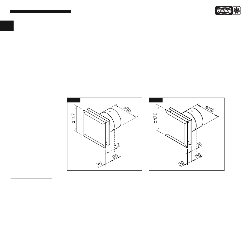
3.4 Abmessungen
MiniVent M1/100/120
MVB Betriebs-/Drehzahlumschalter 0-1-2 Best.Nr. 6091
WES 100 Wandeinbauset Best.Nr. 0717
WES 120 Wandeinbauset Best.Nr. 0486
MF 100 Montageflansch Best.Nr. 6188
TWH 100 Teleskop-Wandhülse Best.Nr. 6352
TWH 120 Teleskop-Wandhülse Best.Nr. 6353
MBR Montageblende Best.Nr. 0281
Dieses Gerät ist auf eine Produktlebensdauer von mindestens 40.000 h, bei S1-Betrieb mit maximaler Leistung in
maximal zulässiger Umgebungstemperatur ausgelegt.
M1/100 M1/120
Abb.2Abb.1
Alle Maße in mm Alle Maße in mm
KAPITEL 4
FUNKTION
4.0 Funktionsbeschreibung M1/100/120
Der M1/100/120 MiniVent Kleinventilator kann mit einem handelsüblichen Lichtschalter in Stufe 1 oder 2 betrieben
werden. Durch die Ansteuerung mit dem Drehzahl Ein/Aus-Schalter MVB (Zubehör) kann der M1/100/120 MiniVent
zweistufig angesteuert werden.
4
Page 7
Montage- und Betriebsvorschrift
KAPITEL 5
REINIGUNG/
DEMONTAGE
GEFAHR
5.0 Reinigung
5.1 Demontage der Fassade
MiniVent M1/100/120
Es sind die in Kapitel 1.2 aufgeführten Sicherheitshinweise zu beachten!
– Vor Beginn der Reinigung ist sicherzustellen, dass der Ventilator allpolig vom Netz getrennt und gegen Wiederein-
schalten gesichert wurde!
– Fassade und sichtbare Gehäuseteile mit einem feuchten Tuch reinigen
– Keine aggressiven, lacklösenden Reinigungsmittel verwenden!
– Hochdruckreiniger oder Strahlwasser ist nicht gestattet!
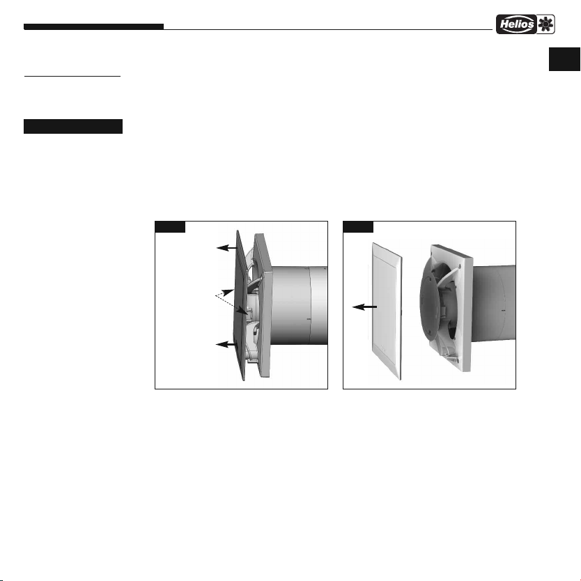
Vorgehensweise:
1. Gerät spannungsfrei schalten und gegen Wiedereinschalten sichern!
2. Durch drücken der Schnapphaken, kann die Fassade
und abgenommen werden (Abb. 3/4).
➊ entriegelt
D
Abb.3
Durch drücken der
2 Schnapphaken
Fassade entriegeln
und abnehmen.
➊
Abb.4
➊
5
Page 8
Montage- und Betriebsvorschrift
D
ACHTUNG
Alle nachfolgenden Informationen und Anweisungen sind nur für eine
autorisierte Elektrofachkraft bestimmt!
MiniVent M1/100/120
KAPITEL 6
INSTALLATION
WARNUNG
6.0 Lieferumfang / Konstruktiver Aufbau
Entnehmen Sie die Liefereinheit erst unmittelbar vor dem Einbau aus dem Karton, um mögliche Beschädigungen
und Verschmutzungen beim Transport sowie auf der Baustelle zu vermeiden.
MiniVent M1/100/120..
➌
➋
Abb.5
➊ Fassade
➋ Anschlussraumabdeckung
➏
➎
➐
inkl. 2x Befestigungsschrauben
➌ Steuerplatine
➍ Kunststoffgehäuse mit Laufrad
➎ Nachleitrad bei eingeschränkter Einbautiefe abnehmbar
➏ Rückluftsperrklappe abnehmbar
➐ Kabeltülle
➑ Montagesatz
2x Schrauben inklusive Dübel für Wandbefestigung
➍
➑
➊
6.1 Vorbereitung zur Wand- oder Deckenmontage (Aufputz)
Es sind die in Kapitel 1.2 aufgeführten Sicherheitshinweise zu beachten!
Der Ventilator wird serienmäßig als komplette Einheit, d.h. anschlussfertig geliefert. Die Montage und Inbetriebnahme
des Ventilators sollte erst nach Abschluss aller anderen Gewerke und nach der Endreinigung erfolgen, um Beschädigungen und Verschmutzung des Lüftungsgerätes zu vermeiden.
Nach Entfernen der Verpackung und vor Montagebeginn sind folgende Punkte zu überprüfen:
– liegen Transportschäden vor,
– gebrochene bzw. verbogene Teile
– Freilauf des Laufrades
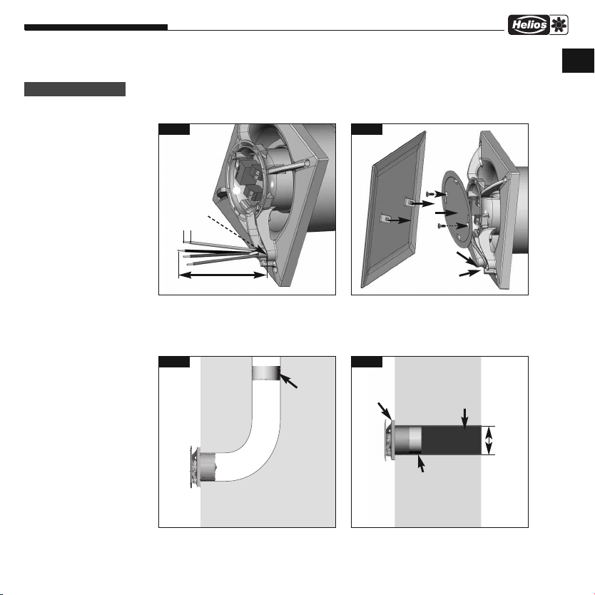
6.2 Installation
Der M1/100/120 MiniVent ist für direkte Wandmontage ausgelegt. Das Gehäuse darf bei der Montage nicht deformiert
oder verzogen werden, es ist auf ebene Beschaffenheit der Einbaufläche zu achten. Die Ventilatoren dürfen nur an ausreichend feste und tragfähige Untergründe, mit hierfür geeigneten Befestigungsmitteln, montiert werden. Eine ausreichende Nachströmung ist zu gewährleisten! Ggf. die Anweisungen aus DIN 1946-6 beachten.
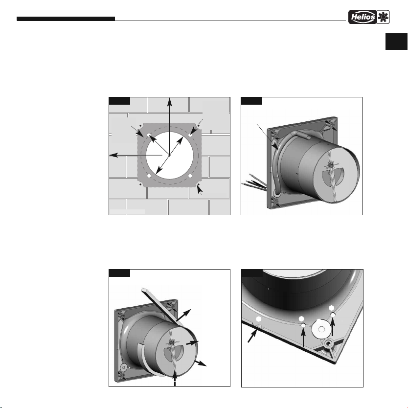
1. Kabelaustritt aus der Wand:
– Die Lage des Kabelaustritts ist im dunklen Bereich variabel (Abb.6).
– Abstand zum Rohrmittelpunkt je nach Kabelaustritt 58/68* mm bei einer variablen Position unter dem Gehäuse.
– Für eine einfache Montage empfiehlt sich ein Austritt wie abgebildet (um jeweils 90° drehbar).
Die optimale Position liegt bei jeweils 45°, wenn sich der Kabelaustritt direkt an der Position der Kabeltülle befindet.
6
Page 9
Montage- und Betriebsvorschrift
MiniVent M1/100/120
– Rohrinnendurchmesser M1/100 = 100 mm bzw. M1/120 = 120 mm
und Abstand zu Raum-Ecken: mindestens 90 mm.
– Bei Aufputzleitungsverlegung, muss die seitliche Aussparung für den Kabeleintritt (Abb.9, Pos
gebrochen werden!
– Das Anschlusskabel ist so zu verwahren, dass bei Wasserbeaufschlagung kein Wasser entlang des Kabels ein-
dringen kann. Das Kabel darf nicht über scharfe Kanten geführt werden!
Abb.6
abelaustritt
K
im dunklen
Bereich beliebig möglich
min. 90 mm
* Type M1/120..
2. Bohrlöcher:
Gehäuse ansetzen Löcher markieren und abbohren und mit mind. zwei Befestigungsschrauben und Dübeln montieren.
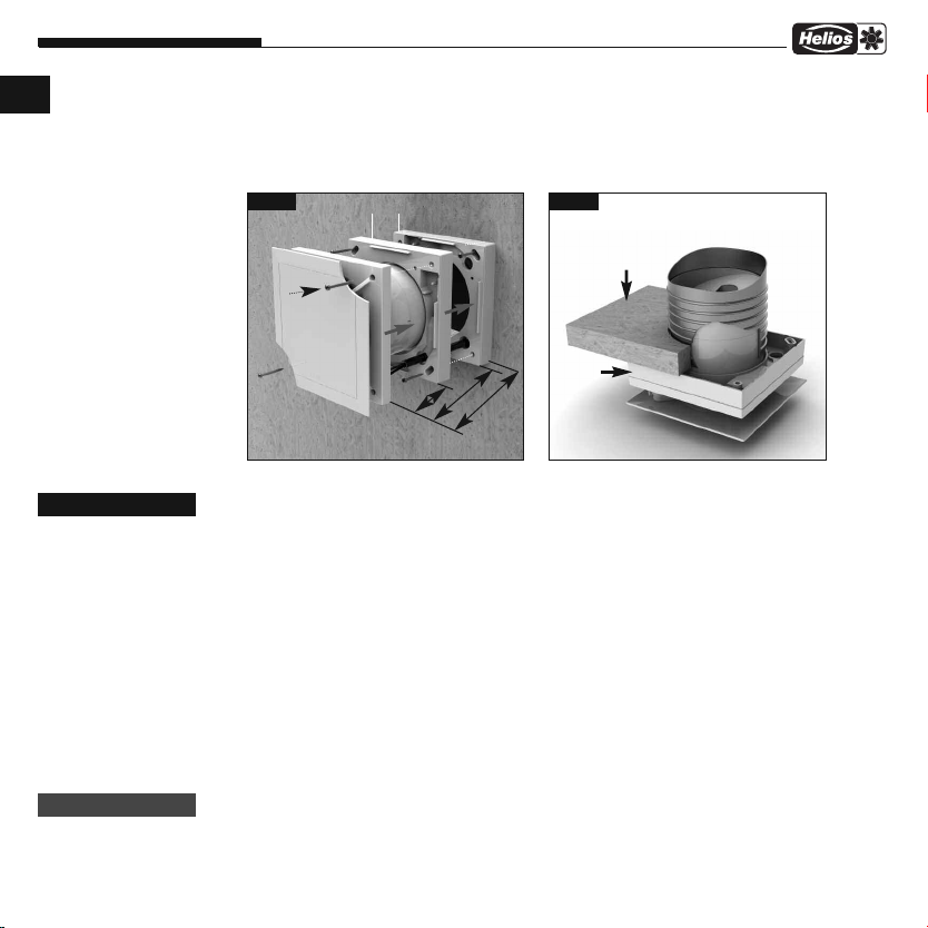
3. Rückluftsperrklappe und Nachleitrad
– Bei Einbau des Gerätes, muss das Nachleitrad senkrecht montiert werden (Abb.8).
Rasterung jeweils um 90° drehbar.
– Vor der Endmontage Schaumstoffstreifen (Lieferumfang) aufkleben (Abb.8)
Abb.8
min. 90 mm
r=58 m
r=68 m
m
m
*
100
Ø
Ø
Bei Einbau des Gerätes, muss das
Nachleitrad
werden (wie dargestellt). Raste-
rung jeweils um 90° drehbar.
➎
senkrecht bei Wandeinbau
Empfohlener
Kabelaustritt
beliebig
0...-360 °,
ideal jeweils
45°
*
mm
m
m
0
2
1
Bohrlöcher
➎ senkrecht montiert
Schaumstoffstreifen
anbringen
oben
Rückluftsperrklappe
abnehmbar
unten
Nachleitrad ➎
abnehmbar
7
Abb.7
Kabelführung unter dem Gehäuse. Kabellänge aus der Wand mindestens
180 mm.
Abb.9
➀
➀ Bei Aufputz-
➏
montage Aussparung
für Kabeleintritt ausbrechen
Kondensatablaufbohrungen
➁
für Deckenmontage.
➁
➂
➀
➁
) im Gehäuse aus
D
Page 10
Montage- und Betriebsvorschrift
D
MiniVent M1/100/120
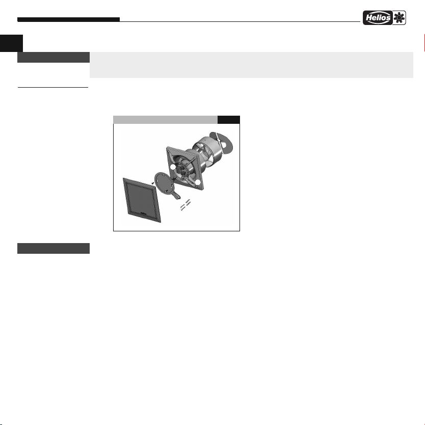
4. Montageflansch MF 100 (Zubehör)
Bei beengten Platzverhältnissen in Decken, in dünnen Wänden sowie in engen Schächten. MF 100 winkelgerecht an
die Wand oder die Decke dübeln (beliebige Anzahl übereinander möglich). Anschließend Ventilator mittels beigefügten Schrauben an MF 100 befestigen (Abb. 10/11). Auch für Montage eines Zugschnurschalters geeignet (Zubehör).
Abb.10
MF 100 aufsteckbar
Abb.11
Decke
GEFAHR
WARNUNG
12
32
E
i
n
Wand
6.3 Elektrischer Anschluss
Es sind die in Kapitel 1.2 aufgeführten Sicherheitshinweise zu beachten!
– Der elektrische Anschluss, bzw. die Erstinbetriebnahme darf nur von einer autorisierten Elektrofachkraft
entsprechend den Angaben in den beiliegenden Anschlussplänen ausgeführt werden.
– Die einschlägigen Normen, Sicherheitsbestimmungen (z. B. DIN VDE 0100) sowie die Technischen Anschlus-
sbedingungen der Energieversorgungsunternehmen sind unbedingt zu beachten!
– Ein allpoliger Netztrennschalter/Revisionsschalter, mit mindestens 3 mm Kontaktöffnung (VDE 0700 T1
7.12.2 / EN 60335-1) ist zwingend vorgeschrieben!
– Netzform, Spannung und Frequenz müssen mit den Angaben des Leistungsschildes übereinstimmen.
6.4 Anschluss der Zuleitung / Inbetriebnahme
– Es ist eine NYM-Leitung einzusetzen, handelsüblicher maximaler Durchmesser 11 mm
– Tülle mit rundem Werkzeug vorstechen oder mit der Zuleitung direkt durchstechen (Abb.9, Pos
– Mantel auf 100 mm entfernen. Drähte 7 mm abisolieren (Abb.12)
– Leitung vorsichtig durch die Tülle schieben
– Drähte im Leitungskanal verlegen und laut Schaltplan (Seite 10) anschließen
– Abdichtung des Anschlusskabels und festen Klemmsitz der Adern prüfen
– Falls bei montierter Zuleitung die Tülle die Mantelleitung nicht gleichmäßig umschließt, muss die Tülle z.B. mit Silikon
zusätzlich abgedichtet werden. Ansonsten erlischt der IP-Schutz
– Das Anschlusskabel ist so zu verwahren, dass bei Wasserbeaufschlagung kein Wasser entlang des Kabels eindrin-
gen kann. Das Kabel darf nicht über scharfe Kanten geführt werden!
– Bestimmungsgemäßen Einsatz des Ventilators überprüfen
– Netzspannung mit Typenschildangabe vergleichen
– Ventilator auf solide Befestigung und fachgerechte elektrische Installation prüfen
baut
52
ie
fe
8
MF 100
)
➂
Page 11
Montage- und Betriebsvorschrift
WARNUNG
MiniVent M1/100/120
– Freilauf des Laufrades prüfen
– Alle Teile, insbesondere Schrauben, auf festen Sitz überprüfen. Schrauben dabei nicht lösen!
– Beim Probelauf den Ventilator auf Vibrationen und Geräusche prüfen
– Stromaufnahme mit Leistungsschildangabe vergleichen
Abb.12 Abb.13
➊
➋
➌
Dichtmasse
7 mm
D
100 mm
- Länge Einzeladern 100 mm
- Abisolierlänge 7 mm
- Mantelleitung bündig mit Kabelkanal abisolieren
6.5 Einbau
Rohrführung
90° Bogen
Montage bei beengten
Platzverhältnissen
Nachleitrad
mit Verschlussklappe
am Rohrende
oder ohne Verwendung des
Nachleitrades
montieren.
9
Anschlussraumabdeckung einhängen
1. Anschlussraumabdeckung ➋in Nut einhängen,
auf Gehäuse drücken und Schrauben fest eindrehen.
2. Fassade
Abb.15Abb.14
Ventilator
Raumseite außen
einschnappen.
➊
WES 1.. oder
TWH 1..
Nachleitrad mit
Verschlussklappe
Standard Einbau
Kernlochbohrung
M1/100 =
Ø 115 mm
M1/120 =
Ø 130 mm
Page 12

Montage- und Betriebsvorschrift
12
LN
M1/...
1
2
a) Rückspg.! siehe MBV
L
L
L
N
MVB, Art. Nr. 6091.002
0
I
a) a)
12
LN
N
L
M1/...
a)a)
SS-915
1
2
a) Rückspg.! siehe MBV
D
WARNUNG
KAPITEL 7
FUNKTION FÜR
INSTALLATEUR
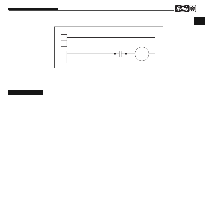
6.6 Betrieb
7.0 Funktionsbeschreibung M1/100/120 (Standardmodell)
7.1 Schaltplanübersicht für M1/100/120 (Standardmodell)
MiniVent M1/100/120
Es sind die in Kapitel 1.2 aufgeführten Sicherheitshinweise zu beachten!
Zur Gewährleistung der einwandfreien Funktion des Ventilators, ist regelmäßig Folgendes zu prüfen:
– Auftreten von Staub- oder Schmutzablagerungen im Gehäuse bzw. am Motor und Laufrad
– Freilauf des Laufrades
– Auftreten von übermäßigen Schwingungen und Geräuschen
Bei Problemen mit einem der oben aufgeführten Punkte, ist eine Wartung nach den Anweisungen aus Kapitel 8 durch
zuführen.
Der M1/100/120 MiniVent Kleinventilator kann mit einem handelsüblichen Lichtschalter in Stufe 1 oder 2 betrieben
werden.
Mit dem Drehzahl Ein-/Ausschalter MVB (Zubehör nur für M1/100/120) kann der M1/100 mit zwei Leistungsstufen
3
/h) oder der M1/120 mit zwei Leistungsstufen (150/170 m3/h) betrieben werden.
(75/90 m
Fußnoten:
a) Bei Anschluss der Klemme
1 oder 2, liegt jeweils an der
anderen nicht geschalteten
Klemme eine Rückspannung an.
Raumbeleuchtung oder
Glimmlampen zur Betriebsanzeige, sind nur über
zweipoligen Schalter anzuschließen.
M1/100/120 mit MVB
10
SS-930
Page 13
Montage- und Betriebsvorschrift
M1~
1
2
L
N
MiniVent M1/100/120
M1/100/120 Prinzip
75 m3/h / 150 m3/h
90 m
3
/h / 170 m3/h
D
SS-921
KAPITEL 8
INSTANDHALTUNG/
WARTUNG
GEFAHR
8.0 Instandhaltung und Wartung
Es sind die in Kapitel 1.2 aufgeführten Sicherheitshinweise zu beachten!
– Vor allen Arbeiten ist sicherzustellen, dass der Ventilator allpolig vom Netz getrennt und gegen Wiedereinschalten
gesichert wurde!
– Grundsätzlich sind die Geräte wartungsfrei, es ist keine Benutzer-Wartung vorgesehen. Alle dennoch notwendigen
Wartungsarbeiten sind von Elektrofachkräften durchzuführen!
– Übermäßige Ablagerungen von Schmutz, Staub, Fetten u.a.m. auf Laufrad, Motor und vor allem zwischen Gehäuse
und Laufrad sind unzulässig, da sie zu Unwucht im Laufrad, Überhitzung des Motors oder zum Blockieren des Laufrads führen können. In solchen Fällen ist das Gerät zu reinigen.
– Im Falle längeren Stillstands ist bei Wiederinbetriebnahme eine Wartung durchzuführen.
Zu prüfen sind:
• sichere Befestigung des Ventilators am Untergrund / an der Anlage, im Zweifelsfall erneuern
• Schmutzablagerungen entfernen
• mechanische Beschädigungen, Gerät stilllegen, beschädigte Teile austauschen
• fester Sitz der Schraubverbindungen, Schrauben dabei nicht lösen!
• Gehäusebeschaffenheit (Risse, Versprödung des Kunststoffs)
• Freilauf des Laufrads, läuft das Laufrad nicht frei, Störungsursachen 8.1 beachten
• Lagergeräusche
• Vibrationen – siehe Störungsursachen 8.1
• Stromaufnahme entsprechend dem Typenschild – siehe Störungsursachen 8.1
11
Page 14
Montage- und Betriebsvorschrift
D
WARNUNG
WARNUNG
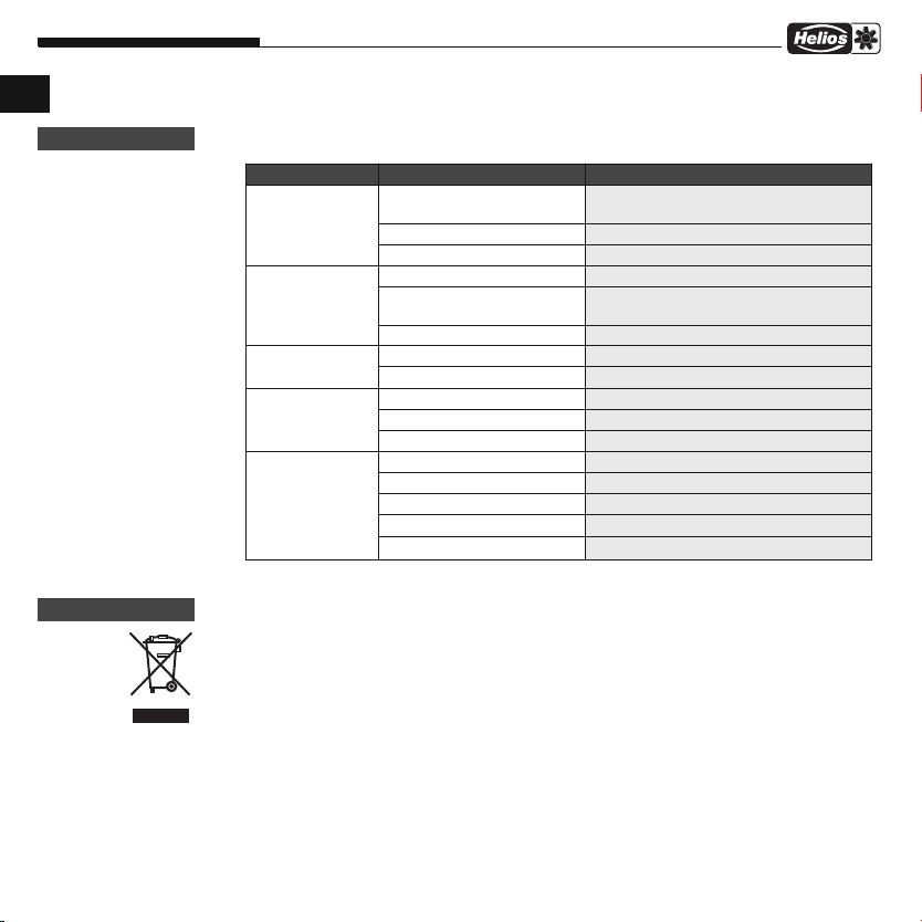
8.1 Störungsursachen
8.2 Stilllegen und Entsorgen
MiniVent M1/100/120
Es sind die in Kapitel 1.2 aufgeführten Sicherheitshinweise zu beachten!
Fehler
Ventilator startet
nicht
Sicherung löst aus
Vibrationen
Anormale Geräusche
Ventilator bringt die
Leistung (Drehzahl)
nicht
Es sind die in Kapitel 1.2 aufgeführten Sicherheitshinweise zu beachten!
Bauteile und Komponenten des Ventilators, die ihre Lebensdauer erreicht haben, z.B. durch Verschleiß, Korrosion,
mechanische Belastung, Ermüdung und / oder durch andere, nicht unmittelbar erkennbare Einwirkungen, sind nach
erfolgter Demontage entsprechend den nationalen und internationalen Gesetzen und Vorschriften fach- und sachgerecht zu entsorgen. Das Gleiche gilt auch für im Einsatz befindliche Hilfsstoffe wie Öle und Fette oder sonstige Stoffe.
Die bewusste oder unbewusste Weiterverwendung verbrauchter Bauteile wie z.B. Laufräder, Wälzlager, Keilriemen,
etc. kann zu einer Gefährdung von Personen, der Umwelt sowie von Maschinen und Anlagen führen. Die entsprechenden, vor Ort geltenden Betreibervorschriften sind zu beachten und anzuwenden.
Ursachen
– keine Spannung
– Laufrad blockiert
– Motor blockiert
– Windungsschluss im Motor
– Zuleitung bzw. Anschluss
beschädigt
– falsch angeschlossen
– Verschmutzung
– befestigungsbedingte Resonanz
– schleifendes Laufrad
– Lagerschäden
– mechanische Beschädigung
– Unzureichende Luftförderung
– falsche Spannung
– Lagerschäden
– Verschmutzung
– unzureichende Nachströmung
Lösung
Netzspannung prüfen
Anschluss nach Schaltplan überprüfen
Blockade lösen, reinigen, ggf. Laufrad ersetzen
Helios Kundendienst kontaktieren
Helios Kundendienst kontaktieren
Teile erneuern, ggf. Motor ersetzen
(Helios Kundendienst kontaktieren)
Anschluss überprüfen, ändern
reinigen
Befestigung prüfen bzw. ausbessern
Laufrad reinigen, ggf. ersetzen
Helios Kundendienst kontaktieren
Wartung durchführen
Zu- und Abströmung prüfen/freihalten
Anschluss prüfen/ändern
Helios Kundendienst kontaktieren
reinigen
Nachströmungsöffnungen erweitern
12
Page 15

Montage- und Betriebsvorschrift
Notizen:
MiniVent M1/100/120
D
13
Page 16

Als Referenz am Gerät griffbereit aufbewahren! Druckschrift-Nr.
Please keep this manual for reference with the unit! Print-No.:
Conservez cette notice à proximité de l’apapreil! N° Réf.
Service / Information
D HELIOS Ventilatoren GmbH & Co · Lupfenstraße 8 · 78056 VS-Schwenningen
A HELIOS Ventilatoren · Postfach 854 · Siemensstraße 15 · 6023 Innsbruck
F HELIOS Ventilateurs · Le Carré des Aviateurs · 157 av. Charles Floquet · 93155 Le Blanc Mesnil Cedex
CH HELIOS Ventilatoren AG · Tannstrasse 4 · 8112 Otelfingen
GB HELIOS Ventilation Systems Ltd. · 5 Crown Gate · Wyncolls Road · Severalls Industrial Park · Colchester · Essex · CO4 9HZ
19050.005/02.15
www.heliosventilatoren.de
Page 17

INSTALLATION AND OPERATING INSTRUCTIONS NO. 19050.005
IP 45
Kleinlüfter - Mini fan - Mini ventilateur
Helios MiniVent
M1/100/120
- mit zwei Leistungsstufen
- equipped with 2 speeds
- à 2 vitesses de fonctionnement
UK
Page 18

ENGLISH
Table of contents
CHAPTER 1. GENERAL INFORMATION . . . . . . . . . . . . . . . . . . . . . . . . . . . . . . . . . . . . . . . . . . . . . . . . . . . . . . . .Page 1
1.0 Important information . . . . . . . . . . . . . . . . . . . . . . . . . . . . . . . . . . . . . . . . . . . . . . . . . . . . . . . . . . . . . . . . . .Page 1
1.1 Warning instructions . . . . . . . . . . . . . . . . . . . . . . . . . . . . . . . . . . . . . . . . . . . . . . . . . . . . . . . . . . . . . . . . . . .Page 1
1.2 Safety instructions . . . . . . . . . . . . . . . . . . . . . . . . . . . . . . . . . . . . . . . . . . . . . . . . . . . . . . . . . . . . . . . . . . . . .Page 1
1.3 Warranty claims - exclusion of liability . . . . . . . . . . . . . . . . . . . . . . . . . . . . . . . . . . . . . . . . . . . . . . . . . . . . . .Page 2
1.4 Certificates - guidelines . . . . . . . . . . . . . . . . . . . . . . . . . . . . . . . . . . . . . . . . . . . . . . . . . . . . . . . . . . . . . . . . .Page 2
1.5 Shipping . . . . . . . . . . . . . . . . . . . . . . . . . . . . . . . . . . . . . . . . . . . . . . . . . . . . . . . . . . . . . . . . . . . . . . . . . . . .Page 2
1.6 Receipt . . . . . . . . . . . . . . . . . . . . . . . . . . . . . . . . . . . . . . . . . . . . . . . . . . . . . . . . . . . . . . . . . . . . . . . . . . . . .Page 2
1.7 Storage . . . . . . . . . . . . . . . . . . . . . . . . . . . . . . . . . . . . . . . . . . . . . . . . . . . . . . . . . . . . . . . . . . . . . . . . . . . . .Page 2
1.8 Application . . . . . . . . . . . . . . . . . . . . . . . . . . . . . . . . . . . . . . . . . . . . . . . . . . . . . . . . . . . . . . . . . . . . . . . . . .Page 2
1.9 Performance data . . . . . . . . . . . . . . . . . . . . . . . . . . . . . . . . . . . . . . . . . . . . . . . . . . . . . . . . . . . . . . . . . . . . .Page 3
1.10 Noise data . . . . . . . . . . . . . . . . . . . . . . . . . . . . . . . . . . . . . . . . . . . . . . . . . . . . . . . . . . . . . . . . . . . . . . . . . .Page 3
CHAPTER 2. GENERAL OPERATING INSTRUCTIONS . . . . . . . . . . . . . . . . . . . . . . . . . . . . . . . . . . . . . . . . . . . .Page 3
2.0 Personnel qualification . . . . . . . . . . . . . . . . . . . . . . . . . . . . . . . . . . . . . . . . . . . . . . . . . . . . . . . . . . . . . . . . . .Page 3
2.1 Protection against contact . . . . . . . . . . . . . . . . . . . . . . . . . . . . . . . . . . . . . . . . . . . . . . . . . . . . . . . . . . . . . .Page 3
2.2 Motor protection device . . . . . . . . . . . . . . . . . . . . . . . . . . . . . . . . . . . . . . . . . . . . . . . . . . . . . . . . . . . . . . . .Page 3
CHAPTER 3. TECHNICAL DATA/DIMENSIONS . . . . . . . . . . . . . . . . . . . . . . . . . . . . . . . . . . . . . . . . . . . . . . . . . .Page 3
3.0 Type overview MiniVent M1/1... . . . . . . . . . . . . . . . . . . . . . . . . . . . . . . . . . . . . . . . . . . . . . . . . . . . . . . . . . . .Page 3
3.1 Technical data . . . . . . . . . . . . . . . . . . . . . . . . . . . . . . . . . . . . . . . . . . . . . . . . . . . . . . . . . . . . . . . . . . . . . . . .Page 3
3.2 Accessories . . . . . . . . . . . . . . . . . . . . . . . . . . . . . . . . . . . . . . . . . . . . . . . . . . . . . . . . . . . . . . . . . . . . . . . . .Page 4
3.3 Product service life . . . . . . . . . . . . . . . . . . . . . . . . . . . . . . . . . . . . . . . . . . . . . . . . . . . . . . . . . . . . . . . . . . . .Page 4
3.4 Dimensions . . . . . . . . . . . . . . . . . . . . . . . . . . . . . . . . . . . . . . . . . . . . . . . . . . . . . . . . . . . . . . . . . . . . . . . . . .Page 4
CHAPTER 4. FUNCTION . . . . . . . . . . . . . . . . . . . . . . . . . . . . . . . . . . . . . . . . . . . . . . . . . . . . . . . . . . . . . . . . . . . .Page 4
4.0 Functional description M1/100/120 . . . . . . . . . . . . . . . . . . . . . . . . . . . . . . . . . . . . . . . . . . . . . . . . . . . . . . . .Page 4
CHAPTER 5. CLEANING/DISMANTLING . . . . . . . . . . . . . . . . . . . . . . . . . . . . . . . . . . . . . . . . . . . . . . . . . . . . . . .Page 5
5.0 Cleaning . . . . . . . . . . . . . . . . . . . . . . . . . . . . . . . . . . . . . . . . . . . . . . . . . . . . . . . . . . . . . . . . . . . . . . . . . . . .Page 5
5.1 Dismantling of the facia . . . . . . . . . . . . . . . . . . . . . . . . . . . . . . . . . . . . . . . . . . . . . . . . . . . . . . . . . . . . . . . . .Page 5
CHAPTER 6. INSTALLATION . . . . . . . . . . . . . . . . . . . . . . . . . . . . . . . . . . . . . . . . . . . . . . . . . . . . . . . . . . . . . . . . .Page 6
6.0 Scope of delivery/Design . . . . . . . . . . . . . . . . . . . . . . . . . . . . . . . . . . . . . . . . . . . . . . . . . . . . . . . . . . . . . . . .Page 6
6.1 Preparation for wall or ceiling installation (surface mounted) . . . . . . . . . . . . . . . . . . . . . . . . . . . . . . . . . . . . .Page 6
6.2 Installation . . . . . . . . . . . . . . . . . . . . . . . . . . . . . . . . . . . . . . . . . . . . . . . . . . . . . . . . . . . . . . . . . . . . . . . . . . .Page 6
6.3 Electrical connection . . . . . . . . . . . . . . . . . . . . . . . . . . . . . . . . . . . . . . . . . . . . . . . . . . . . . . . . . . . . . . . . . . .Page 8
6.4 Connection of the supply line / Start-up . . . . . . . . . . . . . . . . . . . . . . . . . . . . . . . . . . . . . . . . . . . . . . . . . . . .Page 8
6.5 Mounting . . . . . . . . . . . . . . . . . . . . . . . . . . . . . . . . . . . . . . . . . . . . . . . . . . . . . . . . . . . . . . . . . . . . . . . . . . . .Page 9
6.6 Operation . . . . . . . . . . . . . . . . . . . . . . . . . . . . . . . . . . . . . . . . . . . . . . . . . . . . . . . . . . . . . . . . . . . . . . . . . .Page 10
CHAPTER 7. FUNCTION FOR INSTALLER . . . . . . . . . . . . . . . . . . . . . . . . . . . . . . . . . . . . . . . . . . . . . . . . . . . . .Page 10
7.0 Functional description for M1/100/120 . . . . . . . . . . . . . . . . . . . . . . . . . . . . . . . . . . . . . . . . . . . . . . . . . . . .Page 10
CHAPTER 8. SERVICING AND MAINTENANCE . . . . . . . . . . . . . . . . . . . . . . . . . . . . . . . . . . . . . . . . . . . . . . . . .Page 11
8.0 Servicing and maintenance . . . . . . . . . . . . . . . . . . . . . . . . . . . . . . . . . . . . . . . . . . . . . . . . . . . . . . . . . . . . .Page 11
8.1 Fault causes . . . . . . . . . . . . . . . . . . . . . . . . . . . . . . . . . . . . . . . . . . . . . . . . . . . . . . . . . . . . . . . . . . . . . . . .Page 12
8.2 Standstill and disposal . . . . . . . . . . . . . . . . . . . . . . . . . . . . . . . . . . . . . . . . . . . . . . . . . . . . . . . . . . . . . . . .Page 12
Page 19

Installation and Operation Instructions
CHAPTER 1
GENERAL INFORMATION
DANGER
WARNING
CAUTION
1.0 Important information
In order to ensure complete and effective operation and for your own safety, all of the following instructions should be
read carefully and observed.
This document should be regarded as part of the product and as such should be kept accessible and durable to ensure the safe operation of the fan. All plant-related safety regulations must be observed.
1.1 Warning instructions
The accompanying symbols are safety-relevant prominent warning symbols. All
safety regulations and/or symbols in this document must be absolutely adhered
to, so that any risks of injury and dangerous situations are avoided!
1.2 Safety instructions
Special regulations apply for use, connection and operation; consultation is required in
case of doubt. Further information can be found in the relevant standards and legal
DANGER
texts.
With regard to all work on the fan, the generally applicable safety at work and
accident prevention regulations must be observed!
• All electrical work, as well as installation, servicing and maintenance of the fan
must only be carried out by qualified electricians!
• The following must be observed before all cleaning, installation, servicing and
maintenance work or before opening the terminal compartment:
– Isolate the device from the mains power supply and secure against being
switched on again!
– The rotating parts must first come to a standstill!
– Once the rotating parts come to a standstill, a waiting time of 3 min. must be
observed, as dangerous voltages may be present due to internal capacitors even
after disconnection from the mains!
• All plant-related safety regulations must be observed!
If applicable, further country-specific regulations must also be observed!
• A uniform inflow and free outlet must be ensured!
• When using a vented fire place (chimney) in a ventilated room, there must be
sufficient supply air for all operating conditions (consult chimney sweep). The
current locally applicable regulations and laws must be observed!
• MiniVent M1/100/120 mini fans can be used by children over the age of 8 as
well as persons with physical, sensory, or mental disabilities or lack of experience and knowledge, if they are supervised or instructed with regard to the safe
use of the unit and they understand the resulting risks. Children must not play
with the unit. Cleaning or user maintenance must not be carried out by unsupervised children.
MiniVent M1/100/120
UK
1
Page 20

Installation and Operation Instructions
UK
1.3 Warranty claims – exclusion of liability
IMPORTANT
NOTE
NOTE
NOTE
1.4 Certificates - guidelines
☞
1.5 Shipping
1.6 Receipt
1.7 Storage
1.8 Application
☞
☞
☞
MiniVent M1/100/120
All versions of this documentation must be observed, otherwise the warranty shall cease to apply. The same applies
to liability claims against Helios. The use of accessory parts, which are not recommended or offered by Helios, is not
permitted. Any possible damages are not covered by the warranty. Changes and modifications to the unit are not permitted and lead to a loss of conformity, and any warranty and liabilit y shall be excluded in this case.
If the product is installed correctly and used to its intended purpose, it conforms to all applicable EU guidelines at its
date of manufacture.
The fan is packed ex works in such a way that it is protected against normal transport strain. Carry out the shipping
carefully. It is recommended to leave the fan in the original packaging.
The shipment must be checked for damage and correctness immediately upon delivery. If there is any damage,
promptly report the damage with the assistance of the transport company. If complaints are not made within the agreed period, any claims could be lost.
When storing for a prolonged time, the following steps are to be taken to avoid damaging influences: Motor protection by dry, airtight and dust-proof packaging (plastic bag with desiccant and humidity indicators). Vibration-free, water-tight and constant-temperature storage at a temperature in the range -20 °C to +40 °C.
In case of a storage period of more than three months or motor standstill, maintenance must be carried out before
start-up according to chapter 4. In case of reshipment (above all, over longer distances; e.g. by sea), it must be
checked whether the packaging is suitable for the form and route of transport. Damages due to improper transportation, storage or putting into operation are not liable for warranty.
– Normal use:
The MiniVent M1/100/120 mini fans are suitable for conveying normal or slightly dusty (particle size < 10 µm), less aggressive and humid air, in moderate climates and in the range of their performance curves, see Helios sales documents / internet. Operation is only admissible with fixed installation within buildings. The maximum admissible media
and ambient temperature is 40 °C. MiniVent M1/150 ... mini fans correspond to protection category IP45, protection
class II and may be installed in area 1 wet rooms according to VDE 0100 part 701.
– Reasonably foreseeable misuse:
The fans are not suitable for operation under difficult conditions, such as high levels of humidity, aggressive media,
long standstill periods, heavy contamination, excessive loads due to climatic, technical or electronic influences. The
same applies for the mobile use of fans (vehicles, aircraft, ships, etc.). Usage under these conditions is only possible
with release approval from Helios, as the standard version is not suitable in this case.
– Improper, prohibited use:
Any use other than the intended use is not permitted! The conveying of solid matter or solid matter content > 10µm
in air and liquid is not permitted. Transport media, which affect the materials of the fan, and abrasive media are not
permitted. Use in explosive atmospheres is not permitted!
2
Page 21

Installation and Operation Instructions
1.9 Performance data
The unit type plate gives an indication of the mandatory electrical values; which must be coordinated with the local
supply network. The fan performances* were established on a test stand according to DIN EN ISO 5801.
1.10 Noise data
Noise data that refers to certain distances apply to free field conditions. With regard to installation, the sound pressure level can differ significantly from the catalogue data, as it is highly dependent on the installation conditions, i.e. on
the absorption capability of the room and the room size among other factors.
CHAPTER 2
GENERAL OPERATING
INSTRUCTIONS
CHAPTER 3
TECHNICAL DATA /
DIMENSIONS
2.0 Personnel qualification
The electrical connection and start-up as well as installation, servicing and maintenance of the fan
must only be carried out by qualified electricians.
– MiniVent M1/100/120 mini fans can be used by children over the age of 8 as well as persons with physical, sensory,
or mental disabilities or lack of experience and knowledge, if they are supervised or instructed with regard to the safe use of the unit and they understand the resulting risks. Children must not play with the unit. Cleaning or user maintenance must not be carried out by unsupervised children.
2.1 Protection against contact
MiniVent M1/100/120 mini fans do not require a protection guard, as they meet the requirements of DIN EN 603352-80 section 20.101.
2.2 Motor protection device
The motors of the MiniVent M1/100/120 are equipped with thermo contacts, which are wired in series with the winding, and which automatically switch off and on again after cooling.
3.0 Type overview MiniVent M1/1..
M1/100 equipped with two speeds Ref.No. 6171
M1/120 equipped with two speeds Ref.No. 6360
3.1 Technical data
M1/100
Impeller Ø [mm] 92 Electrical supply line NYM-O 3 x 1.5 mm²
Alternating current 1~ Protection category IP 45 (water jet protection)
Voltage/frequency 230 V, 50 Hz Protection class II
Power consumption [W] 9/5 Weight approx. [kg] 0,8
Rated current [mA] 0.06/0.04 Speed [1/min] 2650/2250
Flow volume [m
M1/120
Impeller Ø [mm] 111 Electrical supply line NYM-O 3 x 1.5 mm²
Alternating current 1~ Protection category IP 45 (water jet protection)
Voltage/frequency 230 V, 50 Hz Protection class II
Power consumption [W] 13/10 Weight approx. [kg] 1,05
Rated current [mA] 0.09/0.08 Speed [1/min] 2350/2050
Flow volume [m
MiniVent M1/100/120
3
/h] 90/75
3
/h] 170/150
UK
3
Page 22

Installation and Operation Instructions
UK
3.2 Accessories
3.3 Product service life
3.4 Dimensions
MiniVent M1/100/120
MVB Operating/speed switch 0-1-2 Ref.No. 6091
WES 100 Wall installation kit Ref.No. 0717
WES 120 Wall installation kit Ref.No. 0486
MF 100 Mounting flange Ref.No. 6188
TWH 100 Telescopic wall sleeve Ref.No. 6352
TWH 120 Telescopic wall sleeve Ref.No. 6353
MBR Mounting cover strip Ref.No. 0281
This unit is designed for a product service life of at least 40,000 h, in case of S1 operation with maximum power in the
maximum permissible ambient temperature.
M1/100 M1/120
fig.2fig.1
All dimensions in mm All dimensions in mm
CHAPTER 4
FUNCTION
4.0 Functional description M1/100/120
The M1/100/120 MiniVent mini fan can be selectively operated with a commercially available light switch in stage 1 or
stage 2. By controlling the speed with the on/off switch MVB (Accessories), the M1/100/120 MiniVent can be used in
two settings.
4
Page 23

Installation and Operation Instructions
CHAPTER 5
CLEANING/
DISMANTLING
DANGER
5.0 Cleaning
The safety instructions in chapter 1.2 must be observed!
– Before cleaning, isolate the fan from the mains power supply and secure against being switched on again!
– Clean facia and visible casing parts with a damp cloth
– Do not use aggressive, paint-damaging cleaning agents!
– High pressure cleaners or jet water is not permitted!
5.1 Dismantling of the facia
Procedure:
1. Isolate fan from mains power supply and secure against being switched on again!
2. By pressing the snap-in hooks, the facia
and removed (fig. 3/4).
MiniVent M1/100/120
UK
➊ can be unlocked
fig.3
Unlock and remove
the facia by pressing
the 2 snap-in hooks.
➊
fig.4
➊
5
Page 24

Installation and Operation Instructions
UK
ATTENTION
All subsequent information and instructions are intended solely for
authorised electricians!
MiniVent M1/100/120
CHAPTER 6
INSTALLATION
WARNING
6.0 Scope of delivery/Design
Leave the delivery unit in its box until installation. Check that the fan is in good condition and has not been damaged
in transit.
MiniVent M1/100/120..
➌
➋
fig.5
➊ Facia
➋ Terminal compartment cover
➏
➎
➐
incl. 2x fastening screws
➌ Control board
➍ Plastic casing with impeller
➎ Guide vane removable at reduced installation depth
➏ Back draught shutter removable
➐ Cable grommet
➑ Assembly kit
2x screws including plugs for wall mounting
➍
➑
➊
6.1 Preparation for wall or ceiling installation (surface mounted)
The safety instructions in chapter 1.2 must be observed!
The fan is delivered as a complete unit, i.e. ready for connection, as standard. The installation and start-up of the fan
should take place after the completion of all other works and after the final cleaning, in order to prevent damage and
contamination of the ventilation unit.
After the removal of packaging and the start of installation, the following points must be checked:
– is there any transport damage,
– broken or bent parts
– freewheeling of the impeller
6.2 Installation
The M1/100/120 MiniVent is designed for direct wall installation. The housing must not be deformed or warped during installation, and the flat structure of the installation surface must be ensured. The fans must only be installed on
sufficiently solid and stable subsurfaces with suitable fastening materials. Sufficient backflow must be ensured! If applicable, observe instructions in DIN 1946-6.
1. Cable exit from the wall:
– The location of the cable outlet varies in the dark area (fig.6).
– Distance to the duct centre depending on cable exit 58/68* mm with a variable position under the casing.
– For a simple assembly an exit is recommended as shown (turnable by 90° in each case).
The optimal position is 45° each if the cable exit is directly at the position of the cable grommet.
6
Page 25

Installation and Operation Instructions
– Duct inside diameter M1/100 = 100 mm or M1/120 = 120 mm
and distance to room corners: at least 90 mm.
– With regard to surface mounted cabling, the side entry knockout for the cable (fig.9, Pos
broken out!
– The connection cable and the control line must be stored so that no water can get in along the cable in case of water exposure. The cables must not be placed over sharp edges!
fig.6
able exit
C
possible as
required in
dark area
min. 90 mm
* Type M1/120..
2. Drill holes:
Set casing against the wall, mark the holes and drill. Fasten with at least 2 screws and plugs.
3. Back draught shutter and guide van
– When installing the device, the guide vane must be mounted vertically (fig. 8).
Snaps into place every 90° rotation.
– Affix the rubber foam (scope of delivery) before final assembly (fig.8)
fig.8
MiniVent M1/100/120
Recommended cable
exit optional
min. 90 mm
r=58 m
r=68 m
m
m
*
100
Ø
Ø
When installing the device, the guide vane
➎ must be mounted verti-
cally (as depicted). Snaps into place
➎
vertical for wall installation
0...-360 °,
ideally 45°
*
mm
m
m
0
2
1
drill holes
every 90° rotation.
Affix the rub-
ber foam
top
Back draught
shutter
removable
bottom
Guide vane ➎
removable
7
fig.7
Cable routing under the casing. Cable
length from wall at least
180 mm.
fig.9
➀
➀ Break out entry
➏
knockout for cable for
wall mounting
Condensate drain holes for
➁
ceiling suspension.
UK
) in the casing must be
➀
➁
➁
➂
Page 26

Installation and Operation Instructions
UK
MiniVent M1/100/120
4. Mounting flange MF 100 (Accessories)
If there are space restrictions in ceilings, in thin walls and in narrow shafts. Attach MF 100 to the wall or ceiling at a
suitable angle (any number possible). Then fasten the fan to the MF 100 with the provided screws (fig. 10/11). Also
suitable for mounting a pull-cord switch (Accessories).
fig.10
MF 100 snap-on
fig.11
Ceiling
DANGER
WARNING
12
32
i
nst
all
de
Wall
6.3 Electrical connection
The safety instructions in chapter 1.2 must be observed!
– The electrical connection and initial start-up are to be carried out in accordance with the relevant wiring dia
gram and are only to be carried out by a certified electrician.
– All relevant standards, safety regulations (e.g. DIN VDE 0100), as well as the technical connection conditions
of energy suppliers are to be adhered to!
– A multipole mains section switch/isolator, with a minimum contact opening of 3 mm (VDE 0700 T1
7.12.2 / EN 60335-1) is mandatory!
– Network configuration, voltage and frequency must be consistent with the rating plate information.
6.4 Connection of the supply line / Start-up
– A commercially available NYM line must be used, maximum diameter 11 mm
– Pre-pierce grommet with round tool or pierce directly with supply line (fig.9, Pos
– Remove sheath to100 mm. Strip wires to 7 mm (fig.12)
– Carefully push cable through the grommet
– Place wires in the cable channel and connect according to wiring diagram (page 10)
– Check the waterproofing of the connection cable and tight clamping of the strands
– If the grommet does not evenly enclose the sheathed cable once the supply line is installed, the grommet must be
additionally sealed, e.g. with Silicone N. Otherwise, the IP protection will expire
– The connection cable and the control line must be stored so that no water can get in along the cable in case of
water exposure. The cables must not be placed over sharp edges!
– Check designated use of fan
– Compare mains voltage to rating plate data
– Check fan for solid mounting and professional electrical installation
pth
52
a
ti
on
8
MF 100
)
➂
Page 27

Installation and Operation Instructions
WARNING
– Check freewheeling of the impeller
– Check all parts for tightness, particularly screws, protection guards. Do not loosen screws in the process!
– Check fan for vibration and noise during test run
– Compare power consumption to rating plate data
fig.12 fig.13
MiniVent M1/100/120
UK
➊
➋
100 mm
Duct channel
90° bend
➌
Sealing
compound
7 mm
- Length of single conductors 100 mm
- Stripping length 7 mm
- Strip sheathed cable flush with cable duct
6.5 Mounting
Assembly in cramped
Mount guide
vane with
back draught
shutter at the
end of the
duct or just
omit it.
conditions
9
Attach terminal
compartment cover
1. Align terminal compartment cover ➋with groove,
attach and screw to casing.
2. Then snap-in facia
fig.15fig.14
Fan
Room side
.
➊
WES 1.. or
TWH 1..
Guide vane with
back draught
shutter
Standard installation
Core drill
hole
M1/100 =
Ø 115 mm
M1/120 =
Ø 130 mm
Outside
Page 28

Installation and Operation Instructions
12
LN
M1/...
1
2
a) Rückspg.! siehe MBV
L
L
L
N
MVB, Art. Nr. 6091.002
0
I
a) a)
12
LN
N
L
M1/...
a)a)
SS-915
1
2
a) Rückspg.! siehe MBV
UK
WARNING
CHAPTER 7
FUNCTION FOR
INSTALLER
6.6 Operation
7.0 Functional description M1/100/120 (Standard model)
two settings (75/90 m
7.1 Circuit diagram overview for M1/100/120 (Standard model)
MiniVent M1/100/120
The safety instructions in chapter 1.2 must be observed!
In order to ensure the smooth functioning of the fan, the following must be checked on a regular basis:
– Appearance of dust or contaminant deposits in the housing or on the motor and impeller
– Freewheeling of the impeller
– Occurrence of excessive vibration and noise
In case of problems with one of the aforementioned points, maintenance must be carried out according to the
instructions in chapter 8.
The M1/100/120 MiniVent mini fan can be selectively operated with a commercially available light switch in stage 1
or stage 2.
By controlling the speed with the on/off switch MVB (Accessories only for M1/100/120), the M1/100 can be used in
3
/h) or the M1/120 can be used in two settings (150/170 m3/h).
Footnotes:
a) With regard to the connec-
tion of terminal 1 or 2, there
is reverse voltage at the
other respective disconnected terminal.
Room lighting or glow
lamps for operating displays, must only be connected via bipolar switch.
M1/100/120 with MVB
10
SS-930
Page 29

Installation and Operation Instructions
M1~
1
2
L
N
M1/100/120 principle
MiniVent M1/100/120
75 m3/h / 150 m3/h
3
90 m
/h / 170 m3/h
UK
SS-921
CHAPTER 8
SERVICING/
MAINTENANCE
DANGER
8.0 Servicing and maintenance
The safety instructions in chapter 1.2 must be observed!
– Before any work, isolate the fan from the mains power supply and secure against being switched on again!
– The units are basically maintenance-free, there is no provision for user-maintenance. Nevertheless, all necessary
maintenance work must be carried out by trained electricians!
– Excessive deposits of dirt, dust, grease, etc. on the impeller, motor, protection guard and, above all, between the
housing and the impeller, are not permitted, as these can lead to an unbalance in the impeller, overheating of the
motor or the blocking of the impeller.
– In cases of longer periods of standstill, maintenance must be carried out when the unit is restarted.
The following must be checked:
• Secure mounting of the fan to the subsurface / system, replace in case of doubt
• Remove contaminant deposits
• Mechanical damage, decommission unit, replace damaged parts
• Tightness of screw connections, do not loosen screws in the process!
• Housing surface coating (e.g. rust, paint defects)
• Freewheeling of the impeller -> Is the impeller not running freely- see Fault causes8.1
• Bearing noises
• Vibrations– see Fault causes 8.1
• Power consumption according to type plate - see Fault causes 8.1
11
Page 30

Installation and Operation Instructions
UK
WARNING
WARNING
8.1 Fault causes
8.2 Standstill and disposal
MiniVent M1/100/120
The safety instructions in chapter 1.2 must be observed!
Error/fault
Fan does not start
Fuse blows
Vibrations
Abnormal noises
Fan does not perform (speed)
The safety instructions in chapter 1.2 must be observed!
Parts and components of the fan, whose service life has expired, e.g. due to wear and tear, corrosion, mechani cal load, fatigue and/or other effects that cannot be directly discer ned, must be disposed of expertly and properly af
ter disassembly in accordance with the national and international laws and regulations. ~The same also applies to
auxiliary materials in use. Such as oils and greases or other substances. The intended and unintended further use of
worn parts, e.g. impellers, rolling bearings, filters, etc. can result in danger to persons, the environment as well as
machines and systems. The corresponding operator guidelines applicable on-site must be observed and used.
Causes
– No voltage
– Impeller blocked
– Motor blocked
– Short-circuited coil in motor
– Supply line/connection damaged
– Connected incorrectly
– Contamination
– Mounting-related resonance
– Grinding impeller
– Bearing damage
– Mechanical damage
– Insufficient air supply
– Incorrect voltage
– Bearing damage
– Contamination
– Insufficient backflow
Troubleshooting
Check mains voltage
Check connection according to circuit diagram
Clear blockade, clean, replace impeller if neces.
Contact Helios customer services
Contact Helios customer services
Replace parts, replace motor if necessary
(Contact Helios customer services)
Check connection, change
Clean
Check/repair mounting
Clean impeller, replace if necessary
Contact Helios customer services
Carry out maintenance
Check/clear inflow and outflow
Check/change connection
Contact Helios customer services
Clean
Enlarge backflow openings
12
Page 31

Installation and Operation Instructions
Notes:
MiniVent M1/100/120
UK
13
Page 32

Als Referenz am Gerät griffbereit aufbewahren! Druckschrift-Nr.
Please keep this manual for reference with the unit! Print-No.:
Conservez cette notice à proximité de l’apapreil! N° Réf.
Service / Information
D HELIOS Ventilatoren GmbH & Co · Lupfenstraße 8 · 78056 VS-Schwenningen
A HELIOS Ventilatoren · Postfach 854 · Siemensstraße 15 · 6023 Innsbruck
F HELIOS Ventilateurs · Le Carré des Aviateurs · 157 av. Charles Floquet · 93155 Le Blanc Mesnil Cedex
CH HELIOS Ventilatoren AG · Tannstrasse 4 · 8112 Otelfingen
GB HELIOS Ventilation Systems Ltd. · 5 Crown Gate · Wyncolls Road · Severalls Industrial Park · Colchester · Essex · CO4 9HZ
19050.005/02.15
www.heliosventilatoren.de
Page 33

NOTICE DE MONTAGE ET D’UTILISATION N° 19050.005
IP 45
Mini-ventilateur
Helios MiniVent
M1/100/120
- à 2 vitesses de fonctionnement
F
Page 34

FRANÇAIS
Sommaire
CHAPITRE 1. INFORMATIONS GÉNÉRALES . . . . . . . . . . . . . . . . . . . . . . . . . . . . . . . . . . . . . . . . . . . . . . . . . . . .Page 1
1.0 Informations importantes . . . . . . . . . . . . . . . . . . . . . . . . . . . . . . . . . . . . . . . . . . . . . . . . . . . . . . . . . . . . . . . .Page 1
1.1 Mises en garde . . . . . . . . . . . . . . . . . . . . . . . . . . . . . . . . . . . . . . . . . . . . . . . . . . . . . . . . . . . . . . . . . . . . . . .Page 1
1.2 Consignes de sécurité . . . . . . . . . . . . . . . . . . . . . . . . . . . . . . . . . . . . . . . . . . . . . . . . . . . . . . . . . . . . . . . . . .Page 1
1.3 Garantie – Réserves du constructeur . . . . . . . . . . . . . . . . . . . . . . . . . . . . . . . . . . . . . . . . . . . . . . . . . . . . . .Page 2
1.4 Réglementations et normes . . . . . . . . . . . . . . . . . . . . . . . . . . . . . . . . . . . . . . . . . . . . . . . . . . . . . . . . . . . . .Page 2
1.5 Transport . . . . . . . . . . . . . . . . . . . . . . . . . . . . . . . . . . . . . . . . . . . . . . . . . . . . . . . . . . . . . . . . . . . . . . . . . . . .Page 2
1.6 Réception de la marchandise . . . . . . . . . . . . . . . . . . . . . . . . . . . . . . . . . . . . . . . . . . . . . . . . . . . . . . . . . . . .Page 2
1.7 Stockage . . . . . . . . . . . . . . . . . . . . . . . . . . . . . . . . . . . . . . . . . . . . . . . . . . . . . . . . . . . . . . . . . . . . . . . . . . .Page 2
1.8 Domaines d’utilisations . . . . . . . . . . . . . . . . . . . . . . . . . . . . . . . . . . . . . . . . . . . . . . . . . . . . . . . . . . . . . . . . .Page 2
1.9 Performances . . . . . . . . . . . . . . . . . . . . . . . . . . . . . . . . . . . . . . . . . . . . . . . . . . . . . . . . . . . . . . . . . . . . . . . .Page 3
1.10 Données acoustiques . . . . . . . . . . . . . . . . . . . . . . . . . . . . . . . . . . . . . . . . . . . . . . . . . . . . . . . . . . . . . . . . . .Page 3
CHAPITRE 2. REMARQUES GÉNÉRALES . . . . . . . . . . . . . . . . . . . . . . . . . . . . . . . . . . . . . . . . . . . . . . . . . . . . . .Page 3
2.0 Qualification du personnel . . . . . . . . . . . . . . . . . . . . . . . . . . . . . . . . . . . . . . . . . . . . . . . . . . . . . . . . . . . . . . .Page 3
2.1 Protection contre tous contacts accidentels . . . . . . . . . . . . . . . . . . . . . . . . . . . . . . . . . . . . . . . . . . . . . . . . .Page 3
2.2 Protection moteur . . . . . . . . . . . . . . . . . . . . . . . . . . . . . . . . . . . . . . . . . . . . . . . . . . . . . . . . . . . . . . . . . . . . .Page 3
CHAPITRE 3. DONNÉES TECHNIQUES/MESURES . . . . . . . . . . . . . . . . . . . . . . . . . . . . . . . . . . . . . . . . . . . . . . .Page 3
3.0 Vue d’ensemble du MiniVent M1/1... . . . . . . . . . . . . . . . . . . . . . . . . . . . . . . . . . . . . . . . . . . . . . . . . . . . . . . .Page 3
3.1 Données techniques . . . . . . . . . . . . . . . . . . . . . . . . . . . . . . . . . . . . . . . . . . . . . . . . . . . . . . . . . . . . . . . . . . .Page 3
3.2 Accessoires . . . . . . . . . . . . . . . . . . . . . . . . . . . . . . . . . . . . . . . . . . . . . . . . . . . . . . . . . . . . . . . . . . . . . . . . . .Page 4
3.3 Durée de vie du produit . . . . . . . . . . . . . . . . . . . . . . . . . . . . . . . . . . . . . . . . . . . . . . . . . . . . . . . . . . . . . . . . .Page 4
3.4 Mesures . . . . . . . . . . . . . . . . . . . . . . . . . . . . . . . . . . . . . . . . . . . . . . . . . . . . . . . . . . . . . . . . . . . . . . . . . . . .Page 4
CHAPITRE 4. FONCTIONNALITÉS . . . . . . . . . . . . . . . . . . . . . . . . . . . . . . . . . . . . . . . . . . . . . . . . . . . . . . . . . . . .Page 4
4.0 Description des fonctionnalités M1/100/120 . . . . . . . . . . . . . . . . . . . . . . . . . . . . . . . . . . . . . . . . . . . . . . . . .Page 4
CHAPITRE 5. ENTRETIEN/DÉMONTAGE . . . . . . . . . . . . . . . . . . . . . . . . . . . . . . . . . . . . . . . . . . . . . . . . . . . . . . .Page 5
5.0 Entretien . . . . . . . . . . . . . . . . . . . . . . . . . . . . . . . . . . . . . . . . . . . . . . . . . . . . . . . . . . . . . . . . . . . . . . . . . . . .Page 5
5.1 Démontage de la façade . . . . . . . . . . . . . . . . . . . . . . . . . . . . . . . . . . . . . . . . . . . . . . . . . . . . . . . . . . . . . . . .Page 5
CHAPITRE 6. INSTALLATION . . . . . . . . . . . . . . . . . . . . . . . . . . . . . . . . . . . . . . . . . . . . . . . . . . . . . . . . . . . . . . . .Page 6
6.0 Kit d’installation / Montage apparent . . . . . . . . . . . . . . . . . . . . . . . . . . . . . . . . . . . . . . . . . . . . . . . . . . . . . . .Page 6
6.1 Préparation au montage mural ou plafond (apparent) . . . . . . . . . . . . . . . . . . . . . . . . . . . . . . . . . . . . . . . . . .Page 6
6.2 Installation . . . . . . . . . . . . . . . . . . . . . . . . . . . . . . . . . . . . . . . . . . . . . . . . . . . . . . . . . . . . . . . . . . . . . . . . . . .Page 6
6.3 Raccordement électrique . . . . . . . . . . . . . . . . . . . . . . . . . . . . . . . . . . . . . . . . . . . . . . . . . . . . . . . . . . . . . . .Page 8
6.4 Raccordement électrique / Mise en service . . . . . . . . . . . . . . . . . . . . . . . . . . . . . . . . . . . . . . . . . . . . . . . . . .Page 8
6.5 Montage . . . . . . . . . . . . . . . . . . . . . . . . . . . . . . . . . . . . . . . . . . . . . . . . . . . . . . . . . . . . . . . . . . . . . . . . . . . .Page 9
6.6 Utilisation . . . . . . . . . . . . . . . . . . . . . . . . . . . . . . . . . . . . . . . . . . . . . . . . . . . . . . . . . . . . . . . . . . . . . . . . . .Page 10
CHAPITRE 7. FONCTIONNALITÉS POUR L’INSTALLATEUR . . . . . . . . . . . . . . . . . . . . . . . . . . . . . . . . . . . . . . .Page 10
7.0 Description des fonctionnalités pour M1/100/120 . . . . . . . . . . . . . . . . . . . . . . . . . . . . . . . . . . . . . . . . . . . .Page 10
7.1 Plan de raccordement pour M1/100/120 . . . . . . . . . . . . . . . . . . . . . . . . . . . . . . . . . . . . . . . . . . . . . . . . . .Page 10
CHAPITRE 8. ENTRETIEN/MAINTENANCE . . . . . . . . . . . . . . . . . . . . . . . . . . . . . . . . . . . . . . . . . . . . . . . . . . . .Page 11
8.0 Maintenance et entretien . . . . . . . . . . . . . . . . . . . . . . . . . . . . . . . . . . . . . . . . . . . . . . . . . . . . . . . . . . . . . . .Page 11
8.1 Origine des dysfonctionnements . . . . . . . . . . . . . . . . . . . . . . . . . . . . . . . . . . . . . . . . . . . . . . . . . . . . . . . . .Page 12
8.2 Recyclage . . . . . . . . . . . . . . . . . . . . . . . . . . . . . . . . . . . . . . . . . . . . . . . . . . . . . . . . . . . . . . . . . . . . . . . . . .Page 12
Page 35

Notice de montage et d’utilisation
CHAPITRE 1
INFORMATIONS
GÉNÉRALES
AVERTISSEMENT
DANGER
ATTENTION
1.0 Informations importantes
1.1 Mises en garde
1.2 Consignes de sécurité
DANGER
MiniVent M1/100/120
Il est important de bien lire et de respecter les consignes suivantes pour le bon fonctionnement et pour la sécurité des
utilisateurs.
Conserver cette notice à proximité de l’appareil afin de garantir le bon fonctionnement du ventilateur. Toutes les règles
de sécurité spécifiques à l'installation doivent être respectées.
Les symboles ci-contre indiquent une consigne de sécurité. Toutes les consignes
de sécurité ainsi que les symboles doivent être impérativement respectés, afin
d’éviter tout danger !
Des dispositions particulières sont applicables pour l’utilisation, le raccordement et le
fonctionnement ; contacter Helios en cas de doute. Veiller à bien respecter les normes
nationales, règlements de sécurité et instructions.
Lors de la manipulation du ventilateur, veiller à bien respecter les règles de
sécurité afin de prévenir tout accident !
• Toutes les manipulations électriques (mise en service, entretien et installation)
doivent être effectuées par un électricien qualifié et certifié !
• Avant tous travaux d’entretien, de maintenance ou d’installation, respecter les
consignes suivantes :
– Mettre tout appareil hors tension et empêcher tout redémarrage intempestif !
– Attendre l’arrêt complet des éléments rotatifs !
– Attendre 3 min avant l’arrêt complet des parties rotatives : des tensions dan-
gereuses peuvent provenir des condensateurs électriques, même hors tension!
• Toutes les consignes d’installation sont à respecter !
• Les réglementations spécifiques nationales sont à respecter!
• Il convient d'assurer une amenée d'air homogène et un rejet libre au ventilateur.
• En cas de présence d’un foyer avec conduit de fumée dans une pièce ventilée,
veiller, en toutes conditions d’utilisations, à amener une quantité d’air comburant
suffisante (précisions supplémentaires à demander au ramoneur). Les réglementations et lois locales en vigueur doivent être respectées !
• Les mini-ventilateurs MiniVent M1/100/120 peuvent être utilisés par des personnes (y compris les enfants de 8 ans min.) dont les capacités physiques, sensorielles et/ou mentales sont réduites ou qui manquent d’expérience et de connaissance, sous surveillance ou s’ils sont conscients de l’utilisation appropriée
du ventilateur et de ses dangers potentiels. Le ventilateur n’est pas un jouet.
L’entretien et la maintenance ne peuvent être effectués par un enfant sans surveillance.
1
F
Page 36

Notice de montage et d’utilisation
F
1.3 Garantie – Réserves du constructeur
IMPORTANT
NOTE
NOTE
NOTE
1.4 Réglementations – Normes
☞
1.5 Transport
1.6 Réception de la marchandise
1.7 Stockage
1.8 Domaines d’utilisations
☞
☞
☞
MiniVent M1/100/120
Toute demande de remplacement ou de réparation à titre gratuit sera déclinée en cas de non-respect des indications
contenues dans la notice. L’utilisation d’accessoires, non fournis, non conseillés ou non proposés par Helios, est
interdite. Si ces consignes ne sont pas respectées, la garantie s’annule. Idem pour les réserves constructeur.
Cet appareil est conforme aux directives CE en vigueur le jour de sa fabrication et sous d’une réserve d’une utilisation appropriée.
L'appareil est emballé en usine et protégé contre les dégâts de transport courants. Transporter l'appareil avec soin. Il
est préférable de laisser l'appareil dans son emballage d'origine jusqu'au montage sur site pour éviter chocs et poussières.
Dès réception, vérifier l’état et la conformité du matériel commandé. En cas d’avaries, des réserves doivent être portées sur le bordereau du transporteur. Elles doivent être précises, significatives, complètes et confirmées par lettre recommandée au transporteur. Attention, le non-respect de ces procédures peut entraîner le rejet de la réclamation.
Pour un stockage de longue durée et pour éviter toute détérioration préjudiciable, se conformer à ces instructions :
protéger le moteur avec un emballage sec, étanche à l’air et à la poussière (sac en matière synthétique contenant des
sachets déshydrateurs et un indicateur d’humidité) et stocker le matériel dans un endroit abrité de l’eau, exempt de
variation de températures (de -20 °C jusque +40 °C) et de vibrations.
Si la durée de stockage est supérieure à trois mois, une vérification est à effectuer sur le moteur avant toute mise en
service. En cas de réexpédition (longues distances, voies maritimes, etc.), vérifier que l’emballage est bien approprié
aux conditions de transport. Les dommages dus à de mauvaises conditions de transport ou de stockage, à une utilisation anormale sont sujets à vérification et contrôle et entraînent la suppression de la garantie Helios.
– Utilisation conforme :
Les ventilateurs MiniVent M1/100/120 sont conçus pour l’extraction d’air normalement pollué ou légèrement poussiéreux (taille des particules < 10 µm), humide et contenant peu de particules agressives, en climat tempéré et dans
la limite des courbes de performance (voir documentation ou site internet Helios). Seule une utilisation est autorisée
dans une installation fixe, en intérieur. La température max. ambiante autorisée est 40 °C. Les mini-ventilateurs
M1/150 MiniVent possèdent un indice de protection 45, classe d’isolation II et doivent être installés dans les zones 2
des pièces humides.
– Utilisation envisageable mais non conseillée :
En cas de fonctionnement dans des conditions extrêmes, comme par exemple avec une humidité élevée, un taux élevé de particules agressives, des phases d’arrêt longues, un encrassement important, un usage intensif lié aux conditions climatiques ou soumis à des contraintes techniques et électroniques, une demande d’approbation est requise
par Helios : les modèles de série n’étant pas prévus pour cet usage. Idem pour le déplacement des ventilateurs (voitures, avions, bateaux, etc.).
– Utilisation abusive, interdite :
Tout usage inapproprié n’est pas autorisé ! L’extraction de particules de matière solide de taille >10 µm ainsi que les
liquides n’est pas permise. Des solutions liquides qui endommagent la matière du ventilateur, comme des détergents,
n’est pas permise. L’utilisation en zone explosive n’est pas permise !
2
Page 37

Notice de montage et d’utilisation
1.9 Performances
1.10 Données acoustiques
CHAPITRE 2
REMARQUES
GÉNÉRALES
CHAPITRE 3
DONNÉES TECHNIQUES /
MESURES
2.0 Qualification du personnel
2.1 Protection contre tous contacts accidentels
2.2 Protection moteur
3.0 Vue d’ensemble du MiniVent M1/1..
3.1 Données techniques
MiniVent M1/100/120
La plaque signalétique de l’appareil indique les valeurs de raccordement électrique nécessaires ; l’appareil doit être
raccordé à l’alimentation électrique locale. Les performances du ventilateur ont été testées selon les normes DIN EN
ISO 5801.
Les données acoustiques ont été mesurées en champ libre. Le niveau de pression sonore peut différer de celui indiqué dans le catalogue, car il dépend fortement des configurations de montage (capacité d’absorption de la pièce, taille de la pièce, etc.).
Les raccordements électriques, mise en service, installation, entretien et maintenance doivent être
effectués par un électricien qualifié et certifié.
– Les mini-ventilateurs MiniVent M1/100/120 peuvent être utilisés par des personnes (y compris les enfants à partir de
8 ans) dont les capacités physiques, sensorielles ou mentales sont réduites ou qui manquent d’expérience et de
connaissance, sous surveillance ou s’ils sont conscients de l’utilisation appropriée du ventilateurs et de ses dangers
potentiels. Le ventilateur n’est pas un jouet. L’entretien et la maintenance ne peuvent être effectués par un enfant sous
surveillance.
Aucune grille de protection n’est nécessaire pour les mini-ventilateurs MiniVent M1/100/120, car la norme EN 603352-80, section 20.101 est respectée.
Les moteurs des MiniVent M1/100/120 sont équipés de thermocontacts montés en série dans le bobinage qui
s’ouvre en cas de surchauffe et se referme automatiquement après refroidissement.
M1/100 à deux vitesses Réf. n° 6171
M1/120 à deux vitesses Réf. n° 6360
M1/100
Diamètre ventilateur Ø [mm] 92 Raccordement électrique NYM-O 3 x 1,5 mm²
Courant alternatif 1~ Indice de protection IP 45 (étanche contre projections d’eau)
Tension/Fréquence 230 V, 50 Hz Classe de protection II
Puissance absorbée [W] 9/5 Poids approx. [kg] 0,8
Courant nominatif [mA] 0,06/0,04 Vitesse [1/min] 2650/2250
Volume d’extraction [m
M1/120
Diamètre ventilateur Ø [mm] 111 Raccordement électrique NYM-O 3 x 1,5 mm²
Courant alternatif 1~ Indice de protection IP 45 (étanche contre projections d’eau)
Tension/Fréquence 230 V, 50 Hz Classe de protection II
Puissance absorbée [W] 13/10 Poids approx. [kg] 1,05
Courant nominatif [mA] 0,09/0,08 Vitesse [1/min] 2350/2050
Volume d’extraction [m
3
/h] 90/75
3
/h] 170/150
F
3
Page 38

Notice de montage et d’utilisation
F
3.2 Accessoires
3.3 Durée de vie du produit
3.4 Mesures
MiniVent M1/100/120
MVB Interrupteur 0-1-2 N° réf. 6091
WES 100 Kit de montage N° réf. 0717
WES 120 Kit de montage N° réf. 0486
MF 100 Entretoise N° réf. 6188
TWH 100 Manchon mural télescopique N° réf. 6352
TWH 120 Manchon mural télescopique N° réf. 6353
MBR Cache N° réf. 0281
Ce produit possède une durée de vie de min. 40.0000 h, en mode S1 en puissance maximale pour une température
ambiante normale.
M1/100 M1/120
Fig. 2Fig. 1
Dim. en mm Dim. en mm
CHAPITRE 4
FONCTIONNALITÉS
4.0 Description des fonctionnalités M1/100/120
Le mini-ventilateur MiniVent M1/100/120 peut s’utiliser avec un interrupteur normal pour les modes de fonctionnement
« marche » ou en « veille ».
Le MiniVent M1/100/120 peut aussi être utilisé avec un commutateur « Marche »⁄« Arrêt » à 2 vitesses MVB (accessoire).
4
Page 39

Notice de montage et d’utilisation
CHAPITRE 5
ENTRETIEN/
DÉMONTAGE
DANGER
5.0 Entretien
5.1 Démontage de la façade
MiniVent M1/100/120
Bien suivre les consignes de sécurité de la section 1.2 !
– Avant de commencer toute opération d’entretien, vérifier que le ventilateur est hors tension et protégé contre tout
redémarrage intempestif !
– Nettoyer la façade, la grille de protection et la partie visible du ventilateur avec un tissu humide.
– N’appliquer aucun nettoyant agressif ou détergent !
– Ne pas projeter d’eau !
Procédure :
1. Mettre l’appareil hors tension et empêcher tout redémarrage involontaire !
2. La façade
➊ se débloque et peut être retirée (Fig. 3/4) en tirant sur les coins extérieurs.
F
Fig. 3
Déverrouiller et tirer la
façade en poussant
sur les 2 clips..
➊
Fig. 4
➊
5
Page 40

Notice de montage et d’utilisation
F
ATTENTION
Toutes les informations et consignes suivantes sont destinées à un
électricien qualifié, certifié et autorisé !
MiniVent M1/100/120
CHAPITRE 6
INSTALLATION
AVERTISSEMENT
6.0 Kit d’utilisation / Montage apparent
Ne déballer qu’au moment de l’installation, afin d’éviter tous dommages et salissures lors du transport ou sur le
chantier.
MiniVent M1/100/120..
➌
➋
Fig. 5
➊ Façade
➋ Couvercle du bornier de raccordement
➏
➎
➐
➍
2x vis de fixation incluses
➌ Platine de commande
➍ Virole en matière synthétique avec turbine
➎ Redresseur de flux démontable lorsque la profondeur
d’encastrement est restreinte
➏ Clapet anti-retour amovible
➐ Passe-câbles
➑ Kit de fixation
2x vis avec chevilles pour fixation murale inlcuses
➑
➊
6.1 Préparation au montage mural ou plafond (apparent)
Bien suivre les consignes de sécurité de la section 1.2 !
Le ventilateur est livré de série en une seule unité, c’est-à-dire monté. Le montage et la mise en service doivent
s’effectuer avant l’assemblage de tous les autres composants et après le nettoyage, afin d’éviter tous dommages et
salissures de l’appareil de ventilation.
Après le déballage et avant le montage, les points suivants sont à vérifier :
– les dégâts de transport éventuels.
– les parties cassées ou tordues.
– la rotation libre de l’hélice.
6.2 Installation
Le MiniVent M1/100/120 est destiné à être monté directement dans le mur. Le boîtier ne doit pas être déformé ou
bombé, veiller à ce que la surface soit plate. Les ventilateurs ne peuvent être montés que sur des supports suffisamment solides et porteurs, à l'aide des fixations adaptées. Il faut veiller à ce que le débit d'air entrant soit suffisant. Voir
éventuellement les indications de DIN 1946-6.
1. Sortie de câbles du mur
– La position de la sortie câble peut être choisie dans la zone sombre (fig.6).
– Distance de la sortie de câble, jusqu’au milieu du conduit : 58/68* mm pour une position variable sous le boîtier.
– Pour un montage simple, il convient de prévoir une sortie de câble comme dessiné sur le schéma (rotation possible
à 90°). La position idéale se situe à 45°, si la sortie de câble se trouve directement à l’endroit du guide.
– Diamètre intérieur du conduit : M1/100 = 100 mm et M1/120 = 120 mm.
– Distance jusqu’au coin de la pièce : min. 90 mm à partir du milieu du conduit.
6
Page 41

Notice de montage et d’utilisation
MiniVent M1/100/120
– En cas de montage apparent, il faut briser l'encoche latérale d'entrée de câble dans le boîtier (fig. 9, Pos ➀)!
– Le montage du câble de raccordement assure une étanchéité parfaite. Éloigner le câble de tout objet tranchant.
Fig. 6
Sortie possible de câble
dans la zone
sombre
min. 90 mm
* Type M1/120..
2. Percements
Positionner la virole, marquer l’emplacement des fixations et percer. Fixer en utilisant au minimum deux vis de fixation
avec chevilles.
3. Clapet anti-retour et redresseur de flux
– Lorsque l'appareil est encastré, le redresseur de flux doit être monté verticalement (fig. 8).
La grille pivote à 90° dans les deux sens.
– Avant le montage définitif, décoller les bandes de mousse (livrées d’usine) (fig. 8).
Fig. 8
min. 90 mm
r=58 m
r=68 m
m
m
*
100
Ø
Ø
Lors du montage de l’appareil,
le redresseur de flux
re monté perpendiculairement
voir schéma). Arrêt constant
➎
vertical pour encastrement
mm
mm*
120
90°.
dessus
sous
Sortie de
câbles
conseillée :
0-360 °,
angle
idéal : 45°
Percement
➎ doit êt-
Fixer les
bandes de
mousse
Clapet
anti-retour
➏
amovible
Redresseur de
flux
➎ amovible
Fig. 7
ntroduction des câbles sous le boîtier.
I
Long. du câble hors du mur 180 mm
min.
Fig. 9
➀
➀ Encoche pour
entrée des câbles, pour
montage apparent.
Trous d’écoulement des
➁
condensats pour montage plafonnier.
➁
➂
➁
F
7
Page 42

Notice de montage et d’utilisation
F
MiniVent M1/100/120
4. Entretoise MF 100 (accessoire)
En cas d’espace restreint au plafond, dans des murs fins ou dans des gaines étroites. MF 100 permet de réduire la
profondeur d’encastrement du ventilateur au mur ou au plafond (possibilité de superposer plusieurs entretoise pour
augmenter la hauteur). Fixer le ventilateur monté au moyen de vis adéquates au MF 100 (Fig. 10/11). Peut également
recevoir un interrupteur à tirette (accessoire).
Fig. 10
MF 100 montage extérieur
Fig. 11
Plafond
AVERTISSEMENT
DANGER
12
32
P
Mur
6.3 Raccordement électrique
Il convient de respecter les consignes de sécurité qui figurent au chapitre 1.2 !
– Le raccordement électrique et la première mise en service ne peuvent être effectués que par un électricien
agréé et conformément aux indications du schéma électrique joint.
– Les normes en vigueur, les dispositions de sécurité (par exemple DIN VDE 0100) et les conditions
techniques de raccordement des entreprises de fourniture d'énergie doivent être respectées à tout prix !
– Un disjoncteur / interrupteur de proximité multipolaire, avec une ouverture de contact d'au moins au moins
3 mm (VDE 0700 T1 7.12.2 / EN 60335-1) est absolument obligatoire !
– La forme du réseau, la tension et la fréquence doivent correspondre à celles de la plaque signalétique.
6.4 Raccordement électrique / Mise en service
– Il convient d'utiliser un câble NYM, d'un diamètre maximal courant de 11 mm.
– Enfoncer le passage de câble avec un outil rond ou directement avec le câble (fig. 9, Pos
– Dégainer le câble sur 100 mm. Dénuder le fil sur 7 mm (fig.12).
– Glisser prudemment le câble à travers le passage.
– Positionner les fils et les raccorder selon le schéma électrique (page 10).
– Vérifier l'étanchéité du câble et la bonne fixation des fils dans les bornes.
– Au cas où l’embout d’entrée n’enserre pas le câble d’alimentation sur toute sa section, il faut combler avec, par ex.
du silicone (fig. 6), auquel cas, la protection IP ne sera pas assurée.
– Le câble de raccordement est disposé de façon à ne laisser passer aucun liquide, lors de projection. Le câble ne
doit toucher aucun objet tranchant !
– Vérifier l'utilisation conforme du ventilateur.
– Comparer la tension du réseau avec la plaque signalétique du modèle.
– Vérifier la stabilité du ventilateur et la conformité de l'installation électrique.
rofon
52
de
ur m
onta
ge
8
MF 100
).
➂
Page 43

Notice de montage et d’utilisation
AVERTISSEMENT
6.5 Montage
MiniVent M1/100/120
– Vérifier la libre roue de l’hélice.
– Toutes les parties (vis et écrous inclus) doivent être fixées fermement. Ne desserrer aucune vis !
– Comparer le courant nominal avec la plaque signalétique du modèle.
– Vérifier les vibrations et le bruit lors du test du ventilateur.
Fig. 12 Fig. 13
➊
➋
➌
Colmatant
7 mm
Emboîter le couvercle
100 mm
- Longueur de chaque fil : 100 mm
- Longueur de dénudage : 7 mm
- La gaine du câble doit être ôtée à ras du guide.
de fermeture du
bornier de raccordement
1. Emboiter le couvercle du bornier de raccordement ➋,
dans la rainure, appuyer sur le caisson et serrer
fermement les vis.
2. Clipper la façade
Fig. 15Fig. 14
.
➊
F
Installer le
redresseur de
flux avec clapet
de fermeture à
l’extrémité du
conduit ou faire
un montage
Passage de
conduit
Coude à 90°
sans employer
le redresseur
de flux.
Montage dans un
environnement étroit
9
Ventilateur
Côté pièce Extérieur
WES 1.. ou
TWH 1..
Redresseur de
flux avec clapet
de fermeture
Montage standard
Perçage
M1/100 =
Ø 115 mm
M1/120 =
Ø 130 mm
Page 44

Notice de montage et d’utilisation
12
LN
M1/...
1
2
a)Retourdetension!Voirnotice.
L
L
L
N
Notice,
réf.n° 6091.002
0
I
a) a)
12
LN
N
L
M1/...
a)a)
SS-915
1
2
a)Retourdetension!Voirnotice.
F
AVERTISSEMENT
CHAPITRE 7
FONCTIONNALITÉS DE
L’INSTALLATEUR
MiniVent M1/100/120
6.6 Utilisation
Il convient de respecter les consignes de sécurité qui figurent au chapitre 1.2 !
Pour que le ventilateur fonctionne toujours correctement, il faut vérifier régulièrement ce qui suit :
- Absence de poussière ou de saletés dans le boîtier, sur le moteur et les palles elles-mêmes.
- L’hélice du ventilateur tourne librement.
- Absence d'oscillations ou de bruits excessifs.
En cas de problème avec l'un de ces trois points, un entretien conforme aux indications du chapitre 8 s'impose.
7.0 Description des fonctionnalités M1/100/120 (modèle standard)
Le mini-ventilateur MiniVent M1/100/120 peut fonctionner avec un interrupteur d’éclairage sur les la vitesse 1 ou 2.
Le M1-Type peut fonctionner en petite et grande vitesse M1/100 (75/90 m³/h) ou M1/120 (150/170 m³/h) par
l’intermédiaire du commutateur marche/arrêt MVB (accessoire).
7.1 Plan de raccordement pour M1/100/120 (modèle standard)
M1/100/120 avec MVB
Notes :
a) Lorsque le ventilateur est
alimenté sur la borne 1 ou
2, il y a un retour de tension
sur la borne non raccordée.
Utiliser un interrupteur bipolaire pour commander simultanément le ventilateur
et l'éclairage de la pièce ou
une lampe témoin au néon.
SS-930
10
Page 45

Notice de montage et d’utilisation
M1~
1
2
L
N
MiniVent M1/100/120
M1/100/120 principe
75 m3/h / 150 m3/h
90 m
3
/h / 170 m3/h
F
SS-921
CHAPITRE 8
ENTRETIEN/
MAINTENANCE
DANGER
8.0 Entretien et maintenance
Veiller à appliquer les consignes de sécurité du chapitre 1.2. !
– Avant chaque opération de maintenance, s’assurer que le ventilateur est hors tension et protéger contre tout
redémarrage intempestif !
– Normalement, nos appareils ne nécessitent pas d'entretien, en tout cas pas de la part de l'utilisateur. Toutes les
tâches d'entretien éventuelles doivent être confiées à un électricien professionnel !
– Empêcher tout dépôt de poussières, saletés, graisses, etc. sur l’hélice, le moteur, la grille de protection et entre le
boîtier et le ventilateur : les dépôts peuvent alourdir l’hélice, entraîner une surchauffe du moteur ou bloquer le
ventilateur et doivent donc être régulièrement nettoyés.
– Après une longue période d’inactivité, effectuer une opération de maintenance avant tout redémarrage.
À vérifier :
• Vérifier que le ventilateur est bien fixé au support / à l'installation ; en cas de doute, recommencer la fixation.
• Éliminer les dépôts de saleté.
• Réparer les dommages mécaniques, mettre l'appareil hors service, remplacer les pièces défectueuses.
• Vérifier que les vissages sont bien serrés, ne pas les desserrer !
• Vérifier le boîtier (fissures, craquelures dans le plastique).
• Vérifier que les pales tournent bien, sinon voir point 8.1.
• Vérifier l'absence de bruit de roulements.
• Vérifier l'absence de vibrations - voir point 8.1.
• Comparer la puissance absorbée et celle indiquée sur la plaque signalétique - voir point 8.1.
11
Page 46

Notice de montage et d’utilisation
F
AVERTISSEMENT
AVERTISSEMENT
8.1 Origines des dysfonctionnements
8.2 Recyclage
MiniVent M1/100/120
Veiller à appliquer les consignes de sécurité du chapitre 1.2. !
Défaut Cause Solution
Le ventilateur ne
démarre pas
Le fusible se
déclenche
Vibrations – encrassement Nettoyer.
Bruits anormaux – le ventilateur frotte Nettoyer l’hélice et éventuellement, la remplacer.
Le ventilateur ne
fonctionne pas à la
puissance (vitesse)
normale
Il convient de respecter les consignes de sécurité qui figurent au chapitre 1.2 !
Les pièces et les composants de l'appareil qui sont arrivés en fin de vie, par exemple à cause de l'usure, de la
corrosion, de sollicitations mécaniques, de fatigue mécanique et/ou d'autres causes qui ne sont pas immédiatement
évidentes doivent être démontés et éliminés conformément aux lois et dispositions nationales et internationales applicables en la matière. Il en va de même des consommables tels que graisses, huiles et autres. La réutilisation, volontaire ou involontaire, de pièces usagées telles que roulements à billes, paliers, courroies, etc. peut mettre en danger
des personnes, l'environnement, d'autres machines et installations. Respecter et appliquer les dispositions légales en
vigueur localement.
– aucune tension Vérifier la tensions.
– hélice bloquée Débloquer, nettoyer, remonter le ventilateur.
– moteur bloqué Appeler le SAV de Helios.
– court-circuit dans le moteur. Appeler le SAV de Helios.
– câble ou raccordement
endommagé
– mauvais raccordement Vérifier le raccordement, le modifier.
– résonance par défaut de fixation Vérifier la fixation et éventuellement, l’améliorer.
– dégâts du roulement à billes Appeler le SAV de Helios.
– dégâts mécaniques Faire l’entretien.
– débit insuffisant Vérifier/dégager l’entrée et la sortie d’air.
– mauvaise tension Vérifier le raccordement.
– dégâts du roulement à billes Appeler le SAV de Helios.
– encrassement Nettoyer.
– débit de compensation insuffisant Élargir les entrées d'air.
Vérifier le raccordement d’après le schéma
électrique.
Remplacer des pièces ou le moteur entier
(Appeler le SAV de Helios).
12
Page 47

Notice de montage et d’utilisation
Notes :
MiniVent M1/100/120
F
13
Page 48

Als Referenz am Gerät griffbereit aufbewahren! Druckschrift-Nr.
Please keep this manual for reference with the unit! Print-No.:
Conservez cette notice à proximité de l’apapreil ! N° réf.
Service / Information
D HELIOS Ventilatoren · Lupfenstraße 8 · 78056 VS-Schwenningen
A HELIOS Ventilatoren · Postfach 854 · Siemensstraße 15 · 6023 Innsbruck
F HELIOS Ventilateurs · Le Carré des Aviateurs · 157 av. Charles Floquet · 93155 Le Blanc Mesnil Cedex
CH HELIOS Ventilatoren AG · Tannstrasse 4 · 8112 Otelfingen
GB HELIOS Ventilation Systems Ltd. · 5 Crown Gate · Wyncolls Road · Severalls Industrial Park · Colchester · Essex · CO4 9HZ
19050.005/02.15
www.heliosventilatoren.de
 Loading...