

Helios LEWT, LEWT-E+M, LEWT-A/VGP G03, LEWT-S+F Installation And Operating Instructions Manual

Luft-Erdwärmetauscher LEWT-Bausatz
MONTAGE- UND BETRIEBS VORSCHRIFT
Zur Sicherstellung einer einwandfreien Funktion und zur eigenen Sicher heit
sind alle nachstehenden Vor schriften genau durchzulesen und zu beachten.
EMPFANG
Sendung sofort bei Anlieferung auf Be schä digungen, Typenrichtigkeit und Vollständigkeit prüfen. Falls Schäden vorliegen, umgehend Schadensmeldung unter
Hin zu zieh ung des Transportunternehmens veranlassen. Bei nicht fristgerechter
Re klama tion gehen evtl. An sprüche ver loren.
Der Luft-Erdwärmetauscher LEWT-Bausatz (Bestell-Nr. 2977) besteht aus folgenden Liefer einheiten:
LEWT-E+M Erdkollektorrohr (Bund á 25 m lfd. Länge) inkl. Verbindungs-
muffe (mit Profil-Dichtringen (4x) und Endkappen (4x)), ein schließlich besandete Mauerdurchführung (1x).
Art.-Nr. 2991
LEWT-S+F Selbsttätige Steuerung und Rohr-Formteile.
Art.-Nr. 2990
LEWT-A / Außenluft-Ansaugsäule mit Lamellenhaube und Kegelfilter
VGP G03 Klasse G3.
Art.-Nr. 2992
EINLAGERUNG
Bei Einlagerung über einen längeren Zeitraum sind zur Verhinderung schädlicher
Einwirkungen für die Elektro- und Metallteile folgende Maßnahmen zu treffen:
Schutz durch trockene, luft- und staubdichte Verpackung (Kunststoffbeutel mit
Trockenmittel und Feuchtigkeits indikatoren). Der Lagerort muss erschütterungsfrei, wassergeschützt und frei von Temperaturschwankungen sein.
Schäden, deren Ursprung in unsachgemäßem Transport, unsachgemäßer Einlagerung oder Inbetriebnahme liegen, sind nachweisbar und unterliegen nicht der
Gewährleistung.
LEWT-A/VGP G03
LEWT-S+F
LEWT-E+M
Sommerbetrieb: Außenlufttemperatur ≥ 20 °C
Während der Sommermonate wird die Außenluft durch den Luft-Erdwärmetauscher aufgrund der niedrigeren Temperatur des Erdreiches abgekühlt, dem
Gebäude zugeführt und sorgt so für ein angenehmeres Raumklima.
EINSATZBEREICH
Die Aufgabe eines Luft-Erdwärmetauschers ist, die Außenluft eines Lüftungssystems für ein Gebäude vorzuwärmen oder zu kühlen. Durch das im Erdboden
verlegte Rohrsystem wird die Außenluft angesaugt. Der Erdboden dient hier als
Wärme- bzw. Kältequelle. Die angesaugte Außenluft kann je nach Witterung
(Außen temperatur) gewärmt oder gekühlt werden.
Winterbetrieb: Außenlufttemperatur ≤ 5 °C
Während der Heizperiode und einer Außenlufttemperatur von unter 5 °C wird die
Luft im Luft-Erdwärmetauscher erwärmt. Die vorhandene Erd wärme dient zur Vorerwärmung und spart somit Heizenergie.
Frühjahr-/Herbstbetrieb: Außenlufttemperatur zwischen 5 – 20 °C
Während den Übergangs-Jahreszeiten unterliegt die Außen tem pe ratur starken
Schwankungen (tagsüber Sonne – nachts sehr kühl). Die Temperatur im Erdreich
bleibt konstant (im Frühjahr kühl – im Herbst noch warm). Deswegen sollte an
einem warmen Frühjahrsmittag (die Heizungsanlage ist noch in Betrieb) die Zuluft
nicht über den Luft-Erdwärmetauscher geführt werden. Sie würde, verglichen mit
der son nenerwärmten Lufttemperatur kälter einströmen, was nicht erwünscht
ist. Bei kühler Nachttemperatur ist hingegen eine Erwärmung durch den LuftErdwärmetauscher sinnvoll. Das konträre Gegenspiel verläuft in den Herbsttagen.
Die optimale Betriebsweise wird automatisch vom Bausatz LEWT-S+F (mittels
Bypass klappe, Stellmotor, Zweifach-Thermostat und Elektrobox) gesteuert.
LEWT-E+M Erdkollektorrohr und Mauerdurchführung
WERKSTOFFE UND ANWENDUNG
Beim Erdkollektorrohr handelt es sich um ein coextrudiertes Verbundrohr aus
Polyethylen.
Die besandete Mauerdurchführung ist aus Polypropylen hergestellt. Die Profildichtringe der Mauerdurchführung für den Anschluss an die Lamellensaughaube,
bestehen aus einem SBR-Elastomer. Bei dem Erdkollektorrohr handelt es sich
um ein flexibles, außen gewelltes und auf der Innenfläche glattes Verbundrohr, im
Ringbund zu 2 x 25 Meter (Vorteile: Geringer Luftwiderstand, geringe Verschmutzungsneigung, gute Reinigungseigenschaften).
Das Erdkollektorrohr ist speziell für die Erdverlegung konzipiert.
Diese Anleitung gilt für die Verlegung im Erdreich, in Anlehnung an die DIN EN
50086-2-4, Teil 2-4: „Besondere Anforderungen für erdverlegte Elektro instal lations systeme“.
STATISCHER NACHWEIS FÜR DAS ERDKOLLEKTORROHR
Die Verwendung des Helios Erdkollektorrohrs ist unter folgenden Bedin gungen
ohne statischen Nachweis zulässig.
– Mindestüberdeckung von 1,20 m unter Verkehrsflächen sowie für Verkehrs-
lasten SLW 60 nach DIN 1072;
– Höchstüberdeckungen: 6,00 m. Für höhere Überdeckungen sollte ein Form-
änderungs- und Spannungsnachweis geführt werden. Entsprechende Bet-
tungs bedingungen sind einzuhalten;
– Art des Bettungsmaterials/Verfüllmaterials: Sand 0/4 mm;
– Bettungsbedingungen: Einbettungsbedingungen B1 oder B4 sowie
Überschüttungsbedingungen A1 und A4 nach ATV A 127 Abschnitt 6.2 und 5.2.
Bei Abweichung von den vorgenannten Bedingungen ist ein statischer Nachweis
zu führen (z.B. ATV-Arbeitsblatt A 127 E, Ausgabe 1998).
ACHTUNG: Vor Verlegen des Erdkollektorrohrs, muss drückendes Wasser
durch geeignete Baumaßnahmen verhindert werden. Zusätzlich wird empfoh
len, die Verbindungsstellen bauseits abzudichten (z.B. Kaltschrumpfband) um
Wassereintritt zu vermeiden.
AUFLAGER UND EINBETTUNG
Auflager und Einbettung des Helios Erdkollektorrohrs ist, bedingt durch das
zusammenwirkende System „Rohr im Boden“ bzw. die flexible Rohr kon struk tion,
von größter Bedeutung für die dauerhafte Gebrauchstauglichkeit. Auflager und
Einbettung sind deshalb sorgfältig nach DIN EN 1610: 1997 (Nachfolgenorm der
DIN 4033) Abschnitt 7 Bettung Typ 1 mit einer unteren Bettungsschicht von mindestens 10 cm bzw. nach den statischen Erfordernissen auszuführen.
Die Verdichtung des Bettungsmaterials ist mit mindestens 95% einfacher Proctordichte sicherzustellen. Bei Vorhandensein von Grundwasser ist dafür zu sor gen,
dass keine Verlagerung des Verfüllmaterials eintreten kann.
EINBAU
Vor dem Einbau sind die Rohre auf Transportschäden zu überprüfen. Der Einbau
der Rohre ist grundsätzlich nach DIN EN 1610 Abschnitt 8 durchzuführen.
Helios Erdkollektorrohr ist längselastisch. Eine sorgfältige, gleichmäßig verdichtete
Ebene, im vorgesehenen Gefälle hergestellte, untere Bettungsschicht, ist für ein
einwandfreies Ergebnis von ausschlaggebender Bedeutung. Auf dieser Ebene sind
die Rohre sorgfältig in Höhen- und Seitenlage auszurichten.
-
Das
1

Luft-Erdwärmetauscher LEWT-Bausatz
Hierbei muss sichergestellt sein, dass die Rohre auf ihrer ganzen Länge aufliegen.
Die Verfüllung der Leitungszone (Rohrgrabensohle bis mindestens 30 cm über
Rohr scheitel) soll lagenweise sorgfältig mit leichtem Verdichtungsgerät erfolgen.
Die sta tischen Erfordernisse bezüglich des Verdichtungsgrades sind einzuhalten
und gegebenenfalls zu prüfen.
Die Mauerdurchführung ist mittig (von beiden Seiten gleichmäßiges Übermaß) ins
Mauerwerk einzubetten. Ein Verformen beim Einbau ist nicht zulässig. Der Einbau
und die Verlegung darf nur von einem autorisiertem Fachmann vorgenommen werden.
Der Verlegevorgang stellt sich wie folgt dar:
– Ausrichtung, Höhenlage und Gefälle zum Kondensatabfluss (Siphon) prüfen.
– Rohrverbindung ins Gebäude und für die Außenluft-Ansaugsäule herstellen.
Die Gesamtrohrlänge sollte mindestens 40 m betragen. Das flexible Helios Erd-
–
kollektorrohr kann bereits in die vorhandene Baugrube mit verlegt werden. Der
Ab-stand zwischen Rohrleitung und Gebäude sollte mindestens 1 m betragen.
WICHTIG: Um Schäden zu vermeiden, muss das Erdkollektorrohr
bei frostfreien Temperaturen verlegt werden.
Die Verlegetiefe des Erdkollektorrohrs sollte mindestens bei 1,2 m liegen. Mit größerer Verlegetiefe nimmt der Wirkungsgrad zu.
Der Abstand von Rohr zu Rohr sollte möglichst größer > 1 m betragen – der MindestBiegeradius beträgt 50 cm. Damit wird der Druckverlust im Erdkollektorrohr gering
gehalten. Für das entstehende Kondensatwasser im Erdkollektorrohr ist ein Gefälle
von mindestens 2% zum Kondensatablauf (Siphon) einzuhalten.
Ist das Ge bäude nicht unterkellert oder erfolgt der Eintritt oberhalb des verlegten
Erdkollektorrohres, muss an der tiefsten Stelle ein Kondensatablauf (Siphon)
vorgesehen werden. Ferner ist ein Bodenaufbau im Revisionsschacht herzustellen, welcher eine zügige Versickerung des anfallenden Kondensatwassers
wie auch des in den Schacht eindringenden Regenwassers gewährleistet. Aus
Gründen der Hygiene und des Wasserrückstaus ist auf einen ausreichenden
Abstand zwischen Siphonauslauf und Schachtboden zu achten. Bei Installation
in Grundwasserge-bieten ist grundsätzlich der Einsatz eines wasserdichten
Schachtes mit Kondensathebepumpe empfohlen. Um dichte Verbindungen herzustellen, muss in das dritte Wellental vor Rohrende ein Profil dicht ring eingelegt
werden. Die Mauer-durchführung sowie die Verbindungsmuffen haben im Inneren
zwei Arretierungs nocken, die in das zweite Wellental des Rohres greifen.
Vor dem Zusammenstecken von Rohr und Mauerdurchführung sind die Gleitflächen sorgfältig (mit einem feuchten Tuch) zu reinigen. Alle Gleitflächen – Muffen innenseite und sichtbarer Teil des Dichtringes – sind ausreichend mit handelsüblichem Gleitmittel einzustreichen. Das Spitzende ist dann, ohne dass es mit
dem Verfüllmaterial in Kontakt kommt, in die Mauerdurchführung einzuführen und
vom anderen Ende des Rohres aus mit einem Ruck einzuschieben.
Für den Anschluss der Außenluft-Ansaugsäule, das Helios Erd kollektorrohr mindestens 20 cm (besser 0,5 bis 1,0 m) über den Erdboden heraus schauen lassen.
Überstehendes Rohr ist bei der Montage des Lamellenkopfes zu kürzen.
EMPFEHLUNG: Um die Verbindungsstellen abzudichten, ist bauseits Kaltschrumpfband oder eine Densobinde zu verwenden!
TRANSPORT UND LAGERUNG
Das Helios Erdkollektorrohr und die Mauerdurchführung bestehen aus PE-HD
bzw. PP-C und sind gegen UV-Strahlung und Wärme stabilisiert. Eine Lagerung
von mehr als 6 Monaten im Freien ist nicht zulässig.
Profildichtringe sollten – wegen eventueller Schädigung durch UV-Strahlung –
nicht im Freien lagern.
Rohre und Formteile sind so zu transportieren, dass sie beim Transport nicht
be schädigt werden. Das Helios Erdkollektorrohr und die Mauerdurch füh rung nicht
werfen oder von LKW-Ladeflächen kippen.
DICHTHEIT
Das Helios Erdkollektorrohr und die Mauerdurchführung sind bei Ver wen dung von
Profildichtringen nach der IP-Schutzklasse 67 einzustufen.
REINIGUNG
Aus hygienischen Gründen ist das Erdkollektorrohr in regelmäßigen Inter vallen zu
reinigen.
LEWT-A / VGP G03 Außenluft-Ansaugsäule mit Filter
EINSATZBEREICH
Über die Außenluft-Ansaugsäule mit Kegelfiltereinsatz der Klasse G3 wird
die Zuluft angesaugt. Die Außenluft-Ansaugsäule ist aus rostfreiem Edelstahl
(Oberfläche der Klasse III C). Innerhalb der Außenluft-Säule ist ein Kegelfilter
der Klasse G3 integriert, der ein Ein drin gen von Kleintieren, Insekten und
Verunreinigungen verhindert.
EINSATZGRENZEN EDELSTAHL
Edelstahl 1.4301 kann sich auf Grund von Luftverschmutzung leicht verfärben!
Regelmäßiges Reinigen vermindert das Risiko von Verfärbungen. Bei Einsatz
in Städten und Industriegebieten mit starker Luftverschmutzung ist dieser
Edelstahl in gewissem Umfang korrosionsgefährdet. In Umgebungen mit starker
Luftverschmutzung und in Küstennähe mit hoher Salzkonzentration in der Luft ist
dieser Edelstahl ohne zusätzliche Schutzlackierung (Acryl Klarlack) nicht geeignet.
MONTAGE
Der Innendurchmesser der Ansaugsäule ist für den Einschub des Helios Erdkollektorrohres mit Profildichtring vorgesehen. Zur Fixierung der Ansaugsäule kann
im Trockenbau u.a. eine Beton Trag- und Umrandungsplatte (bauseits) unter
den Säulen-Flansch gelegt und an den 4, dafür vorgesehenen Bohrungen, mit
dem Flansch verschraubt werden. Das Erdkollektorrohr (mit einem Profildichtring)
sollte ca. 10 cm hoch bis zum Gitter in das Erdrohr eingeschoben sein. Die
Lamellenhaube und die Ansaugsäule sind ineinander gesteckt. Die Lamellenhaube
LEWT-S+F Steuerung und Rohr-Formteile
Der LEWT-S+F beinhaltet:
1 x Bypassklappe NW 200 mit Stellmotor 230 V
1 x Kreuzstück mit Reinigungsöffnung und Kondensatsammler
1 x Siphon
1 x RAG Regenabweisgitter für die Direktansaugung
1 x 2-Stufenthermostat
1 x Elektrobox mit Doppelwechselschalter
EINSATZBEREICH
Dient zur Steuerung der Außenluftzufuhr über das Erdkollektorrohr oder bei
entsprechenden Witterungsverhältnissen zur direkten Luftansaugung im Außenbereich. Es kommt vor, dass in den Übergangszeiten Frühjahr und Herbst, die
an-gesaugte Außenluft im Erdkollektorrohr gekühlt wird, aber noch ein Heiz bedarf
für das Gebäude besteht. Um dies zu vermeiden, wird die Bypass klappe mit
Hilfe eines Thermostaten in Abhängigkeit der Außentemperatur gesteuert. Der
Temperaturbereich für die Direktansaugung kann individuell am Thermostat eingestellt werden. Möchte man aber dennoch Kühlen bzw. Vorwärmen, kann über
einen manuellen Schalter eine andere Betriebsart gewählt werden (siehe SS-798).
2
kann ohne Werkzeug von der Säule abgenommen werden; z.B. beim Wechsel
des Kegelfilters.
DRUCKVERLUST
In Abhängigkeit der Stärke der verschmutzten Luft setzt sich die Filterfläche
mehr oder weniger schnell zu. Luftfilter bewirken einen Strömungswiderstand,
der sich mit zunehmender Verschmutzung erhöht und die Volumenströmung
(Ventilatorleistung) entsprechend reduziert. Der Druckverlust im „Reinzustand” ist
aus obenstehendem Diagramm in Ab hän gigkeit vom Volumenstrom ersichtlich.
Bei der Ventilatorauslegung ist dieser Wert bei verschmutztem Zustand mit einem
entsprechend Zuschlag zu berücksichtigen.
REINIGUNG
Nach Abnehmen des Lamellenhaube (ohne Werkzeug), den Kegelfilter herausziehen. Befestigungsring am Filter lösen und Kegelfilter-Kappe abziehen. Filter durch
sanftes Ausklopfen bzw. durch Auswaschen in Seifenlauge reinigen. Anschließend
Filterkappe wieder montieren und Kegelfilter in Ansaugsäule einschieben.
Lamellenhaube auf Ansaugsäule aufschieben; dabei auf luftdichten Sitz achten.
Bei Zersetzungserscheinungen des Kegelfilters, die nach mehrmaligem Reinigen
auftreten können, ist dieser auszutauschen.
ZUBEHÖR Ersatzluftfilter (Kegelfilter-Kappe)
ELF-LEWT-A / VGP G03 VE = 3 Stück G3 Art.-Nr. 2975
MONTAGE
Der Anschluss des Kreuzstücks erfolgt an der Mauerdurchführung zum Erdkollektorrohr (bei größeren Abständen zwischen Mauer und Verrohrung, ist eine
Schiebemuffe mit Dichtlippen zwischen Mauerdurchführung und Kreuz stück zu
verwenden). Am unteren Abgang ist der Enddeckel mit dem Siphon-Anschluss
aufzustecken. Der Siphon ist in die Steckverbindung einzustecken und mit einem
Schlauch an das Abwassersystem anzuschließen.
Die Bypassklappe muss senkrecht über dem Kreuzstück montiert werden.
Für die Direktansaugung, ist in einer Mindesthöhe über dem Erdboden von 1 m,
eine Ansaugöffnung (Durchmesser 20 cm) vorzusehen.
Die Verrohrung zur Ansaugöffnung (Wickelfalzrohr und Formstücke) ist bauseits
aus zuführen.
Um eine Verschmutzung und das Eindringen von Regenwasser in die
Außenluftleitung zu verhindern, ist vor der Ansaugöffnung an der Fassade das
Regenabweisgitter RAG zu montieren.

Luft-Erdwärmetauscher LEWT-Bausatz
ELEKTRISCHE ANSCHLÜSSE
Der Thermostat ist im Außenbereich an der Gebäude-Nordseite an einer witterungsgeschützten Stelle in mindestens 1 m Höhe zu befestigen. (Der Thermostat
hat die Schutzklasse IP 54).
Direkte Sonneneinstrahlung sowie Montage über Fenster, Lüftungsaustritten oder
anderen Wärmequellen ist zu vermeiden.
Der Temperaturbereich für das Umschalten der Bypassklappe ist am Thermostat
einzustellen (empfohlener Einstellbereich: minimale direkte Ansaugtemperatur 5 °C;
max. direkte Ansaugtemperatur 20 °C). Bei Außentemperaturen die unterhalb bzw.
oberhalb des eingestellten Wertes liegen, erfolgt die Ansaugung der Außenluft über
das Wärmetauscherrohr. Der Thermostat steuert die Bypassklappe bei eingeschal
tetem „Thermostat-Betrieb“ in den eingestellten Temperaturbereichen.
Druckverlustdiagramm Außenluft-Ansaugsäule
mit Filter G3 und 40 m Erdkollektorrohr im Reinzustand
-
Thermostat und Stellmotor der Bypassklappe sind nach SS-798 mit der Elektrobox zu verbinden (siehe SS-798).
Hinweis:
– Die elektrischen Anschlüsse dürfen nur von einem autorisierten Fachmann vor-
genommen werden.
– Sicherungen, Verdrahtungen und Erdungen sind nach den örtlichen Vor schrif-
ten auszuführen.
– Der Stell-Antrieb der Bypassklappe ist vor Überspannungsstößen zu schützen.
– Vor jedem Eingriff in den Thermostaten, der Elektrobox und des Stellantriebes,
ist die Stromversorgung zu unterbrechen.
TECHNISCHE DATEN
Zeifach Thermostat zur LEWT-Steuerung
Belastbarkeit: 16 A (4A ind.)
Spannung: 230V~
Schutzart: IP 54
Temperaturbereich: 2 x 0– 40 °C
einstellbar
ZUBEHÖR, SCHALT- UND STEUERELEMENTE
Der Gebrauch von Zubehörteilen, die nicht von Helios empfohlen oder angeboten
werden, ist nicht statthaft. Eventuell auftretende Schäden unterliegen nicht der
Ge währleistung.
GARANTIEANSPRÜCHE – HAFTUNGSAUSSCHLUSS
Wenn die vorausgehenden Ausführungen nicht beachtet werden, entfällt unsere
Ge währleistung und Behandlung auf Kulanz. Gleiches gilt für abgeleitete Haftungs ansprüche an den Hersteller.
Stellantrieb
Spannung: 220–260 V
Leistungsaufnahme: 1,5 W
Schutzart: IP 54
Abb. 1: Prinzipschema für die Verlegung bei Gebäuden mit Kellergeschoß
VORSCHRIFTEN – RICHTLINIEN
Bei ordnungsgemäßer Installation und bestimmungsgemäßem Betrieb entspricht
das Gerät den zum Zeitpunkt seiner Herstellung gültigen Vorschriften und Richtlinien CE.
3

Außenluft
Erdwärme
M
NL
L-auf
25
31 64
Wippen
L1 NL1L1
L1 NPE
PEN
PE 12
Stellmotor auf “1”
Ruhezustand =
Erdwärme
Von 5°C bis 20°C
wird “Außenluftdirekt” geschaltet
Außenluft direkt
Außenluft über Erdwärme
2 - fach Thermostat
Schalter Manuell / Thermostat
Stellmotor für
Klappenantrieb
12 3
Thermostat Betrieb
manuell Außenluft
manuell Erdwärme
5°C 20°C
Bypassklappe
L
L
Temperatureinstellung vornehmen !
Abb. 2
Prinzipschema für die Verlegung des LEWT bei Gebäuden ohne Kellergeschoß
unterhalb des Fundamentes - Sickerschacht an tiefster Stelle.
Luft-Erdwärmetauscher LEWT-Bausatz
SS-798.1
Druckschrift-Nr. 91 616-001/ 0918
Service und Information
D HELIOS Ventilatoren GmbH + Co KG · Lupfenstraße 8 · 78056 VS-Schwenningen F HELIOS Ventilateurs · Le Carré des Aviateurs · 157 av. Charles Floquet · 93155 Le Blanc Mesnil Cedex
CH HELIOS Ventilatoren AG · Tannstrasse 4 · 8112 Otelfingen GB HELIOS Ventilation Systems Ltd. · 5 Crown Gate · Wyncolls Road · Severalls Industrial Park ·
A HELIOS Ventilatoren · Postfach 854 · Siemensstraße 15 · 6023 Innsbruck Colchester · Essex · CO4 9HZ
4

Ground-to-Air Heat Exchanger LEWT Kit
INSTALLATION AND OPERATING INSTRUCTIONS
All the following provisions must be read carefully and observed in order to
ensure correct functioning and for safety purposes.
RECEIPT
Please check delivery immediately on receipt for damage, accuracy and completeness. If damaged, please notify carrier immediately. ln case of delayed notification, any possible claim may be void.
The ground-to-air heat exchanger LEWT kit (Ref. no. 2977) consists of the following units:
LEWT-E+M Undersoil collector duct (coil with 25 running metres length)
incl. connecting sleeve (with profile sealing rings (4x) and end
caps (4x)), including sanded wall penetration (1x).
Ref. no. 2991
LEWT-S+F Automatic controller and duct form parts.
Ref. no. 2990
LEWT-A / Outside air intake with slatted hood and cone filter
VGP G03 class G3.
Ref. no. 2992
STORAGE
When storing for a prolonged time the following steps are to be taken to avoid
damaging influences for the electrical and metal parts: Protection by dry, air- dustproof packing (plastic bags with drying agent and moisture indicators). The storage place must be water-proof, vibration-free and free of temperature variations.
Damages due to improper transportation, storage or commissioning are verifiable
and not covered by warranty.
LEWT-A/VGP G03
LEWT-S+F
LEWT-E+M
Summer operation: Outside air temperature ≥ 20 °C
During the summer months, the outside air is cooled down by the ground-to-air
heat exchanger due to the lower ground temperature, supplied to the building and
thus ensures a pleasant indoor climate.
AREA OF APPLICATION
The task of a ground-to-air heat exchanger is to pre-heat or cool the outside
air in a ventilation system for a building. The outside air is sucked in through the
underground duct system. In this respect, the ground serves as a source of heat
or cold. Depending on the weather (outside air temperature), the intake outside
air can be heated or cooled.
Winter operation: Outside air temperature ≤ 5 °C
During the heating season and an outside air temperature below 5 °C, the air is
heated in the ground-to-air heat exchanger. The existing geothermal heat is used
for pre-heating and thus saves heat energy.
Spring/autumn operation: Outside air temperature between 5 – 20 °C
During the transitional seasons, the outside temperature is subject to strong fluctuations (sun during the day – very cool at night). The ground temperature remains
constant (cool in spring – still warm in autumn). Therefore, the supply air should
not pass through the ground-to-air heat exchanger at noon on a warm day in
spring (heating system still in operation). The air flowing in would be colder than
the solar-heated air temperature, which is not desirable. However, in case of cooler night temperatures, heating by the ground-to-air heat exchanger is reasonable.
The opposite applies on days in autumn. The optimal operation is automatically
controlled by the LEWT-S+F kit (by means of bypass shutter, servo motor, dual
thermostat and control box).
LEWT-E+M Undersoil collector duct and wall penetration
MATERIALS AND APPLICATION
The undersoil collector duct is a coextruded compound duct made from polyethylene.
The sanded wall penetration is made from polypropylene. The wall penetration
profile sealing rings for connection to the slatted hood are made from an SBR
elastomer. The undersoil collector duct is a flexible, externally corrugated and
internally smooth compound duct, in a coil with 2 x 25 metres (advantages: Low
air resistance, low contamination tendency, good cleaning properties).
The undersoil collector duct is designed specifically for underground installation.
These instructions apply for underground installation, based on DIN EN 500862-4, part 2-4: “Particular requirements for conduit systems buried underground”.
STATIC ANALYSIS FOR THE UNDERSOIL COLLECTOR DUCT
Use of the Helios undersoil collector duct is permissible without static analyses
under the following conditions.
– Minimum cover of 1.20 m below traffic areas and for traffic loads SLW 60
according to DIN 1072;
– Maximum covering: 6.00 m. A deformation and stress analysis should be
carried out for higher coverings. Corresponding bedding conditions must be
observed;
– Type of bedding material/ filling material: Sand 0/4 mm;
– Bedding conditions: Embedding conditions B1 or B4 and covering conditions
A1 and A4 according to ATV A 127 section 6.2 and 5.2.
In case of deviation from the aforementioned conditions, a static analysis must be
carried out (e.g. ATV work sheet A 127 E, issue 1998).
ATTENTION: Pressing water must be prevented with appropriate construction
measures before installing the undersoil collector duct. It is also recommen
ded that the connection points are sealed by the customer (e.g. cold shrink
tape) to prevent water penetration.
SUPPORT AND EMBEDDING
The support and embedding of the Helios undersoil collector duct is of the utmost
importance for permanent serviceability due to the coactive “underground duct”
system and the flexible duct construction. The support and embedding must
therefore be carried out carefully according to DIN EN 1610: 1997 (DIN 4033
successor standard) section 7 bedding type 1 with a lower bedding layer of at
least 10 cm or according to the static requirements.
The compression of the bedding material must be ensured with at least 95%
simple proctor density. In case of groundwater, it must be ensured that the filling
material cannot be displaced.
INSTALLATION
The ducts must be checked for transport damage before installation. The ducts
must be installed according to DIN EN 1610 section 8. The Helios undersoil collector duct is longitudinally elastic. A carefully, evenly compacted lower layer at
the planned gradient is crucial for a perfect result. The ducts on this level must be
carefully aligned in height and lateral position
-
.
1

Ground-to-Air Heat Exchanger LEWT Kit
In this respect, it must be ensured that the duct is supported over the entire
length. The embedment (duct trench bottom to at least 30 cm above soffit) should
be carefully filled in layers with a lightweight compactor. The static requirements
for the degree of compaction must be observed and checked if necessary.
The wall penetration should be centrally embedded (even excess on both sides)
into the brickwork. Deformation during installation is not permitted. The installation
and laying must only be carried out by an authorised specialist
The installation process is as follows:
– Check alignment, height position and gradient to condensation outlet (siphon).
– Establish duct connection in building and for the outside air intake.
The total duct length should be at least 40 m. The flexible Helios underso-
–
il collector duct can already be installed in the existing construction pit. The
distance between the ducting and the building should be at least 1 m.
IMPORTANT: In order to avoid damage, the undersoil collector duct must be installed in frost-free temperatures.
The installation depth of the undersoil collector duct should be at least 1.2 m. The
efficiency increases with larger installation depths.
The distance from duct to duct should be larger than > 1 m – the minimum bending
radius is 50 cm. Thus, the pressure loss in the undersoil collector duct is kept low.
There must be a gradient of at least 2% in the undersoil collector duct to the con
densation outlet (siphon) for the resulting condensation.
If the building has no basement or if entry takes place above the installed undersoil
collector duct, there must be a condensation outlet (siphon) at the deepest point.
Furthermore, a floor structure must be created in the inspection shaft, which ensures
the swift infiltration of the resulting condensation as well as the rainwater in the shaft.
A sufficient distance between the siphon outlet and shaft floor must be ensured for
hygiene reasons and waterlogging. In case of installation in groundwater areas, the
use of a waterproof shaft with a condensate drain pump is recommended. In order
to create watertight connections, a profile sealing ring must be placed on the third
wave trough before the end of the duct. The wall penetration and the connecting
sleeves have two internal locking cams, which engage in the second wave trough
of the duct.
.
-
The sliding surfaces must be carefully cleaned (with a damp cloth) before connecting
the duct and wall penetration. All sliding surfaces – internal sleeves and visible parts
of the sealing ring – must be sufficiently covered with a commercial lubricant. The
spigot must then be inserted in the wall penetration without coming into contact
with the filling material and pushed in from the other end of the duct with a swift
movement.
Allow the Helios undersoil collector duct to protrude at least 20 cm (better 0.5 to
1.0 m) above ground for the connection of the outside air intake. Protruding ducting
must be shortened when installing the slatted head.
RECOMMENDATION: Cold shrink tape or Denso tape should be used by the
customer to seal the connection points!
SHIPPING AND STORAGE
The Helios undersoil collector duct and the wall penetration consist of PE-HD and
PP-C and they are protected against UV radiation and heat. Outdoor storage for
longer than 6 months is not permissible.
Profile sealing rings should not be stored outside due to potential damage from
UV radiation.
Ducts and form parts must be transported so that they are not damaged during
shipping. Do not throw or tip the Helios undersoil collector duct and the wall
penetration from the lorry loading surface.
WATERTIGHTNESS
The Helios undersoil collector duct and the wall penetration are classified according to the IP protection class 67 when using profile sealing rings.
CLEANING
The undersoil collector duct should be cleaned at regular intervals for hygiene
reasons.
LEWT-A / VGP G03 Outside air intake duct with filter
AREA OF APPLICATION
The supply air is taken in via the outside air intake duct with cone filter class G3.
The outside air intake duct is made from stainless steel (surface class III C). A
cone filter class G3 is integrated in the outside air intake duct, which prevents the
intrusion of small animals, insects and contaminants.
APPLICATION LIMITS STAINLESS STEEL
Stainless steel 1.4301 can easily discolour due to air pollution!
Regular cleaning reduces the risk of discolouration. When used in cities and
industrial areas with heavy air pollution, this stainless steel is at risk of corrosion
to a certain extent. This stainless steel is not suitable in environments with heavy
air pollution and near the coast with a high salt concentration in the air without an
additional protective coating (acrylic clear coat).
INSTALLATION
The internal diameter of the outside-air intake duct is designed with a profile sealing ring for the insertion of the Helios undersoil collector duct. In order to anchor
the outside-air intake duct in dry construction, a concrete base and bordering
plate (on-site) can be positioned below the duct flange and screwed to the flange
using the 4 holes provided. The undersoil collector duct (with a profile sealing ring)
should be inserted approx. 10 cm high up to the grille in the undersoil duct. The
slatted hood and the outside-air intake fit into each other. The slatted hood can
be removed from the intake duct by hand without using tools; e.g. when changing
LEWT-S+F Controller and duct form parts
The LEWT-S+F contains:
1 x bypass shutter NW 200 with servomotor 230 V
1 x crosspiece with cleaning opening and condensate collector
1 x siphon
1 x RAG Rainwater drainage grille for direct extraction
1 x 2 stage thermostat
1 x control box with double-throw switch
AREA OF APPLICATION
Serves to control the supply of outside air via the undersoil collector duct or for
direct outside air intake in case of corresponding weather conditions. During the
transitional seasons of spring and autumn, it can happen that the air brought in
from outside is cooled in the undersoil collector duct, but there is still a heating
requirement for the building. In order to prevent this, the bypass shutter is controlled depending on the outside temperature using a thermostat. The temperature
range for the direct intake can be set individually on the thermostat. However, if
cooling or pre-heating is required, another mode of operation can be selected (see
SS-798) using a manual switch.
2
the cone air filter.
PRESSURE LOSS
Depending on the intensity of the polluted air, the filter surface clogs up more
or less quickly. Air filters create flow resistance, which increases with increased
pollution and reduces the volume flow (fan performance) accordingly. The pressure loss in the “pure condition” depending on the volume flow can be seen in
the diagram above. This value for the contaminated condition must be taken into
account for the fan design with a corresponding increase.
CLEANING
Remove the cone filter after removing the slatted hood (without tools). Loosen the
mounting ring on the filter and remove the cone filter cap. Clean the filter through
gentle tapping or washing in soapy water. Then reinstall the filter cap and insert
the cone filter in the intake duct.
Reattach the slatted hood on the intake duct; ensure an airtight fit in the process.
In case of cone filter alteration phenomena, which may occur after repeated cleaning, replace the cone filter
ACCESSORIES replacement air filter (cone filter cap)
ELF-LEWT-A / VGP G03 VE = 3 pcs G3 Ref. no. 2975
INSTALLATION
The crosspiece is connected at the wall penetration to the undersoil collector duct
(in case of larger distances between the wall and ducting, a sliding sleeve must be
used with seals between the wall penetration and crosspiece). The end cap with
the siphon connection must be connected to the lower outlet. The siphon must
be inserted in the connector and connected to the sewage system with a hose.
The bypass shutter must be mounted in an upright position over the crosspiece.
A suction opening is provided at a minimum height of 1 m above ground (diameter
20 cm) for direct extraction.
The ducting to the suction opening (spiral duct and form pieces) must be arranged
by the customer.
In order to prevent contamination and the penetration of rainwater in the outside
air duct, the rainwater drainage grille RAG must be mounted on the facade before
the suction opening.

Ground-to-Air Heat Exchanger LEWT Kit
ELECTRICAL CONNECTIONS
The thermostat must be mounted outside on the north side of the building in a
weatherproof position at a height of at least 1 m. (The thermostat has protection
class IP54).
Direct sunlight and installation above windows, ventilation outlets or other heat
sources must be avoided.
The temperature range for switching the bypass shutter must be set on the thermostat (recommended setting range: minimum direct intake temperature 5 °C;
max. direct intake temperature 20 °C). In case of outside temperatures which are
above or below the set value, the outside air will be taken in via the heat exchanger
duct. The thermostat controls the bypass shutter when “Thermostat operation” is
activated in the set temperature ranges. The thermostat and servomotor of the
Pressure loss diagram Outside air intake
with filter G3 and 40 m undersoil collector duct in pure condition
bypass shutter must be connected to the control box according to SS-798 (see
SS-798).
Note:
– The electrical connections must be carried out by an authorised electrician.
– Fuses, wiring and earthing must be carried out according to local provisions.
– The servomotor of the bypass shutter must be surge-protected.
– The power supply must be interrupted before any work on the thermostats,
control box and servomotor.
TECHNICAL DATA
Dual thermostat for LEWT controller
Capacity: 16 A (4A ind.)
Voltage: 230 V~
Protection class: IP54
Temperature range: 2 x 0–40 °C
adjustable
ACCESSORIES, SWITCHES AND CONTROL ELEMENTS
The use of accessory parts which are not recommended or offered by Helios is
not permissible. Any potential damages are not covered by warranty.
WARRANTY CLAIMS – EXCLUSION OF LIABILITY
If the preceding versions are not observed,
will basis shall cease. The same applies to liability claims against the manufacturer.
Servomotor
Voltage: 220–260 V
Power consumption: 1.5 W
Protection class: IP54
the warranty and handling on a good-
Pressure loss Slatted hood with filter G3 in pure condition
Fig. 1: Basic diagram for installation in buildings with basements
CERTIFICATES – GUIDELINES
If the unit is installed correctly and used for its intended purpose, it conforms
to all applicable provisions and CE guidelines at its date of manufacture.
3
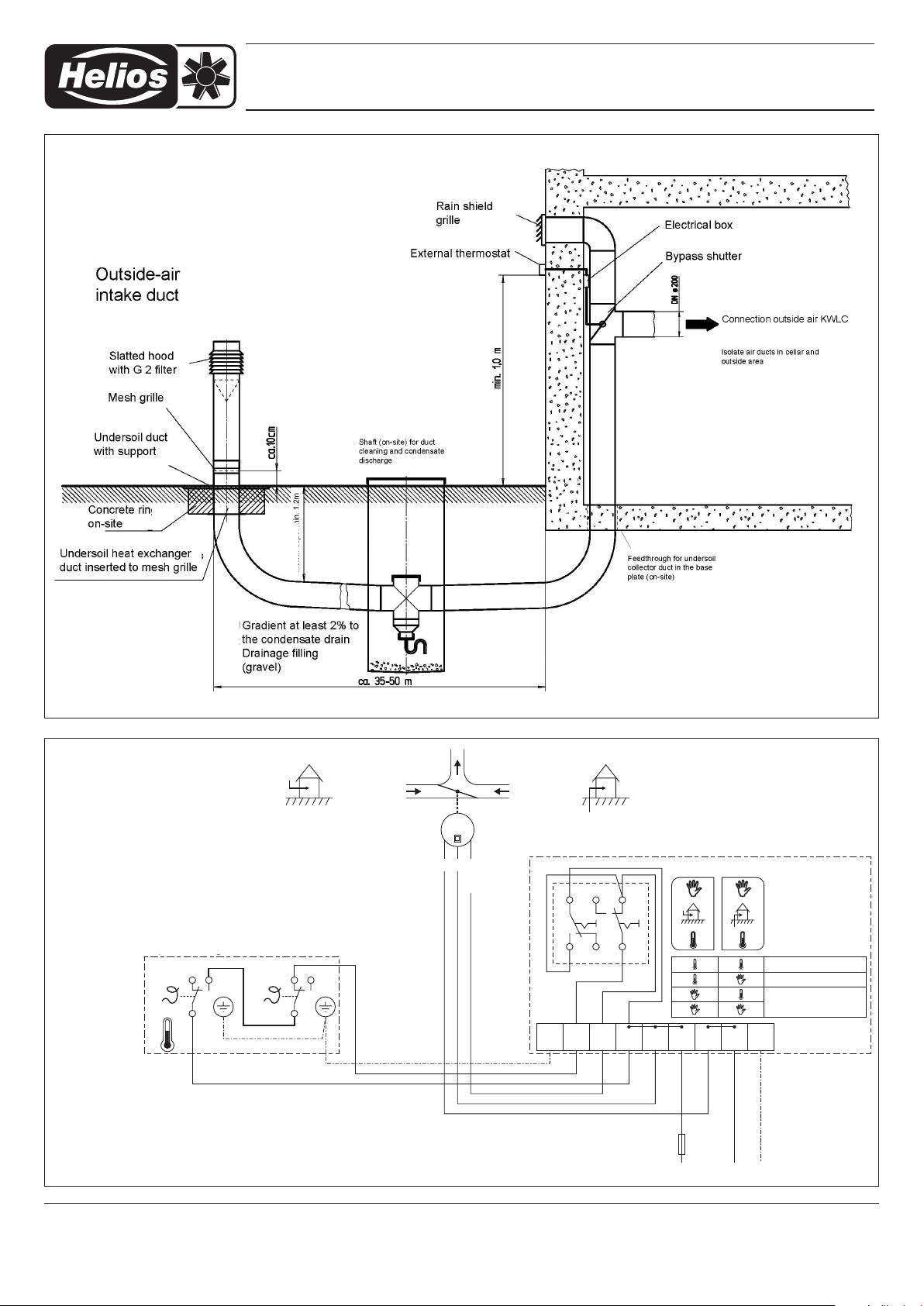
Außenluft
Erdwärme
M
NL
L-auf
25
31 64
Wippen
L1 NL1L1
L1 NPE
PEN
PE 12
Stellmotor auf “1”
Ruhezustand =
Erdwärme
Von 5°C bis 20°C
wird “Außenluft-
direkt” geschaltet
Außenluft direkt
Außenluft über Erdwärme
2 - fach Thermostat
Schalter Manuell / Thermostat
Stellmotor für
Klappenantrieb
12 3
Thermostat Betrieb
manuell Außenluft
manuell Erdwärme
5°C 20°C
Bypassklappe
L
L
Temperatureinstellung vornehmen !
Fig. 2
Basic diagram for installation of LEWT in buildings without basements
below the foundation - drainage shaft at lowest point.
Ground-to-Air Heat Exchanger LEWT Kit
SS-798.1
“Outside air direct” is
activated from 5°C to
20°C
2 stage thermostat
Set temperature!
Depth
Bypass shutter
Outside air Geothermal heat
Servomotor for shutter actuator
Servomotor at “1”
Idle state=
Geothermal heat
Outside air direct
Outside air via geothermal heat
Switch manual/thermostat
Rockers
Thermostat operation
Manual geotherm. heat
Manual outside air
Service and Information
D HELIOS Ventilatoren GmbH + Co KG · Lupfenstraße 8 · 78056 VS-Schwenningen F HELIOS Ventilateurs · Le Carré des Aviateurs · 157 av. Charles Floquet · 93155 Le Blanc Mesnil Cedex
CH HELIOS Ventilatoren AG · Tannstrasse 4 · 8112 Otelfingen GB HELIOS Ventilation Systems Ltd. · 5 Crown Gate · Wyncolls Road · Severalls Industrial Park ·
A HELIOS Ventilatoren · Postfach 854 · Siemensstraße 15 · 6023 Innsbruck Colchester · Essex · CO4 9HZ
4
Print no. 91 616 -001/ 0819
 Loading...