


Helios Ventilatoren
MONTAGE UND BETRIEBSVORSCHRIFT NR. 82 462
Erweiterungsmodul
KWL 45 EM
für Wand-Einbaugerät
KWL EC 45 (Hybridlüftung)
D

Montage- u. Betriebsvorschrift
D
KAPITEL 1
SICHERHEIT
1.0 Wichtige Informationen
Erweiterungsmodul KWL EM 45
Zur Sicherstellung einer einwandfreien Funktion und zur eigenen Sicherheit sind alle
achstehenden Vorschriften genau durchzulesen und zu beachten.
n
Dieses Dokument ist Teil des Produktes und als solches zugänglich und dauerhaft aufzubewahren um einen sicheren Betrieb des Erweiterungsmoduls zu gewährleisten. Alle
anlagenbezogenen Sicherheitsvorschriften müssen eingehalten werden.
für EcoVent Verso
GEFAHR
WARNUNG
VORSICHT
GEFAHR
1.1 Warnhinweise
Nebenstehende Symbole sind sicherheitstechnische Warnhinweise. Zur Vermeidung von Verletzungsrisiken und Gefahrensituationen, müssen alle Sicherheitsvorschriften bzw.
Symbole in diesem Dokument unbedingt beachtet werden!
1.2 Sicherheitshinweise
Für Einsatz, Anschluss und Betrieb gelten besondere Bestimmungen; bei Zweifel ist Rückfrage erforderlich. Weitere Informationen
sind den einschlägigen Normen und Gesetzestexten zu entnehmen.
Bei allen Arbeiten am Gerät sind die allgemein gülti-
gen Arbeitsschutz- und Unfallverhütungsvorschriften einzu-
halten!
• Alle elektrischen Arbeiten, sowie die Inbetriebnahme, War-
tungs- und Installationsarbeiten dürfen nur von autorisiertem
Elektrofachpersonal durchgeführt werden!
• Vor allen Reinigungs-, Wartungs- und Installationsarbeiten
oder vor Öffnen des Anschlussraums sind folgende Punkte
einzuhalten:
– Gerät allpolig vom Netz trennen und gegen Wiederein schalten sichern!
• Alle anlagenbezogenen Sicherheitsvorschriften sind einzu-
halten! Gegebenenfalls müssen weitere länderspezifische
Vorschriften eingehalten werden!
KAPITEL 2
ALLGEMEINE HINWEISE
GEFAHR
1.3 Personalqualifikation
GEFAHR!
Die Elektroanschlüsse und Inbetriebnahme sowie Installations-, Instandhaltungs-
und Wartungsarbeiten des Erweiterungsmodules dürfen nur von Elektrofachkräften
ausgeführt werden.
2.0 Garantieansprüche – Haftungsausschluss
Alle Ausführungen dieser Dokumentation müssen beachtet werden, sonst entfällt die
Gewährleistung. Gleiches gilt für Haftungsansprüche an Helios. Der Gebrauch von Zubehörteilen, die nicht von Helios empfohlen oder angeboten werden, ist nicht statthaft.
Eventuell auftretende Schäden unterliegen nicht der Gewährleistung. Veränderungen
und Umbauten am Gerät sind nicht zulässig und führen zum Verlust der Konformität,
jegliche Gewährleistung und Haftung ist in diesem Fall ausgeschlossen.
1

Montage- u. Betriebsvorschrift
2.1 Vorschriften – Richtlinien
2.2 Sendungsannahme
Die Lieferung enthält das Erweiterungsmodul: KWL 45 EM (Best.-Nr. 3012)
2.3 Einlagerung
Bei Einlagerung über einen längeren Zeitraum sind zur Verhinderung schädlicher Ein-
wirkungen folgende Maßnahmen zu treffen:
Schutz durch trockene, luft- und staubdichte Verpackung (Kunststoffbeutel mit
Trockenmittel und Feuchtigkeitsindikatoren). Der Lagerort muss erschütterungsfrei,
wassergeschützt und frei von übermäßigen Temperaturschwankungen sein. Schäden,
deren Ursprung in unsachgemäßem Transport, unsachgemäßer Einlagerung oder Inbe triebnahme liegen, sind nachweisbar und unterliegen nicht der Gewährleistung.
2.4 Einsatzbereich
Das Erweiterungsmodul KWL 45 EM kann zur Ansteuerung von KWL-Wand-Einbau-
geräten EcoVent Verso angeschlossen werden.
Des Weiteren können mit dem Erweiterungsmodul weitere im Helios-Programm verfüg-
VORSICHT
baren Ventilatoren z.B. stromüberwacht werden.
Ein bestimmungsfremder Einsatz ist nicht zulässig!
Erweiterungsmodul KWL EM 45
Bei ordnungsgemäßer Installation und bestimmungsgemäßem Betrieb entspricht das
erät den zum Zeit punkt seiner Herstellung gültigen Vorschriften und EU-Richtlinien.
G
ie Sendung ist sofort bei Anlieferung auf Beschädi gungen und Typenrichtigkeit zu prü-
D
fen. Falls Schäden vorliegen, umgehend Schadensmeldung unter Hinzuziehung des
Transportunternehmens veranlassen. Bei nicht fristgerechter Reklamation gehen evtl.
Ansprüche verloren.
für EcoVent Verso
D
KAPITEL 3
TECHNISCHE
DATEN
HINWEIS
3.0 Technische Daten
KWL 45 EM
Best.-Nr. 3012
Versorgung 230 V~ 50/60 Hz
Frequenz muss mit dem zu überwachenden Ventilator identisch sein.
Maximaler Verbraucherstrom des Ventilators 2,0 A
Relaiskontakt:
250 VAC 3A AC1 (ohmsche Last)
250 VAC 1A AC15 (AC-Relais, Schütz)
24VDC 2A DC13 (DC-Relais, Schütz)
Minimale Belastung 1V/1 mA (Gold Kontakte)
Das Relais ist mit einem Goldkontakt ausgestattet. Dies ermöglicht das Schalten sehr
kleiner DC Ströme. Werden einmal AC-Ströme geschaltet, ist der Kontakt nur noch für
diese Anwendung einsetzbar.
Schaltschwelle über Poti einstellbar, ca. 10 mA bis ca. 400 mA +-5mA,
Einstellwert stark abhängig von dem zu überwachenden Ventilator und dessen
induktiver / kapazitiver Last
Einbau Standard UP-Dose
Temperatur -5 bis +40°C
Schutzart IP20
Schutzklasse 2
Abmessungen B40 x H40 x T29
Schaltschema SS-1118
Konform nach DIN EN 60335-1
Entsprechend den neuesten Vorschriften gemäß EMV-Richtlinie ausgeführt und geprüft.
2

Montage- u. Betriebsvorschrift
D
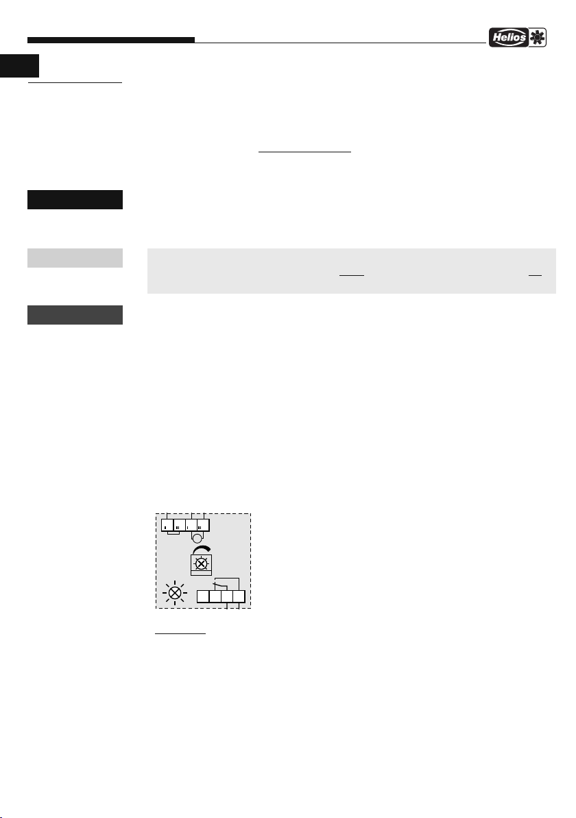
3.1 Prinzip-/Installationsbeispiel SS-1118
Erweiterungsmodul KWL EM 45
für EcoVent Verso
3

Montage- u. Betriebsvorschrift
1
2
4
6
5
7
K
WL 45 BE
U
8 9
10
11
UP-Dose
1
1
1
2
2
2
3
3
3
L
L
L
N
N
N
1
0
0
m
³
/
h
1
0
0
m
³
/
h
1
0
0
m
³
/
h
6
0
m
³
/
h
6
0
m
³
/
h
6
0
m
³
/
h
3
5
m
³
/
h
3
5
m
³
/
h
3
5
m
³
/
h
z.B. ELS V
...
z.
B
.
ELS
V
.
.
.
z
.
B
.
E
L
S
V
.
.
.
+
+
+
Installations Beispiel mit einem KWL EC 45 und bis zu 3 KWL 45 EM
3
3
3
2
2
2
1
1
1
L
L
L
L
L
L
N
N
N
N
N
N
88888
88888
88888
A
A
A
230
V
~ /
12 V
=
KWL 45 SNU
KW
L
E
C 4
5
:
D
e
t
a
illie
rt
er A
n
schlu
s
s
sieh
e S
S-1
091
M1
/
M
2
KWL EC 45
KWL 45 EM
KW
L 45 E
M
KW
L
45 E
M
230 V
~
N
N
N
L
L
L
Beleuchtung
Bel
eucht
ung
B
e
l
e
u
c
h
t
u
n
g
Schal
t
er
S
c
h
a
l
t
e
r
S
c
h
a
l
t
e
r
J-Y
(S
T)
Y
0,
8
m
m
m
a
x.
30
m
J-Y
(S
T)
Y
0,
8
m
m
m
a
x.
30
m
J-Y (ST) Y 0,8 mm
max. 30 m
2
2
2
230
V~
230
V
~
230
V
~
3.2 Installationsbeispiel mit einem KWL EC 45 und bis zu 3 KWL 45 EM SS-1158
Erweiterungsmodul KWL EM 45
für EcoVent Verso
D
4

Montage- u. Betriebsvorschrift
3
2
1
LLNN
88888
A
D
KAPITEL 4
UNKTION
F
GEFAHR
HINWEIS
ACHTUNG
4.0 Funktionsbeschreibung
Das KWL 45 EM Erweiterungsmodul überwacht den Betriebsstrom eines Ventilators. Ein
Relaiskontakt signalisiert mit einem Schließer den Betriebszustand „ Ventilator läuft”. Der
Relais-Kontakt kann in eine externe Steuerung zur Auswertung integriert werden.
4.1 Informationen für die Elektrofachkraft
– Versorgung
Das KWL 45 EM ist für den Betrieb in einer UP-Dose vorgesehen.
Der Zugang während des Betriebs ist nur einer Elektrofachkraft gestattet.
Über die Klemme L‘ und N‘ wird das KWL 45 EM mit Netzspannung versorgt. Die Klemme
L‘‘ kann als Klemmstation für die Ventilatorversorgung verwendet werden, für das Modul
selbst hat sie keine Bedeutung.
Der zu überwachende Strom des Ventilators findet über die Klemmen N‘ und N‘‘ statt.
Somit muss die N-Versorgung des Ventilators über die Klemme N‘‘ durchgeführt werden.
Für jeden zu überwachenden Ventilator wird je ein KWL 45 EM Modul benötigt.
Das Erweiterungsmodul KWL 45 EM darf nur im Bereich der genannten Daten be-
trieben werden. Entsprechend ist ein Sicherheitspuffer (Ventilator Toleranz) von ca.
10 % zum max. Strom, einzuhalten. Eine dauernde Überlastung des Moduls führt
zu dessen Zerstörung!
– Relais
Der Relaiskontakt kann zur Signalisierung des Schaltzustandes in externen Steuerungen
eingesetzt werden. Kontaktbelastung beachten siehe Technische Daten.
Kontakt Klemme 2/3 geschlossen bedeutet Schaltschwelle überschritten, „ Ventilator läuft”.
Sinkt der überwachte Strom unter die Schaltschwelle, öffnet der Kontakt Klemme 2/3
wieder, „ Ventilator aus”.
Das Relais ist mit einem Goldkontakt ausgestattet. Dies ermöglicht das Schalten sehr
kleiner DC Ströme. Werden einmal AC-Ströme geschaltet, ist der Kontakt nur noch für
diese Anwendung einsetzbar.
Erweiterungsmodul KWL EM 45
für EcoVent Verso
4.2 Potentiometer / Schaltschwelle einstellen
In der Potentiometerstellung „ min” (Auslieferungszustand) werden
die allermeisten Helios Ventilator Typen erkannt. Wird die
Strom-Schaltschwelle durch einen laufenden Ventilator über
schritten, schaltet das Relais. Dies wird gleichzeitig durch
die grüne LED signalisiert. Ein justieren mit dem Potentiometer
ist nicht notwendig.
Situation 1:
Das Relais hat geschaltet, die LED leuchtet, obwohl der Ventilator nicht läuft. Dies liegt
In wenigen Fällen ist es erforderlich die Schaltschwelle
nachzujustieren.
an dem Ruhe/Standbystrom des Ventilators (interne Elektronik-Steuerung des Ventilators).
Dieser liegt jetzt über der Schaltschwelle.
Nachjustieren:
Bei stehendem Ventilator, das Potentiometer langsam in Richtung „max” drehen, bis die
grüne LED erlischt. Zur Sicherheit minimal weiter drehen. Die Schaltschwelle, die über
dem Ruhe/Standbystrom des eingesetzten Ventilators liegt, ist nun gefunden.
5

Montage- u. Betriebsvorschrift
Potentiometer
B
e
t
r
i
e
b
s
s
t
r
o
m
S
t
a
n
d
b
y
s
t
r
o
m
Situation 2:
Im umgekehrten Fall läuft der Ventilator. Das Relais hat nicht geschaltet, die LED ist aus.
Nachjustieren:
Das Potentiometer in Richtung „min” drehen, bis die LED leuchtet.
Die Schaltschwelle liegt jetzt wieder unterhalb des Ventilator Betriebsstroms.
Erweiterungsmodul KWL EM 45
für EcoVent Verso
D
HINWEIS
Hinweis:
Im Idealfall ist die Schaltschwelle zwischen dem Ventilator Standbystrom und dem
Ventilator-Betriebsstrom eingestellt.
6

Alle Abbildungen ohne Gewähr!
Als Referenz am Gerät griffbereit aufbewahren! Druckschrift-Nr.
Service und Information
D HELIOS Ventilatoren GmbH + Co KG · Lupfenstraße 8 · 78056 VS-Schwenningen F HELIOS Ventilateurs · Le Carré des Aviateurs · 157 avenue Charles Floquet · 93155 Le Blanc Mesnil Cedex
CH HELIOS Ventilatoren AG · Tannstrasse 4 · 8112 Otelfingen GB HELIOS Ventilation Systems Ltd. · 5 Crown Gate · Wyncolls Road · Severalls Industrial Park ·
A HELIOS Ventilatoren · Postfach 854 · Siemensstraße 15 · 6023 Innsbruck Colchester · Essex · CO4 9HZ
82 462/10.16
www.heliosventilatoren.de

Helios Ventilatoren
INSTALLATION AND OPERATING INSTRUCTIONS NO. 82 462
Extension Module
KWL 45 EM
for wall installation unit
KWL EC 45 (hybrid ventilation)
UK

Installation and Operating Instructions
UK
.0 Important information
CHAPTER 1
SAFETY
ANGER
D
WARNING
CAUTION
1
In order to ensure complete and effective operation and for your own safety, all of the
ollowing instructions should be read carefully and observed.
f
This document should be regarded as part of the product and as such should be kept
accessible and durable to ensure the safe operation of the extension module. All plant-
elated safety regulations must be observed.
r
1.1 Warning instructions
The adjacent symbols are safety-relevant warning symbols.
All safety regulations and/or symbols in this document must
be absolutely adhered to, so that any risks of injury and dangerous situations are avoided!
Extension Module KWL EM 45
for EcoVent Verso
DANGER
DANGER
1.2 Safety instructions
Special regulations apply for use, connection and operation; consultation is required in case of doubt. Further information can be found
in the relevant standards and legal texts.
With regard to all work on the fan, the generally applicable
safety at work and accident prevention regulations must be
observed!
• All electrical work, as well as the commissioning, mainten-
ance and installation work must only be carried out by aut horised qualified electricians!
• The following must be observed before all cleaning, main-
tenance and installation work or before opening the terminal
compartment:
– Isolate the device from the mains power supply and secure
against being switched on again!
• All plant-related safety regulations must be observed! If
applicable, further country-specific regulations must also be
observed!
1.3 Personnel qualification
DANGER!
The electrical connections and commissioning as well as installation, servicing
and maintenance work on the extension module must only be carried out by qualified
electricians.
CHAPTER 2
GENERAL INFORMATION
2.0 Warranty claims – Exclusion of liability
All versions of this documentation must be observed, otherwise the warranty shall cease to apply. The same applies to liability claims against Helios. The use of accessory
parts, which are not recommended or offered by Helios, is not permitted. Any possible
damages are not covered by the warranty. Changes and modifications to the unit are
not permitted and lead to a loss of conformity, and any warranty and liability shall be
excluded in this case.
1

Installation and Operating Instructions
.1 Certificates - Guidelines
2
If the unit is installed correctly and used for its intended purpose, it conforms to all ap-
licable provisions and EU guidelines at its date of manufacture.
p
2.2 Receipt
The delivery contains the extension module: KWL 45 EM (Ref.no. 3012)
The shipment must be checked for damage and correctness immediately upon delivery. If there is any damage, promptly report the damage with the assistance of the
transport company. If complaints are not made within the agreed period, any claims
could be lost.
2.3 Storage
When storing for a prolonged time, the following steps are to be taken to avoid dama-
ging influences:
Protection by dry, airtight and dust-proof packaging (plastic bag with desiccant and hu midity indicators). The storage site must be vibration-free, water-tight and free from ex cessive temperature fluctuations. Damage caused during improper transportation, sto rage or commissioning is traceable and is not covered by warranty.
2.4 Area of application
The extension module KWL 45 EM can be connected to control KWL wall installation
units EcoVent.
Furthermore, for example, other fans in the Helios range can be current-monitored with
CAUTION
the extension module.
Any use other than the intended use is not permitted!
Extension Module KWL EM 45
for EcoVent Verso
UK
CHAPTER 3
TECHNICAL
DATA
NOTE
3.0 Technical data
KWL 45 EM
Ref.no. 3012
Supply 230 V~ 50/60 Hz
Frequency must be identical with the fan to be monitored.
Maximum load current of fan 2.0 A
Relay contact:
250 VAC 3A AC1 (ohmic load)
250 VAC 1A AC15 (AC relay, contactor)
24VDC 2A DC13 (DC relay, contactor)
Minimum load 1V/1 mA (gold contacts)
The relay is fitted with a gold contact. This enables the switching of very low
DC currents. Once AC currents are switched, the contact can then only be used for
this application.
Switching threshold adjustable via Poti, approx. 10 mA to approx. 400 mA +-5mA,
Setpoint strongly dependent on the fan to be monitored and its inductive / capacitive
load
Installation Standard flush-mounted box
Temperature -5 to +40 °C
Protection cat. IP20
Protection class 2
Dimensions W40 x H40 x D29
Circuit diagram SS-1118
Compliant with DIN EN 60335-1
Designed and tested according to the latest regulations pursuant to the EMC Directive.
2

Installation and Operating Instructions
UK
.1 Principle/installation example SS-1118
3
Extension Module KWL EM 45
E.g. ELS V...Light
for EcoVent Verso
Switch
see SS-1091
KWL EC 45:
Detailed connection
Flush-
mounted
Installation example with one KWL EC 45
Ref.no. 3012
Duration-L for electronic types*
e.g. NC, P, F
with automatic start such as
*Duration-L for electronic types
box
E.g. ELS V...
Principle example
Switch
3

Installation and Operating Instructions
1
2
4
6
5
7
K
WL 45 BE
U
8 9
10
11
UP-Dose
1
1
1
2
2
2
3
3
3
L
L
L
N
N
N
1
0
0
m
³
/
h
1
0
0
m
³
/
h
1
0
0
m
³
/
h
6
0
m
³
/
h
6
0
m
³
/
h
6
0
m
³
/
h
3
5
m
³
/
h
3
5
m
³
/
h
3
5
m
³
/
h
z.B. ELS V
...
z.
B
.
ELS
V
.
.
.
z
.
B
.
E
L
S
V
.
.
.
+
+
+
Installations Beispiel mit einem KWL EC 45 und bis zu 3 KWL 45 EM
3
3
3
2
2
2
1
1
1
L
L
L
L
L
L
N
N
N
N
N
N
88888
88888
88888
A
A
A
230
V
~ /
12 V
=
KWL 45 SNU
KW
L
E
C 4
5
:
D
e
t
a
illie
rt
er A
n
schlu
s
s
sieh
e S
S-1
091
M1
/
M
2
KWL EC 45
KWL 45 EM
KW
L 45 E
M
KW
L
45 E
M
230 V
~
N
N
N
L
L
L
Beleuchtung
Bel
eucht
ung
B
e
l
e
u
c
h
t
u
n
g
Schal
t
er
S
c
h
a
l
t
e
r
S
c
h
a
l
t
e
r
J-Y
(S
T)
Y
0,
8
m
m
m
a
x.
30
m
J-Y
(S
T)
Y
0,
8
m
m
m
a
x.
30
m
J-Y (ST) Y 0,8 mm
max. 30 m
2
2
2
230
V~
230
V
~
230
V
~
.2 Installation example with a KWL EC 45 and up to 3 KWL 45 EM SS-1158
3
Extension Module KWL EM 45
for EcoVent Verso
UK
Switch
E.g. ELS V...
Light
E.g. ELS V...
Light
Switch
E.g. ELS V...
Light
Switch
Installation example with one KWL EC 45 and up to 3 KWL 45 EM
see SS-1091
KWL EC 45:
Detailed connection
4
Flush-
mounted
box
Installation and Operating Instructions
3
2
1
LLNN
88888
A
UK
.0 Functional description
CHAPTER 4
UNCTION
F
DANGER
OTE
N
ATTENTION
4
The KWL 45 EM extension module monitors the operating current of a fan. A relay con-
tact indicates the operating status “Fan on” with a normally open contact. The relay
contact can be integrated in an external control system for evaluation.
.1 Informationen for the qualified electrician
4
– Supply
The KWL 45 EM is intended for use in a flush-mounted box.
Only qualified electricians are allowed access to the unit during operation.
The KWL 45 EM is supplied with mains voltage via terminals L‘ and N‘. Terminal
L‘‘ can be used as a terminal station for the fan power supply, it has no significance for
the module itself.
The fan current to be monitored findet occurs via terminals N‘ and N‘‘.
Thus, the N-supply of the fan must be conducted via terminal N‘‘.
A KWL 45 EM module is required for each fan to be monitored.
The extension module KWL 45 EM must only be opreated within the range of the
specified data. Accordingly, a safety buffer (fan tolerance) of approx.
10 % to max. current must be observed. The permanent overloading of the module
will result in its destruction!
– Relay
The relay contact can be used to indicate the switching state in external control systems.
Note contact load - see Technical data.
Contact terminal 2/3 closed means switching threshold exceeded, “Fan on”.
If the monitored current falls below the switching threshold, the contact terminal 2/3
will open again, “Fan off”.
The relay is fitted with a gold contact. This enables the switching of very low
DC currents. Once AC currents are switched, the contact can then only be used for
this application.
Extension Module KWL EM 45
for EcoVent Verso
4.2 Adjust potentiometer / switching threshold
The majority of Helios fan types are detected in the potentiometer
position “min” (as delivered). If the current-switching threshold
is exceeded by a running fan, the relay will switch. This is simultaneously indicated by the green LED. Adjustment with the potentiometer is not necessary.
In a minority of cases, it is necessary to adjust the switching
Situation 1:
The relay has switched, the LED is lit up, but the fan is not on. This is because of the
threshold.
quiescent/standby current of the fan (internal electronic control of the fan).
This is now above the switching threshold.
Readjust:
When the fan has stopped, slowly turn the potentiometer in the “max” direction, until the
green LED goes out. Continue to turn fractionally for good measure. The switching thres hold, which is above the quiescent/standby current of the fan, is now found.
5

Installation and Operating Instructions
Potentiometer
B
e
t
r
i
e
b
s
s
t
r
o
m
S
t
a
n
d
b
y
s
t
r
o
m
Situation 2:
In the opposite case, the fan is on. The relay has not switched, the LED is off.
Readjust:
Turn the potentiometer in “min” direction until the LED lights up.
The switching threshold is now below the fan operating current again.
Extension Module KWL EM 45
for EcoVent Verso
UK
NOTE
Note:
Ideally, the switching threshold is set between the fan standby current and the fan
operating current.
nt
urre
ndby c
Sta
Ope
ra
ti
ng
c
urre
nt
6

All illustrations subject to correction!
Keep at hand for future reference! Print no.
Service and Information
D HELIOS Ventilatoren GmbH + Co KG · Lupfenstraße 8 · 78056 VS-Schwenningen F HELIOS Ventilateurs · Le Carré des Aviateurs · 157 avenue Charles Floquet · 93155 Le Blanc Mesnil Cedex
CH HELIOS Ventilatoren AG · Tannstrasse 4 · 8112 Otelfingen GB HELIOS Ventilation Systems Ltd. · 5 Crown Gate · Wyncolls Road · Severalls Industrial Park ·
A HELIOS Ventilatoren · Postfach 854 · Siemensstraße 15 · 6023 Innsbruck Colchester · Essex · CO4 9HZ
82 462/10.16
www.heliosventilatoren.de
 Loading...