


Helios Ventilatoren
MONTAGE- UND BETRIEBSVORSCHRIFT
DE
INSTALLATION AND OPERATING INSTRUCTIONS
Brandgas-Dachventilatoren
Smoke exhaust roof fans
EN
B VD
in Temperaturklassen F400/F600
in temperature classes F400, F600

Montage- und Betriebsvorschrift
Inhaltsverzeichnis
KAPITEL 1 GRUNDLEGENDE SICHERHEITSHINWEISE ........................................... Seite 1
1.0 Wichtige Informationen .................................................................. Seite 1
1.1 Warnhinweise ......................................................................... Seite 1
1.2 Sicherheitshinweise ..................................................................... Seite 1
1.3 Einsatzbereich ......................................................................... Seite 2
1.4 Grenzen ............................................................................. Seite 3
1.5 Berührungsschutz ...................................................................... Seite 3
1.6 Personalqualifikation .................................................................... Seite 3
1.7 Förder- und Drehrichtung ................................................................ Seite 3
1.8 Drehzahlregelung ...................................................................... Seite 3
1.9 Funktionssicherheit – Notbetrieb ........................................................... Seite 4
KAPITEL 2 ALLGEMEINE HINWEISE ......................................................... Seite 4
2.0 Garantieansprüche – Haftungsausschluss .................................................... Seite 4
2.1 Vorschriften – Richtlinien ................................................................. Seite 4
2.2 Transport ............................................................................ Seite 4
2.3 Sendungsannahme ..................................................................... Seite 5
2.4 Einlagerung ........................................................................... Seite 5
2.5 Brandgas Serienausführung .............................................................. Seite 5
2.6 Leistungsdaten ........................................................................ Seite 5
2.7 Geräuschangaben ...................................................................... Seite 6
KAPITEL 3 MONTAGE ..................................................................... Seite 6
3.0 Konstruktiver Aufbau .................................................................... Seite 6
3.1 Montage – Einbau ...................................................................... Seite 7
3.2 Dachmontage ......................................................................... Seite 7
3.3 Aufstellung ........................................................................... Seite 9
3.4 Lager-Zustandsdiagnostik ............................................................... Seite 10
3.5 Mindestluftspalte bei Einhaltung der Werkstoffpaarung ......................................... Seite 10
3.6 Maximal zulässige Schwingungsgrenzwerte gemäß ISO 14694 / ISO 10816-3 ...................... Seite 11
3.7 Empfohlene Anzugsdrehmomente für Befestigungsschrauben ................................... Seite 11
3.8 Elektrischer Anschluss ................................................................. Seite 12
3.9 Inbetriebnahme ....................................................................... Seite 12
3.10 Betrieb ............................................................................. Seite 12
B VD – Brandgas-Dachventilatoren F400/F600
KAPITEL 4 INSTANDHALTUNG UND WARTUNG ............................................... Seite 13
4.0 Instandhaltung und Wartung ............................................................. Seite 13
4.1 Reinigung ........................................................................... Seite 13
4.2 Reparatur ........................................................................... Seite 13
4.3 Hinweise – Störungsursache ............................................................. Seite 14
4.4 Ersatzteile ........................................................................... Seite 15
4.5 Stilllegen und Entsorgen ................................................................ Seite 15
KAPITEL 5 TECHNISCHE DATEN ........................................................... Seite 15
5.0 Technische Daten ..................................................................... Seite 15
5.1 Typenschlüssel ....................................................................... Seite 16
5.2 Typenschild .......................................................................... Seite 16
5.3 Motorenschild ........................................................................ Seite 16
KAPITEL 6 SCHALTPLAN-ÜBERSICHT ....................................................... Seite 17
6.0 Schaltpläne .......................................................................... Seite 17
KAPITEL 7. .............................................................................. Seite 20
7.0 Inbetriebnahmeprotokoll ................................................................ Seite 20
7.1 Prüf- und Wartungsplan ................................................................ Seite 22
7.2 Leistungserklärung .................................................................... Seite 24
Erreichen der Lebensdauer, Entsorgung
Bauteile und Komponenten des Ventilators, die ihre Lebensdauer erreicht haben, z.B. durch Verschleiß, Korrosion, mechanische Belastung, Ermüdung und / oder
durch andere, nicht unmittelbar erkennbare Einwirkungen, sind nach erfolgter Demontage entsprechend den nationalen und internationalen Gesetzen und Vorschriften
fach- und sachgerecht zu entsorgen. Das Gleiche gilt auch für im Einsatz befindliche Hilfsstoffe wie Öle und Fette oder sonstige Stoffe.
Die bewusste oder unbewusste Weiterverwendung verbrauchter Bauteile wie z.B. Laufräder, Wälzlager, Keilriemen, etc. kann zu einer Gefährdung von Personen, der
Umwelt sowie von Maschinen und Anlagen führen. Die entsprechenden, vor Ort geltenden Betreibervorschriften sind zu beachten und anzuwenden.

Montage- und Betriebsvorschrift
KAPITEL 1
GRUNDLEGENDE
SICHERHEITSHINWEISE
1.0 Wichtige Informationen
1.1 Warnhinweise
B VD – Brandgas-Dachventilatoren F400/F600
DE DE
Zur Sicherstellung einer einwandfreien Funktion und zur eigenen Sicherheit sind alle nachstehenden Vorschriften genau
durchzulesen und zu beachten.
Dieses Dokument ist Teil des Produktes und als solches zugänglich und dauerhaft aufzubewahren. Der Betreiber ist
für die Einhaltung aller anlagenbezogenen Sicherheitsvorschriften verantwortlich.
Die dem Gerät zugehörige Leistungserklärung und das Gerätetypenschild ist zu beachten!
Nebenstehende Symbole sind sicherheitstechnische Warnhinweise. Zur Vermeidung jeglicher Gefahren-
situation, müssen alle Sicherheitsvorschriften bzw. Symbole unbedingt beachtet werden!
m
WARNUNG
m
VORSICHT
m
ACHTUNG
GEFAHR
GEFAHR
m
Warnung vor Gefahren, die bei Missachtung der Maßnahmen unmittelbar zu Tod oder schweren Verletzungen
führen.
WARNUNG
m
Warnung vor Gefahren, die bei Missachtung der Maßnahmen zu Tod oder schweren Verletzungen führen können.
VORSICHT
m
Warnung vor Gefahren, die bei Missachtung der Maßnahmen zu Verletzungen führen können.
ACHTUNG
Warnung vor Gefahren, die bei Missachtung der Maßnahmen zu Sachschäden führen können.
1.2 Sicherheitshinweise
Schutzbrille
l
Dient zum Schutz vor Augenverletzungen.
Gehörschutz
p
Dient zum Schutz vor allen Arten von Lärm.
Arbeitschutzkleidung
r
Dient vorwiegend zum Schutz vor Erfassen durch bewegliche Teile.
Keine Ringe, Ketten oder sonstigen Schmuck tragen.
Schutzhandschuhe
n
Schutzhandschuhe dienen zum Schutz der Hände vor Reibung, Abschürfungen, Einstichen
oder tieferen Verletzungen sowie vor Berührung mit heißen Oberflächen.
Sicherheitsschuhe
m
Sicherheitsschuhe dienen zum Schutz vor schweren herabfallenden Teilen und verhindern
Ausrutschen auf rutschigem Untergrund.
Haarnetz
Das Haarnetz dient vorwiegend zum Schutz vor Erfassen von langen Haaren durch beweg liche Teile.
Für Einsatz, Anschluss und Betrieb bei Brandgas-Dachventilatoren gelten besondere
Bestimmungen; bei Zweifel ist Rückfrage erforderlich. Die Bundes- sowie regiona-
le Brandschutzverordung ist zu beachten! Weitere Informationen sind den einschlägigen Normen, Bundesgesetzen, Landesbauverordnungen, Richtlinien sowie
Sonderbauverordnungen zu entnehmen.
m Bei allen Arbeiten am Ventilator sind die allgemein gültigen Arbeitsschutz-
und Unfallverhütungsvorschriften einzuhalten!
•
Es muss sichergestellt werden, dass der Brandgas-Dachventilator im
Entrauchungsfall bis zum elektromechanischen Ausfall betrieben wird. Vorhandene
Motorschutzeinrichtungen sind zu überbrücken!
•
Vor allen Wartungs- und Installationsarbeiten oder vor Öffnen des Anschlussraums ist
das Gerät allpolig vom Netz zu trennen und gegen unerwünschtes Wiedereinschalten
zu sichern! Der elektrische Anschluss darf nur von einer autorisierten Elektrofachkraft
entsprechend den nachstehenden Anschlussplänen ausgeführt werden!
•
Ventilator bis zum Einbau nur verpackt bewegen!
•
Brandgas-Dachventilator nur mit für das Gewicht geeigneten Transportmitteln bewegen, beim Transport Sicherheitsschuhe tragen!
•
Beiliegende Transportskizze beachten!
•
Beim Auspacken des Geräts Handschuhe/Sicherheitsschuhe tragen. Geeignete
Tragkrafteigenschaften des Befestigungsuntergrunds sicherstellen und diesbezüg-
1

Montage- und Betriebsvorschrift
•
•
•
•
•
•
•
•
•
•
•
•
•
•
•
B VD – Brandgas-Dachventilatoren F400/F600
lich geeignete Befestigungsmittel verwenden.
Der Einbaubereich muss so gestaltet werden, dass keine Personen durch die heißen
Gase gefährdet werden können.
Der Ausblasbereich des Ventilators muss frei von entzündbaren Materialien sein und
darf für Personen nicht zugänglich sein.
Der Ansaugbereich der Motorkühlluft muss frei sein und darf nicht versperrt werden.
Es ist zu prüfen ob die Einbausituation das Tragen von Gehörschutz erfordert.
Der Betreiber ist für die Einhaltung aller anlagenbezogenen Sicherheitsvorschriften
verantwortlich!
Eine gesicherte Stromversorgung und ein elektrischer Anschluss in Funktionserhalt
ist gemäß der gültigen Vorschriften und Richtlinien vorzusehen.
Es muss sichergestellt werden, dass kein Schnee in den Brandgas-Dachventilator
eindringt. Die lokale Schneelast und der Einsatz des Deflektors (Zubehör) ist zu
prüfen.
Es muss sichergestellt werden, dass Niederschlagswasser aus dem Ventilator an
den vorgesehenen Stellen ungehindert austreten kann.
Anormal häufiges Ein-/Ausschalten ist nicht zulässig.
Der Berührungsschutz für das Radiallaufrad gemäß DIN EN 13857 ist sicherzustellen.
Zur Einhaltung der Betriebssicherheit ist eine regelmäßige Schwingungskontrolle
durchzuführen! Alternativ empfiehlt es sich eine bauseitige Schwingungsüberwachung
zu installieren.
Angaben und zulässige Schwingungsgrenzwerte nach ISO 14694 aus der Tabelle
auf Seite 11, Kapitel 3.6 sind zu beachten.
Der Planer und Betreiber muss eine leichte Zugänglichkeit für Inspektions- und
Reinigungsarbeiten gewährleisten!
Eine gleichmäßige Zuströmung und ein freier Ausblas sind zu gewährleisten.
Der Brandgas-Dachventilator ist gegen das Abschalten durch Unbefugte zu sichern
(Revisionsschalter mit Vorhängeschloss in der Verriegelung für die Betriebsstellung).
1.3 Einsatzbereich
– Bestimmungsgemäßer Einsatz:
Die Brandgas-Dachventilatoren sind als Entrauchungsventilatoren mit Doppelfunktion (Entrauchung und Lüftung)
konzipiert. Sie sind zum Einsatz in maschinellen Rauchabzugsanlagen (MRA) zur Sicherstellung der Rauchableitung in
Sonderbauten, wie bspw. Verkaufsstätten, Großgaragen, Versammlungsstätten oder Industriebauten etc., bestimmt.
Die Geräte müssen innerhalb ihres Kennlinienfelds betrieben werden (s. Katalog). Vibrationen und eine Zunahme der
Geräuschentwicklung weisen auf einen Betrieb außerhalb des Kennlinienfeldes hin. Die Brandgas-Dachventilatoren
sind für den Einsatz innerhalb einer Anlage bestimmt. Sie haben keine eigene Steuerung und keine autonome NotStopp-Funktion.
Lüftungsbetrieb:
Der Brandgas-Dachventilator dient ausschließlich zur Förderung normaler, staubfreier und klimatisierter Luft sowie
sonstiger, nicht aggressiver und nicht explosiver Gase. Das Gerät ist auf eine Dauerfördermitteltemperatur von bis
zu 120°C ausgelegt. Der Ventilator kühlt sich selbst. Eine maximale Umgebungstemperatur von 60°C darf nicht
überschritten werden, auch im Entrauchungsbetrieb. Eine Mindestdrehzahl ist einzuhalten, siehe Drehzahlregelung in
Kapitel 1.8.
Entrauchungsbetrieb:
Darüber hinaus dient der Brandgas-Dachventilator als Entrauchungsventilator zur Förderung von Brandgasen gemäß
seiner Temperaturklasse und Zeitangabe:
Betrieb der Ventilatoren mit 4-poligem Antriebsmotor
Frequenz F400 F600
< 20 Hz Nicht zulässig
20 Hz - 49 Hz 90 min 90 min
50 Hz 120 min 120 min
Betrieb der Ventilatoren mit 6-poligem Antriebsmotor
Frequenz F400 F600
< 32 Hz Nicht zulässig
32 Hz - 49 Hz 90 min 90 min
50 Hz 120 min 120 min
m
WARNUNG
m Verletzungsgefahr während des Entrauchungsbetriebs durch heiße Oberflächen.
Sicherstellen, dass der Ventilator während des Betriebs unzugänglich ist, z. B. durch Umzäunung.
2

Montage- und Betriebsvorschrift
1.4 Grenzen
Räumlich:
Schnittstelle Energieversorgung:
Lüftungsbetrieb:
Die Motorlager sind nach 5 Jahren zu erneuern, auch bei Stillstand. Bei Verwendung einer Lager-Zustandsdiagnostik
gelten abweichende Bestimmungen, siehe Prüf- und Wartungsplan. Die Wicklungsisolation bzw. der Motor selbst muss
Entrauchungsbetrieb:
Nutzungsdauer bei Entrauchungsbetrieb einmalig 120 min. bzw. 90 min im Regelbetrieb (20 bzw. 32 Hz bis 49 Hz)
bei max. 400°C (F400) bis 600 °C (F600).
Das Gerät muss nach erfolgtem Entrauchungsbetrieb entsorgt werden!
B VD – Brandgas-Dachventilatoren F400/F600
DE DE
− Vernünftigerweise vorhersehbarer Fehlgebrauch:
Die Ventilatoren sind nicht zum Betrieb unter erschwerten Bedingungen wie z.B. hohe Feuchtigkeit, aggressive Medien,
längere Stillstandzeiten, starke Verschmutzung, übermäßige Beanspruchung durch klimatische, technische oder elektronische Einflüsse geeignet. Eine Verwendung in einer mobilen Einheit (z.B. Fahrzeuge, Flugzeuge, Schiffe, usw.) ist
nicht vorgesehen.
− Missbräuchlicher, untersagter Einsatz:
Aufstellung im direkten Kontakt mit Wasser. Förderung von explosionsfähigen Gasgemischen/Medien. Aufstellung
in einem/r explosionsgefährdeten Bereich/Atmosphäre. Betrieb ohne normgerechte Schutzeinrichtungen (z.B.
Schutzgitter). Förderung von Feststoffen oder Feststoffanteilen > 10 µm im Fördermedium sowie Flüssigkeiten.
Förderung von abrasiven und/oder die Ventilatorwerkstoffe angreifende Medien. Förderung von fetthaltigen
Fördermedien. Entrauchungsbetrieb mit aktiver Motorschutzeinrichtung.
Flucht- und Rettungswege dürfen nicht in unmittelbarer Nähe am Entrauchungsventilator vorbeiführen. Der Ventilator
muss so installiert werden, dass er für Wartungen, einschließlich Ein-/Ausbau und Abtransport zugänglich ist.
Der Ventilator darf nicht in der Nähe von brennbaren Gegenständen installiert werden!
Der Anschluss an die Energieversorgung erfolgt über einen serienmäßig am Ventilatorgehäuse angebrachten Klemmenkasten am Revisionsschalter. Eine gesicherte Stromversorgung und ein elektrischer Anschluss in
Funktionserhalt ist gemäß der gültigen Vorschriften und Richtlinien vorzusehen.
Zeitlich:
nach 10 Jahren getauscht werden. Eine generelle Wartung muss jährlich durchgeführt werden. Prüf- und Wartungsplan
beachten.
m
m
m
m
WARNUNG
WARNUNG
WARNUNG
WARNUNG
ACHTUNG
l
1.5 Berührungsschutz
m Beim Einbau sind die allgemein gültigen Arbeitsschutz- und Unfallverhütungsvorschriften einzuhalten!
Der Betreiber ist für die Einhaltung verantwortlich!
− Kontakt mit rotierenden Teilen muss verhindert werden. Es ist sicherzustellen, dass sich im Ansaugbereich keine
Personen, Textilien oder andere ansaugbare Stoffe, wie z.B. Kleidung von Personen, befinden.
− In Abhängigkeit der Einbauverhältnisse kann ein Berührungsschutz erforderlich sein. Entsprechende Schutzgitter
sind als Zubehör lieferbar.
− Kontrollöffnung für Drehrichtungskontrolle muss im Betrieb geschlossen sein.
1.6 Personalqualifikation
− Alle elektrischen Arbeiten sowie die Inbetriebnahme dürfen nur von Elektrofachkräften ausgeführt werden.
− Installation, Wartung und Instandhaltung mit Ausnahme der elektrischen Arbeiten dürfen nur von Fachkräften
(Bsp.: Industriemechaniker, Mechatroniker, Schlosser oder vergleichbar) ausgeführt werden.
1.7 Förder- und Drehrichtung
m Verletzungsgefahr!
Durch vom Ventilator herausgeschleuderte Teile können die Augen verletzt werden!
Zur Drehrichtungskontrolle Schutzbrille tragen!
m Verletzungsgefahr!
Das drehende Laufrad kann Finger/Arme einziehen und abtrennen oder quetschen!
Betrieb nur mit montierten Sicherheitseinrichtungen!
m Beschädigungsgefahr!
Keine Gegenstände in das rotierende Laufrad stecken!
Die Luftförderrichtung ist vertikal nach oben ausblasend (s. Luftrichtungspfeil
auf dem Gerät; s. Abb. 1).
Die Drehrichtung ist bei Blick durch die Drehrichtungskontrollöffnung rechts
(s. Drehrichtungspfeil auf dem Gerät).
m Drehrichtung darf nur nach Abschalten bzw. Austrudeln des
Ventilators geprüft werden!
Kontrollöffnung benutzen und diese anschließend wieder verschließen.
Falsche Drehrichtung kann zur Überhitzung und fehlender Luftleistung führen!
1.8 Drehzahlregelung
Eine Drehzahlregulierung von eintourigen Ventilatoren mittels Frequenzumrichter ist im Lüftungsbetrieb und im Brandfall bei Verwendung von mitgeprüften Frequenzumrichtern, die zusätzlich über einen speziellen Betriebsmodus für
die Entrauchung z.B. „Protection Mode“ oder „Fire Mode“ verfügen, zulässig. Nähere Informationen über mitgeprüfte
Fabrikate sind der Leistungserklärung zu entnehmen.
3
ß
Öffnung zur
Drehrichtungskontrolle
Abb.1

Montage- und Betriebsvorschrift
A
1.9 Funktionssicherheit – Notbetrieb
B VD – Brandgas-Dachventilatoren F400/F600
Der Entrauchungsfall hat Vorrang gegenüber allen anderen Funktionen der Entrauchungsventilatoren. Im Brandfall muss
daher sichergestellt sein, dass die vorgeschaltete Drehzahlregelung den Betrieb in der Bemessungs-Drehzahlstufe (z.B.
50 Hz bei eintourigen Motoren) realisiert.
Eine Mindestfrequenz von 20 Hz bei 4-poligen Motoren und 32 Hz bei 6-poligen Motoren muss zur Sicherstellung
der Motorkühlung im Lüftungs- und Entrauchungsbetrieb gewährleistet werden. Eine Drehzahlregelung darf nur bei
Verwendung eines Frequenzumrichter mit Sinusfilter erfolgen (siehe Zubehör FU-CS). Ansonsten besteht die
Gefahr der Beschädigung der Wicklungsisolation im Motor.
Die einschlägigen Vorschriften für Funktionserhalt (z.B. Leitungsanlagenrichtlinie) sind zwingend einzuhalten.
KAPITEL 2
ALLGEMEINE HINWEISE
m
m
GEFAHR
ACHTUNG
GEFAHR
2.0 Garantieansprüche – Haftungsausschluss
Alle Ausführungen dieser Dokumentation müssen beachtet werden, sonst entfällt die Gewährleistung. Gleiches gilt
für Haftungsansprüche an Helios. Der Gebrauch von Zubehörteilen, die nicht von Helios empfohlen oder angeboten
werden, ist nicht statthaft. Eventuell auftretende Schäden unterliegen nicht der Gewährleistung. Veränderungen und
Umbauten am Gerät sind nicht zulässig und führen zum Verlust der Konformität, jegliche Gewährleistung und Haftung
ist in diesem Fall ausgeschlossen.
2.1 Vorschriften – Richtlinien
Bei ordnungsgemäßer Installation und bestimmungsgemäßem Betrieb entspricht das Gerät den zum Zeitpunkt seiner
Herstellung gültigen Vorschriften und EU-Richtlinien.
2.2 Transport
Der Ventilator ist werkseitig so verpackt, dass er gegen normale Transportbelastungen geschützt ist. Der Transport
ist sorgfältig durchzuführen. Es wird empfohlen das Gerät bis zur Aufstellung in der Originalverpackung zu belassen.
m Personen- und/oder Sachschaden durch unsachgemäßen Transport!
− Niemals unter der schwebenden Last aufhalten.
− Sicherstellen, dass das Gerät fest sitzt bzw. auf der Palette verschraubt ist, bevor es transportiert wird.
− Überstehende Komponenten z.B. Revisionsschalter o. Kühlluftkanal dürfen beim Transport nicht beschädigt werden.
m Sachschaden durch zu hohe Last!
Hierbei geeignetes Transport-/Hebezeug und Befestigungsvorrichtungen verwenden. Gewichtsangaben sind aus der
Tabelle Kapitel 5.0 auf Seite 15 oder der Kennzeichnung am Gerät zu entnehmen.
m Personen- und/oder Sachschaden durch Kippen des Geräts!
− Eine Mißachtung des Schwerpunkts kann zum Verrutschen, Kippen oder Absturz der Last führen.
− Beim Transport des Geräts auf sein Verhalten achten und nicht in die Nähe von Gefahrenbereichen kommen.
− Der Transport am Boden muss mittels Flurförderzeug erfolgen.
Der Ventilator ist für den Transport fest auf der Palette verschraubt (s. Abb. 2 und Abb. 3).
− Das Gewicht ist dem Gerätetypenschild zu entnehmen. Die jeweilige Schwerpunktlage sind der Tabelle zu entneh-
men, Abb. 3 ist zu beachten.
Abb.2
A
Werte für die Schwerpunktslage:
BG A
315 276 mm
355 290 mm
400 335 mm
450 348 mm
500 385 mm
560 440 mm
630 487 mm
710 581 mm
800 700 mm
900 796 mm
Abb.3
4

Montage- und Betriebsvorschrift
A
m
WARNUNG
nm
B VD – Brandgas-Dachventilatoren F400/F600
DE DE
m Verletzungsgefahr durch scharfkantige Bauteile sowie herunterfallende Bauteile!
− Ab Baugröße 450 muss zum Anheben der Last an den vorgeschlagenen Anschlagpunkten das Schutzgitter de-
montiert werden (s. Abb. 5).
− Die Demontage des Schutzgitters nur mit Schutzausrüstung durchführen: Sicherheitsschuhe und Handschuhe.
m
GEFAHR
m Gefahr durch schwebende Last!
− Beim Anheben der Last kann diese durch falsches Anschlagen herunterfallen.
− Ventilator nicht an Anschlussleitungen, Revisionsschalter oder Laufrad transportieren!
− Ventilator nicht an den Abspannösen zur Windlastsicherung transportieren!
− Bei Nichtbeachtung des Schwerpunktes kann Gefahr durch Schwingung oder Kippen der Last bestehen.
− Es ist darauf zu achten, dass sich das Ventilatorgehäuse beim Anheben nicht drehen kann. Es besteht die
Gefahr, dass sich die Augenschrauben vom Anschlagpunkt herausdrehen können. Diese Gefahr besteht insbesondere bei
Ventilatoren B VD Ø 315-400 (s. Abb. 4).
Der Transport zum Aufstellungsort (Dach) muss an den vorgesehenen und mit Hinweisaufklebern gekennzeichneten Anschlagpunkten erfolgen (s. Abb. 4 und Abb. 5).
Abb.4
A
B
B VD Ø 315-400
2.3 Sendungsannahme
Die Sendung ist sofort bei Anlieferung auf Beschädigungen und Typenrichtigkeit zu prüfen. Falls Schäden vorliegen um gehend Schadensmeldung unter Hinzuziehung des Transportunternehmens veranlassen. Bei nicht fristgerechter
Reklamation gehen evtl. Ansprüche verloren.
B VD Ø 450-900
Abb.5
* (Leistungs- u. Geräuschangaben aus den
aktuell gültigen Helios Druckschriften und
dem Internet)
2.4 Einlagerung
Bei Einlagerung über längeren Zeitraum sind zur Verhinderung schädlicher Einwirkungen folgende Maßnahmen zu
treffen: Schutz des Motors durch trockene, luft- und staubdichte Verpackung (Kunststoffbeutel mit Trockenmittel
und Feuchtigkeitsindikatoren). Der Lagerort muss erschütterungsfrei, wassergeschützt und frei von Temperaturschwankungen sein. Lagertemperatur -20 °C bis +60 °C, diese Grenzwerte dürfen nicht überschritten werden.
Die Motorlager müssen in regelmäßigen Abständen gedreht werden (10 Umdrehungen pro Monat). Bei einer
Lagerdauer über drei Monate bzw. Motorstillstand, muss vor Inbetriebnahme eine Überprüfung der Lager erfolgen.
Dabei den geräuschlosen, freien Lauf des Rades prüfen. Nach 2 jähriger Lagerzeit sind die Motorlager auszutauschen.
Bei Weiterversand (vor allem über längere Distanzen; z.B. Seeweg) ist zu prüfen, ob die Verpackung für Transportart
und -weg geeignet ist. Schäden, deren Ursache in unsachgemäßem Transport, Einlagerung oder Inbetriebnahme
liegen, sind nachweisbar und unterliegen nicht der Gewährleistung.
2.5 Brandgas Serienausführung
Diese Montage- und Betriebsvorschrift beschreibt die Brandgas-Dachventilatoren B VD der Baureihen:
Baureihe Temperaturklasse Baugröße
Brandgas-Dachventilatoren
B VD
Verbindliche Informationen zu den einzelnen Ventilatortypen sind dem Typenschild zu entnehmen.
2.6 Leistungsdaten
Das Motortypenschild gibt über die elektrischen Werte Aufschluss. Diese müssen mit dem örtlichen Versorgungsnetzbetreiber abgestimmt sein. Die Luftförderleistung* wurde auf einem Prüfstand entsprechend DIN EN ISO
5801:2010-12 ermittelt; sie gilt für die Nenndrehzahl und Normalausführung unter Verwendung einer Einströmdüse,
ohne Schutzgitter bei ungehinderter An- und Abströmung. Hiervon abweichende Ausführungen und ungünstige
Einbau- und Betriebsbedingungen können zu einer Reduzierung der Förderleistung führen. Dieses gilt insbeson-
5
F400/F600 Ø 315 mm
F400/F600 Ø 355 mm
F400/F600 Ø 400 mm
F400/F600 Ø 500 mm
F400/F600 Ø 560 mm
F400/F600 Ø 630 mm
F400/F600 Ø 710 mm
F400/F600 Ø 800 mm
F400/F600 Ø 900 mm
Montage- und Betriebsvorschrift
2.7 Geräuschangaben
* (Leistungs- u. Geräuschangaben aus den
aktuell gültigen Helios Druckschriften und
dem Internet)
B VD – Brandgas-Dachventilatoren F400/F600
dere bei Verwendung von einem ausblasseitigen Deflektor (B DEF) und einem Schalldämpfereinsatz (B SSD) im
Flachdachsockel.
Die Geräuschangaben* beziehen sich ebenfalls auf die vorstehend beschriebene Anordnung. Gehäusevariationen,
ungünstige Betriebsbedingungen u.a. können zu einer Erhöhung der angegebenen Katalog-Werte führen. Angaben,
die sich auf bestimmte Abstände (1, 2, 4 m) beziehen, gelten für Freifeldbedingungen. Der Schalldruckpegel kann
im Einbaufall erheblich von der Katalogangabe, z.B. Schalldruckpegel in 4 m, abweichen, da er stark von den
Einbaugegebenheiten, d.h. vom Absorptionsvermögen der Umgebung u.a. Faktoren abhängig ist.
KAPITEL 3
MONTAGE
3.0 Konstruktiver Aufbau
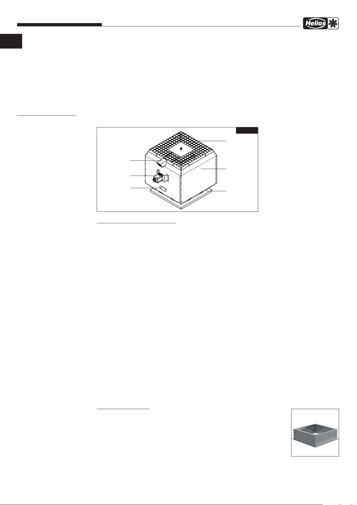
Abb.6
Ausblasseitiges
Schutzgitter
Kühlluftansaugung
Gehäuse
Revisionsschalter
Öffnung zur
Drehrichtungskontrolle
Grundplatte
mit Einströmdüse
Baureihe B VD Ø 315-900 F400/F600
Der Brandgas-Dachventilator ist ein direktangetriebener Ventilator bei dem ein IEC-Drehstrom-Motor außerhalb des
Luftstroms in einer Motorkapselung sitzt. Im Lüftungs- und Brandfall (Mindestdrehzahl beachten) erfolgt die Belüftung
der Motorkapselung automatisch. Die Förderrichtung ist über den Motor blasend. Der Strömungsverlauf ermöglicht
eine verlustarme, geradlinige Luftführung und sorgt für einen hohen Wirkungsgrad des Ventilators.
Das Radial-Laufrad mit acht räumlich gekrümmten Schaufeln besteht aus pulverbeschichtetem Stahlblech. Die dynamische Auswuchtung erfolgt nach DIN ISO 21940 Teil 11, Wuchtgüte G 6.3.
Automatische Außenluftansaugung über integrierten Kühlluftkanal, für maximale Kühlwirkung des Antriebsmotors
im Entrauchungsbetrieb (Mindestdrehzahl beachten). Grundplatte mit Einströmdüse zum direkten Aufsetzen auf
Flachdachsockel, Typ B FDS. Werkseitig montierte Gewindebolzen zur einfachen Befestigung von saugseitigem
Zubehör. Ausblasseitiges Schutzgitter aus Aluminium. Serienmäßige Transportösen für Transport und Positionierung.
Vorbereitete Gewindebolzen an der Motortrageplatte, zur Montage von ausblasseitigem Zubehör (z.B. Deflektor, Typ
B DEF oder Haubenschalldämpfer, Typ B HSDV).
Verschließbare Kontrollöffnung im Gehäuse, als Drehrichtungskontrolle bei Inbetriebnahme. Ab Ventilatorbaugröße 560
serienmäßige Ösen als Anschlagpunkte am Ventilatorgehäuse, für bauseitige Abspannvorrichtung zum Schutz bei hoher Windlast. Modularer Gehäuseaufbau für leichte Zugänglichkeit und minimalen Wartungsaufwand. Schneelastklasse
SL 0, für Schneelastklasse SL 3000 ist ein Deflektor (Zubehör) zu verwenden. Gehäuse aus seewasserbeständigem
Aluminium. Grundplatte mit Einströmdüse, Motorträger und Motorkapselung aus pulverbeschichtetem Stahlblech in
Farbe RAL 7015 (Schiefergrau) und Korrosionsschutzklasse C2. Direkt angetriebenes Hochleistungs-Radiallaufrad mit
rückwärts gekrümmten Schaufeln, einseitig saugend. Ausführung aus pulverbeschichtetem Stahlblech. Vibrationsfreier
Lauf durch dynamische Wuchtung nach Gütestufe G 6.3.
Effizienter IE3 Brandgasmotor für den Einsatz bei hohen Umgebungstemperaturen. Der Motor befindet sich außerhalb
des Luftstroms in einer automatisch belüfteten Motorkapselung. Schutzart IP55. Motorwicklung in Isolationsklasse
F. Serienmäßige Kaltleiter als Motorschutz für Lüftungsbetrieb (Motorschutzeinrichtungen sind im Brandfall für max.
Betriebsdauer automatisch außer Betrieb zu setzen), herausgeführt auf Revisionsschalter. Antriebsmotor abgestimmt
auf Betrieb mit Frequenzumrichter.
Zubehör:
Flachdachsockel B FDS:
− Zum Aufsetzen von Brandgas-Dachventilatoren der Temperaturklasse F400 und F600.
− Waagrechte Montage auf Flachdächer.
− Ausführungen mit Bauhöhe 300 mm und 500 mm verfügbar.
− Aus Stahlblech, wettersicher und stabil. Oberfläche pulverbeschichtet in RAL 7015,
Korrosionsschutzklasse C2.
− Mit 125 mm umlaufend breitem Einkleberand inkl. Bohrungen für einfache Montage.
− Vier Gewindebolzen zur Befestigung des Dachventilators.
− 40 mm dicke abriebfeste schall- und wärmedämmender Isolierung aus feuerwiderstands fähiger, elastischer Steinwolle. Kaschierung der Isolierung durch ein umlaufenes Lochblech.
6

Montage- und Betriebsvorschrift
B VD – Brandgas-Dachventilatoren F400/F600
DE DE
Schalldämpfereinsatz für Flachdachsockel B SSD:
− Schalldämpfereinsatz mit Kulissen zum Einsetzen in den Flachdachsockel, für saugseitige
Geräuschdämpfung von Brandgas-Dachventilatoren der Temperaturklasse F400 und F600
− Durchschnittlicher Dämpfungswert = 9 dB.
− Speziell abgestimmt zur Verwendung mit Flachdachsockel B FDS der Bauhöhe 300 mm
und 500 mm.
− Schalldämpfereinsatz aus Stahlblech mit abgehängten Kulissen. Oberfläche sendzimir verzinkt. 80 mm breite Kulissen mit abriebfester Isolierung aus feuerwiderstandsfähiger,
elastischer Steinwolle. Kaschierung des Dämmstoffs durch Lochblech.
− Montage von saugseitigem Zubehör an Grundplatte von Ventilator nicht möglich
bei der Verwendung von B SSD.
Deflektor B DEF:
− Zum Aufsetzen auf Brandgas-Dachventilatoren der Temperaturklasse F400 und F600 für
Schneelastklasse SL 3000.
− Befestigung mittels Montageprofilen an der Ausblasseite.
− Aus Aluminium, walzblank. Vier Montageprofile aus Stahlblech, Oberfläche pulverbeschich tet in RAL 7015, Korrosionsschutzklasse C2.
− Verhindert zuverlässig das Eindringen von Schnee und Hagel in den Ventilator.
− Keine gleichzeitige Verwendung mit Haubenschalldämpfer B HSDV möglich.
Haubenschalldämpfer B HSDV:
− Haubenschalldämpfer mit Innenkern zum Aufsetzen auf Brandgas-Dachventilatoren der
Temperaturklasse F400 und F600.
− Durchschnittlicher Dämpfungswert = 8 dB.
− Befestigung mittels Montageprofilen an der Ausblasseite.
− Aus Aluminium, walzblank. Vier Montageprofile aus Stahlblech, Oberfläche pulverbeschich tet in RAL 7015, Korrosionsschutzklasse C2.
− Abriebfeste Isolierung aus feuerwiderstandsfähiger, elastischer Steinwolle. Kaschierung des
Dämmstoffs durch Lochblech.
− Keine gleichzeitige Verwendung mit Deflektor B DEF möglich.
m
m
WARNUNG
nm
WARNUNG
3.1 Montage – Einbau
m Der Ventilator kann beim Aufstellen/Auspacken kippen und Gliedmaßen quetschen.
Transportskizze und Schwerpunkt beachten (s. Kapitel 2.2 Transport)!
m Bei der Montage kann man sich an scharfen Kanten schneiden.
Sicherheitsschuhe und Handschuhe tragen.
m Durch das rotierende Laufrad können Gliedmaßen verletzt werden.
Die Installation muss so ausgeführt werden, dass ein Eingriff auf der Saugseite nicht möglich ist (z.B. durch Rohrleitung,
Schutzgitter, ausreichende Höhe über dem Boden).
Alle Vorschriften der Arbeitssicherheit, Aufstellbedingungen und Leistungserklärungen sind bei der Montage und dem
Einbau zu beachten! Die Entrauchungsventilatoren müssen so aufgestellt und installiert werden, dass eine Inspektion,
Wartung und Instandsetzung einfach und sicher durchgeführt werden kann.
Aufstellbedingungen
VA: Für „vertikale Aufstellung” geeignet, keine Antriebsachsenneigung zulässig.
LB: Für „Lüftungsbetrieb” -20 °C bis +60 °C.
IF: „Im Freien”, wenn sichergestellt ist, dass kein Niederschlag in den Entrauchungsventilator eindringen kann.
BG: Nur über beheizten Räumen.
ND: Aufstellung nur auf einem Dach.
3.2 Dachmontage
m Die in Kapitel 1 und 2 aufgeführten Sicherheitshinweise sind zu beachten!
m Nicht unter der schweren Last aufhalten!
m Bei Arbeiten auf Dächern oder an Absturzkanten müssen geeignete Maßnahmen zur Absturzsicherung
getroffen werden.
Den Flachdachsockel mit einem geeigneten Kran auf das Dach heben (Gewichtsangaben beachten). Den
Flachdachsockel über dem Deckendurchbruch auf die Rohdecke des Flachdachs aufsetzen. Anschließend in
der Dachflucht so ausrichten, dass der umlaufende Einkleberand waagerecht ist. Dachbeschichtung vollflächig
über Einkleberand des Sockels laufen lassen und mit Bitumen-Faserkitt abdichten. Dachsockel mit der Rohdecke
des Flachdachs durch die vorhandenen Bohrungen fest verschrauben. Anschließend bauseits die notwendigen
Isolierungsarbeiten (Dämmung, Abdichtung, Dampfsperre etc.) vornehmen (s. Abb. 7).
Beim Einbau darauf achten, dass die Zugänglichkeit gewärleistet bleibt. Deckenausschnitt/-durchbruch innen
falls erforderlich verkleiden.
7
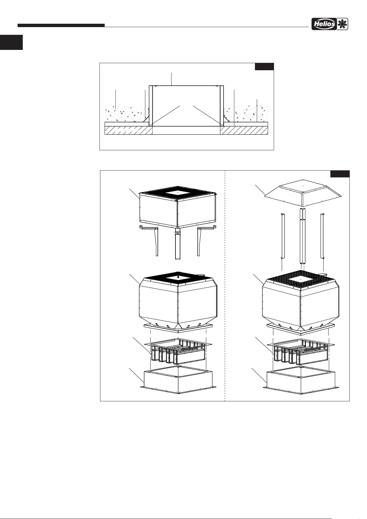
Montage- und Betriebsvorschrift
B VD – Brandgas-Dachventilatoren F400/F600
Beispielhafter Aufbau zur Montage auf Flachdach:
Flachdachsockel B FDS
Dämmkeil
Dämmung
Rohbetondecke
Verschraubung von
B FDS mit Rohbetondecke
Dachdurchbruch
DampfsperreBekiesung
ß
Übersicht Brandgas-Dachventilator B VD.. mit Zubehörteilen:
Haubenschalldämpfer
B HSDV
Abb.7
Bitumen (Abdichtung)
Abb.8
Deflektor
B DEF
BrandgasDachventilator
B VD
Schalldämpfer
-einsatz
B SSD
Flachdachsockel
B FDS
BrandgasDachventilator
B VD
Schalldämpfer
-einsatz
B SSD
Flachdachsockel
B FDS
B FDS:
− Brandgas-Dachventilator auf Flachdachsockel aufsetzen.
− Darauf achten, dass die vier Gewindebolzen in den Ecken des Flachdachsockels sauber durch die vorgesehenen
Bohrungen in der Grundplatte geführt werden.
− Brandgas-Dachventilator mit Flachdachsockel verschrauben, Unterlegscheiben und Muttern liegen
Flachdachsockel bei.
− Empfohlene Anzugsdrehmomente in Kapitel 3.7 beachten.
B SSD:
− Schalldämpfereinsatz in Flachdachsockel einsetzen.
− Darauf achten, dass die vier Gewindebolzen in den Ecken des Flachdachsockels sauber durch die vorgesehene
Bohrungen im Tragrahmen des Schalldämpfereinsatzes geführt werden.
− Brandgas-Dachventilator auf Flachdachsockel aufsetzen, Schalldämpfereinsatz wird gemeinsam mit Ventilator ver schraubt.
− Empfohlene Anzugsdrehmomente in Kapitel 3.7 beachten.
8

Montage- und Betriebsvorschrift
B VD – Brandgas-Dachventilatoren F400/F600
DE DE
B DEF:
− Ausblasseitiges Schutzgitter von Brandgas-Dachventilator abschrauben und entfernen.
− Vorgeprägte Stege im ausblasseitigen Schutzgitter für Füße vom Deflektor mit Seitenschneider o.Ä. heraustrennen.
− Jeweils beide Muttern (bzw. Augenschrauben ab BG 450) an den Ecken der Motortrageplatte entfernen (werden
wieder benötigt).
− Füße des Deflektors von oben in Ventilator einführen.
− Füße in den Ecken der Motortrageplatte auf die Gewindebozen stecken und mit der Motortrageplatte verschrauben
(demontierte Muttern aus Schritt 3 und ab BG 450 die zwei im Polybeutel beigelegten Muttern verwenden).
− Ausblasseitiges Schutzgitter des Brandgas-Dachventilators wieder anschrauben, Füße des Deflektors werden
durch die Aussparung in den Stegen (s. Schritt 2) geführt.
− Haube des Deflektors auf die vier Füße montieren, beiliegendes Befestigungsmaterial verwenden.
− Empfohlene Anzugsdrehmomente in Kapitel 3.7 beachten.
B HSDV:
− Ausblasseitiges Schutzgitter von Brandgas-Dachventilator abschrauben und entfernen.
− Jeweils beide Muttern (bzw. Augenschrauben ab BG 450) an den Ecken der Motortrageplatte entfernen (werden
wieder benötigt).
− Füße von Haubenschalldämpfer von oben in Ventilator einführen.
− Füße in den Ecken der Motortrageplatte auf die Gewindebozen stecken und mit der Motortrageplatte verschrauben
(demontierte Muttern aus Schritt 3 und ab BG 450 die zwei im Polybeutel beigelegten Muttern verwenden).
− Haubenschalldämpfer auf die vier Füße montieren, beiliegendes Befestigungsmaterial verwenden.
− Sofern erforderlich (lokale Windlast prüfen) ab Baugröße 630 mit bauseitiger Abspannung gegen hohe
Windgeschwindigkeiten sichern, s. Kapitel 3.3.
− Empfohlene Anzugsdrehmomente in Kapitel 3.7 beachten.
Anschluss der Entrauchungsleitungen mit weiterem Montagezubehör:
Segeltuchstutzen STSB:
Für den saugseitigen Anschluss der Entrauchungsventilatoren an Entrauchungsleitungen sind Segeltuchstutzen (elastische Gewebestutzen) STSB... F400 bzw. F600 zu verwenden. Bei der Montage der Segeltuchstutzen ist darauf zu
achten, dass die Einbaulücke von 145 mm eingehalten wird und so eine Belastung auf Zug bzw. auf Stauchung vermieden wird. Die elastischen Verbinder nicht versetzt einmontieren. So wird verhindert, dass es zu Leistungsminderung
und auch Geräuschentwicklung kommt.
Verlängerungsrohr VR:
Beim Einbau in Rohrstrecken ist darauf zu achten, dass vor dem Ventilator eine ausreichend lange gerade Rohrstrecke
2,5 x Durchmesser (z.B. mit Verlängerungsrohr VR...) vorgesehen wird, da sonst mit erheblichen Leistungsminderungen
und Geräuscherhöhung zu rechnen ist.
Rohrschalldämpfer RSD:
Rohreinbau mit saugseitigem Rohrschalldämpfer RSD... F400. Der saugseitige Rohrschalldämpfer muss am Eintritt
zusammen mit einem Segeltuchstutzen montiert werden.
Rohrverschlussklappe RVS:
Selbsttätige Rohrverschlussklappe RVS... F600 mit Federrückstellung:
Horizontal in jede Richtung, vertikal mit Durchströmung nach oben einbaubar.
Bei vertikaler Luftführung muss die Federückstellung an der RVS ausgehängt werden.
3.3 Aufstellung
Die Aufstellung erfolgt waagerecht auf Dächern in gemäßigtem Klima bei Temperaturen im Bereich von -20 °C bis max.
+60 °C. Der Aufstellungsort muss in Art und Beschaffenheit für den Dachventilator geeignet sein. Die Unterkonstruktion
muss eben und ausreichend tragfähig sein.
Ventilatoraufstellung im Freien:
Die Brandgas-Ventilatoren vom Typ B VD sind in der Einbauanordnung für vertikale Luftförderrichtung für den Einsatz
unter normalen Witterungsbedingungen im Freien, wie sie üblicherweise vorherrschen, geeignet. Das Eindringen von
Niederschlagswasser in den Brandgas-Ventilator ist zulässig, dieses muss jedoch ungehindert aus dem Gehäuse ablaufen können. Bei extremen, unwetterartigen Bedingungen kann es in seltenen Fällen zum Eintritt von Niederschlag in
das Gebäude kommen. Besondere Einbaubedingungen und Standorte, wie z.B. Küstennähe oder hohe freistehende
Gebäude, können diese Umstände begünstigen.
Besonders der Bereich der Ansaugöffnungen ist durch den Anbau von Verlängerungsrohren oder Schutzgittern zu
schützen. Die Unterkonstruktion muss eben und ausreichend tragfähig sein.
Das Eindringen von Schnee in den Brandgas-Dachventilator ist zu verhindern. Je nach lokaler Aufstellsituation ist
ein Deflektor (Zubehör) erforderlich. Die Brandgas-Dachventilatoren erfüllen im Standard die Anforderungen an die
Schneelast nach SL 0. Durch Aufsetzen eines Deflektors (B DEF) auf den Brandgas-Dachventilator werden die
Anforderungen an die Schneelastklasse SL 3000 erfüllt.
ACHTUNG
m Bei Windgeschwindigkeiten >150 km/h können Bauteile des Ventilators verformt, zerstört und weggeschleudert werden.
Der Ventilator darf nur an Orten aufgestellt werden, an denen Windgeschwindigkeiten von 150 km/h nicht überschritten werden. Ggf. sind zusätzliche Sicherungsmaßnahmen zu treffen.
Serienmäßig verfügen die Brandgas-Dachventilatoren der Baugröße 630 bis 900 über vier lose beigelegte
Augenschrauben. Diese können bei Bedarf auf allen vier Seiten am Gehäuse in die Gewinde der Befestigungsschrauben
9

Montage- und Betriebsvorschrift
B VD – Brandgas-Dachventilatoren F400/F600
des ausblasseitigen Schutzgitters eingedreht werden.
In keinem Fall dürfen diese Augenschrauben als Anschlagpunkte zum Anheben des Ventilators verwendet
werden. Anschlagpunkte sind mit einem Hinweisaufkleber separat gekennzeichnet, s. Kapitel Transport.
Der Haubenschalldämpfer B HSDV verfügt serienmäßig bei allen Baugrößen über vier montierte Augenschrauben.
Diese Augenschrauben am Ventilator und am Haubenschalldämpfer können bei Bedarf zur bauseitigen Abspannung
bei hohen Windlasten genutzt werden. Die Notwendigkeit zur bauseitigen Abspannung ist im Einzelfall in Abhängigkeit
der lokal auftretenden Windeinflüsse zu prüfen.
Der Installateur muss den Ventilator an den vorgesehen Anschlagpunkten abspannen, wenn mit solchen
Umwelteinflüssen zu rechnen ist. Die Windlast ist gemäß DIN EN DIN EN 1991-1-4 zu berechnen.
Abb.9
BrandgasDachventilator
B VD
Flachdachsockel
B FDS
RVS Federn
Segeltuchstutzen
STSB
Verlängerungsrohr
VR
Montagering
MRV
Ansaugdüse mit
Schutzgitter
ASD-SGD
Rohrverschlussklappe
RVS
Schwingungsdämpfer
für Zugbelastung
SDZ
Schwingungsdämpfer
für Druckbelastung
SDD
Diffusor
DIF
m
WARNUNG
3.4 Lager-Zustandsdiagnostik
Type: LZD-Basic und LZD-Comfort
Die Helios Lager-Zustandsdiagnostik dient der sicheren Überwachung der Funktionsfähigkeit von Motorlagern im
Antriebsmotor des Entrauchungsventilators. Das System ermöglicht wahlweise durch stetige oder gelegentliche
Überwachung der Lagerzustände die frühzeitige Erkennung von sich anbahnenden Lagerschäden. Eine Auswechslung
der Lager erfolgt nicht periodisch, sondern in Abhängigkeit des tatsächlichen Verschleißes. Hierzu ist der Prüf- und
Wartungsplan in dieser Montage- und Betriebsvorschrift zu beachten. Vor Betrieb und Einsatz der Lager-Zustandsdiagnostik ist die separate MBV des Überwachungssystems zu beachten.
Angaben zu weiterem Brandgas-Zubehör sind aus dem Internet (www.heliosselect.de), Hauptkatalog bzw. den Helios
Verkaufsunterlagen zu entnehmen.
3.5 Mindestluftspalte bei Einhaltung der Werkstoffpaarungen
m Verletzungsgefahr!
Laufrad von Hand bewegen um den Freilauf zu überprüfen!
Vor dem Einbau den Mindestluftspalt zwischen Innenseite des Radiallaufrads und der Düsenaußenseite nach folgender
10

Montage- und Betriebsvorschrift
Luftspalt X
DETAIL A
MAßSTAB 1 : 5
DETAIL A
MAßSTAB 1 : 5
B VD – Brandgas-Dachventilatoren F400/F600
DE DE
Tabelle prüfen:
Type TK Mindestluftspalt X (mm)
B VDD 315 F400/F600 2,5
B VDD 355 F400/F600 3,0
B VDD 400 F400/F600 3,5
B VDD 450 F400/F600 3,5
B VDD 500 F400/F600 4,0
B VDD 560 F400/F600 4,5
B VDD 630 F400/F600 5,0
B VDD 710 F400/F600 5,5
B VDD 800 F400/F600 6,5
B VDD 900 F400/F600 7,0
Abb.10
Luftspalt X
A
Entsprechen die festgestellten Werte nicht den Sollmaßen, darf der Ventilator nicht eingebaut bzw. betrieben
werden. Bei Fragen bitte den Helios Kundendienst „TGA” kontaktieren.
3.6 Maximal zulässige Schwingungsgrenzwerte gemäß ISO 14694 / ISO 10816-3
– Schwingungswächter
Bei Verwendung von Schwingungswächtern dürfen diese den Brandgasventilator im Entrauchungsfall nicht
abschalten!
max. zulässige Schwingungsgrenzwerte bei einer Lüfterleistung < 75 kW
Inbetriebnahme Alarm Abschalten
fest montiert flexibel aufgestellt fest montiert flexibel aufgestellt fest montiert flexibel aufgestellt
[mm/s] [mm/s] [mm/s] [mm/s] [mm/s] [mm/s]
4,5 6,3 7,1 11,8 9,0 12,5
– Installation eines Schwingungswächters
Die Installation eines Schwingungswächters (bauseits) muss am Gehäuse des Ventilators erfolgen und darf nicht in der
Drehbereichszone des Laufrads liegen.
Der Luftspalt (s. Abb. 10) darf durch die Installation des Schwingungswächters nicht beeinflusst werden!
3.7 Empfohlene Anzugsdrehmomente für Befestigungsschrauben
Folgende Anzugsdrehmomente für Verbindungen von Befestigungsschrauben und -muttern sind zu verwenden:
Anzugsdrehmoment für Schrauben
Schraubengröße
Sechskantschraube
verzinkt
Sechskantschraube
verzinkt
Sechskantschraube
edelstahl
Festigkeit 8.8 Festigkeit 10.9 A2/A4 Festigkeit A70
M5 6 Nm 9,5 Nm 5,1 Nm
M6 10 Nm 16,5 Nm 9 Nm
M8 25 Nm 40 Nm 22 Nm
M10 49 Nm 79 Nm 44 Nm
M12 85 Nm 137 Nm 74 Nm
M16 210 Nm 338 Nm 183 Nm
11
Montage- und Betriebsvorschrift
m
WARNUNG
3.8 Elektrischer Anschluss
m
WARNUNG
m Lebensgefahr durch einen elektrischen Schlag!
vom Netz zu trennen und gegen unerwünschtes Wiedereinschalten zu sichern!
B VD – Brandgas-Dachventilatoren F400/F600
Vor allen Wartungs- und Installationsarbeiten oder vor Öffnen des Revisionsschalters ist das Gerät allpolig
− Der elektrische Anschluss darf nur von einer autorisierten Elektrofachkraft entsprechend den Angaben im
Revisionsschalter und den beiliegenden Anschlussplänen ausgeführt werden.
− Die einschlägigen Normen, Sicherheitsbestimmungen (z.B. DIN VDE 0100) sowie die TAB der EVUs sind unbe-
dingt zu beachten.
− Die Angaben zu „Elektrische Leitungsanlagen” sind zu beachten.
− Die Angaben zu „Auslöseeinrichtungen” sind zu beachten.
− Der elektrische Anschluss muss so ausgeführt werden, dass der Ventilator im Entrauchungsfall
bis zum elektromechanischen Ausfall, bei vorgesehener Drehzahl betrieben wird. Hierfür ist je de Art von Motorschutz, Luftströmungswächter, Schwingungswächter im Entrauchungsfall zu überbrücken
und darf nicht zur Abschaltung des Ventilators führen.
− Anschlussdaten müssen mit den An gaben des Motorleistungsschildes übereinstimmen.
− Die Einführung der Zuleitung ist fachgerecht auszuführen! Die Anschlussleitung in den Revisionsschalter muss die
event. auftretenden Schwingungen des Ventilators ausgleichen.
− Leitung nie über scharfe Kanten führen.
− Sicherheitsbauteile, z.B. Schutzgitter, Abdeckungen und Verschlüsse dürfen weder demontiert noch umgangen
oder außer Funktion gesetzt werden.
− Weitere Arbeitsgänge siehe nachfolgenden Abschnitt „Inbe triebnahme“.
− Erdverbindungen, einschließlich zusätzlicher Potentialausgleichanschlüsse sind ordnungsgemäß zu installieren!
l
nmr
3.9 Inbetriebnahme
m Das rotierende Laufrad kann Ihre Finger/Gliedmaßen verletzen.
Vor der Inbetriebnahme Berührungsschutz sicherstellen!
Beim Prüfen der Drehrichtung eine Schutzbrille tragen!
Geeignete Schutzausrüstung tragen.
Folgende Kontrollarbeiten sind vor der Erstinbetriebnahme auszuführen bzw. zu prüfen:
− Die Transportsicherung muss vor der Funktionsprüfung entfernt werden!
− Bestimmungsgemäßen Einsatz des Ventilators über prüfen.
− Zulässige Fördermitteltemperatur überprüfen.
− Netzspannung mit Leistungsschildangabe vergleichen:
− Ventilator auf solide Befestigung und fachgerechte elektrische Installation prüfen, ggf. Brücken im elektrischen
Anschluss überprüfen.
− Alle Teile, insbesondere Schrauben, Muttern, Schutzgitter auf festen Sitz überprüfen. Schrauben dabei nicht lösen!
− Freilauf des Laufrades prüfen.
− Mindestluftspalte laut Tabelle in Kapitel 3.5 prüfen.
− Sicherstellen, dass der Ansaug- und Ausblasbereich nicht für Personen zugänglich ist.
− Übereinstimmung der Dreh- und Förder rich tung.
− Sichtkontrolle auf vergessene oder lose Teile durchführen.
− Stromaufnahme mit Leistungsschildangabe vergleichen.
− Motorschutzeinrichtung auf Funktion testen, Überbrückung im Brandfall überprüfen!
− Schutzleiteranschluss prüfen.
− Abdichtung des Anschlusskabels in den Revisionsschalter und festen Klemm sitz der Adern prüfen.
− Inbetriebnahme darf nur erfolgen, wenn der Be rührungsschutz sichergestellt ist.
− Dichtheit aller Verbindungen prüfen (falls erforderlich).
− Montagerückstände aus Ventilator bzw. Kanal entfernen.
− Beim Probelauf den Ventilator auf unzulässige Vibrationen und Geräusche prüfen.
− Den Ventilator nicht außerhalb der angegebenen Kennlinie (siehe Katalog / Internet) betreiben. Der Ventilator muss
auf seinem vorgeschriebenen Betriebspunkt laufen.
− Das beigelegte Inbetriebnahmeprotokoll (siehe Seite 20) ausfüllen und im Gewährleistungsfall vorlegen.
− Das beigelegte Inbetriebnahmeprotokoll ist dem Anlagenbetreiber ausgefüllt auszuhändigen.
3.10 Betrieb
Regelmäßig die einwandfreie Funktion des Ventilators prüfen:
− Freilauf des Laufrades
− Prüfung des Luftspaltes (siehe Tabelle in Kapitel 3.5)
− Messen der Stromaufnahme
− Prüfung auf eventuelle Schwingungen und Geräusche
− Ablagerungen von Staub und Schmutz im Gehäuse bzw. am Motor und Laufrad
Hinsichtlich Funktionserhalt und Verlegung der elektr. Leitungsanlagen gelten die einschlägigen Vorschriften
des VDE-Regelwerkes sowie die landesrechtlichen Vorschriften, insbesondere der „Richtlinie über brandschutz technische Anforderungen an Leitungsanlagen“. Der Ventilator muss während der vorgesehenen
Entrauchungsdauer funktionsfähig bleiben (Funktionserhalt).
12

Montage- und Betriebsvorschrift
KAPITEL 4
INSTANDHALTUNG UND
WARTUNG
m
GEFAHR
4.0 Instandhaltung und Wartung
nmr
Motoren mit Nachschmiereinrichtung nach Angaben auf dem Motortypenschild schmieren!
Nur vorgeschriebene Fette sind zulässig!
B VD – Brandgas-Dachventilatoren F400/F600
DE DE
Lebensgefahr durch einen elektrischen Schlag!
m
Durch das rotierende Laufrad können Gliedmaßen verletzt werden.
m
Vor allen Wartungs- und Installationsarbeiten oder vor Öffnen des Revisionsschalters ist das Gerät allpolig vom Netz zu
trennen und gegen unerwünschtes Wiedereinschalten zu sichern! Geeignete Schutzausrüstung tragen.
− Übermäßige Ablagerungen von Schmutz, Staub, Fetten u.a.m. auf Laufrad, Motor, Schutzgitter und vor allem zwi schen Einströmdüse und Laufrad sind unzu lässig und durch periodische Reinigung zu unterbinden.
− Eine Funktionsprüfung ist in max. sechsmonatigem Abstand, im Falle längeren Stillstands bei Wiederinbetriebnahme,
durchzuführen.
− Die Wartung ist 1 mal jährlich, anderenfalls bei Wiederinbetriebnahme durchzuführen.
− Instandhaltungs- und Wartungsarbeiten dürfen nur von Fachkräften laut Kapitel 1.6 durchgeführt werden.
− Wartung anhand des Prüf- und Wartungsplans in Kapitel 7 durchführen.
− Zu prüfen sind:
• Schraubverbindungen insbesondere Laufradbefestigung. Schrauben dabei nicht lösen!
• Gehäuse-/Laufradoberflächenbeschichtung (z.B. auf Rost, Lackschäden)
• Lagergeräusche
• Beschädigungen
• Schwingungen, Vibrationen
• Schmutzablagerungen
• Stromaufnahme
• Funktion der Sicherheitsbauteile
• Motorschmierung/Motorlager
Die Brandgasventilatoren mit Motor-Baugröße 160 bis 250 haben Schmiernippel und müssen nach Angaben auf
dem Motortypenschild geschmiert werden.
− Es wird empfohlen ein Anlagenwartungsbuch zu führen und die durchgeführten Prüfungen und Prüfungsergebnisse
einzutragen. Die Ergebnisse mit den Ergebnissen aus früheren Prüfungen vergleichen. Sollten die Parameter abwei chen, unbedingt Kontakt mit dem Hersteller aufnehmen.
− Die Anweisungen aus der Wartungsanleitung des Elektromotorherstellers müssen beachtet werden!
− Der Entrauchungsventilator muss nach erfolgtem Entrauchungsbetrieb entsorgt werden!
− Ein erneuter Einsatz ist in keinem Fall zulässig!
m
WARNUNG
nm
4.1 Reinigung
m
Vor Beginn der Reinigung Ventilator allpolig vom Netz trennen und gegen Wiedereinschalten sichern!
Geeignete Schutzausrüstung tragen.
4.2 Reparatur
Eigene Reparaturversuche sind untersagt
Die Reparatur von Brandgasventilatoren darf nur durch Rücksendung ins Werk erfolgen!
Helios Kundendienst kontaktieren.
Durch einen Isolationsfehler können Sie einen elektrischen Schlag bekommen!
– Durchströmungsbereich, Laufrad, Verstrebung und Motor des Ventilators säubern.
– Regelmäßige Inspektion, ggf. mit periodischer Reinigung ist erforderlich um Unwucht durch Verschmutzung zu ver-
meiden. Durchströmungsbereich des Ventilators säubern.
– Keine aggressiven, lacklösenden Mittel verwenden!
– Hochdruckreiniger oder Strahlwasser ist nicht gestattet!
13

Montage- und Betriebsvorschrift
4.3 Hinweise – Störungsursachen
Fehler/Problem Mögliche Ursachen Mögliche Lösungen Personalqualifikation
B VD – Brandgas-Dachventilatoren F400/F600
Ventilator startet nicht – keine Spannung,
Sicherung löst aus – Erd-/Windungsschluss im Motor Motor ersetzen Hersteller
Fehlerstromschutzschalter löst aus
Motorschutzschalter
löst aus
streifendes Laufrad – starke Verschmutzung reinigen Unterwiesenes Personal
Falsche Förderrichtung
Vibrationen – Verschmutzung reinigen Unterwiesenes Personal
Anormale Geräusche – falscher Betriebspunkt Eignung des Ventilators prüfen, Zu- und
zu hohe Stromaufnahme
Ventilator bringt die
Leistung (Drehzahl)
nicht
fehlen einer Phase
– Laufrad blockiert Blockade lösen, reinigen, ggf. Laufrad ersetzen Fachkraft laut 1.6 / Hersteller
– Motor blockiert Motor prüfen, ggf. ersetzen Elektrofachkraft / Hersteller
– Zuleitung / Anschluss
beschädigt
– falsch angeschlossen Anschluss überprüfen, ändern Elektrofachkraft
– beschädigte Motorisolation Motor ersetzen Hersteller
– beschädigte Zuleitungsisolation Zuleitung erneuern Elektrofachkraft
– schwergängige Lager Lager ersetzen Hersteller oder vom Hersteller
– streifendes Laufrad siehe streifendes Laufrad
– falscher Betriebspunkt Eignung des Ventilators prüfen, Zu- und
– Laufrad beschädigt Laufrad ersetzen Hersteller
– Gehäuse beschädigt Gehäuse ersetzen Hersteller
– Laufrad nicht mittig Helios Kundendienst kontaktieren
– falscher Anschluss Anschluss prüfen/ändern Elektrofachkraft
– Lagerschäden Lager ersetzen Hersteller oder vom Hersteller
– falscher Betriebspunkt Eignung des Ventilators prüfen, Zu- und
– befestigungsbedingte Resonanz Befestigung prüfen/ausbessern Fachkraft laut 1.6
– streifendes Laufrad siehe streifendes Laufrad
– Lagerschäden Lager ersetzten Hersteller oder vom Hersteller
– mechanische Beschädigung Wartung durchführen Fachkraft laut 1.6
– falscher Betriebspunkt Eignung des Ventilators prüfen,
– streifendes Laufrad siehe streifendes Laufrad
– Lagerschäden Lager ersetzten Hersteller oder vom Hersteller
– Unzureichende Luftförderung Zu- und Abströmung prüfen/freihalten.
– falsche Spannung Anschluss prüfen/ändern Elektrofachkraft
– Lagerschäden Lager ersetzen Hersteller oder vom Hersteller
– Verschmutzung reinigen Unterwiesenes Personal
– unzureichende Nachströmung Mindestabstand ansaugseitig berücksichtigen Fachkraft laut 1.6
Netzspannung prüfen
Anschluss nach Schaltplan überprüfen
Teile erneuern, ggf. Motor ersetzen Hersteller
Abströmung prüfen/freihalten
Abströmung prüfen/freihalten
Abströmung prüfen/freihalten
Zu- und Abströmung prüfen/freihalten
Betriebspunkt feststellen (Luftmenge + AnlagenDruckverlust) und mit Ventilatorkennlinie abgleichen
Elektrofachkraft
autorisierte Fachfirma
Fachkraft laut 1.6
autorisierte Fachfirma
Fachkraft laut 1.6
Fachkraft laut 1.6
autorisierte Fachfirma
Fachkraft laut 1.6
autorisierte Fachfirma
Fachkraft laut 1.6
autorisierte Fachfirma
14
Montage- und Betriebsvorschrift
4.4 Ersatzteile
4.5 Stilllegen und Entsorgen
m
WARNUNG
nm
B VD – Brandgas-Dachventilatoren F400/F600
DE DE
Defekte Ventilatoren sind komplett zu tauschen. Eigene Reparaturversuche sind in keinem Fall zulässig!
Der defekte Entrauchungsventilator ist komplett in das Werk der Firma Helios Ventilatoren zurück zu senden!
Eine optimale Betriebssicherheit der Ventilatoren ist nur durch Helios Ersatzteile und bei Reparaturen durch den
Hersteller gewährleistet.
Gefahr von Personenschäden!
m
Bei der Demontage können durch einen unbeabsichtigten Anlauf des Ventilators Gliedmaßen/Finger gequetscht, eingezogen, gefangen oder abgetrennt werden.
Bei der Demontage können Gliedmaßen zwischen Bauteilen verletzt werden.
− Vor der Demontage muss das Gerät vom Stromnetz getrennt sein.
− Sicherheitsschuhe und Handschuhe tragen.
− Bei der Demontage eines B VD und montiertem druckseitigem Zubehör (B DEF und B HSDV) zum
Transport nicht an den Anschlagpunkt des Zubehörs anschlagen.
− Beim Anheben der Last kann diese durch falsches Anschlagen herunterfallen
m
GEFAHR
KAPITEL 5
TECHNISCHE DATEN
5.0 Technische Daten
Schutzart: Motor: IP55
Isolationsklasse Motorwicklung: F
Temperaturklasse: F400, F600
Lebensgefahr durch Stromschlag!
m
Bei der Demontage werden spannungsführende Teile freigelegt, die bei Berührung zu einem elektrischen Schlag führen. Vor der Demontage Ventilator allpolig vom Netz trennen und gegen Wiedereinschalten sichern!
Die allgemein gültigen Arbeitsschutz- und Unfallverhütungsvorschriften sind einzuhalten!
Elektroarbeiten dürfen nur von einer autorisierten Elektrofachkraft durchgeführt werden.
− Elektroanschluss allpolig vom Netz trennen
− Geeignete Hebewerkzeuge und Befestigungsvorrichtungen zum Demontieren des Ventilators verwenden
− Zur Stilllegung des Motors, Anweisungen aus der Wartungsanleitung des Elektromotors beachten
− Die Ventilatorkomponenten entsprechend den gültigen Vorschriften und Gesetzen entsorgen
Max. Fördermitteltemperatur: s1 = -20 °C bis +120 °C
s2 = 400 °C/120 Min. und
600 °C/120 Min.
Max. Gewichte:
Type
B VDD 315/4 F400/F600 56 12 20 20 28 8
B VDD 315/6 F400/F600 56 12 20 20 28 8
B VDD 355/4 F400/F600 61 13 24 22 31 9
B VDD 355/6 F400/F600 61 13 24 22 31 9
B VDD 400/4 F400/F600 74 16 28 22 31 9
B VDD 400/6 F400/F600 72 16 28 22 31 9
B VDD 450/4 F400/F600 93 19 34 26 35 11
B VDD 450/6 F400/F600 83 19 34 26 35 11
B VDD 500/4 F400/F600 122 24 42 31 45 18
B VDD 500/6 F400/F600 113 24 42 31 45 18
B VDD 560/4 F400/F600 147 29 51 31 45 18
B VDD 560/6 F400/F600 132 29 51 31 45 18
B VDD 630/4 F400/F600 231 50 60 34 48 23
B VDD 630/6 F400/F600 203 50 60 34 48 23
B VDD 710/4 F400/F600 403 64 72 53 76 36
B VDD 710/6 F400/F600 338 64 72 53 76 36
B VDD 800/4 F400/F600 611 80 92 53 76 36
B VDD 800/6 F400/F600 501 80 92 53 76 36
B VDD 900/4 F400/F600 883 116 112 59 85 39
B VDD 900/6 F400/F600 618 116 112 59 85 39
Temperatur-
klasse
Ventilator Deflektor
Gewicht bis max. [kg]
Hauben-
schall-
dämpfer
Flachdach-
sockel
300 mm
Flachdach-
sockel
500 mm
Schall-
dämpfer-
einsatz
15

Montage- und Betriebsvorschrift
m= 122 kg(A, statisch)
F600
600°C
120 min
SL0
IP 55 TN 60°C
MPA BS 0761
EN 12101-3:2015
Ventilateures extracteures des fumées et de chaleure
Maschinelle Rauch und Wärmeabzugsgeräte
Powered smoke and heatexhaust ventilators
Cert. Nr. 0761-CPR-0800 07/19
Cos φ: 0,81435 1/min
N = 64,2ŋ = 57,5%
only on top of heated
buildings
Uniquement au-dessus de
bâtiments chauffes
ND nur auf Dach möglich only for use on rooftop
Possible uni quement sur
toiture
axe verticalvertical drive shaftvertikale AchslageVA
IF
37517
MBV B VD
2019-06
CPR B VD
F600
2019-06
QR-Produkt Info
BG
nur über beheizten
Gebäuden
Montage und Betrieb nur unter Beac htung aller
Sicherheitsvorschriften (EN ISO 13857) und gem äß MBV
Nr.
Installation and operation only considering all safety
regulations (EN ISO 13857) and according to instruction
no.
Montage et fonctionnem ent dans le respect des
prescriptions de s écurité suivant (entre autres norme EN
ISO 13857) et notice d'utilis ation n°
im Freien, sofern kein
Niederschlag eindringen
kann
outside, if not exposed
to the elements
Aufstellbedingung Positioning Placement
ventilation de confort
LB
Lüftungsbetrieb comfort ventilation
I' extérieur, protégé des
inteméries
Helios Ventilatoren GmbH + Co KG
Lupfenstraße 8
78056 VS-Schwenningen
www.heliosventilatoren.de
0761
B VDD 500/4 F600
Art.Nr.: 1597-001
Auftr.Nr.: 297784
PC 09216
2019
2,2 kW
50 Hz
Y400 V 4,56 A
Isol. Kl. F
T
R
60°C
5.1 Typenschlüssel
Beispiel:
B VD D 500/4 F600
5.2 Typenschild
Beispiel:
B VD – Brandgas-Dachventilatoren F400/F600
Temperaturklasse
Polzahl Motor
Ventilator Baugröße / Nenndurchmesser
Drehstrom
Ventilator Baureihe (Brandgas-Dachventilator vertikal ausblasend)
B = Brandgas-Ausführung
5.3 Motortypenschild
Das Motortypenschild befindet sich direkt am Motor.
Technische Daten sind dem Motortypenschild zu entnehmen.
Abb.11
Zeichenschlüssel Typenschild Ventilator:
Herstelleradresse
CE-Zeichen
Ausführung:
B VDD = Typenbezeichnung; Drehstrom
500 = Baugröße
/4 = polig
F600
Artikelnummer
Seriennummer
Produktionscode
Baujahr
Technische Daten
Zulassungsnummer
Temperaturklasse/max.
Fördermitteltemperatur
Aufstellbedingungen
Referenz-Nr. der
Montage- und Betriebsvorschrift
Referenz-Nr. der Leistungserklärung
siehe Punkt 3.1
Art.-Nr., SNR (Seriennummer) und PC
(Produktionscode) Nummer identifizieren
den Ventilator eindeutig.
16

Montage- und Betriebsvorschrift
85499 022 SS-1262 18.06.19
KAPITEL 6
SCHALTPLAN-ÜBERSICHT
6.0 Schaltpläne
B VD – Brandgas-Dachventilatoren F400/F600
Die folgende Tabelle beschreibt den Ventilatoranlauf und gibt Hinweise auf die benötigte Anschlussleitung:
Spannungsangabe auf
Motortypenschild
230 / 400 V Y nein ja nein
400 / 690 V
Kundenseitiges
Anschlusskabel
Kabel Motorschutz
mit TK/PTC
*Direktanlauf vor Inbetriebnahme mit dem örtlichen Netzbetreiber abklären!
Betrieb
bei
400 V, 3~
Y/△- Anlauf P
△
– 6 + PE 3 + PE 3 + PE
– 2 2 2
≥
3,0 kW
M
ja nein ja*
Direktanlauf Y P
Eintourig
Ventilatoranlauf
2,2 kW
M ≤
Direktanlauf △P
M ≤
DE DE
2,2 kW
SS-1262
3~ Motor mit RS 6+1+2 7,5
(mit Y-Brücke)
B VD mit Nennleistung ≤ 2,20 kW
(Direktanlauf oder FU-Betrieb)
3~ Motor
M
U1
U2
1
4
1
3
5
2
4
6
V1
V2
5
7
8
9
10
W2
6
2
12 11
mit TB/TP (TK/KL)
9
W1
TB/TP
TB/TP
8
7
3
13
14
16 15
17
18
20 19
PE
RS 6+1+2 7,5
L1
L2
L3
TB/TP
TB/TP
PE
17

Montage- und Betriebsvorschrift
85499 072 SS-1307 18.06.19
85499 021 SS-1261 18.06.19
SS-1261
3~ Motor mit RS 6+1+2 7,5
B VD mit Nennleistung =
3,00 kW bis 7,50 kW (SternDreieck-Anlauf)
B VD – Brandgas-Dachventilatoren F400/F600
M
9
3~ Motor
mit TB/TP (TK/KL)
SS-1307
3~ Motor mit RS 6+1+2 15/30/45
B VD mit Nennleistung = 11,00 kW
bis 45, 00 kW (Direktanlauf oder FUBetrieb)
U1
U2
1
4
1
3
5
2
4
6
V1
V2
5
2
7
9
8
10
12 11
W2
6
13
14
W1
3
TB/TP
7
16 15
17
18
PE
TB/TP
8
20 19
RS 6+1+2 7,5
U2
U1
/
/
/
V1
V2
Bauseits
on site
sur site
W2
W1
TB/TP
TB/TP
PE
3~ Motor
PE
U1
1
V1
M
V2
U2
W1
2
4
3
5
mit TB/TP (TK/KL)
9
W2
6
TB/TP
7
TB/TP
8
1
3
5
1.1
1.3
2
4
6
1.2
U2
Bauseits
/
on site
/
sur site
/
1.4
V2
PE PE
V1
U1
PE
W1
18
1.5
1.6
W2
13
14
21
22
43
43
44
44
TB/TP
TB/TP
RS 6+1+2
(15 / 30 / 45)

Montage- und Betriebsvorschrift
85499 023 SS-1263 18.06.19
85499 071 SS-1306 18.06.19
SS-1263
3~ Motor mit RS 6+1+2 7,5
(mit △-Brücke)
B VD mit Nennleistung = 3,00 kW
bis 7,50 kW
(Direktanlauf oder FU-Betrieb)
B VD – Brandgas-Dachventilatoren F400/F600
3~ Motor
U2
4
U1
1
V2
5
V1
2
M
W2
6
mit TB/TP (TK/KL)
9
W1
TB/TP
7
3
DE DE
PE
TB/TP
8
SS-1306
3~ Motor mit RS 6+1+2
15/30/45 (mit △-Brücke)
B VD mit Nennleistung =
11,00 kW bis 45,00 kW
(Stern-Dreieck-Anlauf)
PE
1
3
2
4
7
5
6
9
8
10
13
12 11
14
16 15
17
18
20 19
RS 6+1+2 7,5
L1
L2
L3
TB/TP
TB/TP
PE
3~ Motor
U1
1
V1
2
W1
3
U2
4
M
V2
5
mit TB/TP (TK/KL)
9
W2
6
TB/TP
7
TB/TP
8
1
3
5
1.1
1.3
1.5
2
4
6
1.2
1.4
PE PE
L2
L3
19
L1
PE
1.6
13
14
21
22
43
43
44
44
TB/TP
TB/TP
RS 6+1+2
(15 / 30 / 45)

Montage- und Betriebsvorschrift
B VD – Brandgas-Dachventilatoren F400/F600
INBETRIEBNAHMEPROTOKOLLKAPITEL 7
Gemäß DIN 31051
Bitte das Inbetriebnahmeprotokoll ausfüllen.
Das Exemplar verbleibt in dieser Dokumentation. Evtl. Fragen im Zusammenhang mit der Gewährleistung lassen sich nur bei Vorlage des
-
Inbetriebnahmeprotokolls klären!
Installationsbetrieb: ..................................................................................................................................................................................
Standort/Firmensitz: ........................................................................ Tel. / E-Mail:............................................................................
Einbaudatum Bemerkungen:
Anlagenbezeichnung
Baureihe/Typ
Produktionscode
Seriennummer
Zulassungsnummer
Nenndaten
Motortyp
Motornummer
Motorschutz (z.B. KL, TK)
Motorendrehzahl [rpm]
Absicherung (z.B. 3-pol, A,B,C) –
Nennspannung [V]
Nennstrom [A]
Netzfrequenz [Hz]
Nennleistung [kW]
Gemessene Größen
Drehzahl [rpm]
Luftdichte [kg/m
Fördermitteltemperatur [°C]
Volumenstrom [m
Nennwert Istwert Einheit
Nennwert Istwert
3
/h]
3
]
Druckerhöhung [Pa]
Betriebsspannung [V]
Betriebsstrom L1 [A]
Betriebsstrom L2 [A]
Betriebsstrom L3 [A]
Aufstellhöhe [m] ü. NN
20

Montage- und Betriebsvorschrift
B VD – Brandgas-Dachventilatoren F400/F600
DE DE
Betriebsart
Lüftungsbetrieb?
Entrauchung?
Einbaulage geprüft?
Rohranschluss geprüft?
Elastische Segeltuchstutzen?
Rohrverschlussklappe montiert?
Rohrschalldämpfer geprüft?
Elektrischer Anschluss durch Fachkraft
Verlegung nach VDE?
Freilauf des Laufrades geprüft?
Mindesluftspalt geprüft?
Stromaufnahme gemessen?
(vgl. mit Typenschild)
Schwingungsgrenzwerte geprüft?
Angabe Wert
6-polig 4-polig
JA NEIN
Vertikal
Saugseitig
Saugseitig
JA NEIN
JA
JA
JA
JA
JA
JA
WERT:
WERT:
WERT:
Schraubenverbindungen auf festen Sitz geprüft?
Schutzgitter auf festen Sitz geprüft?
Anlage/Kanalsystem fachgerecht montiert?
Revisionsöffung am Gehäuse
frei zugängig und geschlossen?
Förder- und Drehrichtung geprüft?
Strömungswächter angeschlossen?
JA
JA
JA
JA
JA
JA NEIN
Die elektrische Anlage entspricht den anerkannten Regeln der Elektrotechnik!
m
Dem Betreiber wurden die technischen Unterlagen übergeben. Er wurde mit den Sicherheitshinweisen, der Bedienung
und Wartung der Ventilatoren anhand vorliegender Montage- und Betriebsvorschrift vertraut gemacht!
__________________________________ ___________________________________
Ort, Datum, Unterschrift Ort, Datum, Unterschrift
Auftraggeber/Besitzer
21

Montage- und Betriebsvorschrift
B VD – Brandgas-Dachventilatoren F400/F600
PRÜF- UND WARTUNGSPLAN
Folgendes ist zu prüfen:
Intervall Prüf- und Wartungsarbeiten Ventilator B VD F400/F600 Durchzuführen durch
1/2 jährlich Probelauf bis zur maximalen Nenndrehzahl und danach
wieder abschalten.
1/2 jährlich Ventilator und Antriebsmotor auf Laufgeräusche
überprüfen.
jährlich Probelauf für mindestens 20 Minuten und danach wieder
abschalten.
Bei Ventilatoren mit Lager-Zustandsdiagnostik, Ventilator
bis zum Erreichen des Beharrungszustandes (ca. 60-75
Minuten) betreiben, bevor Werte ausgelesen werden
(siehe MBV von LZD).
jährlich Allgemeine Sichtkontrolle und Überprüfung des
Ventilatorzustandes auf äußere Verschmutzungen, korrekte Befestigung, Korrosion und Beschädigungen.
Komponenten ggf. für Funktionserhalt reinigen.
Standard inkl. LZD
Basic
x x x
x x x
x x x
x x x
inkl. LZD
Comfort
Unterwiesenes Personal
Unterwiesenes Personal
Fachkraft
Fachkraft
jährlich Kontrolle von Flachdachsockel und der bauseitigen
jährlich Kontrolle der Segeltuchstutzen und Anschlüsse auf
jährlich Kontrolle des Luftspalts zwischen Einströmdüse und
jährlich Kontrolle des Antriebsmotors auf Verschmutzungen,
jährlich Kontrolle des Laufrads auf Verschmutzungen, Korrosion,
jährlich Kontrolle der Inspektionsöffnung auf festen Sitz
jährlich Kontrolle der Schutzeinrichtungen (Schutzgitter, etc.) auf
jährlich Ausblasgitter und nähere Umgebung auf ungehinderten
jährlich Kontrolle der Zubehörkomponenten (Deflektor,
jährlich
jährlich Ansaugkanal auf ungehinderte Kühlluftansaugung über-
jährlich Kontrolle der Motorschutzeinrichtung, für den
jährlich Kontrolle der bauseitigen Überbrückung des
Unterkonstruktion/Fundaments auf Beschädigungen und
Korrosion sowie die korrekte Befestigung.
spannungsfreien Einbau, Dichtheit, korrekte Befestigung,
Verschmutzungen und Beschädigungen.
Komponente ggf. für Funktionserhalt reinigen.
Radiallaufrad.
Korrosion, Beschädigungen sowie die korrekte
Befestigung. Komponente ggf. für Funktionserhalt
reinigen.
Beschädigungen sowie die korrekte Befestigung.
Komponente ggf. für Funktionserhalt reinigen.
Korrosion und Beschädigungen.
Verschmutzungen, Korrosion, Beschädigungen sowie die
korrekte Befestigung.
Komponente ggf. für Funktionserhalt reinigen.
Luftauslass überprüfen, sowie ggfs. Verschmutzungen
entfernen.
Haubenschalldämpfer, Rohrverschlussklappen,
Verlängerungsrohre, etc.) auf Verschmutzungen,
Korrosion, Beschädigungen sowie die korrekte
Befestigung.
Komponente ggf. für Funktionserhalt reinigen.
Kontrolle des Revisionsschalters sowie der
Anschlusskabel auf korrekten Sitz, Beschädigungen und
Korrosion.
prüfen sowie Verschmutzungen
im Querschnitt entfernen.
Lüftungsbetrieb (Motorschutzeinrichtung nicht für
Brandfall).
Frequenzumrichters und der Motorschutzeinrichtungen
im Brandfall.
x x x
x x x
x x x
x x x
x x x
x x x
x x x
x x x
x x x
x x x
x x x
x x x
x x x
Fachkraft
Fachkraft
Fachkraft
Fachkraft
Fachkraft
Fachkraft
Fachkraft
Fachkraft
Fachkraft
Elektrofachkraft
Fachkraft
Fachkraft
Fachkraft
22

Montage- und Betriebsvorschrift
Intervall Prüf- und Wartungsarbeiten Ventilator B VDD F400/F600 Durchzuführen durch
jährlich Messung und Auswertung der Lagerzustände mit Lager-
Zustandsdiagnostik.
jährlich Kontrolle des Schwingungszustandes des Ventilators.
B VD – Brandgas-Dachventilatoren F400/F600
Standard inkl. LZD
Basic
x x x
x x x
inkl. LZD
Comfort
Fachkraft
Fachkraft
DE DE
jährlich Kontrolle von Laufrad auf Unwucht.
5 Jahre Motorlager austauschen.
"Nach Zustandsanzeige
von LZD,
spätestens jedoch nach
10 Jahren
Keine zeitliche
Begrenzung,
erst nach
Warnung der
Zustandsanzeige von
LZD
Nach
Zustand
siehe
Motortypenschild
Motorlager austauschen.
Motorlager austauschen.
Defekte, beschädigte und verschlissene Teile/
Komponenten an Ventilatoraufhängung, Ventilator,
Antriebsmotor, Schutzeinrichtungen, Anbauteile und
Zubehör nach Bedarf ersetzen.
Motorlager mit Nachschmiereinrichtung nachfetten.
x x x
x
x
x x x
x x x
Fachkraft
Hersteller oder vom
Hersteller autorisierte
Fachfirma
Hersteller oder vom
Hersteller autorisierte
Fachfirma
x
Hersteller oder vom
Hersteller autorisierte
Fachfirma
Fachkraft
Fachkraft
23

Montage- und Betriebsvorschrift
LEISTUNGSERKLÄRUNG
B VD – Brandgas-Dachventilatoren F400/F600
24

Montage- und Betriebsvorschrift
B VD – Brandgas-Dachventilatoren F400/F600
DE DE
25

Montage- und Betriebsvorschrift
B VD – Brandgas-Dachventilatoren F400/F600
26

Montage- und Betriebsvorschrift
B VD – Brandgas-Dachventilatoren F400/F600
DE DE
27

Montage- und Betriebsvorschrift
B VD – Brandgas-Dachventilatoren F400/F600
28

Montage- und Betriebsvorschrift
B VD – Brandgas-Dachventilatoren F400/F600
DE DE
29

Installation and Operating Instructions
Table of Contents
CHAPTER 1 BASIC SAFETY INFORMATION .................................................... Page 1
1.0 Important information ................................................................... Page 1
1.1 Warning instructions .................................................................... Page 1
1.2 Safety instructions ...................................................................... Page 1
1.3 Area of application ..................................................................... Page 2
1.4 Boundaries ........................................................................... Page 3
1.5 Protection against contact ............................................................... Page 3
1.6 Personnel qualification .................................................................. Page 3
1.7 Air-flow direction and direction of rotation .................................................... Page 3
1.8 Speed control ......................................................................... Page 3
1.9 Functional safety – Emergency operation .................................................... Page 4
CHAPTER 2 GENERAL INFORMATION ........................................................ Page 4
2.0 Warranty claims – Exclusion of liability ...................................................... Page 4
2.1 Certificates - Guidelines ................................................................. Page 4
2.2 Shipping ............................................................................. Page 4
2.3 Receipt .............................................................................. Page 5
2.4 Storage .............................................................................. Page 5
2.5 Smoke exhaust series ................................................................... Page 5
2.6 Performance data ...................................................................... Page 5
2.7 Noise data ........................................................................... Page 6
CHAPTER 3 INSTALLATION ................................................................ Page 6
3.0 Design .............................................................................. Page 6
3.1 Assembly – Installation .................................................................. Page 7
3.2 Roof installation. . . . . . . . . . . . . . . . . . . . . . . . . . . . . . . . . . . . . . . . . . . . . . . . . . . . . . . . . . . . . . . . . . . . . . . . Page 7
3.3 Positioning ........................................................................... Page 9
3.4 Bearing condition diagnostics ............................................................ Page 10
3.5 Minimum air gap in compliance with the material combinations .................................. Page 10
3.6 Maximum permissible vibration limits pursuant to ISO 14694 / ISO 10816-3 ........................ Page 11
3.7 Recommended tightening torques for mounting screws ........................................ Page 11
3.8 Electrical connection ................................................................... Page 12
3.9 Commissioning ....................................................................... Page 12
3.10 Operation ........................................................................... Page 12
B VD – Smoke exhaust roof fans F400/F600
CHAPTER 4 SERVICING AND MAINTENANCE ................................................. Page 13
4.0 Servicing and maintenance .............................................................. Page 13
4.1 Cleaning ............................................................................ Page 13
4.2 Repairs ............................................................................. Page 13
4.3 Information – Fault causes .............................................................. Page 14
4.4 Spare parts .......................................................................... Page 15
4.5 Standstill and disposal ................................................................. Page 15
CHAPTER 5 TECHNICAL DATA. . . . . . . . . . . . . . . . . . . . . . . . . . . . . . . . . . . . . . . . . . . . . . . . . . . . . . . . . . . . . . Page 15
5.0 Technical data ....................................................................... Page 15
5.1 Type key ............................................................................ Page 16
5.2 Type plate ........................................................................... Page 16
5.3 Motor type plate ...................................................................... Page 16
CHAPTER 6 WIRING DIAGRAM OVERVIEW ................................................... Page 17
6.0 Wiring diagrams ...................................................................... Page 17
CHAPTER 7. ............................................................................ Page 20
7.0 Commissioning report .................................................................. Page 20
7.1 Test and maintenance plan .............................................................. Page 22
7.2 Declaration of Performance .............................................................. Page 24
Expiry of service life, disposal
Parts and components of the fan, whose service life has expired, e.g. due to wear and tear, corrosion, mechanical load, fatigue and/or other effects that cannot be
directly discerned, must be disposed of expertly and properly after disassembly in accordance with the national and international laws and regulations. The same also
applies to auxiliary materials in use. Such as oils and greases or other substances.
The intended and unintended further use of worn parts, e.g. impellers, rolling bearings, filters, etc. can result in danger to persons, the environment as well as machines
and systems. The corresponding operator guidelines applicable on-site must be observed and used.

Installation and Operating Instructions
CHAPTER 1
BASIC SAFETY
INFORMATION
1.0 Important information
1.1 Warning instructions
B VD – Smoke exhaust roof fans F400/F600
EN EN
In order to ensure complete and effective operation and for your own safety, all of the following instructions should be
read carefully and observed.
This document should be regarded as part of the product and as such should be kept accessible and durable. The
operator is responsible for observing all plant-related safety regulations.
The approval associated with the unit and the declaration of performance must be observed!
The adjacent symbols are safety-relevant warning symbols. All safety regulations and/or symbols in
must be absolutely adhered to, so that any dangerous situations are avoided!
DANGER
m
WARNING
m
CAUTION
m
ATTENTION
DANGER
m
Indicates dangers which will directly result in death or serious injury if the safety instruction is not followed.
WARNING
m
Indicates dangers which will result in death or serious injury if the safety instruction is not followed.
CAUTION
m
Indicates dangers which can result in injuries if the safety instruction is not followed.
ATTENTION
Indicates dangers which can result in material damage if the safety instruction is not followed.
1.2 Safety instructions
Protective glasses
l
Serves to protect against eye injuries.
Ear protectors
p
Serves to protect against all kinds of noise.
Protective clothing
r
Primarily serves to protect against contact with moving parts.
Do not wear rings, chains or other jewellery.
Protective gloves
n
Protective gloves serve to protect the hands against rubbing, abrasions, cuts or more pro found injuries, as well as contact with hot surfaces.
Protective footwear
m
Protective footwear serves to protect against heavy falling parts and from slip-ping on slip pery surfaces.
Hair net
The hair net primarily serves to protect long hair against contact with moving parts.
Special regulations apply for use, connection and operation of smoke ventilati-on fans.
Consultation is required in case of doubt. The federal and regional fire protection
regulations must be observed! Further information can be found in the relevant standards, federal laws, regional building codes and special building codes.
m With regard to all work on the fan, the generally applicable safety at work
and accident prevention regulations must be observed!
•
It must be ensured that the smoke exhaust fan will operate until electro-mechanical
failure in a smoke extraction situation. Existing speed regulations or motor protection
devices must be bridged!
•
The unit must be fully isolated from the power supply and secured against being inadvertently switched on again before all maintenance and installation work or before
opening the terminal compartment! The electrical connection must only be carried
out by an authorised electrician according to the following wiring diagrams!
•
Transport fan in packaging until installation!
•
Only transport smoke exhaust fans using means of transport that are appropriate for
the weight, wear protective gloves during transport!
•
Observe attached transportation diagram!
•
Wear protective gloves/footwear when unpacking the unit. Ensure the suitable
load capacity and properties of the mounting surface and use suitable mounting material.
1

Installation and Operating Instructions
•
•
•
•
•
•
•
•
•
•
•
•
•
•
•
B VD – Smoke exhaust roof fans F400/F600
The installation area must be designed so that people cannot be endangered by
hot gases.
The outlet area of the fan and motor cooling system must be free of flammable materials and it must not be accessible to persons.
The motor cooling air intake area must be clear and it must not be blocked.
It must be checked whether ear protection is necessary for the installation situation.
The operator is responsible for observing all plant-related safety regulations!
A secure power supply and an electrical connection with function preservation must
be provided according to the valid regulations and guidelines.
It must be ensured that snow cannot enter the smoke exhaust roof fan. The local
snow loads and the use of a deflector (accessories) must be checked.
It must be ensured that rainwater can freely escape from the fan at the intended
points.
Abnormally frequent activation/deactivation is not permissible.
Protection against contact for the impeller must be ensured pursuant to DIN EN
13857.
In order to maintain operational safety, a regular vibration check must be carried
out! Alternatively, the installation of an on-site vibration monitoring system is recommended.
The information and permissible vibration limits according to ISO 14694 from the
table on page 11, section 3.6 must be observed.
The planner and operator must ensure easy access for inspection and cleaning
work!
A uniform inflow and free outlet must be ensured.
The smoke exhaust roof fan must be protected against deactivation by unauthorised persons (isolator switch with padlock in the locking system for the operational
position).
1.3 Area of application
– Intended use:
The smoke exhaust roof fans are designed as smoke extraction fans with dual functions (smoke extraction and
ventilation). They are intended for use in mechanical smoke extraction systems (MRA) to ensure smoke ventilation in
special structures, such as sales locations, car parks, assembly areas or industrial buildings, etc.
The units must be operated within their performance diagrams (see catalogue). Vibrations and an increase in noise
generation indicate operation outside the performance diagram. The smoke exhaust roof fans are intended for use in
a system. They do not have their own control systems or an autonomous emergency-stop function.
Ventilation mode:
The smoke exhaust roof fan is used exclusively for conveying normal, dust-free and conditioned air as well as other,
non-aggressive and non-explosive gases. The unit is designed for a permanent air flow temperature of up to 120°C.
The fan cools itself. A maximum ambient temperature of 60°C must not be exceeded, even in smoke extraction mode.
A minimum speed must be maintained, see Speed control in section 1.8.
Smoke extraction mode:
The smoke exhaust roof fan also serves as a smoke extraction fan for conveying combustion gas pursuant to the
temperature class and time specification:
Operation of fans with 4-pole drive motor
Frequency F400 F600
< 20 Hz Not permissible
20 Hz - 49 Hz 90 min 90 min
50 Hz 120 min 120 min
Operation of fans with 6-poe drive motor
Frequency F400 F600
< 32 Hz Not permissible
32 Hz - 49 Hz 90 min 90 min
50 Hz 120 min 120 min
m
WARNING
m Risk of injury in smoke extraction mode due to hot surfaces.
Please ensure that the fan is not accessible during operation, e.g. with enclosure.
2

Installation and Operating Instructions
1.4 Boundaries
Spatial:
Power supply interface:
Ventilation mode:
The motor bearing must be replaced after 5 years, even in case of standstill. If a bearing condition diagnostic system
is used, different regulations apply, see test and maintenance plan. The winding insulation or the motor itself must be
replaced after 10 years. General maintenance must be carried out annually. Observe test and maintenance plan.
Smoke extraction mode:
Service life with one-off smoke extraction mode 120 min. or 90 min. in normal operation (20 or 32 Hz up to 49 Hz) at
max. 400°C (F400) to 600 °C (F600).
The unit must be disposed of following smoke extraction mode!
B VD – Smoke exhaust roof fans F400/F600
EN EN
− Reasonably foreseeable misuse:
The fans are not suitable for operation under difficult conditions, such as high levels of humidity, aggressive media,
long standstill periods, heavy contamination, excessive loads due to climatic, technical or electronic influences. The
same applies for the mobile use of fans (vehicles, aircraft, ships, etc.).
− Improper, prohibited use:
Installation in direct contact with water. The conveying of explosive gas mixtures/media. Installation in an explosive
area/atmosphere. Operation without standardised safety devices (e.g. protection guard). The conveying of solids or
solid content > 10 µm in transport media and liquids. The conveying of abrasive and/or media that is corrosive to the
fan materials. The conveying of greasy transport media. Smoke extraction with active motor protection device.
Escape and rescue routes must not pass within close proximity of the smoke exhaust fan. The fan must be installed
so that it is accessible for maintenance, including installation/dismantling and transportation.
The fan must not be installed near flammable objects!
The power supply is connected via a terminal box fitted to the fan housing as standard on the isolator switch. A secure
power supply and an electrical connection with function preservation must be provided according to the valid regulations and guidelines.
Time:
m
m
m
m
WARNING
WARNING
l
WARNING
WARNING
ATTENTION
1.5 Protection against contact
m The generally applicable safety at work and accident prevention regulations must be observed for install-
ation!
The operator is responsible for observing these regulations!
− Contact with rotating parts must be avoided. It must be ensured that there must be no persons, textiles or other
materials that could be sucked up, such as clothing, located in the intake area.
− Protection against contact may be necessary on the suction side depending on the installation conditions.
− Inspection opening for rotational direction inspection must be closed during operation.
1.6 Personnel qualification
− All electrical work as well as the start-up must only be carried out by qualified electricians.
− Installation, servicing and maintenance may be carried out by specialists (e.g.: industrial mechanics, mechatronics
engineers, metal workers or persons with comparable training) with the exception of electrical work.
1.7 Air flow direction and direction of rotation
m Risk of injury!
Parts ejected from the fan may damage your eyes!
Wear protective glass when checking the direction of rotation!
m Risk of injury!
The rotating impeller can trap, sever or crush your fingers/arms!
Operation only with mounted safety fittings!
m Risk of damage!
Do not insert objects into the rotating impeller!
The air flow direction is vertical blowing upward (see air flow direction arrow
on the unit; see Fig. 1).
The direction of rotation is right when looking through the rotational direction
inspection opening (see direction of rotation arrow on the unit).
m The direction of rotation may only be checked when the fan is
switched off and coasting!
Use inspection opening and then reclose it.
An incorrect direction of rotation can lead to overheating and a lack of performance!
1.8 Speed control
The speed control of single-speed fans using a frequency inverter is permitted
in ventilation mode and in case of fire when using frequency inverters included in testing, which also have a special
operation mode for smoke extraction, e.g. “Protection Mode” or “Fire Mode”. More detailed information on brands
included in testing can be found in the declaration of performance.
ß
Opening for
rotational direction inspection
Fig.1
3

Installation and Operating Instructions
A
1.9 Functional safety – Emergency operation
B VD – Smoke exhaust roof fans F400/F600
The smoke extraction situation has priority over all other functions of the smoke exhaust fans. Therefore, in case of
fire, it must be ensured that the pre-switched speed control system ensures operation in the rated speed stage (e.g.
50 Hz for single-speed motors).
A minimum frequency of 20 Hz for 4-pole motors and 32 Hz for 6-pole motors must be guaranteed to ensure motor
cooling in ventilation and smoke extraction mode. Speed control may only take place when using a frequency in-
verter with sine wave filter (see accessory FU-CS). Otherwise, there will be a risk of damage to the motor winding
insulation.
The relevant regulations for function preservation (e.g. pipe installation directive) must be observed.
CHAPTER 2
GENERAL INFORMATION
m
m
DANGER
ATTENTION
DANGER
2.0 Warranty claims – Exclusion of liability
All versions of this documentation must be observed, otherwise the warranty shall cease to apply. The same applies
to liability claims against Helios. The use of accessory parts, which are not recommended or offered by Helios, is not
permitted. Any possible damages are not covered by the warranty. Changes and modifications to the unit are not
permitted and lead to a loss of conformity, and any warranty and liability shall be excluded in this case.
2.1 Regulations – Guidelines
If the product is installed correctly and used to its intended purpose, it conforms to all applicable provisions and EU
guidelines at its date of manufacture.
2.2 Shipping
The unit is packed ex works in such a way that it is protected against normal transport strain. Carry out the shipping
carefully. It is recommended to leave the fan in the original packaging.
m Personal injury and/or material damage due to incorrect shipping!
− Never stand beneath suspended loads.
− Make sure that the unit is firmly seated or screwed to the pallet before transportation.
− Protruding components e.g. isolator switch or cooling air duct must not be damaged during transportation.
m Material damage due to heavy load!
In this respect, use suitable transportation/lifting device and attachment devices. Weight information can be found in
the table in section 5.0 on page 15 or the label on the unit.
m Personal injury and/or material damage due to unit tipping over!
− Disregard of the centre of gravity can lead to the slipping, tilting or falling of the load.
− When transporting the unit, carefully observe its behaviour and stay clear of any possible hazardous areas.
− Transportation on the ground must be carried out using ground transport equipment.
The fan is screwed firmly to the pallet for transportation (see Fig. 2 and Fig. 3).
− The weight can be found on the unit type plate. The respective centre of gravity positions can be found in the table,
Fig. 3 must be observed.
Fig.2
A
Values for the centre of gravity position:
BG A
315 276 mm
355 290 mm
400 335 mm
450 348 mm
500 385 mm
560 440 mm
630 487 mm
710 581 mm
800 700 mm
900 796 mm
Fig.3
4

Installation and Operating Instructions
A
m
WARNING
nm
B VD – Smoke exhaust roof fans F400/F600
EN EN
m Risk of injury due to sharp-edged components and falling parts!
− The protection guard must be removed over size 450 in order to lift the load at the proposed anchor points (see
Fig. 5).
− The removal of the protection guard must only be carried out with protective equipment: Safety footwear and gloves.
m
DANGER
m Danger due to suspended load!
− Lifting the load can lead to the load falling due to incorrect hooking-in.
− Do not transport fan on the connection cables, isolator switch or impeller!
− Do not transport fan on the lugs for wind load protection!
− If the centre of gravity is not taken into account, this can cause a risk of vibration or tipping of the load.
− It must be ensured that the fan cannot rotate when lifted. There is a danger that the eyebolts can unscrew from the
anchor point. This is especially the case for fans B VD Ø 315-400 (see Fig. 4).
The transportation to the installation site (roof) must be carried out using the provided and labelled
anchor points (see Fig. 4 and Fig. 5).
Fig.4
A
B
B VD Ø 315-400
2.3 Receipt
The shipment must be checked for damage and correctness immediately upon delivery. If there is any damage,
promptly report the damage with the assistance of the transport company. If complaints are not made within the agreed
period, any claims could be lost.
B VD Ø 450-900
Fig.5
* (performance and noise data from the
currently valid Helios documents and the
internet)
2.4 Storage
When storing for a prolonged time, the following steps are to be taken to avoid damaging influences: Motor protection by
dry, airtight and dust-proof packaging (plastic bag with desiccant and humidity indicators). The storage place must be
waterproof, vibration-free and free of temperature variations. Storage temperature -20 °C to +60 °C, and these limits
must not be exceeded.
The motor bearings must be turned at regular intervals (10 turns per month). In case of a storage period of more than
three months or motor standstill, maintenance must be carried out before commissioning. In this respect, the silent,
free movement of the impeller must be checked. The motor bearings must be replaced after a 2-year storage period.
When transhipping (especially over longer distances) check if the packing is adequate for method and manner of transportation. Damages due to improper transportation, storage or commissioning are not
liable for warranty.
2.5 Smoke exhaust version
The installation and operating instructions describe the smoke exhaust roof fans B VD series:
Series Temperature class Size
Smoke exhaust roof fans B VD F400/F600 Ø 315 mm
F400/F600 Ø 355 mm
F400/F600 Ø 400 mm
F400/F600 Ø 500 mm
F400/F600 Ø 560 mm
F400/F600 Ø 630 mm
F400/F600 Ø 710 mm
F400/F600 Ø 800 mm
F400/F600 Ø 900 mm
Binding information on the individual fan types can be found on the type plate.
2.6 Performance data
The motor type plate gives an indication of the electrical values; which must be coordinated with the local supply network. The fan performances* were established on a test stand according to DIN EN ISO 5801:2010-12; they apply to
the nominal speed and standard design using an inlet nozzle, without a protection guard with unhindered inflow and
outflow. In this respect, different versions and unfavourable installation and operating conditions can lead to a reduction
of output. This is especially the case when using a discharge-side deflector (B DEF) and a base attenuator (B SSD) in
the flat roof base.
5

Installation and Operating Instructions
2.7 Noise data
* (performance and noise data from the
currently valid Helios documents and the
internet)
B VD – Smoke exhaust roof fans F400/F600
The noise data* also refers to the aforementioned directive. Casing variations, unfavourable operating conditions and
many other things can lead to an increase in the specified catalogue values. Data that refers to certain distances (1 m,
2 m, 4 m) apply to free field conditions. With regard to installation, the sound pressure level can differ significantly from
the catalogue data, e.g. sound pressure level at 4 m, as it is highly dependent on the installation conditions, i.e. on the
absorption capability of the room, the room size among other factors.
CHAPTER 3
INSTALLATION
3.0 Design
Fig.6
Discharge-side
protection grille
Cooling air intake
Housing
Isolator switch
Opening for
rotational direction inspection
Base plate with
inlet nozzle
Series B VD Ø 315-900 F400/F600
The smoke exhaust roof fan is a directly-driven fan whereby an IEC three-phase motor is located outside of the air flow
in a motor capsule. In case of ventilation and fire (note minimum speed), the ventilation of the motor capsule is automatic. The air flow direction is blowing over the motor. The flow pattern allows low-loss, straight air flow and ensures
high fan efficiency.
The centrifugal impeller with eight spatially curved blades is made from powder-coated sheet steel. The dynamic balancing takes place according to DIN ISO 21940 pt. 11, balance quality G 6.3.
Automatic outside air intake via integrated cooling air duct for maximum cooling of the drive motor in smoke extraction
mode (note minimum speed). Base plate with inlet nozzle for direct placement on flat roof base, type B FDS. Factorymounted threaded bolts for simple mounting of intake-side accessories. Discharge-side aluminium protection guard.
Standard transport lugs for transportation and positioning. Prepared threaded bolts on the motor support plate for
mounting of discharge-side accessories (e.g. deflector, type B DEF or roof fan attenuator, type B HSDV).
Closable inspection opening in housing as rotational direction inspection opening during commissioning. Lugs as
anchor points on fan housing for on-site anchoring device for protection in case of high wind load as standard from
fan size 560. Modular housing construction for easy access and minimal maintenance cost. Snow load class SL 0,
and a deflector (accessories) must be used for snow load class SL 3000. Housing made of seawater-resistant aluminium. Base plate with inlet nozzle, motor mount and motor capsule made from powder-coated sheet steel in colour
RAL 7015 (slate grey) and corrosion protection class C2. Directly-driven high-performance centrifugal impeller with
backward curved blades, one-way suction. Version made of powder-coated sheet steel. Vibration-free running due to
dynamic balancing according to quality class G 6.3.
Efficient IE3 smoke exhaust motor for use at high ambient temperatures. The motor is located outside of the air flow
in an automatically ventilated motor capsule. Protection class IP55. Motor winding in insulation class F. Standard PTC
thermistor as motor protection for ventilation mode (motor protection devices must be automatically put out of operation for max. operating period) led out to isolator switch. Drive motor adapted to operation with frequency inverter.
Accessories:
Flat roof base B FDS:
− For mounting smoke exhaust roof fans in temperature classes F400 and F600.
− Horizontal installation on flat roofs.
− Versions with size 300 mm and 500 mm available.
− Made of stainless steel, weatherproof and stable. Powder-coated surface in RAL 7015,
corrosion protection class C2.
− With 125 mm wide circumferential adhesive rim incl. drill holes for simple installation.
− Four threaded bolts for mounting roof fan.
− 40 mm thick abrasion-resistant sound and heat insulation made of fire-resistant, elastic
rock wool. Insulation material lined with perforated sheet.
6

Installation and Operating Instructions
B VD – Smoke exhaust roof fans F400/F600
EN EN
Base attenuator for flat roof base B SSD:
− Base attenuator with links for insertion in flat roof base, for intake-side sound
insulation of smoke exhaust roof fans in temperature classes F400 and F600
− Average insulation value = 9 dB.
− Specially adapted for use with flat roof base B FDS in sizes 300 mm and 500 mm.
− Base attenuator made of stainless steel with suspended links. Sendzimir galvanised surfa ce. 80 mm wide links with abrasion-resistant insulation made of fire-resistant, elastic
rock wool. Insulation material lined with perforated sheet.
− Installation of intake-side accessories to fan base plate not possible when using
B SSD.
Deflector B DEF:
− For placement on smoke exhaust roof fans in temperature classes F400 and F600 for
snow load class SL 3000.
− Mounting by means of mounting profiles on the discharge-side.
− Made of aluminium, plate rolled. Four steel sheet mounting profiles, powder-coated surface
in RAL 7015, corrosion protection class C2.
− Reliably prevents the penetration of snow and hail in the fan.
− Simultaneous use with roof fan attenuator B HSDV is not possible.
Roof fan attenuator B HSDV:
− Roof fan attenuator with inner core for placement on smoke exhaust roof fans in temp.
classes F400 and F600.
− Average insulation value = 8 dB.
− Mounting by means of mounting profiles on the discharge-side.
− Made of aluminium, plate rolled. Four steel sheet mounting profiles, powder-coated surface
in RAL 7015, corrosion protection class C2.
− Abrasion-resistant insulation made of fire-resistant, elastic rock wool. Insulation material
lined with perforated sheet.
− Simultaneous use with Deflector B DEF is not possible.
m
m
WARNING
nm
WARNING
3.1 Assembly – Installation
m The fan can tip over and crush limbs during installation/unpacking.
Observe transport diagram and centre of gravity (see section 2.2 Shipping)!
m Sharp edges can cut you during installation.
Wear protective footwear and gloves.
m The rotating impeller can cause injury to limbs.
The installation must be carried out so that access on the intake side is not possible (e.g. through piping, protection
guard, sufficient height above the ground).
All occupational safety regulations, installation conditions and declarations of performance must be observed for assembly and installation! The smoke exhaust fans must be positioned and installed so that inspection, maintenance and
repair work can be carried out easily and safely.
Installation conditions
VA: Suitable for “vertical installation”, drive axle inclination not permissible.
LB: For “Ventilation mode” -20 °C to +60 °C.
IF: “Outside” fan without insulating layer if it is ensured that rainwater cannot penetrate the smoke exhaust
fan.
BG: Only over heated rooms.
ND: Roof installation only.
3.2 Roof installation
m The safety instructions specified in section 1 and 2 must be observed!
m Do not stand under suspended loads!
m Appropriate fall protection measures must be taken when working on roofs or building edges.
Lift the flat roof base onto the roof with a suitable crane (note weight information). Place the flat roof base over the
ceiling opening on the raw ceiling of the flat roof. Then align with the roof so that the circumferential adhesive rim is
horizontal. Completely run the roof coating over the adhesive rim of the base and seal with bitumen fibre cement.
Tightly screw the roof base to the raw ceiling of the flat roof through the provided drill holes. Then carry out the necessary insulation work (insulation, waterproofing, vapour barrier etc.) on-site (see Fig. 7).
Make sure that the accessibility is ensured during installation. If necessary, clad inside of ceiling cut-out/
opening.
7

Installation and Operating Instructions
B VD – Smoke exhaust roof fans F400/F600
Example assembly for installation on flat roof:
Flat roof base B FDS
Insulation
wedge
Dämmung
Raw concrete ceiling
Screwed connection of
B FDS with raw concrete ceiling
Roof opening
Vapour barrierGravel
ß
Overview smoke exhaust roof fan B VD.. with accessory parts:
Roof fan attenuator
B HSDV
Deflector
B DEF
Fig.7
Bitumen (sealant)
Fig.8
Smoke exhaust
roof fan
B VD
Base attenuator
B SSD
Flat roof
base
B FDS
Smoke exhaust
roof fan
B VD
Base attenuator
B SSD
Flat roof
base
B FDS
B FDS:
− Place smoke exhaust roof fan on flat roof base.
− Ensure that the four threaded bolts in the corners of the flat roof base are properly guided through the provided
drill holes in the base plate.
− Screw smoke exhaust roof fan to flat roof base, washers and nuts provided with flat roof base.
− Observe tightening torque recommended in section 3.7.
B SSD:
− Insert base attenuator in flat roof base.
− Ensure that the four threaded bolts in the corners of the flat roof base are properly guided through the provided
drill holes in the support frame of the base attenuator.
− Place smoke exhaust roof fan on flat roof base, the base attenuator is screwed together with the fan.
− Observe tightening torque recommended in section 3.7.
8
Installation and Operating Instructions
B VD – Smoke exhaust roof fans F400/F600
EN EN
B DEF:
− Unscrew and remove discharge-side protection guard from smoke exhaust roof fan.
− Detach predefined ridge in the discharge-side protection guard for deflector feet with side cutter or the like.
− Remove both nuts (or eyebolts from size 450) in the corners of the motor support plate (will be needed again).
− Insert deflector feet into fan from above.
− Connect feet in the corners of the motor support plate on the threaded bolts and screw to the motor support plate
(use dismantled nuts from step 3 and the two nuts in the polybag from size 450).
− Screw discharge-side protection grille back on smoke exhaust roof fan, deflector feet are guided through the re cess in the ridge (see step 2).
− Mount the deflector hood on the four feet, use provided mounting material.
− Observe tightening torque recommended in section 3.7.
B HSDV:
− Unscrew and remove discharge-side protection guard from smoke exhaust roof fan.
− Remove both nuts (or eyebolts from size 450) in the corners of the motor support plate (will be needed again).
− Insert roof fan attenuator feet into fan from above.
− Connect feet in the corners of the motor support plate on the threaded bolts and screw to the motor support plate
(use dismantled nuts from step 3 and the two nuts in the polybag from size 450).
− Mount roof fan attenuator on the four feet, use provided mounting material.
− If necessary (check local wind load), secure against high wind speeds from size 630 with on-site anchoring, see
section 3.3.
− Observe tightening torque recommended in section 3.7.
Connection of smoke extraction ducts with additional mounting accessories:
Flexible connectors STSB:
Flexible connectors (elastic sleeves) STSB... F400 or F600 must be used for the intake-side connection of smoke exhaust fans to smoke extraction ducts. When mounting the flexible connectors, it must be ensured that the installation
gap 145 mm is maintained and this prevents tension load or compression load. Do not mount the elastic connectors
so that they are staggered. This will prevent performance reduction and noise generation.
ATTENTION
Extension duct VR:
When installing in duct sections, it must be ensured that there is a sufficiently long straight duct section 2.5 x D before
and after the fan (e.g. with extension duct VR...), as otherwise significant performance reductions and noise generation
can be expected.
Flanged circular attenuator RSD:
Duct installation with intake-side flanged circular attenuator RSD... F400. The intake-side flanged circular attenuator
must be mounted at the inlet together with a flexible connector.
Back draught shutter RVS:
Automatic back draught shutter RVS... F600 with spring return:
Can be installed horizontally in all directions, or vertically with upward air flow.
In case of vertical air flow, the spring return must be hung up on the RVS.
3.3 Positioning
The fan must be positioned horizontally on roofs in moderate climates at temperatures in the range from -20 °C to
max. +60 °C. The installation site must be suitable for the roof fan in terms of type and quality. The substructure must
be flat and sufficiently load-bearing.
Fan installation outside:
Helios smoke exhaust fans of type B VD are suitable for use outside under normal weather conditions in the installation
arrangement for vertical air flow direction. The penetration of precipitation into the smoke exhaust fan is permissible,
but it must be able to run unhindered out of the housing. In case of extreme, stormy conditions, rainwater can enter the
building in rare cases. Special installation conditions and sites, i.e. coastal or high freestanding buildings, may favour
these conditions. Robust design with efficiency-optimised housing made of seawater-resistant aluminium.
In particular, the intake opening area must be protected by mounting extension ducts or protection guards. The substructure must be flat and sufficiently load-bearing.
The penetration of snow in the smoke exhaust roof fan must be prevented. Depending on the local installation situation,
a deflector (accessory) may be necessary. The smoke exhaust roof fans meet the snow load requirements according
to SL 0 as standard. The snow load class requirements according to SL 3000 are met by placing a deflector (B DEF)
on the smoke exhaust roof fan.
m In case of wind speeds >150 km/h, fan components can be deformed, destroyed and slung away.
The fan may only be installed in places where wind speeds of 150 km/h are not exceeded. Additional security measures
must be taken if necessary.
The smoke exhaust roof fans in sizes 630 to 900 have four loosely connected eyebolts as standard. If necessary, these
9

Installation and Operating Instructions
B VD – Smoke exhaust roof fans F400/F600
can be screwed in on all four sides of the housing in the thread of the mounting screws of the discharge-side protection
guard.
These eyebolts must not be used as anchor points to lit the fan in any case. The anchor points are identified
separately with a label sticker, see shipping section.
The roof fan attenuator B HSDV has four mounted eyebolts for all sizes as standard.
If necessary, these eyebolts on the fan and roof fan attenuator can be used for on-site anchoring under high wind
loads. The need for on-site anchoring must be checked in individual cases depending on the local wind influences.
The installer must anchor the fan at the provided anchor points if such environmental influences are expected. The wind
load should be calculated according to DIN EN DIN EN 1991-1-4.
Smoke exhaust roof fan
B VD
Fig.9
Flat roof base
B FDS
RVS spring
Flexible connector
STSB
Extension duct
VR
Mounting ring
MRV
Bell-mouth inlet
with guard
ASD-SGD
Back draught shutter
RVS
Anti-vibration mounts
for suspension
SDZ
Anti-vibration mounts
for compression
SDD
Diffuser
DIF
m
WARNING
3.4 Bearing condition diagnostics
Type: LZD-Basic and LZD-Comfort
The Helios bearing condition diagnostics system serves to securely monitor the functionality of motor bearings in
the drive motor of the smoke extraction fan. The system optionally allows the early detection of imminent bearing
damage by constantly or occasionally monitoring the bearing conditions. The bearings are not replaced periodically,
but depending on the actual wear. In this respect, the test and maintenance plan in these Installation and Operating
Instructions must be observed. Before operation and the use of bearing condition diagnostics, the separate Installation
and Operating Instructions for the monitoring system must be observed.
Information on other smoke extraction accessories can be found on the internet (www.heliosselect.de), main catalogue
or the Helios sales documentation.
3.5 Minimum air gap in compliance with the material combinations
m Risk of injury!
Move impeller by hand to check unhindered running of impeller!
10

Installation and Operating Instructions
Luftspalt X
DETAIL A
MAßSTAB 1 : 5
DETAIL A
MAßSTAB 1 : 5
B VD – Smoke exhaust roof fans F400/F600
EN EN
Check the minimum gap between the inside of the centrifugal impeller and the outside of the nozzle according to the
following table before installation:
Type TK Minimum gap (mm)
B VDD 315 F400/F600 2.5
B VDD 355 F400/F600 3.0
B VDD 400 F400/F600 3.5
B VDD 450 F400/F600 3.5
B VDD 500 F400/F600 4.0
B VDD 560 F400/F600 4.5
B VDD 630 F400/F600 5.0
B VDD 710 F400/F600 5.5
B VDD 800 F400/F600 6.5
B VDD 900 F400/F600 7.0
Fig.10
Air gap X
Luftspalt X
A
If the observed values do not correspond to the specified dimensions, the fan must not be installed or operated. For questions, please contact Helios customer service “TGA”.
3.6 Maximum permissible vibration limits according to ISO 14694 / ISO 10816-3
– Vibration monitor
When using vibration monitors, these must not deactivate the smoke exhaust fan in a smoke extraction
situation!
max. permissible vibration limits for fan output < 75 kW
Commissioning Alarm Deactivation
Permanently inst. Flexible installation Permanently inst. Flexible installation Permanently inst. Flexible installation
[mm/s] [mm/s] [mm/s] [mm/s] [mm/s] [mm/s]
4.5 6.3 7.1 11.8 9.0 12.5
– Installation of a vibration monitor
The vibration monitor (on-site) must be installed on the casing of the fan and it must not lie in the turning range zone
of the impeller.
The air gap (see Fig. 10) must not be affected by the installation of the vibration monitor!
3.7 Recommended tightening torque for mounting screws
The following tightening torques for connection of mounting nuts and screws must be used:
Tightening torque for screws
Screw size
Hexagon head screw
galvanised
Hexagon head screw
galvanised
Hexagon head screw
stainless steel
Strength 8.8 Strength 10.9 A2/A4 Strength A70
M5 6 Nm 9.5 Nm 5.1 Nm
M6 10 Nm 16.5 Nm 9 Nm
M8 25 Nm 40 Nm 22 Nm
M10 49 Nm 79 Nm 44 Nm
M12 85 Nm 137 Nm 74 Nm
M16 210 Nm 338 Nm 183 Nm
11

Installation and Operating Instructions
m
WARNING
3.8 Electrical connection
m
l
nmr
WARNING
m Danger to life due to electric shock!
isolated from the power supply and secured against unintended restart!
3.9 Commissioning
m The rotating impeller can crush fingers/limbs.
Ensure protection against contact before commissioning!
Wear protective glasses when checking the direction of rotation!
Wear suitable protective clothing.
B VD – Smoke exhaust roof fans F400/F600
Before any maintenance or installation work or before opening the terminal compartment, the device is to be fully
− The electrical connection must be carried out only by a qualified electrician in accordance with the data in the termi-
nal box and enclosed wiring diagrams.
– The relevant standards, safety regulations (e.g. DIN VDE 0100) and the technical connection conditions of the local
electricity supply companies must be observed.
– The information on “Electrical circuit systems” must be observed.
– The information on “Trigger devices” must be observed.
− The electrical connection must be designed so that the fan operates at nominal speed in a smoke extraction situation until a mechanical failure. In this respect, any form of speed control, motor protection and
vibration monitor must be bridged and must not cause the deactivation of the fan.
− Connection data must comply with the information on the motor rating plate.
− The introduction of the supply line must be carried out professionally! The connection line in the isolator switch must
compensate for the potential fan vibrations.
− Never lay the lines over sharp corners.
− Security components, e.g. safety grille may not be dismantled, bypassed or disabled.
− Further operations see the following section “Commissioning“.
− Earth connections, including any supplementary equipotential bonding must be properly installed!
The following inspection work must be carried out or tested before the initial commissioning:
– The transport safety device must be removed before the functional test!
– Check for operation according to the intended purpose of the fan
– Check permissible air flow temperature
– Compare power supply voltage with data on the rating plate
− Check fan for solid fastening and professional electrical installation, check jumpers in the electrical
connection if necessary.
– Check all parts especially screws, nuts and safety grilles for tight fit. Without loosening screws!
− Check unhindered running of impeller.
− Check minimum air gap according to table in section 3.5.
− Ensure that the suction and outlet areas cannot be accessed.
− Compliance of direction of rotation and airflow direction. Check direction of rotation of impeller; by short-time activation.
− Perform visual inspection for forgotten or loose parts.
− Compare power consumption with rating plate.
− Test functionality of motor protection device, check bridging in case of fire!
− Check protective conductor terminal.
− Check sealing of connection cable in the terminal box and fixed clamping of wires.
− Commissioning may only take place if protection against accidental contact is ensured.
− Check sealing of all connections (if necessary).
− Remove assembly residues from fan and duct.
− Check fan for inadmissible vibrations and noises during test run.
− Do not operate the fan outside the specified performance curve (see catalogue / internet). The fan must run
at its specified operating point.
− Complete the attached commissioning report (see page 20) and present in case of a warranty claim.
− The attached commissioning report must be completed and delivered to the system operator.
3.10 Operation
Regularly check the proper functioning of the fan:
− Unhindered running of the impeller
− Check the air gap (see table 3.5)
− Check power consumption
− Check any vibrations and noises
− Formation of dust and dirt in the casing or on the motor and impeller
With regard to function preservation and the installation of elec. circuit systems, the relevant provisions of the
VDE rules and the national regulations shall apply, particularly the “guideline on fire protection requirements
pertaining to circuit systems“. The fan must remain functional during the intended smoke extraction period
(function preservation).
12

Installation and Operating Instructions
CHAPTER 4
SERVICING AND
MAINTENANCE
m
DANGER
4.0 Servicing and maintenance
nmr
Lubricate motors with relubrication device according to the information on the motor type plate!
Only specified lubricants are permitted!
B VD – Smoke exhaust roof fans F400/F600
EN EN
Danger to life due to electric shock!
m
Limbs can be injured due to the rotating impeller.
m
Before any maintenance or inspection work or before opening the terminal compartment, the device is to be fully isolated from the power supply and secured against unintended restart! Wear suitable protective clothing.
− Excessive deposits of dirt, dust, grease and other materials on the impeller, motor and safety grille especially bet ween the inlet nozzle and impeller is to be avoided and has to be prevented by periodical cleaning.
− Functional tests must be carried out at max. six-monthly intervals, and upon recommissioning in case of longer
periods of standstill.
− Maintenance must be carried out once annually, otherwise upon recommissioning.
– Servicing and maintenance work must only be carried out by specialists according to section 1.6.
– Perform maintenance based on maintenance plan in section 7.
− Please check:
• Screw connections, particularly impeller fastening. Without loosening screws!
• Housing / impeller surface coating (e.g. rust, paint damage)
• Bearing noises
• Damage
• Vibrations
• Deposits of dirt
• Current consumption
• Function of the safety components
• Motor lubrication/motor bearing
The smoke exhaust fans with motor sizes 160 to 250 have lubrication nipples must be lubricated according to the
information on the motor type plate.
− It is recommended to perform a system maintenance book and enter the tests and test results carried out. Compare
the results with the results of previous audits. If the parameters vary, you should always contact the manufacturer.
− The instructions in the maintenance manual of the electric motor manufacturer must be observed!
− The smoke exhaust fan must be disposed of after smoke extraction operation!
− Continued use is not permitted in any case!
m
WARNING
nm
4.1 Cleaning
m
The fan must be fully isolated from the power supply and secured against restarting before cleaning!
Wear suitable protective clothing.
4.2 Repairs
Self- repair attempts are prohibited.
Repair work on the smoke exhaust fans must only take place at the factory by returning the unit!
Contact Helios customer service.
An insulation fault can give you an electric shock!
– Clean fan flow area, impeller, struts and motor.
– Regular inspection, with periodic cleaning if necessary is required to avoid imbalance due to contamination. Clean fan
flow area.
– Do not use aggressive cleaning agents!
– High pressure cleaners or water jets are not permitted!
13

Installation and Operating Instructions
4.3 Information – Fault causes
Fault/problem Possible causes Possible solutions Personnel qualification
B VD – Smoke exhaust roof fans F400/F600
Fan does not start – No voltage, phase missing Check mains voltage
– Impeller blocked Clear blockage, clean, replace impeller if nec. Specialist according to 1.6 / Manufact.
– Motor blocked Check motor, replace if necessary Electrician / Manufacturer
Fuse tripped – Ground fault/shorted coil in motor Replace motor Manufacturer
– Supply line/connection damaged Replace parts, replace motor if necessary Manufacturer
– Connected incorrectly Check connection, change Electrician
Residual current device tripped
Motor protection
switch triggered
Impeller touching – Strong contamination Clean Instructed personnel
Incorrect air flow
direction
Vibrations – Contamination Clean Instructed personnel
Abnormal noises – Incorrect operating point Check suitability of fan, Check/keep inflow
Power consumption
too high
Fan does not perform
(speed)
– Motor insulation damaged Replace motor Manufacturer
– Supply line insulation damaged Replace supply lines Electrician
– Tight bearing Replace bearing Manufacturer or specialist company
– Impeller touching See Impeller touching
– Incorrect operating point Check suitability of fan, Check/keep inflow
– Impeller damaged Replace impeller Manufacturer
– Casing damaged Replace casing Manufacturer
– Impeller not central Contact Helios customer service
– Incorrect connection Check/change connection
– Bearing damage Replace bearing Manufacturer or specialist company
– Incorrect operating point Check suitability of fan, Check/keep inflow
– Attachment-related resonance Check or repair attachment Specialist according to 1.6
– Impeller touching See Impeller touching
– Bearing damage Replace bearing Manufacturer or specialist company
– Mechanical damage Perform maintenance Specialist according to 1.6
– Incorrect operating point Check suitability of fan, Check/keep inflow
– Impeller touching See Impeller touching
– Bearing damage Replace bearing Manufacturer or specialist company
– Insufficient airflow Check/keep inflow and outflow clear. Determine
Check connection according to wiring diagram
and outflow clear
and outflow clear
and outflow clear
and outflow clear
operating point (air volume + system pressure
loss) and compare with fan characteristic curve
Electrician
authorised by manufacturer
Specialist according to 1.6
Electrician
authorised by manufacturer
Specialist according to 1.6
Specialist according to 1.6
authorised by manufacturer
Specialist according to 1.6
authorised by manufacturer
Specialist according to 1.6
– Incorrect voltage Check/change connection Electrician
– Bearing damage Replace bearing Manufacturer or specialist company
– Contamination Clean Instructed personnel
– Insufficient backflow Consider minimum distance on intake-side Specialist according to 1.6
14
authorised by manufacturer

Installation and Operating Instructions
4.4 Spare parts
4.5 Standstill and disposal
m
WARNING
nm
B VD – Smoke exhaust roof fans F400/F600
EN EN
Defective fans are to be completely exchanged. Own repair attempts are strictly prohibited!
A defective smoke extraction fan must be returned to the Helios Ventilatoren factory!
Optimal operational safety of the fans is only guaranteed with Helios spare parts and repair by the manufacturer.
Risk of personal injury!
m
When dismantling, limbs/fingers can be crushed, drawn in, trapped or severed due to the unintended activation of the
fan.
When dismantling, limbs can be injured between components.
− The unit must be isolated from the power supply before dismantling.
− Protective footwear and gloves must be worn.
− When dismantling a B VD and the accessories mounted on the discharge side (B DEF and B HSDV) for transpor-
tation, do not hook-on at the attachment point of the accessories.
− It can fall when lifting the load due to incorrect hooking-on.
m
CHAPTER 5
TECHNICAL DATA
DANGER
– Observe the instructions in the electric motor maintenance manual for decommissioning the motor
5.0 Technical data
Protection class: Motor: IP55
Motor winding insulation class: F
Temperature class: F400, F600
Danger to life due to electric shock!
m
When dismantling, live parts can be exposed, which can result in electric shock if touched. Before dismantling,
isolate the unit from the mains power supply and protect against being switching on again!
The generally applicable safety at work and accident prevention regulations must be observed!
Electrical work must only be carried out by an authorised electrician.
− Fully isolate electrical connection from mains power supply
– Use appropriate lifting equipment and fastening devices to dismantle the fan
− Dispose of the fan components according to the valid rules and laws
Max. air flow temperature: s1 = -20 °C to +120 °C
s2 = 400 °C/120 min. and
600 °C/120 min.
Max. weights:
Type
B VDD 315/4 F400/F600 56 12 20 20 28 8
B VDD 315/6 F400/F600 56 12 20 20 28 8
B VDD 355/4 F400/F600 61 13 24 22 31 9
B VDD 355/6 F400/F600 61 13 24 22 31 9
B VDD 400/4 F400/F600 74 16 28 22 31 9
B VDD 400/6 F400/F600 72 16 28 22 31 9
B VDD 450/4 F400/F600 93 19 34 26 35 11
B VDD 450/6 F400/F600 83 19 34 26 35 11
B VDD 500/4 F400/F600 122 24 42 31 45 18
B VDD 500/6 F400/F600 113 24 42 31 45 18
B VDD 560/4 F400/F600 147 29 51 31 45 18
B VDD 560/6 F400/F600 132 29 51 31 45 18
B VDD 630/4 F400/F600 231 50 60 34 48 23
B VDD 630/6 F400/F600 203 50 60 34 48 23
B VDD 710/4 F400/F600 403 64 72 53 76 36
B VDD 710/6 F400/F600 338 64 72 53 76 36
B VDD 800/4 F400/F600 611 80 92 53 76 36
B VDD 800/6 F400/F600 501 80 92 53 76 36
B VDD 900/4 F400/F600 883 116 112 59 85 39
B VDD 900/6 F400/F600 618 116 112 59 85 39
Temperature
class
Fan Deflector
Weight up to max. [kg]
Roof fan
attenuator
Flat roof
base
300 mm
Flat roof
base
500 mm
Base
attenuator
15
Installation and Operating Instructions
m= 122 kg(A, statisch)
F600
600°C
120 min
SL0
IP 55 TN 60°C
MPA BS 0761
EN 12101-3:2015
Ventilateures extracteures des fumées et de chaleure
Maschinelle Rauch und Wärmeabzugsgeräte
Powered smoke and heatexhaust ventilators
Cert. Nr. 0761-CPR-0800 07/19
Cos φ: 0,81435 1/min
N = 64,2ŋ = 57,5%
only on top of heated
buildings
Uniquement au-dessus de
bâtiments chauffes
ND nur auf Dach möglich only for use on rooftop
Possible uni quement sur
toiture
axe verticalvertical drive shaftvertikale AchslageVA
IF
37517
MBV B VD
2019-06
CPR B VD
F600
2019-06
QR-Produkt Info
BG
nur über beheizten
Gebäuden
Montage und Betrieb nur unter Beac htung aller
Sicherheitsvorschriften (EN ISO 13857) und gem äß MBV
Nr.
Installation and operation only considering all safety
regulations (EN ISO 13857) and according to instruction
no.
Montage et fonctionnem ent dans le respect des
prescriptions de s écurité suivant (entre autres norme EN
ISO 13857) et notice d'utilis ation n°
im Freien, sofern kein
Niederschlag eindringen
kann
outside, if not exposed
to the elements
Aufstellbedingung Positioning Placement
ventilation de confort
LB
Lüftungsbetrieb comfort ventilation
I' extérieur, protégé des
inteméries
Helios Ventilatoren GmbH + Co KG
Lupfenstraße 8
78056 VS-Schwenningen
www.heliosventilatoren.de
0761
B VDD 500/4 F600
Art.Nr.: 1597-001
Auftr.Nr.: 297784
PC 09216
2019
2,2 kW
50 Hz
Y400 V 4,56 A
Isol. Kl. F
T
R
60°C
5.1 Type key
Example:
B VD D 500/4 F600
5.2 Type plate
Example:
B VD – Smoke exhaust roof fans F400/F600
Temperature class
Motor pole number
Fan size / nominal diameter
Three-phase current
Fan series (smoke exhaust roof fan vertical discharging)
B = Smoke exhaust version
5.3 Motor type plate
The motor type plate can be found directly on the motor.
Technical data can be found on the
motor type plate.
Fig.11
Fan type plate key:
Manufacturer‘s address
CE mark
Version:
B VDD = Type designation; three-phase
500 = size
/4 = pole
F600
Ref. no.
Series no.
Production code
Year of construction
Technical data
Approval no.
Temperature class/max.
air flow temperature
Installation conditions
Reference no. for the
installation and operating instructions
Reference no. for the declaration of
performance
see section 3.1
Ref. no., SNR (series no.) and PC (production code)
numbers clearly identify the fan.
16
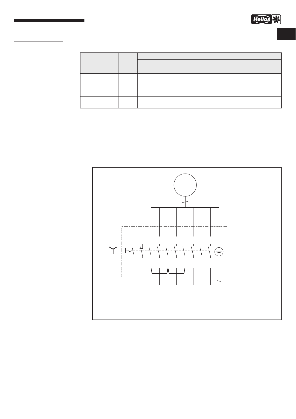
Installation and Operating Instructions
85499 022 SS-1262 18.06.19
CHAPTER 6
WIRING DIAGRAM
OVERVIEW
6.0 Wiring diagrams
B VD – Smoke exhaust roof fans F400/F600
The following table describes the fan start-up and indicates the required connection line:
Voltage specification
on motor type plate
230 / 400 V Y No Yes No
400 / 690 V
Customer-side
Connection cable
Cable Motor prot.
with TK/PTC
*Clarify direct startup with the local network operator before commissioning!
Operation
at
400 V, 3~
Y/△- startup P
△
– 6 + PE 3 + PE 3 + PE
– 2 2 2
≥
3,0 kW
M
Yes No Yes*
Single-speed
Fan start-up
Dir. startup Y P
M ≤
2,2 kW
Dir. startup △P
M ≤
EN EN
2,2 kW
SS-1262
3~ motor with RS 6+1+2 7,5
(with Y bridge)
B VD with nominal output ≤ 2,20
kW (direct startup or FU operation)
3~ Motor
M
U1
U2
1
4
1
3
5
2
4
6
V1
V2
5
7
8
9
10
W2
6
2
12 11
mit TB/TP (TK/KL)
9
W1
TB/TP
TB/TP
8
7
3
13
14
16 15
17
18
20 19
PE
RS 6+1+2 7,5
L1
L2
L3
TB/TP
TB/TP
PE
17

Installation and Operating Instructions
85499 072 SS-1307 18.06.19
85499 021 SS-1261 18.06.19
SS-1261
3~ motor with RS 6+1+2 7,5
B VD with nominal output = 3,00 kW to 7,50 kW
(star-delta startup)
B VD – Smoke exhaust roof fans F400/F600
M
9
3~ Motor
mit TB/TP (TK/KL)
SS-1307
3~ motor with RS 6+1+2 15/30/45
B VD with nominal output = 11,00
kW to 45, 00 kW (direct startup or
FU operation)
U1
U2
1
4
1
3
5
2
4
6
V1
V2
5
2
7
9
8
10
12 11
W2
6
13
14
W1
3
TB/TP
7
16 15
17
18
PE
TB/TP
8
20 19
RS 6+1+2 7,5
U2
U1
/
/
/
V1
V2
Bauseits
on site
sur site
W2
W1
TB/TP
TB/TP
PE
3~ Motor
PE
U1
M
V1
W1
1
2
3
U2
4
V2
5
mit TB/TP (TK/KL)
9
W2
6
TB/TP
7
TB/TP
8
1
3
5
1.1
1.3
2
4
6
1.2
U2
Bauseits
/
on site
/
sur site
/
1.4
V2
PE PE
V1
U1
PE
W1
18
1.5
1.6
W2
13
14
21
22
43
43
44
44
TB/TP
TB/TP
RS 6+1+2
(15 / 30 / 45)

Installation and Operating Instructions
85499 023 SS-1263 18.06.19
85499 071 SS-1306 18.06.19
SS-1263
3~ motor with RS 6+1+2 7,5
(with △ bridge)
B VD with nominal output = 3,00
kW to 7,50 kW
(direct startup or FU operation)
B VD – Smoke exhaust roof fans F400/F600
M
9
U2
4
U1
1
V2
5
V1
2
W2
6
W1
3
3~ Motor
mit TB/TP (TK/KL)
TB/TP
7
PE
TB/TP
8
EN EN
SS-1306
3~ motor with RS 6+1+2
15/30/45 (with △ bridge)
B VD with nominal output =
11,00 kW to 45,00 kW
(star-delta startup)
PE
1
3
2
4
7
5
6
9
8
10
13
12 11
14
16 15
17
18
20 19
RS 6+1+2 7,5
L1
L2
L3
TB/TP
TB/TP
PE
3~ Motor
U1
1
V1
2
W1
3
U2
4
M
V2
5
mit TB/TP (TK/KL)
9
W2
6
TB/TP
7
TB/TP
8
1
3
5
1.1
1.3
1.5
2
4
6
1.2
1.4
PE PE
L2
L3
19
L1
PE
1.6
13
14
21
22
43
43
44
44
TB/TP
TB/TP
RS 6+1+2
(15 / 30 / 45)

Installation and Operating Instructions
B VD – Smoke exhaust roof fans F400/F600
COMMISSIONING REPORTCHAPTER 7
according to DIN 31051
Please fill in the commissioning report.
The example copy will remain in this documentation. Any questions relating to the warranty can only be clarified upon presentation of the
-
commissioning report!
Installing company: ..................................................................................................................................................................................
Location/company HQ: ........................................................................ Tel. / Email:............................................................................
Installation date Remarks:
Installation designation
Series/type
Production code
Series number
Approval number
Nominal data
Nominal value Actual value Unit
Motor type
Motor number
Motor protection (e.g. KL, TK)
Motor speed [rpm]
Protection (e.g. 3-pole, A,B,C) – –
Nominal voltage [V]
Nominal current [A]
Mains frequency [Hz]
Nominal capacity [kW]
Measured quantities
Nominal value Actual value
Speed [rpm]
Air density [kg/m
Air flow temperature [°C]
Volume flow [m
3
/h]
3
]
Pressure increase [Pa]
Operating voltage [V]
Operating current L1 [A]
Operating current L2 [A]
Operating current L3 [A]
Installation height [m] a.s.l.
20

Installation and Operating Instructions
B VD – Smoke exhaust roof fans F400/F600
EN EN
Operating mode
Ventilation mode?
Smoke extraction?
Installation position checked?
Duct connection checked?
Elastic flexible connectors?
Backdraught shutter mounted?
Duct attenuator checked?
Electrical connection by specialist
Installation according to VDE?
Unhindered running of impeller checked?
Minimum air gap checked?
Power consumption measured?
(cf. with type plate)
Vibration limits checked?
Information Value
6-pole 4-pole
YES NO
Vertical
Inlet-side
Inlet-side
YES NO
YES
YES
YES
YES
YES
YES
VALUE:
VALUE:
VALUE:
Screw connections checked for tight fit?
Protection grilles checked for tight fit?
System/duct system installed professionally?
Inspection opening on casing
freely-accessible and closed?
Air-flow direction and direction of rot. checked?
Flow monitor connected?
YES
YES
YES
YES
YES
YES NO
The electrical system meets the acknowledged rules of electrical engineering!
m
The technical documents have been passed on to the operator. They have been entrusted with the safety information, the operation
and maintenance of the fans using these Installation and Operating Instructions!
__________________________________ ___________________________________
Place, Date, Signature Place, Date, Signature
Client/Owner
21
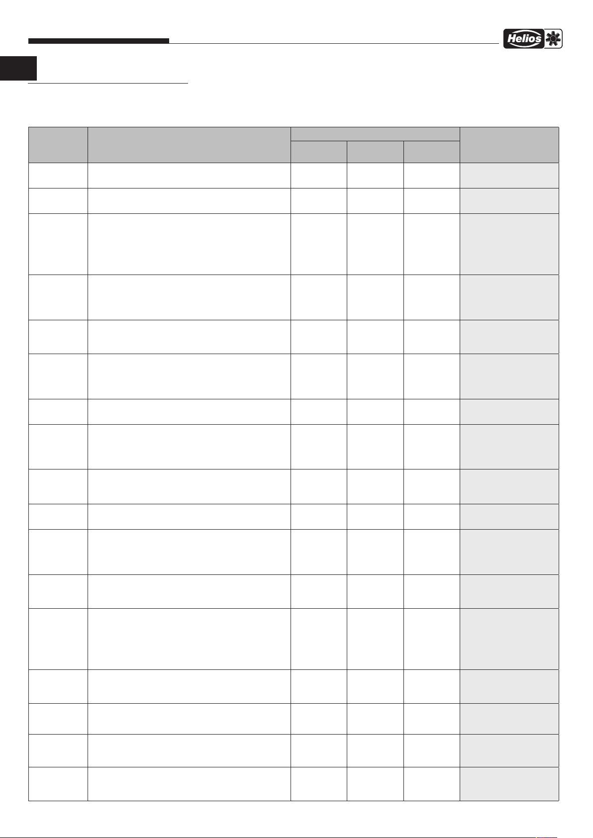
Installation and Operating Instructions
B VD – Smoke exhaust roof fans F400/F600
TEST AND MAINTENANCE PLAN
The following must be checked:
Interval Test and maintenance work Fan B VD F400/F600 To be carried out by
1/2 annual Test run up to maximum nominal speed and then deac-
tivate again.
1/2 annual Check fan and drive motor for running noises.
Standard incl. LZD
Basic
x x x
x x x
incl. LZD
Comfort
Instructed personnel
Instructed personnel
Annual Test run for at least 20 minutes and then deactivate
again.
For fans with bearing condition diagnostics, operate fan
until steady-state is reached (around 60-75 minutes)
before reading out values (see Installation and Operating
Instructions for LZD).
Annual General visual inspection and check of fan condition for
external soiling, correct fastening, corrosion and damage.
Clean components for functional integrity if needed.
Annual Check flat roof base and on-site substructure/foundation
for damage and corrosion as well as correct
fastening.
Annual Check flexible connectors and connections for tension-
free installation, tightness, correct fastening, soiling
and damage.
Clean components for functional integrity if needed.
Annual Check air gap between inlet nozzle and radial impeller.
Annual Check drive motor for soiling, corrosion, damage and
correct fastening. Clean components for functional integrity if needed.
Annual Check impeller for soiling, corrosion, damage and correct
fastening.
Clean components for functional integrity if needed.
x x x
x x x
x x x
x x x
x x x
x x x
x x x
Specialist
Specialist
Specialist
Specialist
Specialist
Specialist
Specialist
Annual Check inspection opening for tight fit, corrosion and
Annual Check protection devices (protection grilles, etc.) for soi-
Annual Check discharge grille and immediate environment for
Annual Check accessory components (deflector, hood attenua-
Annual
Annual Check intake duct for unhindered cooling air intake and
Annual Check motor protection device, for ventilation mode
Annual Check on-site bridging of frequency converter and motor
damage.
ling, corrosion, damage and correct fastening.
Clean components for functional integrity if needed.
unhindered air outlet, and remove any dirt.
tor, backdraught shutters, extension ducts, etc.) for soiling, corrosion, damage and correct fastening.
Clean components for functional integrity if needed.
Check isolator and connection cable for correct position,
damage and corrosion.
remove any dirt in the cross-section.
(motor protection device, not in case of fire).
protection devices in case of fire.
x x x
x x x
x x x
x x x
x x x
x x x
x x x
x x x
Specialist
Specialist
Specialist
Specialist
Specialist electrician
Specialist
Specialist
Specialist
22
Installation and Operating Instructions
Interval Test and maintenance work Fan B VD F400/F600 To be carried out by
Annual Measurement and evaluation of bearing conditions with
bearing condition diagnostics.
Annual Check fan vibration state.
B VD – Smoke exhaust roof fans F400/F600
Standard incl. LZD
Basic
x x x
x x x
incl. LZD
Comfort
Specialist
Specialist
EN EN
Annual Check impeller for imbalance.
5 years Replace motor bearings.
"According
to status display of LZD,
but no later
than after 10
years
No time limit,
only after warning on status
display of LZD
According
to status
See motor
type plate
Replace motor bearings.
Replace motor bearings.
Replace defective, damaged and worn parts/components on fan suspension, fan, drive motor, cooling air
fan, protection devices, attachments and accessories as
required.
Regrease motor bearings with regreasing device.
x x x
x
x
x x x
x x x
Specialist
Manufacturer or specialist
company authorised by
the manufacturer
Manufacturer or specialist
company authorised by
the manufacturer
x
Manufacturer or specialist
company authorised by
the manufacturer
Specialist
Specialist
23

Installation and Operating Instructions
DECLARATION OF PERFORMANCE
B VD – Smoke exhaust roof fans F400/F600
24

Installation and Operating Instructions
B VD – Smoke exhaust roof fans F400/F600
EN EN
25

Installation and Operating Instructions
B VD – Smoke exhaust roof fans F400/F600
26

Installation and Operating Instructions
B VD – Smoke exhaust roof fans F400/F600
EN EN
27

Installation and Operating Instructions
B VD – Smoke exhaust roof fans F400/F600
28

Installation and Operating Instructions
B VD – Smoke exhaust roof fans F400/F600
EN EN
29

Installation and Operating Instructions
B VD – Smoke exhaust roof fans F400/F600
30

Installation and Operating Instructions
B VD – Smoke exhaust roof fans F400/F600
EN EN
31

Als Referenz am Gerät griffbereit aufbewahren! Druckschrift-Nr.
Please keep this manual for reference with the unit! Print-No.:
Garder cette notice à proximité de l’unité ! N° d’impression
Service und Information
D HELIOS Ventilatoren GmbH + Co KG · Lupfenstraße 8 · 78056 VS-Schwenningen F HELIOS Ventilateurs · Le Carré des Aviateurs · 157 av. Charles Floquet · 93155 Le Blanc Mesnil Cedex
CH HELIOS Ventilatoren AG · Tannstrasse 4 · 8112 Otelfingen GB HELIOS Ventilation Systems Ltd. · 5 Crown Gate · Wyncolls Road · Severalls Industrial Park ·
A HELIOS Ventilatoren · Postfach 854 · Siemensstraße 15 · 6023 Innsbruck Colchester · Essex · CO4 9HZ
37 517-001/-/V02/0619/0719
www.heliosventilatoren.de
 Loading...