

Helios ALB, ALB 220/4/50/30 WW, ALB 280/4/60/35 WW Installation And Operating Instructions Manual

Helios Ventilatoren
MONTAGE- UND BETRIEBSVORSCHRIFT NR. 91832
Helios Außenluft-Boxen
D
ALB..
ALB-220/4/50/30 WW/EH
ALB-280/4/60/35 WW/EH

DEUTSCH
Inhaltsverzeichnis
KAPITEL 1. SICHERHEIT . . . . . . . . . . . . . . . . . . . . . . . . . . . . . . . . . . . . . . . . . . . . . . . . . . . . . . . . . . . . . . . . . . . Seite 1
1.0 Wichtige Informationen . . . . . . . . . . . . . . . . . . . . . . . . . . . . . . . . . . . . . . . . . . . . . . . . . . . . . . . . . . . . . . . . . . Seite 1
1.1 Warnhinweise . . . . . . . . . . . . . . . . . . . . . . . . . . . . . . . . . . . . . . . . . . . . . . . . . . . . . . . . . . . . . . . . . . . . . . . . . Seite 1
1.2 Sicherheitshinweise . . . . . . . . . . . . . . . . . . . . . . . . . . . . . . . . . . . . . . . . . . . . . . . . . . . . . . . . . . . . . . . . . . . . Seite 1
1.3 Einsatzbereich . . . . . . . . . . . . . . . . . . . . . . . . . . . . . . . . . . . . . . . . . . . . . . . . . . . . . . . . . . . . . . . . . . . . . . . . Seite 2
1.4 Grenzen . . . . . . . . . . . . . . . . . . . . . . . . . . . . . . . . . . . . . . . . . . . . . . . . . . . . . . . . . . . . . . . . . . . . . . . . . . . . . Seite 2
1.5 Berührungsschutz . . . . . . . . . . . . . . . . . . . . . . . . . . . . . . . . . . . . . . . . . . . . . . . . . . . . . . . . . . . . . . . . . . . . . Seite 3
1.6 Personalqualifikation . . . . . . . . . . . . . . . . . . . . . . . . . . . . . . . . . . . . . . . . . . . . . . . . . . . . . . . . . . . . . . . . . . . . Seite 3
1.7 Förder-und Drehrichtung . . . . . . . . . . . . . . . . . . . . . . . . . . . . . . . . . . . . . . . . . . . . . . . . . . . . . . . . . . . . . . . . Seite 3
1.8 Motorschutz . . . . . . . . . . . . . . . . . . . . . . . . . . . . . . . . . . . . . . . . . . . . . . . . . . . . . . . . . . . . . . . . . . . . . . . . . . Seite 3
1.9 Frostschutz . . . . . . . . . . . . . . . . . . . . . . . . . . . . . . . . . . . . . . . . . . . . . . . . . . . . . . . . . . . . . . . . . . . . . . . . . . Seite 3
1.10 Funktionssicherheit – Notbetrieb . . . . . . . . . . . . . . . . . . . . . . . . . . . . . . . . . . . . . . . . . . . . . . . . . . . . . . . . . . Seite 3
KAPITEL 2. ALLGEMEINE HINWEISE . . . . . . . . . . . . . . . . . . . . . . . . . . . . . . . . . . . . . . . . . . . . . . . . . . . . . . . . . Seite 4
2.0 Garantieansprüche – Haftungsausschluss . . . . . . . . . . . . . . . . . . . . . . . . . . . . . . . . . . . . . . . . . . . . . . . . . . . Seite 4
2.1 Vorschriften – Richtlinien . . . . . . . . . . . . . . . . . . . . . . . . . . . . . . . . . . . . . . . . . . . . . . . . . . . . . . . . . . . . . . . . Seite 4
2.2 Transport . . . . . . . . . . . . . . . . . . . . . . . . . . . . . . . . . . . . . . . . . . . . . . . . . . . . . . . . . . . . . . . . . . . . . . . . . . . . Seite 4
2.3 Sendungsannahme . . . . . . . . . . . . . . . . . . . . . . . . . . . . . . . . . . . . . . . . . . . . . . . . . . . . . . . . . . . . . . . . . . . . Seite 4
2.4 Einlagerung . . . . . . . . . . . . . . . . . . . . . . . . . . . . . . . . . . . . . . . . . . . . . . . . . . . . . . . . . . . . . . . . . . . . . . . . . . Seite 4
2.5 Leistungsdaten . . . . . . . . . . . . . . . . . . . . . . . . . . . . . . . . . . . . . . . . . . . . . . . . . . . . . . . . . . . . . . . . . . . . . . . . Seite 4
2.6 Geräuschangaben . . . . . . . . . . . . . . . . . . . . . . . . . . . . . . . . . . . . . . . . . . . . . . . . . . . . . . . . . . . . . . . . . . . . . Seite 4
KAPITEL 3. TECHNISCHE DATEN . . . . . . . . . . . . . . . . . . . . . . . . . . . . . . . . . . . . . . . . . . . . . . . . . . . . . . . . . . . . Seite 4
3.0 Technische Daten . . . . . . . . . . . . . . . . . . . . . . . . . . . . . . . . . . . . . . . . . . . . . . . . . . . . . . . . . . . . . . . . . . . . . . Seite 4
3.1 Zubehör . . . . . . . . . . . . . . . . . . . . . . . . . . . . . . . . . . . . . . . . . . . . . . . . . . . . . . . . . . . . . . . . . . . . . . . . . . . . . Seite 5
3.2 Abmessungen . . . . . . . . . . . . . . . . . . . . . . . . . . . . . . . . . . . . . . . . . . . . . . . . . . . . . . . . . . . . . . . . . . . . . . . . Seite 5
KAPITEL 4. FUNKTION / BEDIENUNG . . . . . . . . . . . . . . . . . . . . . . . . . . . . . . . . . . . . . . . . . . . . . . . . . . . . . . . . . Seite 6
4.0 Funktionsbeschreibung ALB.. . . . . . . . . . . . . . . . . . . . . . . . . . . . . . . . . . . . . . . . . . . . . . . . . . . . . . . . . . . . . . Seite 6
4.1 Einstellungen Bedienteil . . . . . . . . . . . . . . . . . . . . . . . . . . . . . . . . . . . . . . . . . . . . . . . . . . . . . . . . . . . . . . . . . Seite 6
4.2 Menüstruktur . . . . . . . . . . . . . . . . . . . . . . . . . . . . . . . . . . . . . . . . . . . . . . . . . . . . . . . . . . . . . . . . . . . . . . . . . Seite 6
4.3 Bedienoberfläche . . . . . . . . . . . . . . . . . . . . . . . . . . . . . . . . . . . . . . . . . . . . . . . . . . . . . . . . . . . . . . . . . . . . . . Seite 7
4.4 Parametereinstellungen . . . . . . . . . . . . . . . . . . . . . . . . . . . . . . . . . . . . . . . . . . . . . . . . . . . . . . . . . . . . . . . . Seite 12
KAPITEL 5. BENUTZERWARTUNG . . . . . . . . . . . . . . . . . . . . . . . . . . . . . . . . . . . . . . . . . . . . . . . . . . . . . . . . . . . Seite 13
5.0 Benutzerwartung . . . . . . . . . . . . . . . . . . . . . . . . . . . . . . . . . . . . . . . . . . . . . . . . . . . . . . . . . . . . . . . . . . . . . Seite 13
KAPITEL 6. MONTAGE UND INBETRIEBNAHME . . . . . . . . . . . . . . . . . . . . . . . . . . . . . . . . . . . . . . . . . . . . . . . Seite 13
6.0 Konstruktiver Aufbau . . . . . . . . . . . . . . . . . . . . . . . . . . . . . . . . . . . . . . . . . . . . . . . . . . . . . . . . . . . . . . . . . . Seite 13
6.1 Montage – Einbau / Abhängepunkte . . . . . . . . . . . . . . . . . . . . . . . . . . . . . . . . . . . . . . . . . . . . . . . . . . . . . . Seite 13
6.2 Elektrischer Anschluss . . . . . . . . . . . . . . . . . . . . . . . . . . . . . . . . . . . . . . . . . . . . . . . . . . . . . . . . . . . . . . . . . Seite 14
6.3 Anschluss Warmwasser-Heizregister . . . . . . . . . . . . . . . . . . . . . . . . . . . . . . . . . . . . . . . . . . . . . . . . . . . . . . Seite 15
6.4 Anschluss externer Komponenten . . . . . . . . . . . . . . . . . . . . . . . . . . . . . . . . . . . . . . . . . . . . . . . . . . . . . . . . Seite 15
6.5 Inbetriebnahme . . . . . . . . . . . . . . . . . . . . . . . . . . . . . . . . . . . . . . . . . . . . . . . . . . . . . . . . . . . . . . . . . . . . . . Seite 17
6.6 Inbetriebnahme ALB mit Warmwasser-Heizregister . . . . . . . . . . . . . . . . . . . . . . . . . . . . . . . . . . . . . . . . . . . Seite 17
6.7 Inbetriebnahme ALB mit Elektroheizung . . . . . . . . . . . . . . . . . . . . . . . . . . . . . . . . . . . . . . . . . . . . . . . . . . . . Seite 18
6.8 Betrieb . . . . . . . . . . . . . . . . . . . . . . . . . . . . . . . . . . . . . . . . . . . . . . . . . . . . . . . . . . . . . . . . . . . . . . . . . . . . . Seite 18
KAPITEL 7. INSTANDHALTUNG UND WARTUNG . . . . . . . . . . . . . . . . . . . . . . . . . . . . . . . . . . . . . . . . . . . . . . . Seite 18
7.0 Instandhaltung und Wartung . . . . . . . . . . . . . . . . . . . . . . . . . . . . . . . . . . . . . . . . . . . . . . . . . . . . . . . . . . . . Seite 18
7.1 Filterwechsel . . . . . . . . . . . . . . . . . . . . . . . . . . . . . . . . . . . . . . . . . . . . . . . . . . . . . . . . . . . . . . . . . . . . . . . . Seite 18
7.2 Reinigung . . . . . . . . . . . . . . . . . . . . . . . . . . . . . . . . . . . . . . . . . . . . . . . . . . . . . . . . . . . . . . . . . . . . . . . . . . . Seite 19
7.3 Ersatzteile . . . . . . . . . . . . . . . . . . . . . . . . . . . . . . . . . . . . . . . . . . . . . . . . . . . . . . . . . . . . . . . . . . . . . . . . . . . Seite 19
7.4 Stilllegen und Entsorgen . . . . . . . . . . . . . . . . . . . . . . . . . . . . . . . . . . . . . . . . . . . . . . . . . . . . . . . . . . . . . . . . Seite 19
7.5 Fehlerbeschreibung . . . . . . . . . . . . . . . . . . . . . . . . . . . . . . . . . . . . . . . . . . . . . . . . . . . . . . . . . . . . . . . . . . . Seite 20
KAPITEL 8. SCHALTPLÄNE . . . . . . . . . . . . . . . . . . . . . . . . . . . . . . . . . . . . . . . . . . . . . . . . . . . . . . . . . . . . . . . . . Seite 21
Erreichen der Lebensdauer, Entsorgung
Bauteile und Komponenten des Ventilators, die ihre Lebensdauer erreicht haben, z.B. durch Verschleiß, Korrosion, mechanische Belastung, Ermüdung und / oder
durch andere, nicht unmittelbar erkennbare Einwirkungen, sind nach erfolgter Demontage entsprechend den nationalen und internationalen Gesetzen und Vorschriften
fach- und sachgerecht zu entsorgen. Das Gleiche gilt auch für im Einsatz befindliche Hilfsstoffe wie Öle und Fette oder sonstige Stoffe.
Die bewusste oder unbewusste Weiterverwendung verbrauchter Bauteile wie z.B. Laufräder, Wälzlager, Keilriemen, etc. kann zu einer Gefährdung von Personen, der
Umwelt sowie von Maschinen und Anlagen führen. Die entsprechenden, vor Ort geltenden Betreibervorschriften sind zu beachten und anzuwenden.

Montage- und Betriebsvorschrift
KAPITEL 1
SICHERHEIT
1.0 Wichtige Informationen
Außenluft-Boxen
D
Zur Sicherstellung einer einwandfreien Funktion und zur eigenen Sicherheit sind alle nachstehenden Vorschriften genau
durchzulesen und zu beachten. Dieses Dokument ist Teil des Produktes und als solches zugänglich und dauerhaft aufzubewahren. Der Betreiber ist für die Einhaltung aller anlagenbezogenen Sicherheitsvorschriften verantwortlich.
GEFAHR
WARNUNG
VORSICHT
1.1 Warnhinweise
Untenstehende Symbole sind sicherheitstechnische Warnhinweise. Zur
Vermeidung von Verletzungsrisiken und Gefahrensituationen, müssen alle
Sicherheitsvorschriften bzw. Symbole in diesem Dokument unbedingt beachtet werden!
1.2 Sicherheitshinweise
Für Einsatz, Anschluss und Betrieb gelten besondere Bestimmungen; bei
Zweifel ist Rückfrage erforderlich. Weitere Informationen sind den einschlägigen
Normen und Gesetzestexten zu entnehmen.
Schutzbrille
l
Dient zum Schutz vor Augenverletzungen.
Gehörschutz
p
Dient zum Schutz vor allen Arten von Lärm.
Arbeitschutzkleidung
r
Dient vorwiegend zum Schutz vor Erfassen durch bewegliche Teile.
Keine Ringe, Ketten oder sonstigen Schmuck tragen.
Schutzhandschuhe
n
Schutzhandschuhe dienen zum Schutz der Hände vor Reibung, Abschürfungen, Einstichen oder tieferen Verletzungen, sowie vor Berührung mit heißen
Oberflächen.
Sicherheitsschuhe
m
Sicherheitsschuhe dienen zum Schutz vor schweren herabfallenden Teilen
und verhindern Ausrutschen auf rutschigem Untergrund.
Haarnetz
Das Haarnetz dient vorwiegend zum Schutz vor Erfassen von langen Haaren
durch bewegliche Teile.
Bei allen Arbeiten am Ventilator sind die allgemein gültigen
Arbeitsschutz- und Unfallverhütungsvorschriften einzuhalten!
• Alle elektrischen Arbeiten, die Inbetriebnahme, Installations-, Instand haltungsund Wartungsarbeiten dürfen nur von autorisiertem Elektrofachpersonal
durchgeführt werden!
• Ein allpoliger Netztrennschalter / Revisionsschalter mit mindestens 3 mm
Kontakt öffnung (EN 60335-1) ist bei Typen ..WW montiert. Für Typen ..EH ist
ein zusätzlicher Revisionsschalter vor der Elektroheizung vorzusehen.
• Vor allen Reinigungs-, Installations-, Instandhaltungs- und Wartungsarbeiten
oder vor Öffnen des Anschlussraums ist folgendes einzuhalten:
– Das Gerät ist allpolig vom Netz zu trennen!
– Der Stillstand rotierender Teile ist abzuwarten!
– Das Gerät ist gegen Wiedereinschalten zu sichern!
1

Montage- und Betriebsvorschrift
D
Außenluft-Boxen
• Gerätedeckel nicht öffnen, wenn das Gerät in Betrieb ist!
• Gerät bis zum Einbau nur verpackt bewegen!
• Gerät nur mit für das Gewicht geeigneten Transportmitteln bewegen, beim
Transport Sicherheitsschuhe tragen!
• Beim Auspacken des Geräts Handschuhe/Sicherheitsschuhe tragen.
• Geeignete Tragkraft, -eigenschaften des Befestigungsuntergrunds sicherstellen und diesbezüglich geeignete Befestigungsmittel verwenden.
• Der Betreiber ist für die Einhaltung aller anlagenbezogenen Sicherheits vorschriften verantwortlich!
• Anormal häufiges Ein-/Ausschalten ist nicht zulässig.
• Der Berührungsschutz für das Laufrad gemäß DIN EN 13857 ist sicherzustellen.
• Der Planer und Betreiber muss eine leichte Zugänglichkeit für Inspektionsund Reinigungsarbeiten gewährleisten!
• Eine gleichmäßige Zuströmung und ein freier Ausblas sind zu gewährleisten.
• Bei Betrieb von schornsteinabhängigen Feuerstellen im entlüfteten Raum muss
bei allen Betriebsbedingungen für ausreichend Zuluft gesorgt werden
(Rückfrage beim Schornsteinfeger).
Frostschutzhinweise
ALB Außenluft-Boxen Type ..WW beinhalten ein Warmwasser-Heizregister.
Damit Frostschäden vermieden werden, muss immer Heizungswasser verfügbar
sein. Die Heizanlage muss immer in Betrieb sein, auch wenn die
Lüftungsanlage ausgeschaltet ist oder sich im Nachtmodus befindet. Um
sicherzustellen, dass keine kalte Außenluft unter +5°C an den Wärmetauscher
gelangt, muss immer eine Außenverschlussklappe im Lüftungssystem
integriert sein.
1.3 Einsatzbereich
– Bestimmungsgemäßer Einsatz:
Speziell für direktes Zwischensetzen in Lüftungs-Kanal-/Rohrsysteme konzipiert und für vielseitige Anwendungen im
Gewerbebereich. Die Geräte sind für den Einsatz in trockener Innenumgebung im Temperaturbereich von +5 °C bis
+35 °C vorgesehen. Sie eignen sich für den Transport von reiner Luft ohne Staub, Fett, chemischer Verdunstung und
anderen Verunreinigungen.
- Max. relative Luftfeuchtigkeit: 80%
- Elektrische Schutzart: IP 20
Die Geräte sind nur für die Aufstellung in frostfreien Räumen konzipiert. Bei Außenaufstellung können Frost – und
Wasserschäden entstehen.
– Vernünftigerweise vorhersehbarer Fehlgebrauch:
Die ALB sind nicht zum Betrieb unter erschwerten Bedingungen wie z.B. hohe Feuchtigkeit, aggressive Medien, starke
Verschmutzung, übermäßige Beanspruchung durch klimatische, technische oder elektronische Einflüsse geeignet. Eine
Verwendung in einer mobilen Einheit (z.B. Fahrzeuge, Flugzeuge, Schiffe, usw.) ist nicht vorgesehen.
– Missbräuchlicher, untersagter Einsatz:
Aufstellung im Freien oder im direkten Kontakt mit Wasser. Förderung von explosionsfähigen Gasgemischen/Medien.
Aufstellung in einem/r explosionsgefährdeten Bereich/Atmosphäre. Betrieb ohne normgerechte Schutzeinrichtungen
(z.B. Schutzgitter). Förderung von Feststoffen oder Flüssigkeiten. Förderung von abrasiven und/oder die
Gerätewerkstoffe angreifende Medien. Förderung von fetthaltigen Fördermedien.
1.4 Grenzen
Räumlich:
Vor und hinter der ALB ist eine gerade glatte Rohrstrecke von 500 mm vorzusehen. Bei Verwendung am Anfang einer
Rohrleitung sind die Lufteintrittsöffnungen mit einer Klappe (WSG, Zubehör) zu versehen. Bei Verwendung am Ende
einer Rohrleitung ist ausblasseitig ein Schutzgitter vorzusehen.
Ausblasseitiges Umfeld muss für unbefugte Personen unzugänglich sein und darf nicht versperrt werden.
Der Ventilator muss für Reinigungs- und Wartungszwecke leicht zugänglich sein, insbesondere der Klemmenkasten.
Schnittstelle Energieversorgung:
- Anschluss nur mit festverlegten Leitungen laut Anschlussplan
2

Montage- und Betriebsvorschrift
1.5 Berührungsschutz
1.6 Personalqualifikation
1.7 Förder- und Drehrichtung
Außenluft-Boxen
D
Beim Einbau sind die allgemein gültigen Arbeitsschutz- und Unfallverhütungsvorschriften einzuhalten!
Der Betreiber ist für die Einhaltung verantwortlich!
– Kontakt mit rotierenden Teilen muss verhindert werden.
– In Abhängigkeit der Einbauverhältnisse kann ein Berührungsschutz erforderlich sein. Entsprechende Schutzgitter sind
vorzusehen.
– Ventilatoren, die durch ihre Einbauweise (z.B. Einbau in Lüftungskanäle oder geschlossene Aggregate) geschützt sind,
benötigen kein Schutzgitter, wenn die Anlage die gleiche Sicherheit bietet. Es wird darauf hingewiesen, dass der
Betreiber für Nichteinhaltung der aktuellen Norm (DIN EN 13857) und für Unfälle infolge fehlender Schutzeinrichtungen
haftbar gemacht werden kann.
– Alle elektrischen Arbeiten, die Inbetriebnahme, Installation, Wartung und Instandhaltung dürfen nur von Elektro -
fachkräften ausgeführt werden
– ALB können von Kindern ab 8 Jahren und darüber sowie von Personen mit verringerten physischen, sensorischen
oder mentalen Fähigkeiten oder Mangel an Erfahrung und Wissen benutzt werden, wenn sie beaufsichtigt oder bezüglich des sicheren Gebrauchs des Gerätes unterwiesen wurden und die daraus resultierenden Gefahren verstehen.
Kinder dürfen nicht mit dem Gerät spielen. Reinigung und Benutzer-Wartung darf nicht von Kindern ohne
Beaufsichtigung durchgeführt werden.
WARNUNG
WARNUNG
ACHTUNG
WARNUNG
Durch vom Ventilator herausgeschleuderte Teile können Ihre Augen verletzt werden!
Zur Drehrichtungskontrolle Schutzbrille tragen!
WARNUNG
Das drehende Laufrad kann Ihre Finger/Arme abtrennen oder einziehen!
Betrieb nur mit montierten Sicherheitseinrichtungen!
Beschädigungsgefahr!
Keine Gegenstände in das rotierende Laufrad stecken.
Drehrichtung und Luftförderrichtung müssen mit den am Gerät angebrachten Pfeilen übereinstimmen.
Drehrichtung darf nur nach Abschalten bzw. Austrudeln des Ventilators geprüft werden.
Falsche Drehrichtung kann zur Überhitzung des Motors führen!
1.8 Motorschutz
– 1-Phasen Motoren
Alle 1-Phasen Motoren sind mit Thermokontakten ausgestattet, die mit der Wicklung in Reihe verschaltet sind und
selbsttätig aus- und nach erfolgter Abkühlung wiedereinschalten.
– 3-Phasen Motoren
Alle 3-Phasen Motoren sind mit Thermokontakten ausgestattet, die von der Gerätesteuerung überwacht werden. Bei
Ansprechen der Thermokontakte schaltet die Steuerung den Motor aus.
1.9 Frostschutz
Die Außenluftboxen ALB 220/4/50/30.. und ALB 280/4/60/35.. sind mit einer Frostschutzeinrichtung ausgestattet.
Damit diese wirksam ist, müssen folgende wichtigen Punkte erfüllt sein:
- Geräte dürfen nur in Innenräumen aufgestellt werden.
- minimale Umgebungstemperatur +5 °C.
- ALB darf nie ausgeschaltet bzw. stromlos geschaltet werden.
- Die Heizungsanlage muss immer in Betrieb sein.
- Die Vorlauftemperatur muss überprüft werden.
- Für Typen ..WW muss eine ausreichende Warmwasserzufuhr sichergestellt sein.
- Eine dichte Außenluftklappe (elektrisch) ist zwingend erforderlich.
- Eine regelmäßige Wartung und Funktionsprüfung muss durchgeführt werden.
- Wird das Gerät außer Betrieb gesetzt, muss das Warmwasser-Heizregister entleert werden.
- Bei Betrieb mit zusätzlichem Abluft-Ventilator muss sichergestellt sein, dass im Störfall die Klappe schließt.
- Bei Funktionsstörungen, Wartungsarbeiten, Fehlersuche usw., ist bei niedrigen Außentemperaturen das
Warmwasser-Heizregister zu entleeren.
1.10 Funktionssicherheit – Notbetrieb
Bei Einsatz des Geräts in wichtiger versorgungstechnischer Funktion ist die Anlage so zu konzipieren, dass bei
Geräteausfall automatisch ein Notbetrieb garantiert ist. Geeignete Lösungen sind z.B.: Parallelbetrieb von zwei
leistungsschwächeren Geräten mit getrenntem Stromkreis, Standby-Gerät, Alarmeinrichtungen und
Notlüftungssysteme.
3

Montage- und Betriebsvorschrift
D
KAPITEL 2
ALLGEMEINE HINWEISE
Außenluft-Boxen
2.0 Garantieansprüche – Haftungsausschluss
Alle Ausführungen dieser Dokumentation müssen beachtet werden, sonst entfällt die Gewährleistung. Gleiches gilt für
Haftungsansprüche an Helios. Der Gebrauch von Zubehörteilen, die nicht von Helios empfohlen oder angeboten
werden, ist nicht statthaft. Eventuell auftretende Schäden unterliegen nicht der Gewährleistung. Veränderungen und
Umbauten am Gerät sind nicht zulässig und führen zum Verlust der Konformität, jegliche Gewährleistung und Haftung
ist in diesem Fall ausgeschlossen.
2.1 Vorschriften – Richtlinien
Bei ordnungsgemäßer Installation und bestimmungsgemäßem Betrieb entspricht das Gerät den zum Zeitpunkt seiner
Herstellung gültigen Vorschriften und EU-Richtlinien.
2.2 Transport
Die ALB ist werkseitig so verpackt, dass sie gegen normale Transportbelastungen geschützt ist. Der Transport ist
sorgfältig durchzuführen. Es wird empfohlen, den Ventilator in der Originalverpackung zu belassen. Zum Transport oder
zur Montage muss die ALB am Gehäuse oder den vorgesehenen Trageösen aufgenommen werden. Hierbei geeignetes
Hebezeug und Befestigungsvorrichtungen verwenden. Gewichtsangaben sind der Kennzeichnung am Gerät zu
entnehmen.
ACHTUNG
ACHTUNG
Ventilator nicht an Anschlussleitungen, Klemmenkasten oder Laufrad transportieren!
Nicht unter der schwebenden Last aufhalten!
2.3 Sendungsannahme
Die Sendung ist sofort bei Anlieferung auf Beschädigungen und Typenrichtigkeit zu prüfen. Falls Schäden vorliegen,
umgehend Schadensmeldung unter Hinzuziehung des Transportunternehmens veranlassen. Bei nicht fristgerechter
Reklamation gehen evtl. Ansprüche verloren.
2.4 Einlagerung
Bei Einlagerung über längeren Zeitraum sind zur Verhinderung schädlicher Einwirkungen folgende Maßnahmen zu
treffen: Schutz des Geräts durch trockene, luft- und staubdichte Verpackung (Kunststoffbeutel mit Trockenmittel und
Feuchtigkeitsindikatoren). Der Lagerort muss erschütterungsfrei, wassergeschützt und frei von Temperaturschwankungen
sein. Lagertemperatur -20 °C bis +40 °C, diese Grenzwerte dürfen nicht überschritten werden.
Bei Lagerung unter 0 °C muss das Gerät vor Inbetriebnahme min. 2 h unter Betriebsbedingungen im
Ruhezustand belassen werden, damit im Inneren ein Temperaturausgleich stattfinden kann.
Bei mehrjähriger Lagerung bzw. Motorstillstand muss vor Inbetriebnahme eine Inspektion der Lager und gegebenenfalls
ein Lageraustausch durchgeführt werden. Bei Weiterversand (vor allem über längere Distanzen; z.B. Seeweg) ist zu
prüfen, ob die Verpackung für Transportart und -weg geeignet ist. Schäden, deren Ursache in unsachgemäßem
Transport, Einlagerung oder Inbetriebnahme liegen, sind nachweisbar und unterliegen nicht der Gewährleistung.
2.5 Leistungsdaten
Das Typenschild gibt über die elektrischen Werte Aufschluss; diese müssen mit dem örtlichen Versorgungsnetz
abgestimmt sein. Die Ventilatorleistungen* wurden auf einem Prüfstand entsprechend DIN EN ISO 5801:2010-12
ermittelt; sie gelten für die Nenndrehzahl und Normalausführung ohne Schutzgitter bei ungehinderter An- und
Abströmung und einem saug- und druckseitigen Kanal mit Länge 2,5x lange Kanalseite. Hiervon abweichende
Ausführungen und ungünstige Einbau- und Betriebsbedingungen können zu einer Reduzierung der Förderleistung
führen.
KAPITEL 3
TECHNISCHE DATEN
* (Leistungs- u. Geräuschangaben aus den
aktuell gültigen Helios Druckschriften und
dem Internet)
2.6 Geräuschangaben
Die Geräuschangaben* beziehen sich ebenfalls auf die vorstehend beschriebene Anordnung. Verschiedene
Einflussfaktoren wie ungünstige Betriebsbedingunen, etc. können zu einer Erhöhung der angegebenen Katalog-Werte
führen. Angaben, die sich auf bestimmte Abstände (1, 2, 4 m) beziehen, gelten für Freifeldbedingungen. Der
Schalldruckpegel kann im Einbaufall erheblich von der Katalogangabe abweichen, da er stark von den
Einbaugegebenheiten, d.h. vom Absorptionsvermögen des Raumes, der Raumgröße u.a. Faktoren abhängig ist.
3.0 Technische Daten
ALB 220/4/50/30 WW ALB 280/4/60/35 WW
Spannung, Frequenz 230 V, 50 Hz, 1~ 400 V, 50 Hz, 3 ~
Nennstrom max. [A] 6,1 2,75
Schutzart IP 20 IP 20
Drehzahl max. [1/min] 1460 1450
Förderleistung freiblasend [m³/h] 3200 4700
Umgebungstemperatur min/max [°C] + 5/+ 35 + 5/+ 35
Temperaturklasse 155 155
Gewicht ca. kg 80 110
4

Montage- und Betriebsvorschrift
3.1 Zubehör
Außenluft-Boxen
ALB 220/4/50/30 WW / Best. Nr. ALB 280/4/60/35 WW / Best. Nr.
Ersatz- und Pollenfilter ELF-ALB 220/4/50/30 G4 / 3646
ELF-ALB 220/4/50/30 M5 / 3647
ELF-ALB 220/4/50/30 F7 / 3648
Hydraulikeinheit WHSH EH 24 V (0-10V) / 8318
Druckdifferenz-Schalter DDS / 0445
Übergangsstück Symmetrisch ALB-ÜS 220/4/50/30 / 7515 ALB-ÜS 280/4/60/35 / 7516
Flexible Verbindungsmanschette FM 315 / 1674 FM 355 / 1675
Winkel-Flanschring FR 315 / 1204 FR 355 / 1205
Verbindungskabel (extra lang) ALB-SK 30 / 2517 – 30 Meter lang
ALB-SK 50 / 2518 – 50 Meter lang
CO
-/Feuchtefühler KWL-CO2/ 4272
2
Abluftsteuerung inkl. Kanal-Temperaturfühler
und Verbindungskabel (10 m)
Anschlussleitungsabzweig
(max. Leitungslänge 50 m)
Weiteres Zubehör ist dem aktuellen Katalog zu entnehmen.
ALB-ASW 220/4/50/40 / 3655 ALB-ASD 280/4/60/35 / 3656
KWL-FTF / 4273
KWL-ALA / 9960
ELF-ALB 280/4/60/35 G4 / 3649
ELF-ALB 280/4/60/35 M5 / 3650
ELF-ALB 280/4/60/35 F7 / 3654
D
3.2 Abmessungen
ALB 220/4/50/30..
Alle Maße in mm
ALB 280/4/60/35..
Alle Maße in mm
5

n
o
M
D
A
K
N
U
F
tag
P
K
e-
TEL
I
ON
I
T
4
N
U
N
E
I
D
BE
/
4.0
G
.1
4
tbi
tar
S
Gerät einschalten
Touch-Screen antippen
u
F
Di
ge
und
i
E
l
e
n
ds
u
A
s
n
o
kti
n
nl
uße
A
und
t
r
e
t
l
i
f
ge
or
v
n
u
l
tel
s
m
r
i
ch
ß
bes
uf
wä
g
e
a
en
t
f
lu
n
rei
ch
xe
o
B
-
t
e
i
d
uf
Fr
e
t
m
r
edi
B
☛
= anwählbares Element
☛
r
ktu
u
tr
s
ü
Men
4.2
-B
bu
n A
v
i
en
n
e
ox
..
B
L
A
g
n
.. v
LB
ge
ge
or
t
uf
hl
sc
l
tei
on H
b
b
os sor
i
l
e
e
p
m
e
T
ne
e
nöt
e
d
r
i
w
gt
i
➀
ge
t
a
r
. Ob
➃➅
e
ür
n f
wä
r
e
ur
B
m
i
i
n a
m
r
st
i
t
r
nge
wi
o, d
ne
. A
d
r
r
e
B
hm
LB
out
a
s R
e
nd
si
ue
q
i
➆
➁
➧
➂
➄
➇
d
a
m
i
l
k
um
a
ür
f
l
a
e
d
i
nd
a
r
e
od
➀ Hauptmenü
➁ Uhrzeit
➂ Power-Off
➃ Zeitschaltuhr aktiv
➄ Warnsymbol/Fehleranzeige
➅ Nachtmodus aktiv
➆ Position/Temp. Steuersensor
➇ Ventilatorstufe (1-5 bzw. Auto.-Modus)
ühr
uf
h Z
c
ur
um
ä
R
e
l
l
w
n Ge
e
r
e
e
e
ung e
ge
b
r
xt
ne
g
i
e
e
r
e
b
e
uße
A
r
rne
e
, i
t
c
i
he
n d
n sa
ne
e
n.
e
i
, d
t
uf
nl
e
r
e
ub
t
f
ri
ch
rs
o
v
s
eb
etri
B
d
n
u
6

M
4.3 Bedienoberfläche
Einstellen der Sollwerttemperatur
Einstellung der Sollwerttemperatur im Bereich von 5-30°C in 1°C Schritten.
➁
☛
Einstellen der Ventilatorstufe
Einstellung der Ventilatorstufe 1-5
➧
➧
➂
➁
u
A
t
f
lu
n
e
ß
-B
n
e
ox
➀ Solltemperatur einstellen
➁ Position/Temp. Fühler*
➂ Bestätigung u. zurück
➀
➀ Ventilatorstufe einstellen
➁ Bestätigung u. zurück
➀
t
f
ri
ch
rs
o
v
s
eb
etri
B
d
n
u
e-
tag
n
o
☛
Bei aktiviertem Automatikmodus (siehe Konfigurationsmenü
„Gerätemodus”), wird dies durch ein eingeblendetes „A” im
Startbildschirm signalisiert. Nach Auswahl einer manuellen
Ventilatorstufe im Startbildschirm kehrt das Gerät nach 30 min.
☛
Nachtmodus aktiv
Aktivierung/Deaktivierung im Konfigurationsmenü. Aktiver Nachtmodus kann durch Betätigung des
Ventilatorsymbols vorzeitig beendet werden (bis zum nächsten Schaltzyklus).
zurück in den Automatikmodus.
➀ Nachtmodus vorzeitig beenden
➁ Bestätigung u. zurück
D
*Anzeige aktueller Fühler
Fühler im Bedienteil
Fühler Zuluft
Fühler Abluft
Einstellung Fühlerposition:
Konfigurationsmenü
➧
☛
Fehlertaste
Bei eingeblendetem Warnsymbol kann durch Antippen zur Fehleranzeige gewechselt werden.
➁➀
Fehlerbeschreibung:
siehe Kapitel 4.4
➧
☛
Anzeige Filterwechsel
Bei eingeblendetem Filterwechselsymbol muss der Luftfilter getauscht werden. Anschließend muss der
Betriebsstundenzähler durch Antippen des Symbols zurückgesetzt werden. Für den Filterwechsel beim
Abluftgerät wird im Filterwechselsymbol ein „ S” eingeblendet.
➀ Reset nach Filterwechsel
➁ Bestätigung u. zurück
➧
➁➀
☛
Falls in der Reinigungseinstellung im Konfigurationsmenü „ Druck” ausgewählt und ein DDS Drucksensor
installiert wurde, erlischt das Symbol nach erfolgtem Filterwechsel automatisch.
Hauptmenü
☛
➀➂
➧
➅➁➆➄
➃
➀ Zeitschaltuhr
➁ Uhrzeit/Tag
➂ Sprache
➃ Solltemperatur
➄ Zurück
➇
➅ Helligkeit
➆ Konfigurationsmenü
➇ Ventilatorstufe
7

Montage- und Betriebsvorschrift
Außenluft-Boxen
D
Zeitschaltuhr
➂
☛
Hauptmenü
> Zeitschaltuhr: Wochenmodus
Für jeden Wochentag lassen sich vier individuelle Einschaltzeiten einstellen.
☛
Menü Zeitschaltuhr
> Zeitschaltuhr: Tagmodus
Es lassen sich insgesamt vier individuelle Einschaltzeiten einstellen.
☛
enü Zeitschaltuhr
M
➧
➧
➧
➀
➁
➁
➀
➀
➃
➁
➃
➃
➄
➂
➄
➂
➀ Zeiten anzeigen
➁ Bestätigung u. zurück
➂ Zeitschaltuhr ein/aus
➃ Tag-/Wochenmodus
➄ Zeitschaltuhr einstellen
➀ Bestätigung u. zurück
➁ Einschaltzeit
➂ Ausschaltzeit
➃ Zeit Nr.
➄ Tag vor/zurück
➀ Bestätigung u. zurück
➁ Einschaltzeit
➂ Ausschaltzeit
➃ Zeit Nr.
> Zeitschaltuhr: Übersicht
☛
Menü Zeitschaltuhr
Uhrzeit / Tag
☛
Hauptmenü
Menüsprache
☛
Hauptmenü
Helligkeit
☛
Hauptmenü
➧
➧
➧
➧
➁
➀
➁
➀
➀
➂➃
➀
➂
➃
➁
➃
➀ Bestätigung u. zurück
➁ Einschaltzeit
➂ Ausschaltzeit
➃ Tag vor/zurück
➀ Zurück
➁ Bestätigung
➂ Auswahl Tag
➃ Uhrzeit
➀ Bestätigung u. zurück
➁ Auswahl Sprache
➀ Bestätigung u. zurück
➁ Anpassung Helligkeit Gerät an
➁
➂ Anpassung Helligkeit Gerät aus
➂
➃ Tastenton ein/aus
Konfigurationsmenü
Hauptmenü
☛
➧
➀ PIN löschen
➀
➧
➀➁➂
➁
➁ Eingabe PIN: 1616
➂ Bestätigung
➃ Zurück
➂➃
➀ Zurück
➁ Auswahl treffen
➂ Bestätigung der Auswahl
8

Montage- und Betriebsvorschrift
> Konfigurationsmenü: Gerätemodus
☛
➧
➀
onfigurationsmenü
K
➧
➧
Gerätemodus
☛
Außenluft-Boxen
➁
➀
➀ Bestätigung u. zurück
➂
➁ Intervall f. Temperaturänderungen
➂ Modus manuell/auto
➃
➃ Funktion nicht aktiv (typenabhängig)
➄
➄ Offseteinstellung der
Zu-/Abluftgeräte
➀ Bestätigung u. zurück
➁ Wert erhöhen/verringern*
➁
D
* Beispiel: Wird „-2” gewählt, ist die Dreh-
zahl des Ventilators des Abluftgerätes um
zwei Stufen geringer als die des Zuluftgerätes. Wird beim Zuluftgerät Stufe 1
oder 2 gewählt, läuft der Ventilator des
Abluftgerätes in Stufe 1.
➀ Bestätigung u. zurück
➁ Nicht aktiv
☛
Gerätemodus
☛
Gerätemodus
> Konfigurationsmenü: Nachtmodus
Der Nachtmodus ist nur in Verbindung mit der Zeitschaltuhr wirksam. Wenn der Nachtmodus eingeschaltet ist, wechselt das Gerät bei Erreichen einer Ausschaltzeit der Zeitschaltuhr in den Nachtmodus und hält
die hier eingestellte Temperatur und Lüftungsstufe, bis die nächste Einschaltzeit der Zeitschaltuhr erreicht
ist. Während der Nachtmodus läuft, kann er vom Benutzer im Startbildschirm beendet werden. Das Gerät
geht dann erst nach Erreichen der nächsten Ausschaltzeit der Zeitschaltuhr wieder in den Nachtmodus.
☛
Konfigurationsmenü
> Konfigurationsmenü: Panelschloss
Die PIN-Zahl wird bei jeder Einstellungsänderung abgefragt!
☛
Konfigurationsmenü
➧
➧
➧
➧
➀
➁
Manuell: Lüftungsgerät hält die eingestellte Drehzahl/Temperatur.
Auto: Drehzahl richtet sich nach CO2-Konzentration bzw.
relativer Luftfeuchtigkeit.
➂
➁
➀
➀
➂ Wert erhöhen/verringern**
➂
➀ Bestätigung u. zurück
➁ Lüftungsstufe im Nachtmodus
➂ Nachtmodus ein/aus
➃
➃ Temperatur im Nachtmodus
➀ Bestätigung u. zurück
➁
➁ PIN einstellen
➂ PIN aktivieren/deaktivieren
➂
** Intervalleinstellung für Temperaturänder-
ungen. In den eingestellten Intervallen ändert das Lüftungsgerät die geforderte
Temperatur im Bereich von ±1°C.
> Konfigurationsmenü: Startmodus
Nach dem Einschalten läuft das Gerät für die eingestellte Zeit mit der definierten Drehzahl.
➀ Bestätigung u. zurück
➃
➁
➀
➧
☛
Konfigurationsmenü
> Konfigurationsmenü: Kanaltemperatur
Einstellung der maximalen und minimalen Temperatur der zugeführten Luft.
☛
Konfigurationsmenü
➧
➀
➂
➁ Startmodus an/aus
➂ Drehzahl einstellen
➃ Dauer einstellen
➀ Bestätigung u. zurück
➁ Temperatur einstellen
➁
9

Montage- und Betriebsvorschrift
Außenluft-Boxen
D
> Konfigurationsmenü: PID Konst.
Einstellung der Regelungskurve, nur nach Rücksprache mit dem Hersteller zu tätigen (Kapitel 4.4).
☛
onfigurationsmenü
K
> Konfigurationsmenü: Temperaturfühler
Die Soll-Temperatur wird am gewählten Fühler erreicht und gehalten.
☛
Konfigurationsmenü
> Konfigurationsmenü: CO2-Konzentration
Einstellung für die Abhängigkeit der Drehzahl von der CO2-Konzentration (bei installiertem und aktiviertem
Fühler). Nach Überschreitung der eingestellten Werte schaltet das Gerät auf eine höhere Drehzahl. Sinkt
die CO2-Konzentration, wird auf eine niedrigere Stufe umgeschaltet. Bei der „Benutzer spezi fischen
Einstellung“ werden die Grenzbereiche der einzelnen Drehzahlstufen automatisch anhand der Historie der
Eingriffe des Benutzers in die Automatik angepaßt.
Beispiel: Der Grenzwert 600 ppm ist für die 3. Stufe der Drehzahl eingestellt. Die Regelung hat aber registriert, dass bei dieser CO2-Konzentration der Benutzer die Drehzahl manuell erhöht hat. Nach der
Betätigung der Taste „Benutzerspezifische Einstellung“ wird automatisch der Grenzwert der Konzentration
für die 4. Stufe der Drehzahl auf 600 ppm verändert.
Die Einstellung der CO2-Konzentration für die 1.Stufe der Drehzahl hat keine Bedeutung. Wenn die CO2Konzentration nicht unter den eingestellten Wert fällt, wird das Lüftungsgerät nicht ausgeschaltet, sondern
läuft auf der 1. Drehzahlstufe weiter.
☛
Konfigurationsmenü
➧
➧
➧
➁
➂
➃
➀
➁
➀
➀ Bestätigung u. zurück
➁ Fühler Bedienteil
➂ Fühler Kanal
➃ Fühler Abluft
➀ Bestätigung u. zurück
➁ Werte definieren
➂ Benutzerspezifische Einstellung
➂
> Konfigurationsmenü: RH-Konzentration (relative Luftfeuchtigkeit)
Einstellung der Abhängigkeit der Drehzahl von der rel. Luftfeuchtigkeit (bei installiertem und aktiviertem
Fühler). Die rel. Luftfeuchtigkeit wird in % angegeben. Bei einer Überschreitung der eingestellten Werte
schaltet das Lüftungsgerät auf eine höhere Drehzahl. Sinken die Werte, wird auf eine niedrigere Drehzahl
umgeschaltet. Bei der „Benutzer spezi fischen Einstellung“ werden die Grenzbereiche der einzelnen
Drehzahlstufen automatisch anhand der Historie der Eingriffe des Benutzers in die Automatik angepaßt
(siehe obiges Beispiel analog). Die Einstellung der rel. Luftfeuchtigkeit für die 1. Stufe der Drehzahl hat keine Bedeutung. Wenn die rel. Luftfeuchtigkeit nicht unter den eingestellten Wert fällt, wird das
Lüftungsgerät nicht ausgeschaltet, sondert läuft auf der 1. Drehzahlstufe weiter.
➀ Bestätigung u. zurück
☛
➁
➧
Konfigurationsmenü
> Konfigurationsmenü: Luftqualitätsfühler (angeschlossene Fühler)
Angeschlossene Fühler müssen für die korrekte Funktion der Regelung nach Typ (CO2/ Luftfeuchte RH)
und Ort des Anschlusses (an ALB Hauptgerät / an Abluftgerät) markiert werden.
☛
Konfigurationsmenü
Falls der Haken in der Zeile „ Kein“ gesetzt ist, wird die Regelung den angeschlossenen Fühler ignorieren.
Damit die Regelung der Ventilatorstufe nach den Luftqualitätsfühlern erfolgt, muss im Menü Gerätemodus
der automatische Modus ausgewählt werden. Bei zwei angeschlossenen Fühlern erfolgt die Regelung der
Ventilatorstufe nach dem Fühler, der die höhere Ventilatorstufe auslöst. Im manuellen Modus wird die vom
Benutzer eingestellte Drehzahl konstant gehalten.
➧
➀
➁➂➀
➁ Werte definieren
➂ Benutzerspezifische Einstellung
➂
➀ Bestätigung u. zurück
➁ Fühler ALB
➂ Fühler Abluftgerät
10

Montage- und Betriebsvorschrift
> Konfigurationsmenü: Reinigungseinstellungen
☛
onfigurationsmenü
K
Bei Filterreinigung in Abhängigkeit der Betriebsstunden wird nach 720 Betriebsstunden mit voller
Ventilatorleistung die Aufforderung zur Filterreinigung (oder Filterwechsel) angezeigt. Bei niedrigeren
Drehzahlen wird die Stundenanzahl entsprechend reduziert. Bei Filterreinigung in Abhängigkeit des
Druckverlustes muss ein Differenzdrucksensor DDS als Öffner verdrahtet werden.
> Konfigurationsmenü: Test Heizung/Ventilator
Manueller Funktionstest der Heizung und des Ventilators. Der Testmodus ist unabhängig von den übrigen
Einstellungen.
➧
➧
☛
onfigurationsmenü
K
> Konfigurationsmenü: Ext. Schalter
☛
Konfigurationsmenü
> Konfigurationsmenü: Werkseinstellungen
➧
Außenluft-Boxen
➂
➃
➁
➀
➁
➀
➁
➀
➀ Bestätigung u. zurück
➁ Filterreinigung in Abhängigkeit der
Betriebsstunden
➂ Filterreinigung in Abhängigkeit des
Druckverlustes
➂
➂
➀ Bestätigung u. zurück
➁ Heizung 10-100 %, 10%-Schritte.
Heizung wird periodisch einund ausgeschalten.
➂ Ventilator, Stufe 1-5
➀ Bestätigung u. zurück
➁ Ext. Schalter. Gerät schaltet bei
geschlossenem Schalter aus.
➂ Brandkontakt. Gerät wird im Notfall
mit geöffnetem/unterbrochenem
Schalter ausgeschalten.
D
☛
Konfigurationsmenü
Anzeigemenü
Hauptmenü
➀
➁
➂➇➃
➀ Typ des Lüftungsgeräts
➁ Temp. angesaugte Luft
➂ Zurück
➃ Konz. CO2, rel. Luftfeuchte,
ext. Fühler an Hauptgerät
➄ Temp. Zuluft
➅ Temp. Raum/Bedienteil
➆ Ventilatorstufe
➇ Weiter
☛
➅➆
➀ Bestätigung u. zurück
➧
➀
➁
➀
➧
➧
➃
➄
➄
➧➧
➀➅➁
➀ Zurück
➁ Konz. CO2, rel. Luftfeuchte,
ext. Fühler an Abluftgerät
➂ Temp. Abluft
➃ Typ des Lüftungsgerätes
➄ Stufe Abluftventilator
➅ Weiter
➁ Auf Werkseinstellungen zurücksetzen
➀ PIN löschen
➁
➁ Eingabe PIN: 1717
➂ Bestätigung
➃ Zurück
➂➃
➂
➀➂
➀ Zurück
➁ Produktionsdatum TT/MM/JJ
➂ Anzahl Stunden seit
Filterwechsel (zeitabhängig),
bzw. Anzahl Stunden seit
Gerätestart (Druckabhängig),
siehe Konfigurationsmenü >
Reinigungseinstellungen.
➁
Im Anzeigemenü können keine Einstellungen vorgenommen werden. Die Abbildung der einzelnen Menüs
und Parameter ist abhängig vom Gerätetyp und angeschlossenem Zubehör. Informationen sind teilweise kodiert und nur für den Hersteller bestimmt.
11

Montage- und Betriebsvorschrift
Außenluft-Boxen
D
4.4 Parametereinstellungen
K*T zu gering K*T zu hoch
I zu gering
Optimale Einstellung
I zu hoch
K - Verstärkung
T - Zeit
I - Integraler Anteil
12
Montage- und Betriebsvorschrift
KAPITEL 5
BENUTZERWARTUNG
ACHTUNG
5.0 Benutzerwartung
Alle nachfolgenden Informationen und Anweisungen sind nur für eine
autorisierte Elektrofachkraft
Außenluft-Boxen
D
Es ist keine Benutzerwartung vorgesehen.
Alle anfallenden Wartungsarbeiten sowie die Reinigung dürfen nur durch eine Elektrofachkraft erfolgen.
bestimmt!
KAPITEL 6
MONTAGE UND
INBETRIEBNAHME
WARNUNG
nm
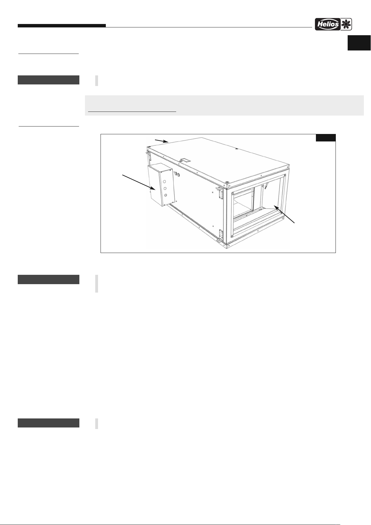
6.0 Konstruktiver Aufbau
Abluftstutzen
R
e
v
i
s
i
o
ns
k
l
a
p
p
(
b
e
i
d
s
e
Klemmenkasten
6.1 Montage – Einbau / Abhängepunkte
WARNUNG
Der schwere Deckel kann Sie stoßen oder Ihre Finger quetschen!
Sicherheitshandschuhe tragen, beim Öffnen nicht im Ausschwenkbereich des Deckels aufhalten!
ALB.. werden serienmäßig als komplette Einheit, d.h. anschlussfertig geliefert.
Nach Entfernen der Verpackung und vor Montagebeginn sind folgende Punkte zu überprüfen:
– liegen Transportschäden vor,
– gebrochene bzw. verbogene Teile
– Freilauf des Laufrades
– Die Befestigung erfolgt über vier L-förmige Montageprofile, die mit dem Gerätegehäuse verbunden sind. Die Montage
des Gerätes ist in allen laut Abb. 2 zulässigen Positionen möglich. Bei Ausblasstutzen nach oben (Ventilator oben),
bis Vorlauftemperatur +60 °C möglich. Bei Ausblasstutzen nach unten, ohne Beschränkung der Vorlauftemperatur
möglich. Für Filterreinigung-/austausch und Service auf gute Gerätezugänglichkeit achten.
– Die ALB.. können direkt in den/die Kanal/Rohrleitung montiert werden. Bei Bedarf ist der Körperschallübertragung
durch Verwendung von Schwingungsdämpfern und Segeltuchstutzen entgegenzuwirken (siehe Zubehör).
– Eine ausreichend lange, gerade Rohrstrecke (500 mm) vor und hinter dem Gerät ist zur Verhinderung von Leistungs -
minderung und Geräuscherhöhung vorzusehen.
– Das Gehäuse darf bei der Montage nicht deformiert oder verzogen werden, die ALB.. dürfen nur an ausreichend feste
und tragfähige Untergründe mit hierfür geeigneten Befestigungsmitteln montiert werden (Gewichtsangaben auf dem
Lüftungsgerät).
– Eine ausreichende Nachströmung abhängig vom eingesetzten Ventilator ist zu gewährleisten! Ggf. Anweisungen aus
DIN 1946-6 beachten.
e
i
t
i
g
)
Ansaugstutzen
Abb.1
ACHTUNG
Bei Installation unter abgehängten Decken muss eine Revisionsöffnung in Größe des Gehäusedeckels
vorgesehen werden.
13

Montage- und Betriebsvorschrift
R
EVISIONS-
Ö
FFNUNG
(BEIDSEITIG)
D
Außenluft-Boxen
Montagepositionen
(Blick auf Ausblasseite)
Abb.2
ACHTUNG
Abhängepunkte
B
59
L
Abb.3
Type B L O
59
ALB 220/4/50/30.. 652 1045 123
ALB 280/4/60/35.. 750 1085 153
O
6.2 Elektrischer Anschluss
Vor allen Wartungs- und Installationsarbeiten oder vor Öffnen des Anschlussraums ist das Gerät allpolig vom
Netz zu trennen und gegen unerwünschtes Wiedereinschalten zu sichern!
– Der elektrische Anschluss, bzw. die Inbetriebnahme darf nur von einer autorisierten Elektrofachkraft entsprechend
den Angaben im Gerät und den beiliegenden Anschlussplänen ausgeführt werden.
– Die einschlägigen Normen, Sicherheitsbestimmungen (z.B. DIN VDE 0100) sowie die Technischen Anschluss -
bedingungen der Energieversorgungsunternehmen sind unbedingt zu beachten!
– Ein allpoliger Netztrennschalter / Revisionsschalter mit mindestens 3 mm Kontaktöffnung (DIN EN 60335-1) ist für
Typen ..WW bereits montiert (Abb. 4). Für Typen ..EH ist ein zusätzlicher Revisionsschalter vor der Elektroheizung
vorzusehen. (Abb. 6).
– Netzform, Spannung und Frequenz müssen mit den Angaben des Typenschilds übereinstimmen.
– Bei Montage der elektrischen Zuleitungen ist zu beachten, dass bei Wasserbeaufschlagung kein Eindringen entlang
der Leitungen möglich ist.
– Zur Montage der Anschlusskabel dienen die seitlichen Durchführungen im Klemmenkasten. Bei Durchführung der
Kabel ist darauf zu achten, dass die elektrische Schutzart erhalten bleibt.
– Klemmenbezeichnungen entsprechen dem Anschlussplan im Klemmenkasten.
– Die Anschlüsse aller Steckverbindungen im Klemmenkasten müssen so ausgeführt sein, dass es nicht zur Beschädigung
kommt.
14

Montage- und Betriebsvorschrift
Außenluft-Boxen
D
Anschluss Schutzleiter (PE) über PE-Klemme (Abb. 5),
Anschluss der Stromzufuhr über Hauptschalter (Abb. 4):
1 ~ 230V L1/N/
3 ~ 400V L1/L2/L3/N/
(L1= Steuerphase)
ACHTUNG
ACHTUNG
ACHTUNG
Leitung nie über scharfe Kanten führen!
Stromzufuhr
1, L2, L3
L
Drehrichtung des angeschlossenen Ventilators überprüfen!
6.3 Anschluss des Warmwasser-Heizregisters (Typen ..WW)
Die Montage darf nur von einer Fachfirma durchgeführt werden, die gleichzeitig die Druckprobe der
Verbindung durchführt.
- Max. zulässige Wassertemperatur ist +90 °C
(das Warmwasser-Heizregister muss dampffrei sein).
- Max. zulässiger Wasserdruck 16 Bar.
- Wasseranschluss: Außengewinde G1.
- Die Geräte sind mit einem Frostschutzfühler ausgerüstet. Der Frostschutz ist bereits angeschlossen und eingestellt.
Voraussetzung für einwandfreie Funktion:
- Die angeschlossene Heizungsanlage muss immer Warmwasser bereitstellen.
Die Wärmebereitstellung während der Nachtabsenkung der Heizungsanlage ist sicherzustellen.
- Die Heizungsanlage darf nicht abgeschaltet werden (Urlaubszeit, Wochenende)
- Die Lüftungsanlage muss immer mit einer (elektrischen) Außenverschlussklappe ausgerüstet sein, damit kein
Kaltlufteinfall bei ausgeschalteter Lüftungsanlage möglich ist.
- Die ALB muss immer frostfrei aufgestellt sein.
- Wärmebereitstellung durch Nachtabsenkung der Heizungsanlage.
Abb.4 Abb.5 Abb.6
ACHTUNG
ACHTUNG
Bei abgeschalteter Netzspannung besteht Frostgefahr!
6.4 Anschluss externer Komponenten
6.4.1 Anschluss Bedienteil (Abb. 7)
Zum Starten des Lüftungsgeräts ist das Bedienteil anzuschließen.
- Entfernen der Sicherungsschraube vom unteren Teil des Bedienteils.
- Öffnen des Gehäuses des Bedienteils.
- Aussparung für das Kabel ausschneiden.
- Steuerleitung an die RJ-Buchse im Bedienteil anschließen.
- Bedienteil an einer Wand befestigen.
- Gehäuse schließen und mit der Schraube sichern.
- Das andere Ende der Steuerleitung an beliebige, freie RJ-Buchse
in der Platine der ALB anschließen.
- maximale Leitungslänge 50 m.
- Die Steuerleitung ist nur mit entsprechendem Abstand zu Netzleitungen zu führen.
- Der Steckverbinder muss beim Anschließen einrasten.
- Bei der Befestigung der Steuerleitung an die Wand o. ä. darf ihre Isolierung nicht beschädigt werden.
- Wird die Steuerleitung nicht direkt nach der Montage angeschlossen, müssen ihre Enden isoliert werden.
- Der Steckverbinder der Steuerleitung darf weder mit Wasser noch anderen Flüssigkeiten in Kontakt kommen.
RJ-Buchse
Abb.7
15
Montage- und Betriebsvorschrift
1
NC
=
Nor
m
al
gesch
l
osse
n
NO
=
n
or
m
al
geöf
f
n
e
t
COM
=
gem
e
i
n
sam
er
An
sch
l
u
ss
C
O
M
N
O
Schal
t
kont
akt
-
P
3
2
N
C
1
P
3
2
D
Außenluft-Boxen
6.4.2 Verbindung der Außenluftbox und Abluftsteuerung ALB-AS..
Wenn zusätzlich zum Hauptgerät ein Abluftgerät montiert wird, werden beide über ein gemeinsames Bedienteil geregelt, das am Hauptgerät montiert wird. Die Regelungen beider Einheiten werden mit einer Steuerleitung verbunden.
- Steuerleitung an den Stecker der Platine des Abluftgerätes anschließen.
- Das andere Ende der Steuerleitung an einer beliebigen RJ-Buchse der Platine des Hauptgerätes anschließen.
Die Netzleitungen werden zu jedem Gerät separat geführt.
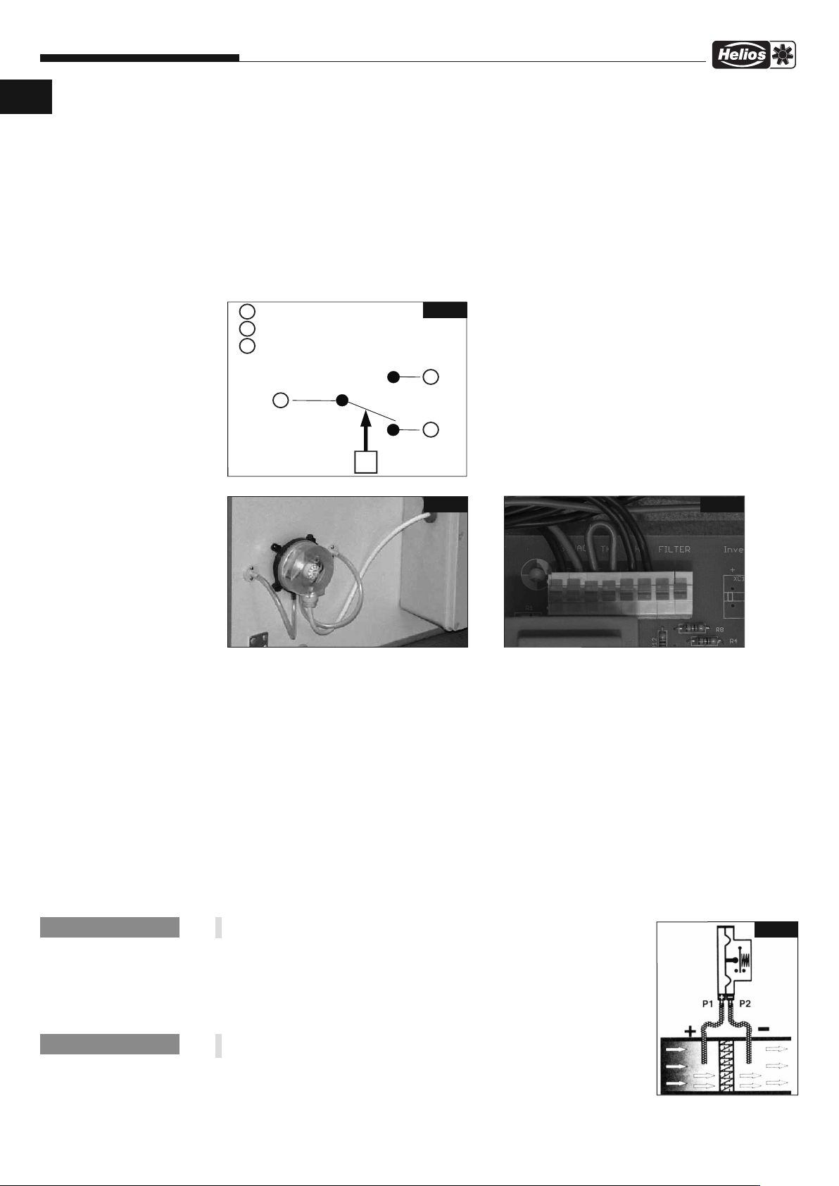
6.4.3 Anschluss: Druckdifferenz-Schalter DDS zur Filterüberwachung (Zubehör, Art.-Nr.: 0445 )
Spezifikation
Elektrische Belastung: Max. 1,5A (0,4 A) / 250 VAC.
Elektrische Schutzart: IP 54 mit geschlossenem Deckel.
Empfohlener Kabeldurchmesser 6 mm.
A
bb.8
Anschluss im Druckdifferenz-Schalter
Schaltschema für Druckdifferenz-Schalter DDS.
(Siehe auch Anschlussplan SS-1121 bis SS-1124, Punkt 1).
Schaltfunktionen:
Bei steigendem Differenzdruck:
1 öffnet
2 schließt
Bei fallendem Differenzdruck:
1 schließt
2 öffnet
bb.10
bb.9
A
-
-
+
+
A
Montageposition des DDS Anschluss im Klemmenkasten auf der Steuerplatine
Montage des DDS
1. Inhalt der Verpackung auf Vollständigkeit prüfen.
2. Für die Montage sind entsprechende Bohr-Markierungen am Gehäuse vorgesehen. In die äußeren Markierungen
zwei Löcher mit Æ 7 mm bohren.
3. Die Schlauchdurchführungen in die Bohrungen stecken und verschrauben.
4. Das Gehäuse des Druckdifferenz-Schalters aufschrauben.
5. Die Befestigungsschraube lösen und den Vorderdeckel abnehmen.
6. Den Gummischlauch in zwei Teile schneiden. Die Gummischläuche des Druckdifferenz-Schalters an den
Schlauchdurchführungen des Gerätegehäuses befestigen:
- Gummischlauch der Schlauchdurchführung 1 (vor dem Filter) auf die dunkelgraue Zuleitung 1 des DruckdifferenzSchalters aufstecken (Abb. 9).
- Gummischlauch der Schlauchdurchführung 2 auf die Zuleitung 2 des Druckdifferenz-Schalters aufstecken (Abb. 9).
7. Das mitgelieferte Kabel mit den Quetsch-Kabelschuhen in den Druckdifferenz-Schalter einführen und auf die Kontakte
1 u. 3 stecken.
8. Zur genauen Einstellung den Knopf (bei neuem Filter) drehen ± bis die Filteranzeige anspricht. Anschließend
auf den ca. 2-fachen Schaltwert (Ventilatordrehzahlstufe 5) einstellen.
HINW
EIS
☞
Die Filterüberwachung ist ab Ventilator-Drehzahlstufe 2 aktiv.
Abb.11
9. Den Vorderdeckel wieder auf den Druckdifferenz-Schalter stecken und Schraube
anziehen.
10. Das Anschlusskabel durch die seitliche Öffnung in den Klemmenkasten einführen.
Im Klemmenkasten das Kabel gemäß Anschlussplan SS-1121 bis SS-1124,
HINWEIS
☞
Punkt 1 anschließen.
In Flussrichtung des Volumenstromes wird der Anschluss P1 (+) vor
und der Anschluss P2 (-) nach dem Filter mit dem Luftkanal verbunden (Abb.11)
16

Montage- und Betriebsvorschrift
6.4.4 Anschluss: Umwälzpumpe
Siehe Anschlussplan SS 1121/1122, Punkt 17.
6.4.5 Anschluss: Mischeransteuerung
6.4.6 Anschluss: Außenluftklappe
Außenluft-Boxen
D
Siehe Anschlussplan SS 1121/1122, Punkt 9.
ACHTUNG
WARNUNG
Die Montage einer Rohrverschlussklappe (RSK..) in die Außenluftleitung ist zwingend erforderlich.
Bei ausgeschaltetem Gerät können so keine Frostschäden auftreten oder kalte Luft in das Gebäude gezogen werden!
Siehe Anschlussplan SS-1121 bis SS-1124, Punkt 16.
6.4.7 Anschluss: externer Schaltkontakt an ALB mit Warmwasser-Heizregister
Siehe Anschlussplan SS-1121/1122, Punkt 10.
6.4.8 Anschluss: externer Schaltkontakt an ALB mit Elektroheizung
Siehe Anschlussplan SS-1123/1124, Punkt 9.
6.4.9 Anschluss: Warmwasser-Heizung
Potentialfreier Schaltkontakt, siehe Anschlussplan SS-1121/1122, Punkt 14.
6.4.10 Anschluss: Indikation des Betriebszustandes
Potentialfreier Schaltkontakt, siehe Anschlussplan SS-1121/1122, Punkt 15 bzw. SS-1123/1124, Punkt 13.
6.4.11 Anschluss: Temperaturfühler Abluftgerät
Siehe Anschlussplan SS-1125/1126, Punkt 2 in der Montage- und Betriebsvorschrift des ALB-AS.. Abluftgerätes.
6.4.12 Anschluss: Modbus Schnittstelle
Siehe Anschlussplan SS-1121/1122 Punkt 13, Anschlussplan 1123/1124, Punkt 12.
Ein offenes Kommunikationsprotokoll als Dokument wird zur Verfügung gestellt, notwendige Peripherie ist bauseits zu stellen.
6.5 Inbetriebnahme
WARNUNG!
Das drehende Laufrad kann Ihre Finger quetschen/abschürfen.
Vor der Inbetriebnahme Berührungsschutz sicherstellen!
ACHTUNG
Folgende Kontrollarbeiten sind vor der Erstinbetriebnahme auszuführen bzw. zu prüfen:
– Bestimmungsgemäßen Einsatz der ALB überprüfen.
– Zulässige Fördermitteltemperatur prüfen.
– Netzspannung mit Leistungsschildangabe vergleichen.
– ALB auf fachgerechte elektrische Installation prüfen.
– Abdichtung des Anschlusskabels in den Klemmenkasten und festen Klemmsitz der Adern prüfen.
– Schutzleiteranschluss prüfen.
– Alle Teile, insbesondere Schrauben, Muttern, Schutzgitter auf festen Sitz überprüfen. Schrauben dabei nicht lösen!
– ALB auf Standsicherheit prüfen! Auf freie Zugänglichkeit zu Klemmenkasten und Revisionsdeckel ist zu achten.
– Sicherstellen, dass der Ansaug- und Ausblasbereich nicht für unbefugte Personen zugänglich ist.
– Dichtheit aller Verbindungen prüfen (falls erforderlich).
– Montagerückstände aus Ventilator bzw. Kanal entfernen.
– Freilauf und Drehrichtung des Laufrades prüfen; beim Prüfen Schutzbrille tragen.
– Saugseitige Rückschlagklappe muss freigängig sein.
– Stromaufnahme mit Leistungsschildangabe vergleichen.
– Beim Probelauf die ALB auf Vibrationen und Geräusche prüfen. Bei übermäßigen Vibrationen und/oder Geräuschen,
ist von einem Betrieb außerhalb des Betriebsbereichs der ALB auszugehen. In diesem Fall ist unbedingt Kontakt mit
dem Hersteller aufzunehmen!
– Die ALB nicht außerhalb der angegebenen Kennlinie (siehe Katalog / Internet) betreiben. Die ALB muss auf ihrem vor-
geschriebenen Betriebspunkt laufen.
– Durch Drehung des Revisionshauptschalters in Position 1 wird das Lüftungsgerät in den Standby-Modus gebracht.
Durch Drücken des Touch-Screens wird das Gerät eingeschaltet.
6.6 Inbetriebnahme ALB mit Warmwasser-Heizregister
Durch Inbetriebnahme des Lüftungsgerätes wird der Mischer mit Stellmotor (Anschlussplan SS-1121/1122, Punkt 9)
teilweise geöffnet. Die Umwälzpumpe wird eingeschaltet, sofern der Heizungsvorlauf über die Pumpenansteuerung
(Anschlussplan SS-1121/1122, Punkt 17) verwendet wird. Anschließend öffnen Ansaug- und Ausblasklappen (Zubehör;
bauseits) (Anschlussplan SS-1121/1122, Punkt 16) und der Ventilator wird eingeschaltet. Bei Abschalten der
ALB wird zuerst der Ventilator ausgeschaltet, die Klappen geschlossen und zuletzt wird die Umwälzpumpe abgestellt. Der Mischer wird nicht zugefahren, er bleibt in der Stellung. Die ALB wird durch das Warmwasser-Heizregister
aufgeheizt.
Wird der Frostschutz ausgelöst, schaltet das Gerät den Ventilator sofort aus und die Klappen werden
geschlossen. Der Mischer mit Stellmotor wird geöffnet, um den Wasserfluss durch den Wärmetauscher zu sichern.
17

Montage- und Betriebsvorschrift
D
Außenluft-Boxen
6.7 Inbetriebnahme ALB mit Elektroheizung
Durch Inbetriebnahme werden Ansaug- und Ausblasklappen geöffnet und der Ventilator wird eingeschaltet.
Die Regelung wird vom elektronischen Temperaturregelsystem mit den integrierten Temperaturfühlern und dem
Sollwertgeber übernommen. Die Regelung erfolgt stufenlos durch zeitproportionale Steuerung. Das Verhältnis zwischen
Ein- und Ausschaltzeit wird an den vorhandenen Leistungsbedarf angepasst. Die elektrische Heizung kann nur bei
eingeschaltetem Ventilator und Förderung eines Mindestvolumenstroms betrieben werden. Nach Ausschalten der
Steuerung durch das Bedienteil läuft der Ventilator in Abhängigkeit der Heizungstemperatur nach, um das Gerät
abzukühlen. Bei einer Temperaturüberschreitung wird die Elektroheizung durch den Überhitzungsthermostat
(selbstrückstellend) ab- und nach erfolgter Abkühlung wieder eingeschaltet. Reicht dies nicht aus, schaltet der
zusätzliche, nicht selbständig rückstellende Sicherheitsthermostat die Heizung dauerhaft aus (siehe Display
Fehlermeldung Error 6). Nach allpoligem Trennen vom Netz und Öffnen des Deckels kann durch Betätigen der beiden
Reset-Schalter (Abb. 12) der Sicherheitsthermostat zurückgestellt werden. Bei festgestelltem Fehler Error 6 wird der
Ventilator zur Abkühlung eingeschaltet.
bb.12
A
7
TEL
I
P
KA
NSTANDHAL
I
UNG
T
WAR
UND
UNG
T
ACHTUNG
6.8 Betrieb
Regelmäßig die einwandfreie Funktion der ALB prüfen:
– Freilauf des Laufrades.
– Stromaufnahme im Bereich der Typenschildangabe.
– Prüfung auf eventuelle Schwingungen und Geräusche.
– Ablagerungen von Staub und Schmutz im Gehäuse bzw. an Motor, Filter und Laufrad.
– Bei Problemen mit einem der oben aufgeführten Punkte, ist eine Wartung nach den Anweisungen aus Kapitel 7
durchzuführen.
7.0 Instandhaltung und Wartung
Vor allen Wartungs- und Installationsarbeiten oder vor Öffnen des Anschlussraums ist das Gerät allpolig vom
Netz zu trennen und gegen unerwünschtes Wiedereinschalten zu sichern!
• Übermäßige Ablagerungen von Schmutz, Staub, Fetten etc. auf Laufrad, Motor, Schutzgitter und vor allem zwischen
Gehäuse und Laufrad sind unzulässig, da sie zu Unwucht im Laufrad, Überhitzung des Motors oder zum Blockieren
des Laufrads führen können. In solchen Fällen ist das Gerät zu reinigen, siehe Punkt 7.2 Reinigung.
• Sofern das Gerät eine versorgungstechnisch wichtige Funktion übernimmt, ist eine einsatzabhängige regelmäßige
Wartung erforderlich. Im Falle längeren Stillstands ist bei Wiederinbetriebnahme eine Wartung durchzuführen.
• Zu prüfen sind:
– sichere Befestigung der ALB am Untergrund / an der Anlage im Zweifelsfall erneuern
– Schmutzablagerungen entfernen, siehe Reinigung 7.2
– mechanische Beschädigungen Gerät stilllegen, beschädigte Teile austauschen
– fester Sitz der Schraubverbindungen insbesondere Laufradbefestigung. Schrauben dabei nicht lösen!
– Gehäuseoberflächenbeschichtung (z.B. auf Rost, Lackschäden) ausbessern
– Freilauf des Laufrads ggf. reinigen oder Ventilator ersetzen
– Lagergeräusche Ventilator ersetzen
– Vibrationen siehe Fehlerbeschreibung 7.3
– Stromaufnahme entsprechend dem Typenschild siehe Fehlerbeschreibung 7.3
– Filterverschmutzung
– Freigängigkeit der Rückschlagklappe
7.1 Filterwechsel
Zuluftventilator:
Wenn im Hauptmenü des Bedienteils das Filterwechselsymbol eingeblendet wird, muss der Luftfilter des
Zuluftventilators getauscht werden. Anschließend muss der Betriebsstundenzähler durch Antippen des Symbols
zurückgesetzt werden. Falls in der Reinigungseinstellung im Konfigurationsmenü „ Druck“ ausgewählt wurde und ein
DDS Drucksensor am Filter des Zuluftventilators installiert und an der Gerätesteuerung angeschlossen ist (SS-11211124, Punkt 1), erlischt das Symbol nach erfolgtem Filterwechsel automatisch.
Abluftventilator:
Wenn im Hauptmenü des Bedienteils das Filterwechselsymbol mit einem „S“ eingeblendet wird, muss der Luftfilter
des Abluftventilators getauscht werden. Anschließend muss der Betriebsstundenzähler durch Antippen des Symbols
zurückgesetzt werden. Falls in der Reinigungseinstellung im Konfigurationsmenü „ Druck“ ausgewählt wurde und ein
DDS Drucksensor am Filter des Abluftventilators installiert und an der Abluftsteuerung angeschlossen ist (SS1125/1126, Punkt 1), erlischt das Symbol nach erfolgtem Filterwechsel automatisch.
18

Montage- und Betriebsvorschrift
7.2 Reinigung
Außenluft-Boxen
D
WARNUNG
WARNUNG
WARNUNG
WARNUNG!
Durch einen Isolationsfehler können Sie einen elektrischen Schlag bekommen!
Vor Beginn der Reinigung Ventilator allpolig vom Netz trennen und gegen Wiedereinschalten sichern!
WARNUNG!
Das drehende Laufrad kann Ihre Finger/Arme abtrennen oder einziehen!
Vor Beginn der Reinigung Ventilator allpolig vom Netz trennen und gegen Wiedereinschalten sichern!
– Durchströmungsbereich, Laufrad, Verstrebung und Motor des Ventilators säubern.
– Keine aggressiven, lacklösenden Mittel verwenden!
– Hochdruckreiniger oder Strahlwasser sind nicht gestattet!
7.3 Ersatzteile
Es sind ausschließlich Helios Originalersatzteile zu verwenden. Alle Reparaturen dürfen nur von autorisiertem/en
Fachpersonal/-Betrieben durchgeführt werden.
7.4 Stilllegen und Entsorgen
WARNUNG!
Bei der Demontage werden spannungsführende Teile freigelegt, die bei Berührung zu einem elektrischen
Schlag führen. Vor der Demontage Ventilator allpolig vom Netz trennen und gegen Wiedereinschalten sichern!
Die allgemein gültigen Arbeitsschutz- und Unfallverhütungsvorschriften sind einzuhalten!
– Elektroarbeiten dürfen nur von einer autorisierten Elektrofachkraft durchgeführt werden.
– Geeignete Hebewerkzeuge und Befestigungsvorrichtungen zum Demontieren des Ventilators verwenden,
Transportskizze beachten!
– Die Komponenten entsprechend den gültigen Vorschriften und Gesetzen entsorgen.
19

Montage- und Betriebsvorschrift
D
Außenluft-Boxen
7.5 Fehlerbeschreibung
Fehlermeldungen im Startbildschirm
Display Geräteverhalten Problem Lösung
as Gerät läuft
D
ERROR 1
ERROR 1
ERROR 1-2
ERROR 3
ERROR 4
ERROR 5
ERROR 6
ERROR 7
ERROR 8
ERROR 9
Das Gerät läuft nicht Frostschutz bei Warmwasser-
as Gerät läuft nicht
D
auptgerät läuft nicht,
H
Abluftgerät läuft
Das Gerät läuft nicht Defekt des Wassertemperaturfühlers
Das Gerät läuft nicht Defekt des Kanalfühlers oder Risiko
erät mit Warmwasser-
G
Heizregister läuft nicht
as Gerät läuft
D
Das Abluftgerät läuft
nicht (Das Hauptgerät
läuft)
Das Gerät läuft Defekt am Temperaturfühler des
Das Abluftgerät läuft
nicht
Das Gerät kann nicht
gestartet werden
Nach dem Einschalten
geht das Gerät sofort
wieder aus
Das Gerät ist laut/vibriert
Metallische Geräusche
aus dem Gerät
Gerät riecht verbrannt
Keine Funktion nach
dem Einschalten
berhitzung des Heizregisters
Ü
eizregister
H
Überhitzter Ventilator der
ußenluftbox
A
efekt am Thermokontakt des
D
Ventilators des Zuluftgerätes
efekte Sicherung der Elektronik
D
des Hauptgerätes
am Rücklauf
es Einfrierens des Gerätes
d
efekt des Temperaturfühlers
D
TE-4 Außenluft (schwarz)
Überhitzung der Elektroheizung Die Temp. am Sicherheitsfühler der Elektroheizung
Defekt des Elektronikschutzes
der Elektroheizung
Überhitzter Ventilator des
Abluftgerätes
Defekt am Thermokontakt des
Ventilators des Abluftgerätes
Abluftgerätes
Unterbrochenes Datenkabel Kontrollieren Sie die Ablufteinheit.
Defekte Sicherung der Elektronik
des Abluftgerätes
Unterbrochene Einspeisung Kontrolle, ob Stromausfall am Abluftgerät vorliegt.
Loser Anschluss des Stromkabels Kontrolle des Stromkabels
Serviceschalter steht in Position 0 Kontrolle, ob Serviceschalter in der Stellung I ist.
Spannungsausfall / Spannung er-
reicht nicht die erforderlichen Werte
Der Leitungsschutzschalter
(Sicherung) ist unterdimensioniert
Es kam zu einem Kurzschluss Kontrolle aller Elektroanschlüsse der Einheit,
Die Luftfilter sind verschmutzt Kontrolle der Luftfilter. Falls diese verschmutzt sind
Zuluft- oder Abluftrohre sind verstopft
Das Rad des Ventilators ist locker
oder beschädigtes Motorlager
Überhitzte Komponenten Kommt zu Beginn des Winterbetriebs vor. Geruch
Verbrannter Staub auf
Elektroheizung
Antifrostschutz aktiv Erneuter Versuch nach einigen Minuten. Ansonsten
ontrolle, ob die Luft im Gerät frei zirkulieren kann,
K
as Heizregister wird nicht genügend gekühlt.
d
Kontrolle, ob Temp. im Kanal nicht < 8°C bei einer
ußentemperatur von < 10°C ist.
A
Fehlersuche am Motor: fehlerhafte Lager, Kurz -
chluss, erhöhte Stromaufnahme, geringe Belastung
s
es Ventilators (Leerlauf), Filter verschmutzt. Gerät
d
icht einschalten, bis der Fehler behoben ist.
n
ontrolle, ob Leitung zum Motor-Thermokontakt
K
unterbrochen ist oder ob Ventilatormotor überhitzt.
echsel der Sicherung an der Elektronik des
W
Hauptgerätes.
Kontrolle, ob der Fühler richtig befestigt ist. Fühler
wechseln, falls defekt.
Kontrolle, ob der Fühler richtig befestigt ist. Fühler
echseln, falls beschädigt. Wenn das Gerät mit ei-
w
nem Warmwasser-Heizregister ausgerüstet ist
und die Temperatur im Kanal < 8°C ist, handelt es
sich um den Frostschutz. Nach erneuter
Temperaturerhöhung erlischt die Fehlermeldung.
ontrolle, ob der Fühler richtig befestigt ist. Fühler
K
wechseln, falls beschädigt.
bersteigt 60°C. Überhitzungsgrund feststellen
ü
(evtl. verschmutzter Filter).
Kontrolle, ob der Fühler richtig befestigt ist. Fühler
wechseln, falls beschädigt.
Fehlersuche am Motor: fehlerhafte Lager,
Kurzschluss, erhöhte Stromaufnahme, geringe
Belastung des Ventilators (Leerlauf). Gerät nicht
einschalten, bis der Fehler behoben ist.
Kontrolle, ob Leitung zum Motor-Thermokontakt
unterbrochen ist oder ob Ventilatormotor überhitzt.
Kontrolle, ob der Fühler richtig an den Klemmen
der Regulierung des Abluftgerätes befestigt ist.
Fühler wechseln, falls defekt. Wenn dieser Fühler
defekt ist, regelt das Zuluftgerät die Temperatur
nach dem Fühler im Bedienteil.
Wechseln Sie die Sicherung an der Elektronik des
Abluftgerätes.
Spannung an der Verbindung zum Hauptanschluss
prüfen.
Kontrolle, ob der richtige Typ und die richtige
Leistung des Leitungsschutzschalters benutzt wurde.
Motoren, Vorwärmer, Zuleitungskabel und externer
Komponenten auf einen Kurzschluss.
und dies nicht im Display angezeigt wird, mus eine
neue Filtereinheit installiert werden.
Kontrolle des Rohrsystems (verstopfte Ansaug jalousien/Verteilelemente, geschlossene Klappen...)
Kontrolle, ob der Ventilator frei dreht. Beschädigten
Ventilator austauschen.
verflüchtigt sich bei regelmäßiger Filterreinigung.
Mangelhafte Filterwartung kann zu
Staubablagerungen auf der Elektroheizung führen.
auf ausreichenden Warmwasser-Zufluss prüfen.
Wassertemperatur im Anzeigemenü prüfen - Gerät
läuft erst ab 30°C an.
20

Montage- und Betriebsvorschrift
KAPITEL 8
SCHALTPLÄNE
ALB220/4/50/30 WW
Anschlussplan SS-1121
Außenluft-Boxen
D
21

Montage- und Betriebsvorschrift
D
LB220/4/50/30 EH
A
Außenluft-Boxen
Anschlussplan SS-1123
22

Montage- und Betriebsvorschrift
LB280/4/60/35 WW
A
Anschlussplan SS-1122
Außenluft-Boxen
D
23

Montage- und Betriebsvorschrift
D
LB280/4/60/35 EH
A
Außenluft-Boxen
Anschlussplan SS-1124
24

Montage- und Betriebsvorschrift
Notizen:
Außenluft-Boxen
D
25

Als Referenz am Gerät griffbereit aufbewahren! Druckschrift-Nr. 91832/06.16
Service und Information
D HELIOS Ventilatoren GmbH + Co KG · Lupfenstraße 8 · 78056 VS-Schwenningen F HELIOS Ventilateurs · Le Carré des Aviateurs · 157 av. Charles Floquet · 93155 Le Blanc Mesnil Cedex
CH HELIOS Ventilatoren AG · Tannstrasse 4 · 8112 Otelfingen GB HELIOS Ventilation Systems Ltd. · 5 Crown Gate · Wyncolls Road · Severalls Industrial Park ·
A HELIOS Ventilatoren · Postfach 854 · Siemensstraße 15 · 6023 Innsbruck Colchester · Essex · CO4 9HZ
www.heliosventilatoren.de

Helios Ventilation Systems
INSTALLATION AND OPERATING INSTRUCTIONS NO. 91832
Helios Fresh Air Boxes
UK
ALB..
ALB-220/4/50/30 WW/EH
ALB-280/4/60/35 WW/EH

ENGLISH
Table of Contents
CHAPTER 1. SAFETY . . . . . . . . . . . . . . . . . . . . . . . . . . . . . . . . . . . . . . . . . . . . . . . . . . . . . . . . . . . . . . . . . . . . . . Page 1
1.0 Important information . . . . . . . . . . . . . . . . . . . . . . . . . . . . . . . . . . . . . . . . . . . . . . . . . . . . . . . . . . . . . . . . . . . Page 1
1.1 Warning instructions . . . . . . . . . . . . . . . . . . . . . . . . . . . . . . . . . . . . . . . . . . . . . . . . . . . . . . . . . . . . . . . . . . . Page 1
1.2 Safety instructions . . . . . . . . . . . . . . . . . . . . . . . . . . . . . . . . . . . . . . . . . . . . . . . . . . . . . . . . . . . . . . . . . . . . . Page 1
1.3 Application . . . . . . . . . . . . . . . . . . . . . . . . . . . . . . . . . . . . . . . . . . . . . . . . . . . . . . . . . . . . . . . . . . . . . . . . . . . Page 2
1.4 Boundaries . . . . . . . . . . . . . . . . . . . . . . . . . . . . . . . . . . . . . . . . . . . . . . . . . . . . . . . . . . . . . . . . . . . . . . . . . . Page 2
1.5 Protection against contact . . . . . . . . . . . . . . . . . . . . . . . . . . . . . . . . . . . . . . . . . . . . . . . . . . . . . . . . . . . . . . . Page 3
1.6 Personnel qualification . . . . . . . . . . . . . . . . . . . . . . . . . . . . . . . . . . . . . . . . . . . . . . . . . . . . . . . . . . . . . . . . . . Page 3
1.7 Air-flow direction and direction of rotation . . . . . . . . . . . . . . . . . . . . . . . . . . . . . . . . . . . . . . . . . . . . . . . . . . . Page 3
1.8 Motor protection . . . . . . . . . . . . . . . . . . . . . . . . . . . . . . . . . . . . . . . . . . . . . . . . . . . . . . . . . . . . . . . . . . . . . . Page 3
1.9 Frost protection . . . . . . . . . . . . . . . . . . . . . . . . . . . . . . . . . . . . . . . . . . . . . . . . . . . . . . . . . . . . . . . . . . . . . . . Page 3
1.10 Functional safety – Emergency operation . . . . . . . . . . . . . . . . . . . . . . . . . . . . . . . . . . . . . . . . . . . . . . . . . . . . Page 3
CHAPTER 2. GENERAL INFORMATION . . . . . . . . . . . . . . . . . . . . . . . . . . . . . . . . . . . . . . . . . . . . . . . . . . . . . . . Page 4
2.0 Warranty claims – Exclusion of liability . . . . . . . . . . . . . . . . . . . . . . . . . . . . . . . . . . . . . . . . . . . . . . . . . . . . . . Page 4
2.1 Certificates-Guidelines . . . . . . . . . . . . . . . . . . . . . . . . . . . . . . . . . . . . . . . . . . . . . . . . . . . . . . . . . . . . . . . . . . Page 4
2.2 Shipping . . . . . . . . . . . . . . . . . . . . . . . . . . . . . . . . . . . . . . . . . . . . . . . . . . . . . . . . . . . . . . . . . . . . . . . . . . . . Page 4
2.3 Receipt . . . . . . . . . . . . . . . . . . . . . . . . . . . . . . . . . . . . . . . . . . . . . . . . . . . . . . . . . . . . . . . . . . . . . . . . . . . . . Page 4
2.4 Storage . . . . . . . . . . . . . . . . . . . . . . . . . . . . . . . . . . . . . . . . . . . . . . . . . . . . . . . . . . . . . . . . . . . . . . . . . . . . . Page 4
2.5 Performance data . . . . . . . . . . . . . . . . . . . . . . . . . . . . . . . . . . . . . . . . . . . . . . . . . . . . . . . . . . . . . . . . . . . . . Page 4
2.6 Noise data . . . . . . . . . . . . . . . . . . . . . . . . . . . . . . . . . . . . . . . . . . . . . . . . . . . . . . . . . . . . . . . . . . . . . . . . . . . Page 4
CHAPTER 3. TECHNICAL DATA . . . . . . . . . . . . . . . . . . . . . . . . . . . . . . . . . . . . . . . . . . . . . . . . . . . . . . . . . . . . . . Page 4
3.0 Technical data . . . . . . . . . . . . . . . . . . . . . . . . . . . . . . . . . . . . . . . . . . . . . . . . . . . . . . . . . . . . . . . . . . . . . . . . Page 4
3.1 Accessories . . . . . . . . . . . . . . . . . . . . . . . . . . . . . . . . . . . . . . . . . . . . . . . . . . . . . . . . . . . . . . . . . . . . . . . . . . Page 5
3.2 Dimensions . . . . . . . . . . . . . . . . . . . . . . . . . . . . . . . . . . . . . . . . . . . . . . . . . . . . . . . . . . . . . . . . . . . . . . . . . . Page 5
CHAPTER 4. FUNCTION / OPERATION . . . . . . . . . . . . . . . . . . . . . . . . . . . . . . . . . . . . . . . . . . . . . . . . . . . . . . . . Page 6
4.0 Functional description ALB.. . . . . . . . . . . . . . . . . . . . . . . . . . . . . . . . . . . . . . . . . . . . . . . . . . . . . . . . . . . . . . Page 6
4.1 Controller settings . . . . . . . . . . . . . . . . . . . . . . . . . . . . . . . . . . . . . . . . . . . . . . . . . . . . . . . . . . . . . . . . . . . . . Page 6
4.2 Menu structure . . . . . . . . . . . . . . . . . . . . . . . . . . . . . . . . . . . . . . . . . . . . . . . . . . . . . . . . . . . . . . . . . . . . . . . . Page 6
4.3 User interface . . . . . . . . . . . . . . . . . . . . . . . . . . . . . . . . . . . . . . . . . . . . . . . . . . . . . . . . . . . . . . . . . . . . . . . . . Page 7
4.4 Parameter settings . . . . . . . . . . . . . . . . . . . . . . . . . . . . . . . . . . . . . . . . . . . . . . . . . . . . . . . . . . . . . . . . . . . . Page 12
CHAPTER 5. USER MAINTENANCE . . . . . . . . . . . . . . . . . . . . . . . . . . . . . . . . . . . . . . . . . . . . . . . . . . . . . . . . . Page 13
5.0 User maintenance . . . . . . . . . . . . . . . . . . . . . . . . . . . . . . . . . . . . . . . . . . . . . . . . . . . . . . . . . . . . . . . . . . . . Page 13
CHAPTER 6. INSTALLATION AND COMMISSIONING . . . . . . . . . . . . . . . . . . . . . . . . . . . . . . . . . . . . . . . . . . . Page 13
6.0 Design . . . . . . . . . . . . . . . . . . . . . . . . . . . . . . . . . . . . . . . . . . . . . . . . . . . . . . . . . . . . . . . . . . . . . . . . . . . . . Page 13
6.1 Installation – Installation / suspension points . . . . . . . . . . . . . . . . . . . . . . . . . . . . . . . . . . . . . . . . . . . . . . . . Page 13
6.2 Electrical connection . . . . . . . . . . . . . . . . . . . . . . . . . . . . . . . . . . . . . . . . . . . . . . . . . . . . . . . . . . . . . . . . . . Page 14
6.3 Connection of warm water heater battery . . . . . . . . . . . . . . . . . . . . . . . . . . . . . . . . . . . . . . . . . . . . . . . . . . Page 15
6.4 Connection of external components . . . . . . . . . . . . . . . . . . . . . . . . . . . . . . . . . . . . . . . . . . . . . . . . . . . . . . Page 15
6.5 Commissioning . . . . . . . . . . . . . . . . . . . . . . . . . . . . . . . . . . . . . . . . . . . . . . . . . . . . . . . . . . . . . . . . . . . . . . Page 17
6.6 Commissioning the ALB with a warm water heater battery . . . . . . . . . . . . . . . . . . . . . . . . . . . . . . . . . . . . . Page 17
6.7 Commissioning the ALB with electric heater . . . . . . . . . . . . . . . . . . . . . . . . . . . . . . . . . . . . . . . . . . . . . . . . Page 18
6.8 Operation . . . . . . . . . . . . . . . . . . . . . . . . . . . . . . . . . . . . . . . . . . . . . . . . . . . . . . . . . . . . . . . . . . . . . . . . . . . Page 18
CHAPTER 7. SERVICING AND MAINTENANCE . . . . . . . . . . . . . . . . . . . . . . . . . . . . . . . . . . . . . . . . . . . . . . . . Page 18
7.0 Servicing and maintenance . . . . . . . . . . . . . . . . . . . . . . . . . . . . . . . . . . . . . . . . . . . . . . . . . . . . . . . . . . . . . Page 18
7.1 Filter change . . . . . . . . . . . . . . . . . . . . . . . . . . . . . . . . . . . . . . . . . . . . . . . . . . . . . . . . . . . . . . . . . . . . . . . . Page 18
7.2 Cleaning . . . . . . . . . . . . . . . . . . . . . . . . . . . . . . . . . . . . . . . . . . . . . . . . . . . . . . . . . . . . . . . . . . . . . . . . . . . . Page 19
7.3 Spare parts . . . . . . . . . . . . . . . . . . . . . . . . . . . . . . . . . . . . . . . . . . . . . . . . . . . . . . . . . . . . . . . . . . . . . . . . . Page 19
7.4 Standstill and disposal . . . . . . . . . . . . . . . . . . . . . . . . . . . . . . . . . . . . . . . . . . . . . . . . . . . . . . . . . . . . . . . . . Page 19
7.5 Error description . . . . . . . . . . . . . . . . . . . . . . . . . . . . . . . . . . . . . . . . . . . . . . . . . . . . . . . . . . . . . . . . . . . . . Page 20
CHAPTER 8. WIRING DIAGRAMS . . . . . . . . . . . . . . . . . . . . . . . . . . . . . . . . . . . . . . . . . . . . . . . . . . . . . . . . . . . Page 21
Expiry of service life, disposal
Parts and components of the fan, whose service life has expired, e.g. due to wear and tear, corrosion, mechanical load, fatigue and/or other effects that cannot be
directly discerned, must be disposed of expertly and properly after disassembly in accordance with the national and international laws and regulations. The same also
applies to auxiliary materials in use. Such as oils and greases or other substances.
The intended and unintended further use of worn parts, e.g. impellers, rolling bearings, filters, etc. can result in danger to persons, the environment as well as machines
and systems. The corresponding operator guidelines applicable on-site must be observed and used.

Installation and Operating Instructions
CHAPTER 1
SAFETY
1.0 Important information
In order to ensure complete and effective operation and for your own safety, all of the following instructions should be
read carefully and observed. This document should be regarded as part of the product and as such should be kept
accessible and durable. The operator is responsible for observing all plant-related safety regulations.
Fresh Air Boxes
UK
DANGER
WARNING
CAUTION
1.1 Warning instructions
These symbols are safety-relevant prominent warning symbols. All safety
regulations and/or symbols in must be absolutely adhered to, so that any
risks of injury and dangerous situations are avoided!
1.2 Safety instructions
Special regulations apply for use, connection and operation; consultation is required in case of doubt. Further information can be found in the relevant standards and legal texts.
Protective glasses
l
Serves to protect against eye injuries.
Ear protectors
p
Serves to protect against all kinds of noise.
Protective clothing
r
Primarily serves to protect against contact with moving parts.
Do not wear rings, chains or other jewellery.
Protective gloves
n
Protective gloves serve to protect the hands against rubbing, abrasions, cuts
or more profound injuries, as well as contact with hot surfaces.
Protective footwear
m
Protective footwear serves to protect against heavy falling parts and from slipping on slippery surfaces.
Hair net
The hair net primarily serves to protect long hair against contact with moving
parts.
With regard to all work on the fan, the generally applicable safety at work
and accident prevention regulations must be observed
• All electrical work and the commissioning must only be carried out by authorised, qualified electricians! Installation, servicing and maintenance work
must only be carried out by suitable specialist personnel!
• An all-pole mains switch / isolator, with at least a 3 mm contact (EN
60335-1) is installed for types ..WW. An additional isolator is necessary before the electric heater for types ..EH.
• The following must be observed before all cleaning, maintenance and
installation work or before opening the terminal compartment:
- Isolate the device from the mains power supply!
- The rotating parts must first come to a standstill!
- The unit must be secured against being switched on again!
!
1

Installation and Operating Instructions
UK
Fresh Air Boxes
• Do not open unit cover when the unit is in operation!
• Transport fan in packaging until installation!
• Only transport fans using means of transport that are appropriate for the
weight, wear protective gloves during transport!
• Wear protective gloves/footwear when unpacking the unit.
• Ensure the suitable load capacity and properties of the mounting surface and
use suitable mounting material.
• The operator is responsible for observing all plant-related safety regulations!
• Abnormally frequent activation/deactivation is not permissible.
• Protection against contact for the impeller must be ensured pursuant to DIN
EN 13857.
• The planner and operator must ensure easy access for inspection and cleaning work!
• A uniform inflow and free outlet must be ensured.
• When using a vented fire place (chimney) in a ventilated room, there must be
sufficient supply air for all operating conditions (consult chimney sweep).
Frost protection information
The fresh air boxes ALB type ..WW have a built-in warm water heater battery.
In order to avoid frost damage, heating water must always be available. The
heating system must be always in operation even if the ventilation system is
turned off. In order to guarantee that no cold outside air below +5 °C arrives
at the heat exchanger, an external damper must always be integrated in the
ventilation system.
1.3 Application
– Normal use:
Especially for in-line installation in circular ducting designed and for versatile commercial applications. The units are suitable for the use in dry interior rooms at temperatures from +5 °C to +35 °C. They are suitable for moving clean air
without dust, grease, chemical evaporation and other pollution.
- Max. relative humidity: 80%
- Electrical protection class: IP 20
The units are designed only for installation in frost-protected rooms. Frost and water damages may occur if installed
outdoors.
– Reasonably foreseeable misuse:
The fans are not suitable for operation under difficult conditions, such as high levels of humidity, aggressive media,
long standstill periods, heavy contamination, excessive loads due to climatic, technical or electronic influences. The
same applies for the mobile use of fans (vehicles, aircraft, ships, etc.).
– Improper, prohibited use:
Outdoor installation without effective weather protection or in direct contact with water. Conveyance of explosive gas
mixtures/media. Installation in an explosive area/atmosphere. Operation without standardised safety devices (e.g. protective grille). Conveyance of solids or solid content > 10 µm in the conveyed medium and liquids. Conveyance of abrasive and/or fan material-corrosive media. Conveyance of conveyed medium containing fat.
1.4 Boundaries
Spatial boundaries:
A straight, flat pipe section of 500 mm must be ensured before and after the ALB. When using a pipeline at the start,
the air inlets with a damper (VK, WSG accessories) must be used. When using a pipeline at the end, a protection grill-
e must be used on the outlet side.
The outlet-side environment must not be accessible to unauthorised persons and obstructed.
The fan must be easily accessible for cleaning and maintenance purposes, particularly the terminal box.
Power supply interface:
- Connection only with permanently installed lines according to wiring diagram
2

Installation and Operating Instructions
1.5 Protection against contact
The generally applicable safety at work and accident prevention regulations must be observed for installation!
The operator is responsible for observing these regulations!
– Contact with rotating parts must be avoided.
– Protection against contact may be necessary on the suction side depending on the installation conditions.
– Fans which are protected by their installation method (e.g. installation in ventilation ducts or closed assemblies) do
1.6 Personnel qualification
– All electrical work as well as the start-up must only be carried out by qualified electricians
– ALB can be used by children over the age of 8 as well as persons with physical, sensory, or mental disabilities or lack
1.7 Air-flow direction and direction of rotation
Fresh Air Boxes
UK
Appropriate protection grilles are available as accessories.
not require protection guards if the plant provides the necessary level of safety. Please note that the operator is
responsible for complying with the current standard (DIN EN 13857) and can be held liable for accidents as a consequence of missing protection systems.
of experience and knowledge, if they are supervised or instructed with regard to the safe use of the unit and they understand the resulting risks. Children must not play with the unit. Cleaning or user maintenance must not be carried
out by unsupervised children.
WARNING
WARNING
ATTENTION
WARNING
Parts ejected from the fan may damage your eyes!
Wear protective glasses when checking the direction of rotation!
WARNING
The rotating impeller can sever or trap your fingers/arms!
Operation only with mounted safety fittings!
Risk of damage!
Do not insert objects into the rotating impeller.
Air-flow direction and direction of rotation must correspond to the arrows on the unit.
The direction of rotation may only be checked when the fan is switched off and coasting.
Incorrect rotation direction can lead to the motor overheating!
1.8 Motor protection
– 1-phase motors
All 1-phase motors have thermal contacts, which are wired in series with the coil and switch off automatically and re-
start after cooling.
– 3-phase motors
All 3-phase motors have thermal contacts, which are monitored by the controller. When the thermal contacts are trig-
gered, the controller will disconnected the motor.
1.9 Frost protection
The fresh air boxes ALB 220/4/50/30.. and ALB 280/4/60/35.. are equipped with a frost protection mechanism.
In order for this mechanism to be effective, the following important points must be fulfilled:
- The units must only be installed indoors.
- Minimum ambient temperature +5 °C.
- ALB must never be switched off or be disconnected from the mains.
- The heating system must always be in operation.
- The flow temperature must be checked.
- A sufficient warm water supply must be guaranteed for types ..WW.
- An airtight damper (electrical) is mandatory.
- Regular maintenance and functional tests must be carried out.
- If the unit is put out of operation, the warm water heater battery must be emptied.
- If operated with an additional extract fan it must be ensured that the damper closes in case of a malfunction.
- In case of malfunctions, maintenance work, error tracing, etc., the warm water heater battery must be emptied at
low outside temperatures.
1.10 Functional safety – Emergency operation
When using the fan in an important supply function, the plant is to be designed so that emergency operation is automatically guaranteed in case of fan failure. Suitable solutions are, for example,: parallel operation of two less powerful
units with a separate electric circuit, standby fan, alarm systems and emergency ventilation systems.
3

Installation and Operating Instructions
UK
CHAPTER 2
GENERAL INFORMATION
Fresh Air Boxes
2.0 Warranty claims – Exclusion of liability
All versions of this documentation must be observed, otherwise the warranty shall cease to apply. The same applies
to liability claims against Helios. The use of accessory parts, which are not recommended or offered by Helios, is not
permitted. Any possible damages are not covered by the warranty. Changes and modifications to the unit are not permitted and lead to a loss of conformity, and any warranty and liability shall be excluded in this case.
2.1 Certificates - Guidelines
If the product is installed correctly and used to its intended purpose, it conforms to all applicable provisions and EU
guidelines at its date of manufacture.
2.2 Shipping
The ALB is packed ex works in such a way that it is protected against normal transport strain. Carry out the shipping
carefully. It is recommended to leave the fan in the original packaging. The ALB must be kept in the housing or lugs
provided (if applicable) for transportation or installation. Only use appropriate lifting equipment and fastening devices,
which have a load capacity of at least the corresponding weight. Weight specifications according to the delivery note
or information on the unit..
ATTENTION
ATTENTION
Do not transport fan on the connection cables, terminal box or impeller!
Do not stand under suspended loads!
2.3 Receipt
The shipment must be checked for damage and correctness immediately upon delivery. If there is any damage,
promptly report the damage with the assistance of the transport company. If complaints are not made within the agreed
period, any claims could be lost.
2.4 Storage
When storing for a prolonged time, the following steps are to be taken to avoid damaging influences: Motor protection by
dry, airtight and dust-proof packaging (plastic bag with desiccant and humidity indicators). Vibration-free, water-tight and
constant-temperature storage at a temperature in the range -20 °C to +40 °C, which must not be exceeded.
In case of storage below 0 °C, the unit must be left in standby mode under operating conditions for at least 2
hours before commissioning, so that the internal temperature can equalise.
In case of a storage period of more than three months or motor standstill, maintenance must be carried out before startup. In case of reshipment (above all, over longer distances; e.g. by sea), it must be checked whether the packaging is suitable for the form and route of transport. Damages due to improper transportation, storage or putting into operation are
not liable for warranty.
2.5 Performance data
The fan or motor type plate gives an indication of the mandatory electrical values; which must be coordinated with the
local supply network. The fan performances* were established on a test stand according to DIN EN ISO 5801: 201012; they apply to the nominal speed and standard design using an inlet nozzle, without a protection guard with unhindered inflow and outflow and a pressure-side pipe section with 2.5x diameter length. Different versions and unfavourable installation and operating conditions can lead to a reduction of output.
CHAPTER 3
TECHNICAL DATA
* (performance and noise data from the
currently applicable Helios documentation
and the internet)
2.6 Noise data
The noise data* also refers to the aforementioned directive. Casing variations, unfavourable operating conditions and
many other things can lead to an increase in the specified catalogue values. Data that refers to certain distances (1, 2,
4 m) apply to free field conditions. With regard to installation, the sound pressure level can differ significantly from the
catalogue data, as it is highly dependant on the installation conditions, i.e. on the absorption capability of the room, the
room size among other factors.
3.0 Technical data
ALB 220/4/50/30 WW ALB 280/4/60/35 WW
Voltage, frequency 230 V, 50 Hz, 1~ 400 V, 50 Hz, 3 ~
Rated current max. [A] 6.1 2.75
Protection class IP 20 IP 20
Speed max. [1/min] 1460 1450
Output free-clowing [m³/h] 3200 4700
Ambient temperature min/max [°C] + 5/+ 35 + 5/+ 35
Temperature class 155 155
Weight approx. kg 80 110
4

Installation and Operating Instructions
3.1 Accessories
Spare and pollen filter ELF-ALB 220/4/50/30 G4 / 3646
Hydraulic unit WHSH EH 24 V (0-10V) / 8318
Differential pressure switch DDS / 0445
Symmetrical adaptor ALB-ÜS 220/4/50/30 / 7515 ALB-ÜS 280/4/60/35 / 7516
Flexible mounting clamp FM 315 / 1674 FM 355 / 1675
Bracket flange ring FR 315 / 1204 FR 355 / 1205
Connection cable (extra-long) ALB-SK 30 / 2517 – 30 metres long
CO
Exhaust air control incl. duct temp. sensor
and connection cable (10 m)
Connection cable branching
(max. cable length 50 m)
Other accessories can be found in the current catalogue.
Fresh Air Boxes
ALB 220/4/50/30 WW / Ref. no. ALB 280/4/60/35 WW / Ref. no.
ELF-ALB 280/4/60/35 G4 / 3649
ELF-ALB 220/4/50/30 M5 / 3647
ELF-ALB 220/4/50/30 F7 / 3648
ALB-SK 50 / 2518 – 50 metres long
/humidity sensor KWL-CO2/ 4272
2
ALB-ASW 220/4/50/40 / 3655 ALB-ASD 280/4/60/35 / 3656
KWL-FTF / 4273
KWL-ALA / 9960
ELF-ALB 280/4/60/35 M5 / 3650
ELF-ALB 280/4/60/35 F7 / 3654
UK
3.2 Dimensions
ALB 220/4/50/30..
All dimensions in mm
ALB 280/4/60/35..
All dimensions in mm
5

U
K
I
4
TER
P
A
H
C
ON
I
T
RA
E
OP
/
ON
I
T
C
N
U
F
4.0
4.1
tar
S
Activate unit
Touch touch-screen lightly
t s
u
F
The
nd
a
s r
i
o
C
creen
Fr
n
o
cti
n
sh
e
Fr
t
a
he
e
r
ui
q
e
l
l
tro
n
ir
A
h
s
e
cr
des
al
oxe
B
r
i
A
sp
a
o
t
d
e
he
t
he
. W
d
g
n
etti
s
er
☛
= selectable element
☛
re
ctu
u
tr
s
u
Men
4.2
i
B
pti
s
s
e
ox
..
B
L
A
n
o
om
r
f
..
LB
A
s
e
r
m
e
t
d
e
i
f
i
c
st
e
r
n a
i
s
o
i
l
e
H
e
ur
t
a
r
e
p
, b
nt
a
ur
a
➀
p
. The
out
ov
r
q
i
➃➅
ue
e
d
i
LB
A
or
nt
sa
a
e
l
p
a
ot
a
e
d
i
e
r
a
om
c
r
he
i
l
c
m
o
o
r
b
a
t
sui
y
l
l
a
i
c
r
e
m
➆
➁
➧
➂
➄
➇
sup
y
b
e
t
a
m
l
l
oom
r
l
l
a
or
f
e
s.
a
e
r
a
➀ Main menu
➁ Time
➂ Power-Off
➃ Timer active
➄ Warning symbol/Error message
➅ Night mode active
➆ Position/Temp. control sensor
➇ Fan stage (1-5 or automatic mode)
xt
e
ng
i
y
l
p
n whi
s, i
sh
e
r
f
l
rna
e
h c
c
nd
n a
a
e
l
h
c
whi
,
r
i
a
d
e
t
a
he
d
e
r
e
t
l
i
f
s
i
r
i
sh a
e
r
f
g
n
erati
p
O
d
an
n
o
ati
l
tal
s
n
6

I
4.3 User interface
Setting the setpoint temperature
Setting the setpoint temperature in the range from 5-30°C in 1°C steps.
☛
Setting the fan stage
Setting the fan stage 1-5
➧
➧
Fr
➁
➂
➁
ir
A
h
s
e
B
s
e
ox
➀ Set setpoint temperature
➁ Position/Temp. sensor*
➂ Confirm and back
➀
➀ Set fan stage
➁ Confirm and back
➀
g
n
erati
p
O
d
an
n
o
ati
l
tal
s
n
☛
If automatic mode is activated (see configuration menu “device mode”), this will be signalled by a superimposed “A” on the start screen.
After selecting a manual fan stage on the start screen, the unit will
return to automatic mode after 30 minutes.
☛
Night mode active
Activation/deactivation in the configuration menu. Active night mode can be ended prematurely by pressing
the fan symbol (until the next switching cycle).
➀ End night mode prematurely
➁ Confirm and back
*Display current sensor
Sensor in control unit
Sensor supply air
Sensor extract air
Setting sensor position:
Configuration menu
U
K
➧
☛
Error key
In case of a superimposed warning symbol, switch to the error message by tapping the screen.
➁➀
Error description:
see section 4.4
➧
☛
Display filter change
In case of a superimposed filter change symbol, the air filter must be replaced. The operating hour counter
must then be reset by tapping the symbol. An “S” is superimposed in the filter change symbol for the filter
change for the extract air unit.
➀ Reset after filter change
➁ Confirm and back
➧
➁➀
☛
If “Pressure” has been selected in the cleaning setting in the configuration menu and a DDS pressure sensor
has been installed, the symbol will disappear after a filter change.
Main menu
☛
➀➂
➧
➅➁➆➄
➃
➀ Timer
➁ Time/day
➂ Language
➃ Setpoint temp.
➄ Back
➇
➅ Brightness
➆ Service menu
➇ Fan stage
7

Installation and Operating Instructions
Fresh Air Boxes
UK
Timer
☛
Main menu
> Timer: Weekly mode
Four individual activation times can be set for each weekday.
☛
Timer menu
> Timer: Day mode
A total of four individual activation times can be set.
☛
imer menu
T
➧
➧
➧
➀
➁
➁
➀
➀
➃
➁
➃
➀ Display times
➂
➁ Confirm and back
➂ Timer on/off
➃
➃ Day/Weekly mode
➄
➄ Set timer
➂
➄
➂
➀ Confirm and back
➁ Activation time
➂ Deactivation time
➃ Time no.
➄ Day forward/back
➀ Confirm and back
➁ Activation time
➂ Deactivation time
➃ Time no.
> Timer: Overview
☛
Timer menu
Time / Day
☛
Main menu
Menu language
☛
Main menu
Brightness
☛
Main menu
➧
➧
➧
➧
➁
➀
➁
➀
➀
➂➃
➀
➂
➃
➁
➃
➀ Confirm and back
➁ Activation time
➂ Deactivation time
➃ Day forward/back
➀ Back
➁ Confirm
➂ Select day
➃ Time
➀ Confirm and back
➁ Select language
➀ Confirm and back
➁ Adjust unit brightness on
➁
➂ Adjust unit brightness off
➂
➃ Key tone on/off
Configuration menu
Main menu
☛
➧
➀ Delete PIN
➀
➧
➀➁➂
➁
➁ Enter PIN: 1616
➂ Confirm
➃ Back
➂➃
➀ Back
➁ Make selection
➂ Confirm selection
8

Installation and Operating Instructions
> Configuration menu: Unit mode
☛
➧
➀
onfiguration menu
c
Unit mode
☛
➧
➧
➀
Fresh Air Boxes
➁
➀ Confirm and back
➂
➁ Interval for temp. changes
➂ Mode manual/auto
➃
➃ Function inactive (type-dependent)
➄
➄ Offset setting of
supply/extract air units
➀ Confirm and back
➁ Increase/reduce value*
➁
UK
* Example: If “-2” is selected, the speed of
the fan in the extract air unit will be two
stages less than the supply air unit. If stage 1 or 2 is selected for the supply air
unit, the fan of the extract air unit will run
in stage 1.
➀ Confirm and back
➁ Inactive
☛
Unit mode
☛
Unit mode
> Configuration menu: Night mode
Night mode is only effective in connection with the timer. When night mode is activated, the unit will switch
to night mode once the timer reaches a deactivation time and it will maintain the set temperature and fan
stage until the timer reaches the next activation time. When night mode is running, it can be ended by the
user on the start screen. The unit will only return to night mode once the timer reaches the next deactivation time.
☛
Configuration menu
> Configuration menu: Panel lock
The PIN number is requested for each setting change!
☛
Configuration menu
➧
➧
➧
➧
➀
➁
Manual: Fan maintains the set speed/temperature.
Auto: Speed depends on CO2 concentration or
relative humidity.
➂
➁
➀
➀
➂ Increase/reduce value**
➂
➀ Confirm and back
➁ Fan stage in night mode
➂ Night mode on/off
➃
➃ Temperature in night mode
➀ Confirm and back
➁
➁ Set PIN
➂ Activate/deactivate PIN
➂
** Interval setting for temperature changes.
The ventilation unit will change the required temperature in the range from ±1°C in
the set intervals.
> Configuration menu: Start mode
After activation, the unit will run for the set time at the defined speed.
➁
➀
➧
☛
Configuration menu
> Configuration menu: Duct temperature
Setting the maximum and minimum temperature of supply air.
☛
Configuration menu
➧
➀
➃
➂
➁
➀ Confirm and back
➁ Start mode on/off
➂ Set speed
➃ Set duration
➀ Confirm and back
➁ Set temperature
9

Installation and Operating Instructions
Fresh Air Boxes
UK
> Configuration menu: PID Const.
Setting the control curve, only after consultation with the manufacturer (Fig. 13).
☛
onfiguration menu
C
> Configuration menu: Temperature sensor
The setpoint temperature is reached and maintained at the sensor.
☛
Configuration menu
> Configuration menu: CO2 concentration
Setting for the dependence of speed on CO2concentration (for installed and active sensor). Once the set
value has been exceeded, the unit switches to a higher speed. If the CO2 concentration reduces, the unit
switches to a lower stage. With regard to the “User-specific setting”, the limits of the individual speed
stages are automatically adjusted using the history of user interventions.
Example:
that the user has manually increased the speed at this CO2 concentration. Once the “User-specific setting”
key has been pressed, the concentration limit for the 4th speed change will automatically change to 600
ppm.
The CO
not fall below the set value, the ventilation unit will not switch off but it will continue to run at the 1st speed
stage.
The limit value 600 ppm is set for the 3rd speed stage. However, the controller has registered
concentration setting has no significance for the 1st speed stage. If the CO
2
☛
Configuration menu
➧
➧
➧
➁
➂
➃
➀
➁
➀
➀ Confirm and back
➁ Sensor control unit
➂ Sensor duct
➃ Sensor extract air
➀ Confirm and back
➁ Define values
➂ User-specific setting
➂
concentration does
2
> Configuration menu: RH concentration (relative humidity)
Setting for the dependence of speed on the rel. humidity (for installed and active sensor). The rel. humidity
is specified in %. If the set values are exceeded, the ventilation unit will switch to a higher speed. If the values reduce, the ventilation unit switches to a lower stage. With regard to the “User-specific setting”, the
limit ranges of the individual speed stages are automatically adjusted using the history of user interventions
(see example above). The rel. humidity setting has no significance for the 1st speed stage. If the rel. humidity does not fall below the set value, the ventilation unit will not switch off but it will continue to run at
the 1st speed stage.
➀ Confirm and back
☛
➁
➧
Configuration menu
> Configuration menu: Air quality sensor (connected sensor)
Connected sensors must be labelled by type (CO2/ humidity RH) and connection point (to ALB main
unit / to extract air unit) for the correct functioning of the controller.
☛
Configuration menu
If the tick is in the “None“ row, the controller will ignore the connected sensors. In order to control the fan
stages according to the air quality sensors, automatic mode must be selected in the menu Unit mode. In
case of two connected sensors, the fan stage will be controlled according to the sensor that triggers the higher fan stage. The speed set by the user will be kept constant in manual mode..
➧
➀
➁➂➀
➁ Define values
➂ User-specific setting
➂
➀ Confirm and back
➁ Sensor ALB
➂ Sensor extract air unit
10

Installation and Operating Instructions
> Configuration menu: Cleaning settings
☛
onfiguration menu
C
With regard to a filter change depending on the operating hours, the filter change request (or filter change)
will be displayed after 720 operating hours at full fan performance. In case of lower speeds, the number of
hours is reduced accordingly. With regard to a filter change depending on pressure loss, a differential pressure sensor DDS must be wired as a break contact.
> Configuration menu: Test heating/fan
Manual function test for heater and fan. The test mode does not depend on other settings.
➧
Fresh Air Boxes
➂
➃
➁
➀
➀ Confirm and back
➁ Filter cleaning depending on
operating hours
➂ Filter cleaning depending on
pressure loss
UK
☛
onfiguration menu
C
> Configuration menu: Ext. switch
☛
Configuration menu
> Configuration menu: Factory settings
➧
➧
➧
☛
Configuration menu
Display menu
➧
Main menu
☛
➂
➁
➀
➂
➁
➀
➁
➀
➀
➧
➀ Confirm and back
➁ Heating 10-100 %, 10% steps.
Heating is switched on and off
periodically.
➂ Fan, stage 1-5
➀ Confirm and back
➁ Ext. switch. Unit switches off
when switch closed.
➂ Fire contact. Unit is deactivated
in case of emergency with open/
interrupted switch.
➀ Confirm and back
➁ Factory reset
➀ Delete PIN
➁
➁ Enter PIN: 1717
➂ Confirm
➃ Back
➂➃
➀
➁
➂➇➃
➀ Type of ventilation unit
➁ Temp. intake air
➂ Back
➃ Conc. CO2, rel. humidity,
ext. sensor at main unit
➄ Temp. supply air
➅ Temp. room/control unit
➆ Fan stage
➇ Continue
Settings cannot be changed on the display menu. The depictions of the individual menus and parameters
depends on the unit type and connected accessories. Information is partly coded and intended for the manufacturer only.
➅➆
➄
➧➧
➀➅➁
➀ Back
➁ Conc. CO2, rel. hum., ext.
sensor at extract air unit
➂ Temp. extract air
➃ Type of ventilation unit
➄ Extract fan stage
➅ Continue
➃
➄
➂
➀➂
➀ Back
➁ Production date DD/MM/YY
➂ Number of hours since filter
change (time-dependent), or
number of hours since startup (pressure-dependent),
see Configuration menu >
Cleaning settings.
11
➁

Installation and Operating Instructions
Fresh Air Boxes
UK
4.4 Parameter settings
Pb too low Pb too high
Temperature
I too low
Temperature
Set value
Act. value
Temperature
ime
T
Time
Set value
Act. value
I too high
Set value
Act. value
Temperature
Set value
Act. value
Optimal setting
Temperature
Time
Time
Set value
Act. value
Time
K - Increase
T - Time
I - Integral component
12

Installation and Operating Instructions
CHAPTER 5
USER MAINTENANCE
ATTENTION
5.0 User maintenance
There is no user maintenance.
All necessary maintenance work and cleaning should only be carried out by a qualified electrician.
All of the following information and instructions are only intended for an
authorised qualified electrician
Fresh Air Boxes
UK
!
CHAPTER 6
INSTALLATION AND
COMMISSIONING
WARNING
nm
6.0 Design
Air vents
I
ns
p
e
c
t
i
o
n
fl
a
(
b
o
t
h
Terminal box
6.1 Installation – installation / suspension points
WARNING
The heavy cover can knock into you or crush your fingers!
Wear safety gloves, do not stand in the opening area of the cover when opening!
ALB.. is delivered as a complete unit as standard, i.e. ready for connection.
After the removal of packaging and the start of installation, the following points must be checked:
– is there any transport damage,
– broken or bent parts
– freewheeling of the impeller
– The unit is fastened via four L-shape installation profiles, which are connected to the unit casing. The unit can be in-
stalled in all positions permitted in Fig. 2. In case of upward outlet ducts (fan above), max. flow temperature +60 °C
possible. . In case of downward outlet ducts, no flow temperature limit. Ensure good accessibility for filter changes/replacement and service.
– The ALB.. can be directly installed in the duct/piping. If required, the structure-borne sound transmission can be
counteracted by using vibration dampers and canvas connection pieces (see accessories).
– There is a sufficiently long, straight section of pipe (500 mm) before and after the unit to prevent performance reduc-
tion and an increase in sound.
– The casing must not be deformed or warped during installation, the ALB.. must only be installed on sufficiently solid
and stable subsurfaces with suitable fastening materials (weight specifications on the fan).
– Sufficient backflow depending on the fan used must be ensured! If applicable, observe instructions in DIN 1946-6.
p
s
i
d
e
s
)
Intake fitting
Fig.1
ATTENTION
When installing under suspended ceilings, there must be an inspection flap in the size of the
casing cover.
13

Installation and Operating Instructions
R
EVISIONS-
Ö
FFNUNG
(BEIDSEITIG)
UK
Fresh Air Boxes
Installation positions
(View to air outlet side)
Fig.2
ATTENTION
Suspension points
B
59
L
Fig.3
Type B L O
59
ALB 220/4/50/30.. 652 1045 123
ALB 280/4/60/35.. 750 1085 153
O
6.2 Electrical connection
The unit must be fully isolated from the mains power supply and secured against being switched on again before all maintenance and installation work or before opening the terminal compartment!
– The electrical connection and commissioning must only be carried out by an authorised, qualified electrician as spe-
cified in the motor terminal box and the attached wiring diagrams.
– The relevant standards, safety regulations (e.g. DIN VDE 0100) and the technical connection regulations of the energy
supply company must be observed!
– An all-pole mains switch / isolator, with at least a 3 mm contact opening (DIN EN 60335-1) is already mounted for
types ..WW (Fig. 4). An additional isolator shall be provided for types ..EH before the electric heater.
(Fig. 6).
– The network configuration, voltage and frequency must be consistent with the information on the type plate.
– When inserting the electrical cables make sure that no water can come into the unit.
– Bushings on the side of the terminal box are to be used for entry of connecting cables. The cables must be put
through the bushings ensuring the electrical protection class is maintained.
– Terminal markings correspond to the wiring diagram in the terminal box.
– When connecting all connectors in the terminal box, it is necessary to take care not to damage the connecting tongues.
14

Installation and Operating Instructions
Connection of protective conductor (PE) via PE terminal (fig. 5),
Connection of power supply via main switch (fig. 4):
1 ~ 230V L1/N/
3 ~ 400V L1/L2/L3/N/
(L1= control phase)
Fresh Air Boxes
UK
ATTENTION
ATTENTION
ATTENTION
Never run cable over sharp edges!
Power supply
1, L2, L3
L
Fig.4 Fig .5 Fig .6
EH type
External mains switch
must be present
Supply line
Electric heater
An all-pole mains switch / isolator switch with
at least 3mm contact opening is mandatory
(according to DIN EN 60335-1)
Main unit
M
present in
main unit
Supply line
Unit
ains switch
Check direction of rotation of fan!
6.3 Connection of warm water heater battery (for types ..WW)
The installation must be carried out by a professional company, which will also perform a pressure test on the
connection.
- Max. permissible water temperature +90 °C
(there must be no steam in the heater battery).
- Max. permissible water pressure 16 Bar.
- Water connection: external thread G1.
- The units are equipped with a frost protection sensor. The frost protection is already connected and set.
Requirement for perfect operation:
- The connected heating system must always provide warm water.
The heat recovery must be ensured during the night reduction of the heating system.
- The heating system may not be switched off (holiday period, weekend)
- The ventilation system must be equipped with an external electrical damper so that no cold outside air can enter the
switched off ventilation system.
- The ALB must always be frost-protected.
- Heat supply through night reduction of heating system.
ATTENTION
ATTENTION
There is danger of frost if the mains power supply is switched off!
6.4 Connection of external components
6.4.1 Connection of control unit (Fig. 7)
The control panel unit must be connected to start the ventilation unit.
RJ socket
- Remove the securing screw from the lower part of the control unit.
- Open the casing of the control unit.
- Cut out opening for the cable.
- Connect control line to the RJ socket in the control unit.
- Fix control unit to a wall.
- Close casing and secure with screw.
- Connect the other end of the control line to any free RJ socket
in the circuit board of the ALB.
- Maximum cable length 50 m.
- The control line must be an appropriate distance from the power cables.
- The connector must snap when connecting.
- When fastening the control line to the wall or the like. the isolation must not be damaged.
- If the control line is not connected directly after installation, its ends must be isolated.
- The control line connector must not come into contact with water or other liquids.
Fig.7
15

Installation and Operating Instructions
1
NC
=
Nor
m
al
gesch
l
osse
n
NO
=
n
or
m
al
geöf
f
n
e
t
COM
=
gem
e
i
n
sam
er
An
sch
l
u
ss
C
O
M
N
O
Schal
t
kont
akt
-
P
3
2
N
C
1
P
3
2
UK
Fresh Air Boxes
6.4.2 Connection of main unit and extract air unit
If an extract air unit is installed in addition to the main unit, both will be controlled by a joint control unit which is installed
on the main unit. The control units of both units are connected with a data cable.
- Connect data cable to the connector of the circuit board of the extract air unit.
- Connect the other end of the control line to any RJ socket of the circuit board of the main unit.
The power cables are separately connected to each unit.
6.4.3 Connection: Differential pressure switch DDS for filter monitoring (Accessories, Ref.no.: 0445 )
Specification
Electrical load: Max. 1.5A (0.4 A) / 250 VAC
Electrical protection class: IP 54 with closed cover.
Recommended cable diameter 6 mm.
.8
g
i
Wiring diagram for differential pressure switch DDS.
(See also wiring diagrams SS-1121 to SS-1126, Pt 1).
NC Normal closed
NO Normal opened
COM Common connection
F
Connection in the differential pressure switch
Switching functions:
While differential pressure is increasing:
1 opens
2 closes
While differential pressure is decreasing:
1 closes
2 opens
Switching contact
.10
ig
.9
ig
F
-
-
+
+
F
Installation position of DDS Connection in terminal box on control board
Installation of the DDS
1. Check the contents of the packaging for completeness.
2. There are corresponding drill holes in the casing for the installation. Drill two Ø 7 mm holes Ø 7 mm holes in the
external drill holes.
3. Insert the bushings into the drilled holes and fix them by screwing.
4. Unscrew casing of differential pressure switch.
5. Loosen fixing screw and remove front cover.
6. Cut the rubber hose in two pieces. Connect the rubber tubes from the differential pressure switch to the
bushings in the casing:
- Connect the rubber tube from bushing 1 (before the filter) to the dark grey supply line 1 from the differential pres
sure switch (Fig. 9).
- Connect the rubber tube from bushing 2 to the supply line from the differential pressure switch (Fig. 9).
7. Insert the delivered cable into the DDS with fasteners inside and connect them to the contacts 1 and 3.
8. Set the pressure by rotating knob (with new filter) ± until the filter signal responds. Afterwards, set it to 2 times the switching value (fan speed stage 5.
NOT
E
☞
The filter monitoring is active from fan speed stage 2.
Fig.11
9. Close the DDS with the front cover and tighten the screw.
10. Insert the connection cable through the side opening in the terminal box.
Connect the cable to the terminal box pursuant to wiring diagrams SS-1121 to
SS-1124, Pt 1.
NOTE
☞
In direction of the volume flow connection P1 (+) is connected before and
connection P2 (-) after the in the air duct (Fig.11)
16

Installation and Operating Instructions
6.4.4 Connection: Circulating pump
See wiring diagram SS 1121/1122, Pt 17.
6.4.5 Connection: Mixer control
See wiring diagram SS 1121/1122, Pt 9.
6.4.6 Connection: Outside air damper
Fresh Air Boxes
UK
ATTENTION
WARNING
The installation of a pipe cover cap (RSK..) in the outside air duct is mandatory.
If the unit is switched off, frost damage cannot occur and cold air cannot be drawn into the building!
See wiring diagram SS-1121 to SS-1126, Pt 16.
6.4.7 Connection: External switching contact to ALB with warm water heater battery
See wiring diagram SS-1121/1122, Pt 10.
6.4.8 Connection: External switching contact to ALB with electric heater
See wiring diagram SS-1123/1124, Pt 9.
6.4.9 Connection: Warm water heating
Potential-free switching contact, see wiring diagram SS-1121/1122, Pt 14.
6.4.10 Connection: Indication of operating state
Potential-free switching contact, see wiring diagram SS-1121/1122, Pt 15 and SS-1123/1126, Pt 13.
6.4.11 Connection: Temperature sensor extract air unit
See wiring diagram SS-1125/1126, Pt 2 in the ALB-AS.. extract air unit installation and operating instructions.
6.4.12 Connection: Modbus interface
See wiring diagram SS-1121/1122 Pt 13, wiring diagram 1123/1124, Pt 12.
An open communication protocol will be provided as a document, necessary peripherals must be provided by the customer.
6.5 Commissioning
WARNING!
The rotating impeller can crush/scrape fingers.
Ensure protection against contact before commissioning!
ATTENTION
The following inspection work must be carried out or checked before commissioning:
– Check designated use of the ALB.
– Check permissible transport media temperature.
– Compare mains voltage to rating plate data.
– Check ALB for professional electrical installation.
– Check the waterproofing of the connection cable and tight clamping of the strands.
– Check protective conductor connection.
– Check all parts for tightness, particularly screws, nuts, protection guards. Do not loosen screws in the process!
– Check ALB for solid mounting! Terminal box / isolator switch and motorised impeller unit must be freely accessible.
– Ensure that the suction and outlet areas cannot be accessed by unauthorised persons.
– Check tightness of all connections (if necessary).
– Remove assembly residues from the fan or duct.
– Check free movement and direction of rotation of impeller; wear protective glasses when checking.
– Intake-side check valve must be accessible.
– Compare power consumption to rating plate data.
– Check ALB for vibrations and noises during test run. Check ALB for vibrations and noises during test run. In case of
excessive vibrations and/or noises, operation outside of the operating range of the ALB is to be assumed. In this case,
it is imperative that the manufacturer is contacted!
– Do not operate the ALB outside of the specified characteristic curve (see catalogue/internet). The ALB must run at
its prescribed operating point.
– By turning the main inspection switch to position 1, the fan will switch to standby mode.
The unit is switched on by pressing the touch screen.
6.6 Commissioning the ALB with a warm water heater battery
The mixing node (wiring diagram SS-1121/1122, Pt 9) is partly opened by the commissioning of the ventilation unit.
The water pump is activated if the heating flow is used by the pump control (wiring diagram SS-1121/1122, Pt 17). The
intake and outlet flaps also open (accessory; by client) (wiring diagram SS-1121/1122, Pt 16) and the fan will activate.
When the ALB is switched off, the fan will switch off first, the flaps will close and the water pump will switch off last.
The mixer will not be closed, it will stay in position. The ALB will be heated by the warm water heater battery. If the frost
protection is activated, the unit will immediately switch the fan off and the flaps will close. The mixing node will open to
ensure the water flow through the heat exchanger.
17

Installation and Operating Instructions
UK
Fresh Air Boxes
6.7 Commissioning the ALB with an electric heater
The intake and outlet flaps also open and the fan will activate by the commissioning. The regulation will be taken over
by the electronic pulser with the integrated temperature sensors and the setpoint device. The regulation will be conti nuous through time-proportional control. The ratio between the activation and deactivation time is adapted to the exi sting power requirement. The electric heater can only be operated with an activated fan when the minimum flow
rate is being conveyed. Once the controller has been switched off by the control unit, the fan will continue to run to
cool the unit down. In case of a temperature excess, the electric heater will be switched off and on again once it has
cooled down by the overheating thermostat (self-resetting). If this is not sufficient, the additional, non-self-resetting sa fety thermostat will switch the heater off permanently (see Display Error message Error 6). After the full isolation from
the mains power supply and the opening of the cover, the safety thermostat can be reset by pressing both reset swit ches (Fig. 12). If Error 6 has been determined, the fan will activate for cooling.
.12
g
i
F
TER 7
P
CHA
AND
NG
CI
VI
R
SE
NANCE
E
NT
AI
M
ATTENTION
6.8 Operation
Regularly check the proper functioning of the ALB:
– Free movement of the impeller.
– Power consumption in the range of the type plate data.
– Check any vibrations and noises.
– Formation of dust or dirt deposits in the casing or on the motor and impeller.
– In case of problems with one of the aforementioned points, maintenance must be carried out according to the in-
structions in chapter 7.
7.0 Servicing and maintenance
The fan must be isolated from the mains power supply and secure against being switched on again before
all cleaning, maintenance and installation work or before opening the terminal compartment!
• Excessive deposits of dirt, dust, grease, etc. on the impeller, motor, protection guard and, above all, between the
housing and the impeller, are not permitted, as these can lead to an unbalance in the impeller, overheating of the motor or the blocking of the impeller. In such cases, the unit must be cleaned, see section 7.2 Cleaning.
• If the fan has an important supply function, regular performance-related maintenance is necessary. In cases of longer
periods of standstill, maintenance must be carried out when the unit is restarted.
• The following should be checked:
– Secure mounting of the ALB aon subsurface / on the system Replace in case of doubt
– Dirt deposits Remove, see Cleaning 7.2
– Mechanical damage Decommission unit, replace damaged parts
– Tightness of screw connections, particularly impeller mounting. Do not loosen screws in the process!
– Casing surface coating (Casing/impeller surface coating) Repair
– Free movement of the impeller clean or replace fan
– Bearing noises Replace fan
– Vibrations See Error description 7.3
– Power consumption according to type plate See Error description 7.3
– Filter contamination
– Free movement of the check valve
7.1 Filter change
Supply air fan:
If the filter change symbol is visible on the main menu of the control unit, the air filter of the supply air fan must be replaced. The operating hours counter must then be reset by tapping the symbol. If “Pressure” was selected in the cleaning setting on the configuration menu and a DDS pressure sensor has been installed on the supply air fan filter and
connected to the controller (SS-1121-1124, Pt 1), the symbol will disappear after the filter change.
Exhaust air fan:
If the filter change symbol is visible on the main menu of the control unit with an “S”, the air filter of the exhaust air fan
must be replaced. The operating hours counter must then be reset by tapping the symbol. If “Pressure” was selected
in the cleaning setting on the configuration menu and a DDS pressure sensor has been installed on the exhaust air fan
filter and connected to the controller (SS-1121-1124, Pt 1), the symbol will disappear after the filter change.
18

Installation and Operating Instructions
7.2 Cleaning
Fresh Air Boxes
UK
WARNING
WARNING
WARNING
WARNING!
An insulation fault may result in electric shock!
Before cleaning, isolate the fan from the mains power supply and protect against being switching on again!
WARNING!
The rotating impeller can sever or trap your fingers/arms!
Before cleaning, isolate the fan from the mains power supply and protect against being switching on again!
– Clean fan flow area, impeller, struts and motor.
– Do not use aggressive cleaning agents that could damage the paintwork!
– High pressure cleaners or water jets are not permitted!
7.3 Spare parts
Only original Helios spare parts are to be used. All repairs may only be carried out by authorised specialist
personnel/companies.
7.4 Standstill and disposal
WARNING!
When dismantling, live parts can be exposed, which can result in electric shock if touched. Before dismantling
isolate the unit from the mains power supply and protect against being switching on again!
The generally applicable safety at work and accident prevention regulations must be observed!
– Electrical work must only be carried out by an authorised electrician.
– Use appropriate lifting equipment and fastening devices to dismantle the fan, Observe transport sketch!
– Dispose of the fan components according to the valid rules and laws.
19

Installation and Operating Instructions
UK
Fresh Air Boxes
7.5 Error description
Error descriptions on start screen
Display Unit behaviour Problem Solution
he unit is running
T
ERROR 1
ERROR 1
ERROR 1-2
ERROR 3
ERROR 4
ERROR 5
ERROR 6
ERROR 7
ERROR 8
ERROR 9
The unit is not running Frost protection for warm water hea-
he unit is not running
T
ain unit is not running,
M
extract air unit running
The unit is not running Defective water temperature sensor
The unit is not running Defective duct sensor or risk of unit
nit w/ warm water hea-
U
ter battery is not running
he unit is running
T
Extract air unit is not running (The main unit is
running))
The unit is running Defective temperature sensor in the
Extract air unit is not running
The unit does not start
The unit switches off immediately after activation
The unit is loud/vibrates
Metallic sounds from the
unit
Unit smells burnt
No function after activati-onAnti-freeze protection active Retry after a few minutes. Otherwise, check for suf-
eater battery overheated
H
er battery
t
Overheated fan in the supply air unit Troubleshooting on motor: faulty bearing, short cir-
efective thermal contact in the fan
D
in the supply air unit
efective fuse in the electronics of
D
the main unit
in the return
reezing
f
efective temperature sensor
D
Electric heater overheated The temp. at the safety sensor of the electric hea-
Defective electronics protection
for electric heater
Extract air unit fan overheated Troubleshooting on motor: faulty bearing, short cir-
Defective thermal contact in the fan
in the extract air unit
extract air unit
Broken data cable Check the extract air unit.
Defective fuse in the electronics of
the extract air unit
Interrupted power supply Check if there is an extract air unit power failure.
Loose connection of power cable Check the power cable
Service switch in position 0 Check if the service switch is in position I.
Power failure / voltage does not
reach the required values
The fuse switch is under-dimensioned
There was a short circuit Check all electrical connections of the unit, motors,
The fan filters are contaminated Check the air filter. If it is contaminated and this is
supply air or extract air ducts are
blocked
The wheel of the fan is loose or
damaged motor bearing
Components overheated Occurs at the beginning of winter operation. Smell
Burnt dust on electric heater
heck whether the air can circulate freely in the
C
nit, the heater battery is not sufficiently cooled.
u
Check whether temp. in duct is not < 8°C with an
utside temp. of < 10°C.
o
uit, increased power consumption, low load on
c
he fan (idling). Do not activate fan until the error
t
as been rectified.
h
heck whether the cable to the motor’s thermal
C
contact is broken or if fan motor has overheated.
hange the fuse in the electronics of the main unit.
C
Check whether the sensor is correctly fitted.
Replace sensor if it is defective.
Check whether the sensor is correctly fitted.
eplace sensor if it is damaged. If the unit has a
R
warm water heater battery and the temperature in
the duct is < 8°C, it concerns the frost protection.
The error message will disappear after another
temperature rise.
heck whether the sensor is correctly fitted.
C
Replace sensor if it is damaged.
er exceeds 60°C. Determine overheating reason.
t
Check whether the sensor is correctly fitted.
Replace sensor if it is damaged.
cuit, increased power consumption, low load on
the fan (idling). Do not activate fan until the error
has been rectified.
Check whether the cable to the motor’s thermal
contact is broken or if fan motor has overheated.
Check whether the sensor is correctly connected
to the terminals of the extract air unit controller.
Replace sensor if it is defective. If this sensor is defecttive, the supply air unit will control the temp. according to the sensor in the control unit.
Change the fuse in the electronics of the extract air
unit.
Check voltage at the connection to the main
connection.
Check that the correct type and correct capacity of
the safety switch have been used
preheaters, supply cables and external components for short circuits.
not indicated in the display, a new filter unit must
be installed.
Check the duct system (blocked intake distributor
elements, closed dampers...)
Check whether the fan turns freely. Replace damaged fan.
dissipates with regular filter cleaning. Inadequate filter maintenance can lead to dust deposits on the
electric heater.
ficient warm water flow. Check water temperature
in the display menu - Unit will activate at 30°C.
20

Installation and Operating Instructions
CHAPTER 8
WIRING DIAGRAMS
ALB220/4/50/30 WW
Wiring diagram SS-1121
Fresh Air Boxes
UK
21

Installation and Operating Instructions
UK
LB220/4/50/30 EH
A
Fresh Air Boxes
Wiring diagram SS-1123
22
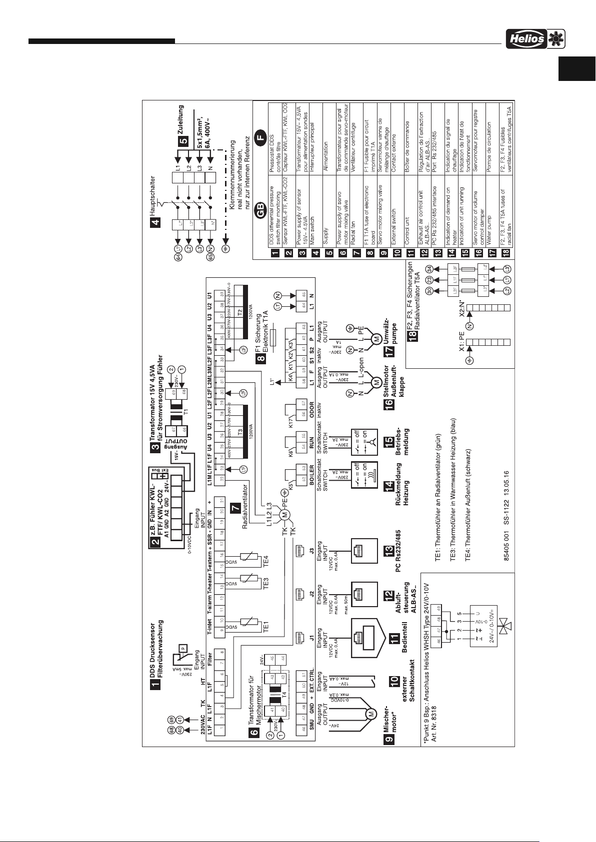
Installation and Operating Instructions
LB280/4/60/35 WW
A
Wiring diagram SS-1122
Fresh Air Boxes
UK
23

Installation and Operating Instructions
UK
LB280/4/60/35 EH
A
Fresh Air Boxes
Wiring diagram SS-1124
24

Installation and Operating Instructions
Notes:
Fresh Air Boxes
UK
25

Keep at hand for future reference! Print No. 91832/06.16
Service and Information
D HELIOS Ventilatoren GmbH + Co KG · Lupfenstraße 8 · 78056 VS-Schwenningen F HELIOS Ventilateurs · Le Carré des Aviateurs · 157 av. Charles Floquet · 93155 Le Blanc Mesnil Cedex
CH HELIOS Ventilatoren AG · Tannstrasse 4 · 8112 Otelfingen GB HELIOS Ventilation Systems Ltd. · 5 Crown Gate · Wyncolls Road · Severalls Industrial Park ·
A HELIOS Ventilatoren · Postfach 854 · Siemensstraße 15 · 6023 Innsbruck Colchester · Essex · CO4 9HZ
www.heliosventilatoren.de
 Loading...