

HELIOR ONLINE UNINTTERRUPTIBLE POWER SUPPLY, 4KVA, 6KVA Operational Manual

.
TYPE
- ONLINE
UNINTTERRUPTIBLE
POWER SUPPLY
.
POWER RANGE
-
4,000VA
-
6,000VA
English
OPERATIONAL MANUAL

Operational Manual
1
Contents
1
INTRODUCTION.............................................................................................2
2 SAFETY INSTRUCTION – CAUTION...........................................................3
2.1 IMPORTANT SAFETY INSTRUCTIONS..........................................3
2.2 Description of Commonly Used Symbols............................................. 4
3 SYSTEM DESCRIPTION ................................................................................5
3.1 Front Panel............................................................................................ 5
3.2 The LCD Display and Buttons Description .......................................... 6
Function.............................................................................................................6
Description................................................................................................................. 6
3.3 . ON/OFF Switch ...............................................................................6
3.4 Config Switch .......................................................................................7
3.5 Enter Switch:......................................................................................... 7
3.6 Input parameters (voltage & frequency) ............................................... 7
3.7 Output parameters (voltage & frequency)............................................. 8
3.8 Bypass mode.........................................................................................8
3.9 Economic mode.....................................................................................8
3.10 Inverter mode........................................................................................ 9
3.11 Warning and fault indicator .................................................................. 9
3.12 Battery capacity level..........................................................................10
3.13 Load percentage indicator...................................................................10
4 INSTALLATION............................................................................................ 16
4.1 Inspecting the Equipment....................................................................16
4.2 Placement............................................................................................16
4.3 Charging.............................................................................................. 16
4.4 Load Connection................................................................................. 16
4.5 Modem/Phone-line Connection ..........................................................16
4.6 DC Start Function...............................................................................16
4.7 Turn On/Off........................................................................................16
4.8 UPS Setup...........................................................................................16
4.9 Tower Setup........................................................................................17
4.9.1 TOWER CONFIGURATION SETUP.......................................17
4.9.2 RACK-MOUNT CONFIGURATION SETUP ..........................18
4.9.3 LCD display cover setup.............................................................18
4.9.4 Emergency Power Off(EPO) setup............................................. 19
4.9.5 Net/Tel Connection..................................................................... 19
5 BATTERY REPLACEMENT......................................................................... 20
6 COMMUNICATION PORT...........................................................................21
7 TROUBLE SHOOTING GUIDE.................................................................... 22
8 SPECIFICATION............................................................................................23
9 SOFTWARE INSTALLATI ON......................................................................25

Operational Manual
2
1 INTRODUCTION
This on line series UPS is an uninterruptible power supply incorporating double-conversion
technology and provides perfect pure sine wave output for load specifically designed for Servers.
Adopting the double-conversion principle, this advanced UPS system eliminates all mains power
disturbances. An internal rectifier converts the alternating current to direct current, and then the direct
current will be used for charging the batteries and powering the internal inverter. By converting the
DC voltage, the inverter generates a sinusoidal AC voltage which supplies the load without
interruption. All the peripheral devices are thus powered entirely by the mains power. However, In
the event of power failure, the maintenance-free batteries will power the whole system.
This manual covers the following Models of UPS. Please confirm if the model purchased is included
in the following list.
Model No. Type
4KVA Long backup time on line UPS
6KVA Long backup time on line UPS
Features:
♦ Pure sine wave output
♦ Rotatable LCD display design
♦ Tower / Rack multi-configuration for flexible installation
♦ Microprocessor control guarantees high reliability
♦ Adopting high frequency full bridge topology for high steady performance
♦ High input power factor correction
♦ Selectable various output range and operating mode
♦ Cold start function
♦ Built-in dry contact/RS-232/EPO communication port
♦ SNMP allows for web-based remote or monitoring management
♦ Optional AS400 relay card
♦ Enable to extend runtime with scalable external battery pack
♦ Overload, short-circuit, and overheat protection
♦ Hot-swappable battery design
♦ 19” rack mount kit available for all models

3
2 SAFETY INSTRUCTION – CAUTION
2.1 IMPORTANT SAFETY INSTRUCTIONS
SAVE THESE INSTRUCTIONS - This manual contains important instructions that should be
followed during installation and maintenance of the UPS and batteries.
WARNING: Do not attempt to repair and perform service on this UPS. This UPS contains
high voltages which could cause the risk of electrical shock. Even this UPS is
disconnected from the electrical outlet, the dangerous voltage may still be present through
the battery. All maintenance and battery replacement should be performed by qualified
service personnel only.
a) This UPS should be placed indoors with adequate airflow and free of
contamination. To install or operate it in a clean and indoor environment, free
from moisture, flammable liquids, and direct sunlight. Ambient temperature
range must be 0°C to 40°C (32°F to 104°F).
2) This UPS is designed for Commercial/Industrial use only. It is not intended for use with
life support application and other designated “life-critical” devices.
3) Do not remove the input power cord when this UPS is turned on. This removes the safety
ground from this UPS and the equipment connected to the UPS.
4) Turn off this UPS and disconnect input power cord before battery replacement.
5) The battery contains high short-circuit current. Replacing or servicing the battery
which should be performed and supervised by qualified service personnel
knowledgeable of batteries and required precautions.
a) Remove watches and jewelries
b) Use tools with insulated handles
c) Wear rubber gloves and boots.
d) Do not lay tools or metal parts on top of batteries.
e) Disconnect charging source prior to connecting or disconnecting battery terminals.
6) When replacing the batteries, use the appropriate replacement battery kits.
CAUTION! Replace with equal number and type of batteries is a MUST.
7) Do not open or mutilate the batteries. The released electrolyte is toxic and harmful to skin
and eyes.
8) Do not dispose of batteries into fire. Battery is extremely dangerous and explosive
under high temperature. Proper disposal of battery is required. Please refer to your
local laws and regulations about disposal requirements.
9) To reduce the risk of fire, use only No. 26 AWG or larger telecommunication line cord.
4
10) This UPS contains high voltages which may cause the risk of electric shock. Do not
remove the cover. There are no user replaceable parts inside of the UPS. Please
contact your local dealer or distributor for service.
11) During the installation of this equipment, it should be assured that the sum of the
leakage currents of the UPS, and the connected loads does not exceed 3.5mA.
12) Although disconnecting the UPS unit from the mains, hazardous voltage may still be
accessible through the supply from battery. The battery supply should be therefore
disconnected from the plus and minus pole of the battery when performing inside
maintenance or service of the unit.
13) The mains socket outlet that supp lies the UPS shall be installed nearby the UPS and
shall be accessible easily.
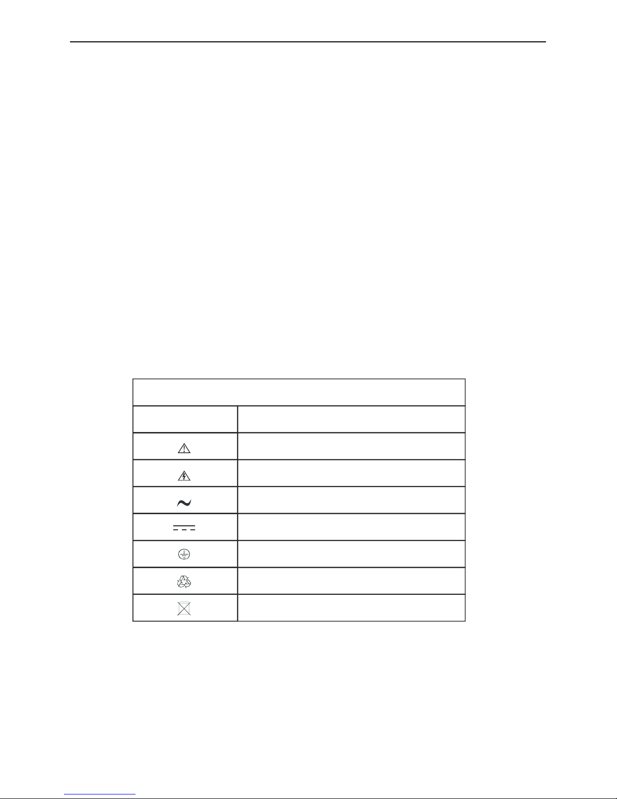
2.2 Description of Commonly Used Symbols
Some of all the following symbols may be used in this manual. It is advisable to familiarize
yourself with them and understand their means:
Sym b o l & De sc rip t io n
Sym b o l De sc rip t io n
Alert you t o pay special atte ntion
Caution of high voltage
Alternating c urrent source(AC)
Direct current s ourc e(DC)
Protective groun d
Re c yc le
Keep UPS in a clear area
5
3 SYSTEM DESCRIPTION
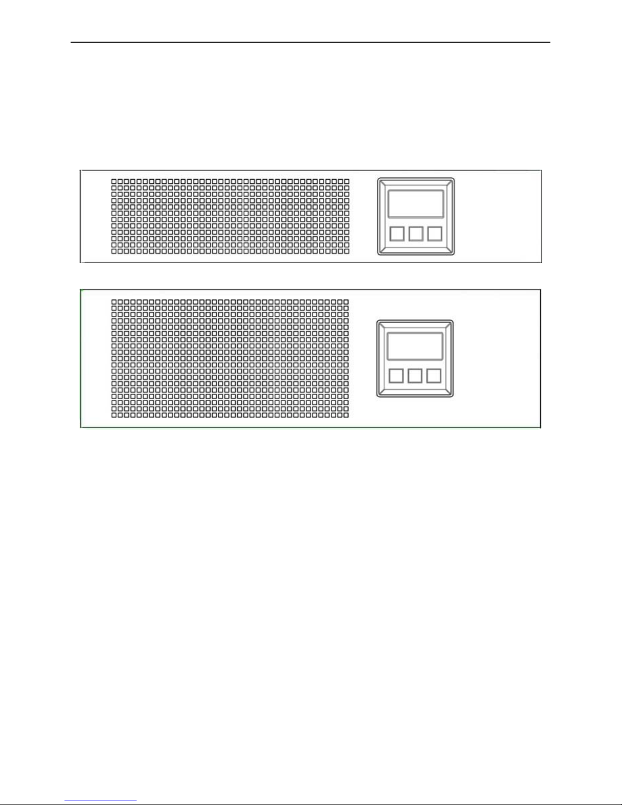
3.1 Front Panel
4K
6K
6
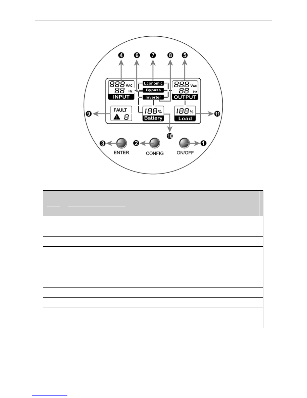
3.2 The LCD Display and Buttons Description
3.3 . ON/OFF Switch
z To turn on the UPS, press the “ON/OFF” button for more than three seconds.
z To turn off the UPS, press and hold the button until the UPS beep ceases.
No.
Function
Description
1 On/Off Switch For UPS on and off
2 Config. Switch For doing the UPS parameter configuration
3 Enter Switch To confirm the parameter setting
4 Input Information Input parameters (voltage & frequency)
5 Output Information Output parameters (voltage & frequency)
6 Bypass Indicator Operating in bypass mode
7 ECO Indicator Operating in economic mode
8 Inverter Indicator Operating in inverter mode
9 Warning Information Warning and fault indicators
10 Battery Information Battery capacity level
11 Load Information Load capacity level

7
3.4 Config Switch
Keeping this button pressed for three seconds, the LCD will enter the Configuration
Mode.
In the Configuration Mode, you can set ECO mode (i.e. economic mode) to be enabled
or disabled, Bypass mode to be enabled or disabled, and Generator input type enabled
or disabled as well. Additionally, the rated output voltage could also be changed within
220V/230V/240V.
After selecting the configuration mode, you must press the “Enter” button to confirm
the selection. Please refer to the Examples for Config Mode for more detailed
information.
Note:
1) If neither the “Config” button nor the “Enter” button pressed within 30 seconds, the
LCD system will exit from the Config Mode, and return to the original mode before the
configuration.
2) The explanation for the three modes:
a) Economic mode: The mode is for low power consumption but is recommend to
be selected only with high quality input power source.
b) Bypass mode: UPS supplies the load power from the utility directly.
c) Inverter mode (i.e. normal mode): The mode is for obtaining excellent output
quality but with higher power consumption. It is also the default setting mode.
3) Generator input type: If the mode is enabled, the UPS could accept wide range input
source, including frequency and waveform.
4) The default settings are Economic mode disabled, Bypass mode disabled, Generator
input type disabled, and the rated output voltage is at 230V.
5) Your configuration will be memorized by UPS, which means that the default setting
could be changed.
3.5 Enter Switch:
This button has three functions.
z To confirm the selected setting in Config mode accompanying with “Config” button.
z When AC utility power is available and the battery is full charged, it is possible to
perform self-test function by pressing and holding the button over five seconds.
z When UPS is not in configuration mode, keeping this button pressed less than five
seconds can disable or enable the alarm buzzer. Each time a new alarm event is
encountered, the alarm that will sound and press this button to turn off the alarm.
Note: Unable to disable alarm buzzer as below conditions: Low Battery, Overload, Fan
Failed, Fan Fault Time Out, and Over Temperature.
Note:
If any button is pressed, the back-light LCD will be on.
In Config mode, the back-light of the LCD will be always on.
If none of the button is touched for more than one minute, the back-light will be
off automatically.
When UPS is turned on, the back-light will be active for one minute.
3.6 Input parameters (voltage & frequency)
This part gives the information of the AC utility power, including input voltage and
frequency.
 Loading...