

Page 1
TOP HEADER
BOTTOM HEADER
SOLAR COLLECTOR
HEADER COUPLING
Z BARS BETWEEN
COLLECTOR AND ROOF TILE
CONTINUE
BOTTOM HEADER
EACH COLLECTOR SHALL BE CLAMPED @ 4 - PLACES
OF CONTRACTOR CHOICE RE: NOTES #2
GATOR CLAMPS RE: NOTES #2
Z BARS BETWEEN
COLLECTOR AND ROOF TILE
05
01*
*02
*02
*03
01
06
04
*10
01
DISCHARGE TO POOL
INTAKE FROM POOL
VACUUM RELIEF
01
*02
04
*11
05
*07
THERMOMETER
*03
04
05
SENSOR
BALL VALVE
06
*07
08
09
CHECK VALVE
3-WAY VALVE
WATER SENSOR
FILTER
08 09
*10
PUMP
AUXILLARY HEATER
*11
GENERAL NOTE: * COMPONENTS ARE OPTIONAL
*OPTIONAL COMPONENTS
MIRROR IMAGE PLUMBING LAYOUT ALLOWED – FEED & RETURN @ OPPOSITE DIAGONAL CORNERS
GATOR CLAMP RE: FIG 04
SOLAR COLLECTOR
ROOF TILE
FOAM ADHESIVE RE: NOTES #3
EXIST. UNDERLAYMENT
(2) TAPCONS RE: NOTES #2
EXIST. SHEETING
Z BAR RE: FIG 04
EXIST. TRUSS
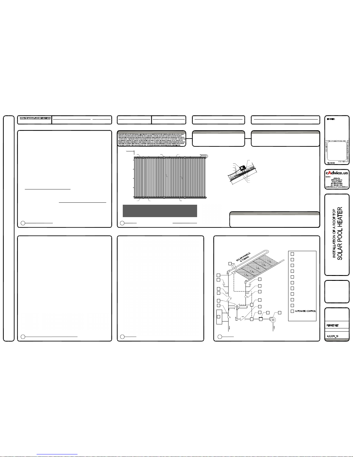
INSTALLATION OF A SOLAR POOL HEATING
SYSTEM WITH A ROOF TOP COLLECTOR
WIND LOAD: 200 D, RISK CATEGORY II
WINDLOAD RESITANCE DETERMINED BY
GATOR - HEADER CLAMPS
HELICOL SOLAR POOL HEATER COLLECTOR:
DIMENSIONS: 4'-0" X (8', 10' OR 12')
02
SCALE: 1/2" = 1'-0"
FIGURE 2
SHEET NO:
DATE:
REVISION NO./DATE:
SHEET NAME:
ROOF ANGLE:
COLLECTOR INSTALLATION
STANDARD FLUSH W/ ROOF
01
SCALE: N.T.S.
FIGURE 1
03
SCALE: N.T.S.
FIGURE 3
04
SCALE: NTS
USE OEM ATTACHMENT PARTS ONLY
NOTES FOR INSTALLATION OF HELIOCOL SPH (SOLAR POOL HEATER
) SYSTEM ON ROOFS USING LAGS, CONCRETE SCREWS, OR ADHESIVE FOAM:
THE DETAILS SPECIFIED ON THIS “PAPER” PLAN ARE CONSIDERED TO BE THE MINIMUM NEEDED BY AHJ (AUTHORITY HAVING JURISDICTION) AND
INSTALLERS. USERS ARE ENCOURAGED TO ACCESS EV (ELECTRONIC VERSION) OF THIS
PLANHTTP://GEZELMANPE.COM/GENERIC/0223S.AS_HELICOL_FL.PDF
ACTIVE HYPERLINKS ON EV PROVIDE EASY ACCESS TO INFORMATION. EV ALSO ALLOWS VIEWER TO STUDY THE PLAN AND OEM DETAILS AT A
MAGNIFICATION OF HIS CHOICE UP TO 6400%. IF A CONFLICT SHOULD OCCU R BETWEEN A DRAWING AND/OR SPECIFICATION HEREON AND AN
OEM DETAIL, OEM SHALL PREVAIL.
1.THESE DRAWINGS AND ENGINEERING ESTABLISH THE INSTALLATION REQUIREMENTS FOR HELIOCOL SOLAR POOL HEATING EQUIPMENT IN
ROOF PRESSURE ZONES 1 & 2 (PZ1 & PZ2) ON BUILDINGS IN FLORI DA 30 FEET OR LESS IN HEIGHT AND AT ROOF ANGLES FROM FLAT UP TO 45
DEGREES. INSTALLATIONS OUTSIDE THAT PERMISSIVE “WINDOW” REQUIRE SITE SPECIFIC ENGINEERING.
2.THERE ARE METHODOLOGIES EXP LAINED ON THIS PLAN AND IN THE OEM INSTALLATION MANUAL FOR ALL TYPICAL ROOF COVERINGS.
3.THERE SHALL BE NO TILT-UP. THE SPH COLLECTO RS SHALL REST DIRECTLY UPON AND SHALL BE MOUNTED PARALLEL WITH THE ROOF
SURFACE.
4.HELIOCOL SPH COLLECTORS ARE UNIQUE. UNLIKE OTHER SPH COLLECTO RS, HELIOCOL DOES NOT “FIGHT THE WIND”. HELIOCOL SPH
COLLECTORS ARE COMPOSED OF NUMEROUS PARALLEL INDIVIDUAL SOLAR COLLECTION WA TER TUBES WHICH ARE OVER-MOLDED INTO AN
UPPER AND LOWER HEADER. THE INDIVUAL TUBES ARE HELD IN ALIGNMENT BY SNAP-ON RIBS WHI CH ARE SPACED ABOUT 18-INCHES APART
PARALLEL WITH THE HEADERS AND PROVIDE AN AIR-GAP FOR PRESSURE EQUALIZATION BETWEEN THE ROOF COVERING AND THE SOLAR
COLLECTOR. AIR FLOWS AROUND THE INDIVIDUAL TUBES WITHOUT GREAT WIND RES ISTANCE. THIS PERFORMANCE CAN BE COMPARED TO
THE RELATIVELY HIGHER SURVIVABILITY OF PALM TREES WHICH BEND WITH HIGH WINDS AND SURVIVE HURRICANES WHILE NEIGHBORING
LIVE OAK AND OTHER MASSIVE TREES WHICH RESIST THE WIND ARE UPROOTED.
5.HELIOCOL COLLECTORS ARE CLAMPED TO THE RESPECTIVE ROOF WITH OEM “GATOR CLAMPS”. AS SHOWN IN THE DRAWING FIGURES. REFER
TO OEM INSTALLATION MANUAL FOR SPECIFICATIONS AND HAVE AN OEM INSTALLATION AVAILABLE ON JOBSITE FOR AHJ INSPECTOR
REFERENCE. THE UPLIFT RESISTANCE OF THE STANDARD METHOD OEM-RECOMMENDATION OF 4-GATOR CLAMPS PER HELICOL COLLECTOR
TWO EACH FOR UPPER & LOWER HEADERS IS ADEQUATE FOR WIND CONDITIONS TH RU VULT 160-MPH, EXPOSURE _ D, RISK CATEGORY II.
6.GREATER WIND FORCES REQUIRE THE USE OF A THIRD GATOR CLAMP EACH ON THE UPPER AND LOWER HEADERS.
7.GATOR CLAMPS ARE LAGGED THRU THE ROOF INTO STRUCTURAL FRAMING (MINIMUM 5/16-INCH DIAMETER, MINIMUM 3-INCH THREAD
EMBEDMENT) ON SHINGLE & MEMBRANE ROOFS.
8.TILE ROOFS REQUIRE THE USE OF A CO NTINUOUS Z-BAR UNDER EACH HEADER. THE Z-BARS ARE ATTACHED BY CONCRETE SCREW TO EACH
TILE CONTACTED. THE GATOR CLAMPS SCREW THRU THE Z-BARS. REFER TO OEM MANUAL. THE TILES AT EACH ANCHOR POINT SHALL BE
BONDED TO ROOF COVERING WITH A SOLID FSM (FOAM SET METHOD) BED OF DOW TILE BOND
HTTP://BUILDING.DOW.COM/NA/EN/PRODUCTS/ADHESIVES/TILEBOND.HTM
9.ENGINEER HAS EVALUATED THE INSTALLATION COMPONENTS AND HARDW ARE CURRENTLY PROVIDED AS HELICOL OEM INSTALLATION KITS
AND FOUND THEM TO MEET THE REQUIREMENTS OF THE FLORIDA BUILDING CODE. THERE SHALL BE NO SUBSTITUTION OF OTHER VENDOR
MATERIALS WITHOUT PRIOR APPROVAL OF ENGINEER THRU OEM.
10. PLUMBING SHALL BE PER FIGURE 1 (WITH OR WITHOUT THE DESIGNATED O PTIONAL ITEMS). FLORIDA PLUMBING CODE SHALL BE ADHERED
TO WITH PARTICULAR ATTENTION TO PIPE SUPPORT, PER FPC TABLE 308.5, THE ABS VALUE OF 4-FT SHALL BE TAKEN AS THE MAXIMUM FOR
HORIZONTAL AND 10-FT FOR VERTICAL SOLAR PIPING. CONTRACTOR SHALL INSTALL THE SYSTEM ACCORDING TO THE MANUFACTURER'S
WRITTEN INSTALLATION MANUAL.
11. INSTALL TAPCONS PER MANUFACTURER INSTRUCTIONS
HTTP://WWW.CONCRETESCREWS.COM/CONCRETE-SCREW-INSTALLATION.ASPX .
12. FOAM SET METHOD AVOIDS ANY PENETRATION OF THE ROOF COVERING BENEATH T HE TILE. WATERPROOFING OF OTHER ROOFS SHALL
RELY UPON A GENEROUS PUDDLE OF FLORIDA NOA/PCA APPROVED ROOFING SEALANT BETWEEN GATOR CLAMP AND ROOF COVERING. AS
AN ALTERNATE, WITH APPROVAL OF AHJ, CONTRACTOR MAY SUBSTITUTE A FLASHING DETAIL OF HIS PREFERENCE FROM NRCA ROOFING &
WATERPROOFING MANUAL OR OTHER RECOGNIZED PROFESSIONAL PUBLICATION.
13. CONTRACTORS, INSPECTORS, AHJS AND OTHERS HAVING QUESTIO NS MAY CONTACT ENGINEER DIRECTLY - OFFICE: 813 909 1956, E-MAIL:
[email protected].
ALLEN GEZELMAN
16502 HANNA RD.
LUTZ, FLORIDA 33549
PH. 813 650 7246
APPLICABLE CODE:
ASCE 7
COMPATIBLE WITH:
ASCE7-10
THIS IS A SINGLE
SHEET PLAN
COMPONENT AND CLADDING LOADING DIAGRAMS
DRAWN: SB CHECKED: AG
0223S.AS_HELICOL_FL.dwg
2010 FLORIDA BUILDING CODE
TESTING & CERTIFICATION NOTE:
SOLAR POOL HEATING COLLECTORS ARE REQUIRED TO BE TESTED, CERTIFIED AND LISTED BY THE
FLORIDA SOLAR ENERGY CENTER. THE COLLECTORS LISTED ON THIS PLAN COMPLY. THEIR FSEC
LISTINGS AND RATINGS MAY BE VIEWED ONLINE AT:
HTTP://WWW.FSEC.UCF.EDU/EN/INDUSTRY/TESTING/STCOLLECTORS/POOL_RATINGS/INDEX.HTM
COPYRIGHT & INTELLECTUAL PROPERTY NOTICE
• THIS PLAN SET IS COPY RIGHT PROTECTED AND CONTAINS I
NTELLECTUAL PROPERTY WHICH BELONGS TO ALLEN GEZELMAN PE.
• ACCESS IS GIVEN TO THE INFORMATION HEREON SOLELY FOR
THE PURPOSE OF COMPLETION OF THE PROJECT FOR WHICH IT IS INTENDED.
• NO OTHER USE MAY BE MADE OF THE INFORMATION, DRAWING
S, OR IDEAS HEREON WITHOUT THE EXPRESS, WRITTEN, PERMISSION OF ALLEN GEZELMAN PE
VALIDITY:
VOID WITHOUT RAISED OR ELECTRONIC SEAL, MAY NOT
BE USED FOR PLANS ON FILE, EVERY PERMIT PULLED
REQUIRES A SEALED ELECTRONIC PLAN OR SEALED
ORIGINAL PAPER COPY OF THIS PLAN
ENLARGED VIEWING:
HTTP://WWW.GEZELMANPE.COM/GENERIC/0223S.AS_HELICOL_FL.PDF
7/15/2012 2:56 PM
PZ 1 PZ 2 PZ 3
05
SCALE: N/A
ENGINEERING NOTES
EJCDC C-700
ALL AFFIDAVITS, DESIGNS, OPINIONS, CALCULATIONS & OTHER ENGINEERING SERVICES PROVIDED BY ALLEN GEZELMAN PE AND HIS
ASSOCIATES ON ANY AND ALL PROJECTS ARE SUBJECT TO THE PROVISIONS OF EJCDC C-700 (ENGINEERS JOINT CONSTRUCTION
DOCUMENT COMMITTEE - STANDARD GENERAL CONDITIONS OF THE CONSTRUCT ION CONTRACT) CURRENT AT THE TIME. THOSE
OBJECTING TO SAID EJCDC C-700 OR P ROVISIONS THEREOF ARE DIRECTED NOT TO USE THE A FFIDAVIT, DESIGN, OPINION,
CALCULATION OR OTHER ENGINEERING SERVICE OFFERED BY ALLEN GEZELMAN PE AND HIS ASSOCIATES ON THE PROJECT. EJCDC
C-700 MAY BE VIEWED AT: HTTP://GEZELMANPE.COM/REFERENCE/AG/C-700.PDF
NO PZ3 USE IN HVHZ
SOLAR UNIT (THERMAL OR PV) WIND FORCES
OEM:
ATTACHMENT DETAIL
SCALE 1-1/2" = 1'-0"
Z BAR
HELICOL COLLECTOR ON Z BAR GATOR CLAMP
HELICOL COLLECTOR HEAD ASSEMBLY
HELICOL GATOR CLAMP ASSEMBLY
SCALE: NTS
S5 CLAMP SYSTEM
http://www.heliocol.com/
Page 2

Residential Installation Manual
Swimming Pool Solar Heating System
Heliocol 2011
Revised 09/11
Page 3

Disclaimer:
Before attempting installation, read these instructions carefully. This manual contains easy to follow step-bystep procedures to properly install a Heliocol system. A little time spent understanding the system and its parts
will assure a successful, trouble-free installation. If you have any product or installation questions regarding this
system, contact your Heliocol Representative. When working on or around your roof or pool, please take care
to avoid hazards such as electrical wires and loose shingles or tiles. CAUTION! Safety comes rst!
It is important to recognize that this manual outlines the recommended installation methods and practices as
prescribed by the factory. It is designed to aid a seasoned contractor or novice do-it-yourself individual while
providing optimum protection for the products. It is not designed to override any local codes or ordinances.
Also, these are the minimal requirements; additional hardware or protection may be required in hazardous
environments or in areas subject to extremes of weather or microburst climate events. In those areas, the local expertise of the contractor may be relied upon in coordination with factory approval for special installation
considerations.
1
Page 4

Introduction
Welcome to the Heliocol Family
Heliocol Solar Collectors are manufactured utilizing state-of-the-art solar technology and the
most advanced production techniques. Heliocol collectors are sleek and simple, yet the patented over-molded design makes Heliocol durable enough to last a lifetime. However, a professional installation is very important to the overall success of a system. Installed properly, a
Heliocol System will be virtually maintenance free as it captures free, abundant and reliable
heat from the sun year after year. Whether you are a seasoned contractor or a homeowner
installing your own system, this manual will give you a great deal of valuable information.
Take time to read through this manual. It will guide you through the most efficient way to correctly install a Heliocol Solar System. By following this step by step guide, your system will
meet the installation standards recommended by the factory (see disclaimer on page 1). In
addition, because we’ve included techniques and tips gathered from experienced Heliocol
contractors throughout the country, using this installation guide will save you time and effort.
Table of Contents
Introduction
Getting Started
Collectors and Installation Kits
Parts List
Solar Collector Layout and Hydraulics
Connecting the Solar
Mounting the Solar Collectors on a Flat Roof
Assembly of Row Spacer Kits
Connecting the Solar Collectors to the Feed and Return Lines
Running the Feed and Return Lines from the Roof to Ground Level
How to Connect the Solar Collectors to the Existing Pool Filtration System
Pressure Testing the Heliocol Solar System
Operating and Check-Out Procedures
Installation Troubleshooting
Specications
2
3
5
6
7
12
13
14
15
16
18
20
21
22
24
2
Page 5

Getting Started
Before you begin your installation, here are a few important tips:
1. Caution – Safety Comes First
There is no substitute for safety. Always exercise extreme caution, care and good judgments when working
on or around a roof or pool area.
• Please take care to avoid hazards such as overhead electrical wires or loose shingles or roof
tiles.
• Be sure to secure ladders so they will not slip
or fall.
• Do not allow extension cords to lie in the pool
or in standing water.
• Wear shoes with proper tread to prevent slipping on the ladder or sloped roof areas.
• Disconnect all power to the pool equipment
when installing an automatic control system.
2. Always consult with the proper authorities or check
with your local building department for the permit requirements and codes applicable before you start your
job. Some installers prefer to use white pipe and ttings
on the roof, then paint the pipe and ttings a color that
closely matches the roof. The paint should be outdoor
rated and UV resistant. Painted pipes and ttings will
require additional maintenance. Most building departments require permits for installing solar pool heaters, a
practice strongly supported by Heliocol.
3. Before starting any work, determine the location of
your system and prepare a schematic drawing of the
installation area. Include the location of the feed and
return lines in this drawing. Roof areas often times look
bigger than they really are, so be sure to measure the
available area before making your schematic. Be sure
the planned placement of the collectors will allow the
collectors to drain when the pool pump shuts off.
4. To ensure a trouble-free system, don’t take short-
cuts. Whenever possible, collectors should be installed
so that they are accessible without being walked on.
Walking on the collectors should only take place when
absolutely necessary.(Never walk on collectors when
they are wet as they present a signicant slip hazard)
5. Familiarize yourself with all of the Heliocol com-
ponents and plumbing materials that you will need
to complete the installation. Here is a list of materials
most commonly used:
Pipe
Use pressure rated Schedule 40 PVC pipe. You may
prefer to use black, as opposed to white, PVC pipe on
the roof for aesthetic reasons. But because black PVC
can be difficult to nd, some installers have inquired
about the use of black ABS pipe instead. DO NOT USE
ABS PIPE. ABS pipe does not have the UV inhibitors
that PVC pipe has, causing ABS pipe to become brittle
and to crack after several years of exposure.
Pipe Fittings
Use PVC Schedule 40 pressure-rated ttings to match
your PVC pipe. Be sure NOT TO USE “plumbers” ttings or DWV ttings (drain, waste and vent). Because
black PVC ttings are difficult to nd, some installers
use spray paint to paint them black. Should you do so,
it is necessary to use a high-quality paint, preferably
with UV inhibitors. Do not use inexpensive “discount
store” brands as these will fade and peel very quickly.
PVC Cleaner and Cement
It is important to both CLEAN and CEMENT each PVC
joint. Use a quality, brand-name product and refer to
the product’s label for specic directions for use. Before
applying cement, be sure to clean each tting and pipe
end with the PVC Cleaner or “primer.” Soon after cleaning each part, apply ample cement rst to the tting
and then to the pipe end. Insert the pipe end into the
tting with a slight twisting motion until it seats to evenly
distribute the glue. Hold it in this position for 5 to 10
seconds to allow the joint to set up. Finally, wipe excess
cement off of the joint and pipe. When gluing CPVC
ttings to PVC pipe, such as the Heliocol 117 Pipe
Connector, it is necessary to use a good quality CPVC
all-purpose cement.
Note: Cold weather slows the set-up process for PVC
glue. If installing in colder climates, refer to the PVC
glue manufacturer’s charts for curing times.
Miscellaneous
Depending upon your specic job, you will need other
3
Page 6

plumbing items and materials such as: PVC valves, stainless steel lag bolts, polyurethane caulk, silicone spray,
pipe straps, black electrical wire ties, electrical wire nuts,
18ga-22ga sensor wire, 12ga-14ga electrical wire with
ground, Teon tape, concrete anchors and screws, electrical conduit, etc. Be sure to us quality products that will
withstand direct sunlight year after year.
Tools
Planning ahead and having the proper tools and materials on the job will make your installation much easier.
Typical tools and materials that are useful to have are:
• Flat head and Phillips head screwdrivers
• Power drill with bits, 5/16’ and 7/16”
sockets and drivers
• Pipe cutter or hacksaw
• Hammer
• Level
• Marking pen
• Silicone Lubricant
• Safety belts
• Lanyards
• Ropes
• Hard hats (where required)
• Garden hose
• Tape measure
• Channel lock pliers
• Caulking gun
• Ladder
• Chalk line
Note: While this manual explains how to install Heliocol Solar Collectors properly in typical situations, it cannot address all the unique or individual circumstances possible. If
you have any installation questions, contact your Heliocol Representative for assistance.
As the installing contractor, you are responsible for exercising good judgment when installing Heliocol Systems to protect the long term integrity of the collectors as well as the
mounting surfaces.
4
Page 7

Collectors and Installation Kits
Heliocol Components
There are three Heliocol components to each system—
collectors, collector kits and row kits. For each Heliocol
Collector that you install, you will need a collector kit.
For each row (bank) of collectors that you install, you
will need a row kit. To go around vents or pipes larger
than six inches (chimneys, skylights or changes in roof
elevations), you will need a row spacer kit. Refer to the
kit contents table below for more information regarding
these kits.
PK: Collector Kit
One of these kits is required for each collector. It
contains the parts necessary to connect the collectors
together and mount them on the installation surface.
RK: Row Kit
One of these kits is required for each row (bank) of collectors. It contains the parts necessary to connect the
collectors to the feed and return lines or collector header.
Kit Contents
RSK: Row Spacer Kit
One of these kits is required if you need to bypass a
vent pipe or obstacle larger than six inches. It is also
used to connect collectors that are on different roof levels or that are facing different directions into one row. It
contains the parts necessary to connect the collectors
to the PVC pipe between them.
Other Kits
PTK: Pressure Testing Kit
This kit gives you the components you need to pressure test the system once the installation is complete.
RTK: Repair Tool Kit
In the event a collector is damaged, this kit contains
everything needed to make a repair to a riser tube.
PK RSKRK PTK RTK
106A
110 Short
110 Long
113
117
140
141
142
130
133
GATOR CLAMP
GATOR CLAMP
Y
Other Installation Components Referred to in this Manual
110BTS
111
116
120
121A
124
125
1/4” x 4” STAINLESS STEEL LAG BOLT
“G” PIPE CLAMP
1/4” X 1-1/2” STAINLESS STEEL LAG BOLT
126
127
1790
3344
5210
1/4” X 2” STAINLESS STEEL LAG BOLT
5
Page 8
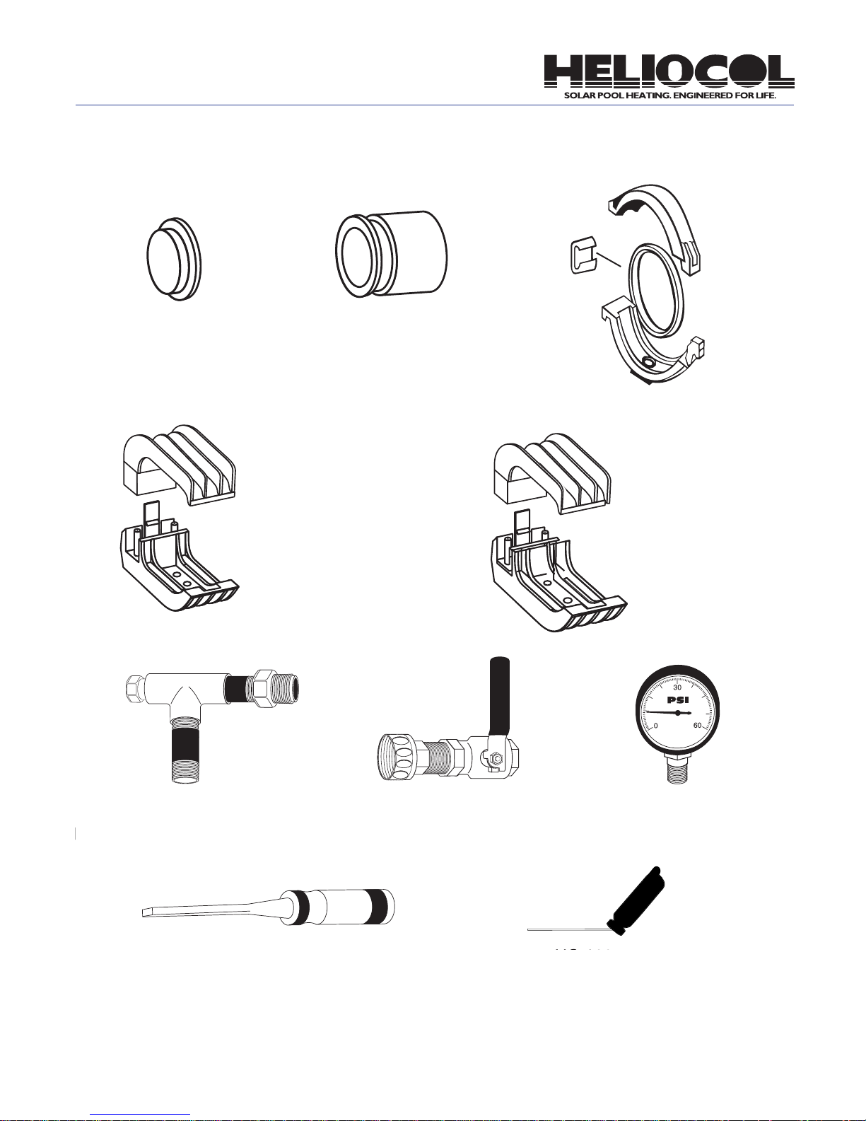
Parts List
106A
End Cap
Pipe Connector
100 Short
HC-0110 SHORT
ALLIGATOR CLAMP
Gator Clamp
117
113L
(Latch)
113B
(Bottom)
113T
(Top)
(Gasket)
113
Collector Clamp
100 Long
HC-0110 LONG
Gator Clamp
ALLIGATOR CLAMP
113G
142
Pressure Test “T” Assembly
133
1/4” Chisel
140
1/2” Ball Valve
141
Pressure Gauge
130
Pin Insert Tool
6
Page 9
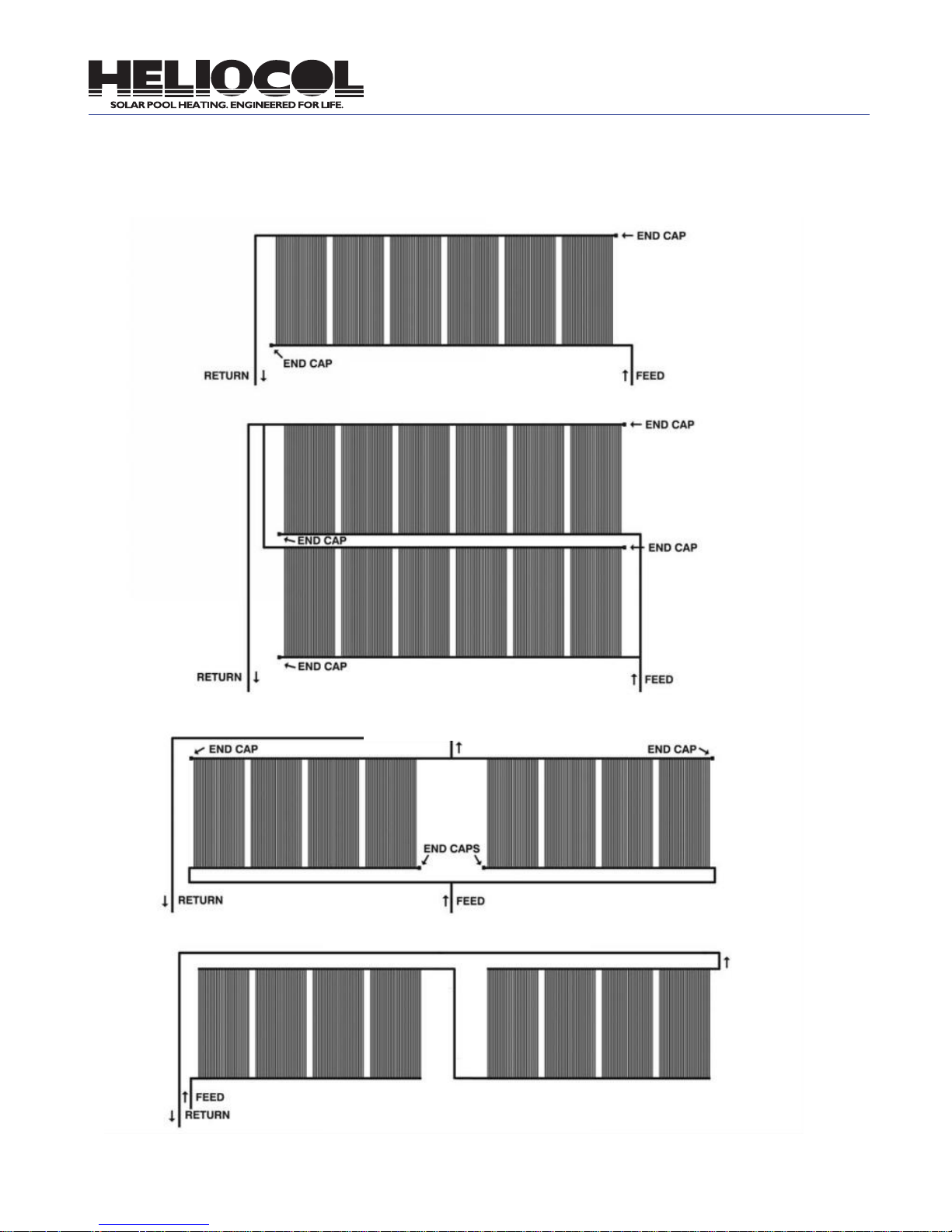
Solar Collector Layout and Hydraulics
Shown Below are the Most Common Solar Collector Installations
Fig. 1.1 - Single Row
Fig. 1.2 - Double Row
Fig. 1.3 - Single Row Spit Feed
Fig. 1.4 - Series Feed
Note: No more than two (2) arrays are allowed in series feed
7
and no more than eight (8) collectors are allowed in each array.
Page 10

Roof Orientation
Collector Congurations
(Northern Hemisphere)
Ideally, collectors should be located on a south-facing or
at roof, or on an elevated, ground-mounted rack facing
south. The next best orientation is west, then east. Finally, if arrangements are maid for proper draining, then
low-pitched or at. A collector should never be installed
on a north roof without a reverse rack in the northern
hemisphere.
Choosing the Right Size Collector
The roof space available to you will determine which
model collector to use. Since Heliocol manufactures collectors in ten different sizes, you have great exibility in
what you can design. The ten collector sizes are:
Model #
8
9.5
10.5
12.5
*15.5
30
38
40
50
*62
*Special Order
Whenever possible, the 50 should be used. This will:
• Reduce your total collector cost
• Reduce labor and installation material cost
• Reduce the length of the solar array
• Reduce the number of roof penetrations
• Produce a more attractive installation
However, unique roof designs may require a combination of different size collectors to best cover the roof
area.
Nominal Size
1’ x 8’
1’ x 9.5’
1’ x 10.5’
1’ x 12.5’
1’ x 15.5’
4’ x 8’
4’ x 9.5’
4’ x 10.5’
4’ x 12.5’
4’ x 15.5’
There are many ways to congure a solar array. The most
common and preferred is in one continuous row as in Fig.
1.1. There are, however, recommended limits to the number
of collectors that can be installed in this way to achieve
even ow throughout the array. The maximums are:
Model #
30
40
50
52
There are conditions which may exist, especially on existing pools, where the pump used for ltration is inadequate
to generate enough ow (GPM). Because of the unique
design of the Heliocol collector, arrays of collectors can be
plumbed in series (Fig. 1.4). Specic rules apply for series
feeding regarding the number of collectors in arrays and
drain-down considerations. Please contact a factory representative for assistance with design criteria.
Maximum Per Row
12
10
8
7
Pump Horsepower
The horsepower of your swimming pool ltration pump
must be adequate to supply the solar system with
enough water to provide the recommended ow rate
necessary for the collectors being installed. These recommended rates in gallons per minute (GPM) are:
Model #
10.5
12.5
30
40
50
62
For example; if you are installing ten 40 collectors, your
pump must be able to deliver 40 GPM to the solar array.
These ow rates may be exceeded by as much as 100%
without any detrimental impact on the performance of the
system. The existing pool recirculation pump is typically
adequate for recirculating the water through the solar
system. Generally, a 1 horsepower pump is sufficient for
a standard pool solar system unless there is an unusually
long pipe run a high roof or a large number of collectors.
If you are not sure what your pump ow rate is, consult
your Heliocol representative or pump manufacturer for
the pump’s ow characteristics.
Minimum Flow
1 GPM
1 GPM
3 GPM
4 GPM
5 GPM
6 GPM
8
Page 11

Plumbing
It is important that you use the proper size PVC pipe
for the size of the solar array. Using a pipe that is too
small will produce too much restriction to the water ow
and unnecessarily reduce the ow rate to the collectors.
Use the following as a guide:
Flow Rate
0 to 45 GPM
46 to 80 GPM
For larger ow rates, consult your Heliocol representative for the proper pipe size or alternative series plumbing techniques which will reduce the necessary ow
rates on larger systems.
Plumbing runs should be as short as possible and the
“hot return” pipe should have the shortest run to reduce
potential heat loss in this pipe. Pipes should be supported with pipe clamps or “G” pipe clamps at least
every four feet to prevent sagging. (Check the plumbing
code in the local jurisdiction.) The pipe clamp used on
pipe returns across a roof should be ½’ larger than the
pipe diameter to allow for expansion and contraction.
The pipe clamp used on vertical roof piping or piping
running up the sides of the building should be the same
size as the pipe diameter to prevent vibration and to
assure a professional-looking installation.
Since 90 degree elbow ttings produce a high restriction to ow, you will want to use a few as possible. Keep
this in mind when planning your plumbing runs. Their
use cannot be avoided, but with careful forethought,
you will use the least number possible. Occasionally,
the use of two 45 degree ttings will eliminate a 90, but
it is not necessary to always use them as this will run
up the expense of your materials.
Recommended Pipe Size
1 ½”
2”
Balanced Flow
When you have to split a solar system (Fig. 4.2 or Fig.
4.3, pg. 7) it is critical that the shown plumbing runs be
followed to assure equal water ow through both rows
of collectors. Since water will follow the path of least resistance, if one plumbing run is shorter than the other,
more water will ow through it than through longer one.
Keep this in mind if you design a collector layout differ-
ent than the examples. Your Heliocol representative can
also assist with this and explain the use of “balancing
valves” on larger systems.
If you are installing the solar collectors on a at roof or
at ground rack, the top (return) header of the collector should be a least 3” higher than the bottom (feed)
header to assure equal ow through all of the tubes of
all of the collectors. (See pg. 13) To achieve even distribution of water throughout the row of collectors, proper
ow rates and a little back pressure should be present.
Automatic Drain Down
The collectors and the PVC pipe should be installed
so the water will drain out of them when the pool pump
shuts off. This is especially important in areas of the
country where freezing conditions occur. (The Heliocol
solar pool collectors are warranted against internal
freezing when installed to allow for drain down.) To
allow for the water to drain a vacuum breaker, 121 is
installed on the solar feed line above the non-positive
3-way valve as shown on page 18, Fig. 15. (Non-positive
means that the valve allows for water to drain back
through the valve even when in the off position. If you
have a 3-way valve that is not non-positive, you can
make it so by drilling a 1/8” hole in the diverter.) If, as
a result of a unique roof design or adverse pool equipment location, it is not possible to achieve complete
automatic drain down, manual drain down valves should
be installed in appropriate places in the plumbing or at
the end of the bottom (feed) header. Instead of installing
an end cap 106A at the end of the header, you would
place a pipe connector 117, a 1 ½” slip x 1/2” threaded
PVC reducer bushing along with a ½” boiler drain 140.
These valves should be opened when shutting down the
system for the winter months or when freezing conditions are possible. On at roof installations, it might be
necessary to open the collector connections at the end
of the swimming season and manually lift the collectors
to evacuate all the uid from the system. Your Heliocol
representative can assist you with the parts necessary
for manual drain down installations.
9
Page 12
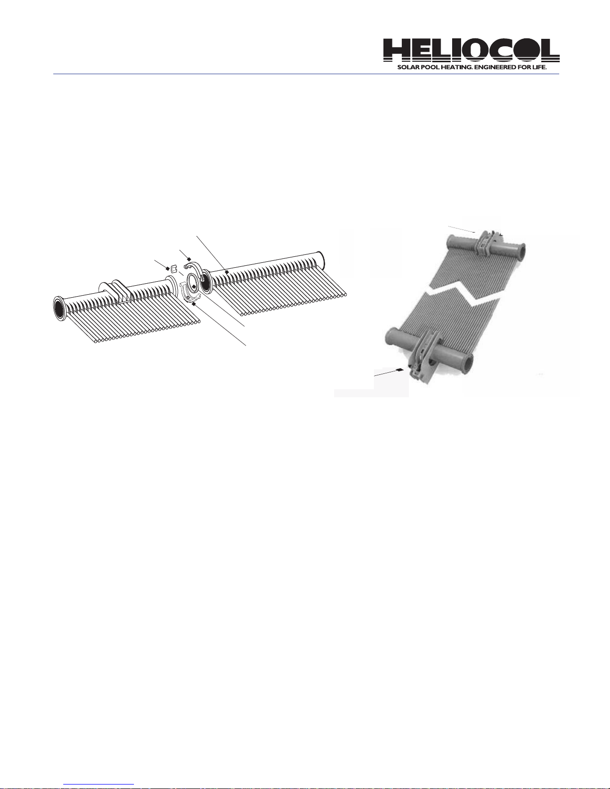
Mounting the Solar Collectors
Using Gator Clamps
The beauty of the Gator Clamp installation is its simplicity. It can be used on just about any type of roof or rack
installation.
Collector Header (Top)
113T Collector Clamp Top
113L Latch
113G Gasket
Fig. 2 113B Collector
Clamp Bottom
110 Long Gator Clamp
HC-110 Long Alligator Clamp
110 Short Gator Clamp
HC-110 Short Alligator Clamp
For rack systems, asphalt shingle roofs or tile roofs, follow these simple steps:
1. Snap a chalk line across the roof or rack where you
want the top edge of the collectors to be located. The
collectors should slope slightly down toward the feed
end of the array for proper drainage.
2. Locate the center of the rst truss/rafter you plan to
start from and drill a pilot hole where the rst lag screw
will penetrate the roof. After verifying the pilot hole
properly penetrated the structural wood truss or rafter,
measure and mark off the center-to-center truss dimensions for the rest of the trusses being used. This assumes trusses are located on 24” centers. Position the
rst clamp on the chalk line six (6) inches in from the
top corner of the rst collector. The rst collector will be
the one that is connected to the feed line at the bottom
header.
3. Subsequent clamps should be spaced out evenly
along the chalk line every 24”. Each clamp can be
located anywhere along the top header to match up to
the spacing of the roof rafters as long as there is a 2”
space between the edge of the clamp and the ribs (See
“ribs” in Fig. 14, pg. 17) on the collector header that exist
every one foot. This allows for horizontal expansion and
contraction. For barrel tile roofs, each clamp needs to
be positioned so that it is centered on the top ridge of a
tile, still as close to 24” centers as possible.
4. Since normal horizontal expansion and contraction of
an array of collectors takes place every day as collectors heat up and cool down, it is preferable to lock the
center of each array in place so that the expansion and
contraction takes place evenly to the left and right of this
center point. The center collector of an array may be
locked in place by locating the clamps on that collector
adjacent to the left and right of one of the header ribs.
(Fig. 4, pg. 11) these clamps should be attached using
two lag bolts as opposed to one. Do not use this procedure more than once on any array of collectors.
5. Apply ample sealant to the bottom of the clamp over
the hole or holes where the anchor bolt will attach (be
generous with sealant). (Fig. 5-A, pg. 11) Position the
bottom portion of the clamp perpendicular to the chalk
line with the lower hole being placed right on the chalk
line. Lag the clamp to the roof through the lower hole
using a 1/4” x 4” S.S. lag bolt. (Fig. 5-B, pg. 11) For barrel tile roofs, place four (4) 110BTS barrel tile spacers
underneath each clamp by inserting the four feet of the
barrel tile spacer into the four corners of the bottom of
the clamp. (Fig. 6, pg. 11)
6. The bottom of the clamp is designed to grip the roof’s
10
Page 13
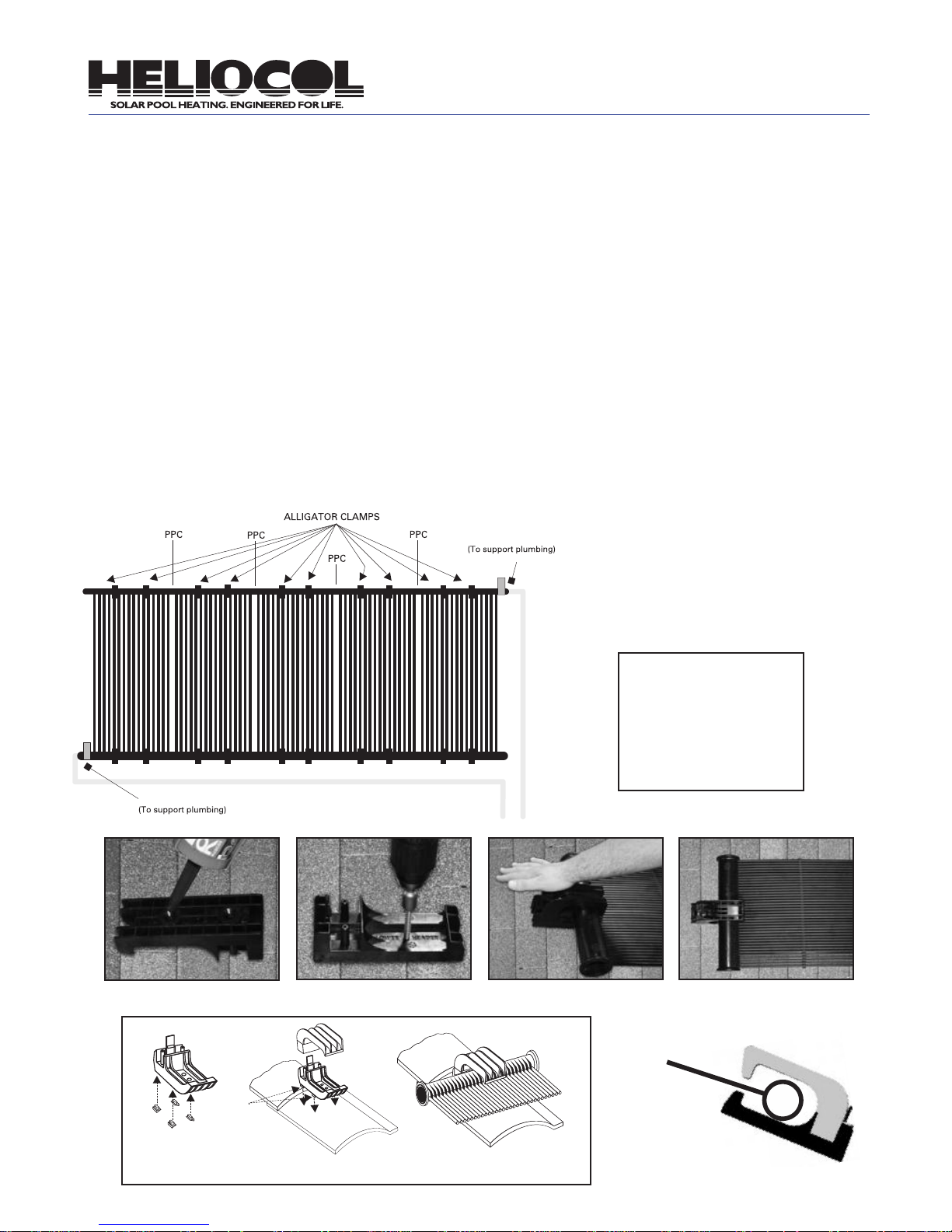
surface to avoid rotation back and forth; however, if the
roof surface is particularly hard or slick you can use an
additional lag bolt in either the top or center hole.
7. To ensure proper spacing, hang the top headers of
collectors in the bottom portion of the clamps attached
to the roof as you go. Once again, be sure clamps are
at least 2” away from each ridge along the header. (Fig.
5-D)
8. Once all clamps are properly lagged to the rack or
roof surface, and all the collectors are hung in place,
connect the top headers of each collector using 113
collector clamps. Snap the top portion of each clamp
over the collector header onto the bottom portion of
each clamp by pushing down rmly. (Fig. 5-C)
9. Install two (2) SS screws (#6 x ¾) to secure clamp
top to clamp bottom assembly.
10. Attach the bottom headers of the collectors with 113
collector clamps.
11. Locate and mount the clamps (2 each) along the
bottom header, aligned with the upper header clamps.
The bottom clamp should be installed allowing a large
gap on the top, allowing for contraction.
12. Attach feed and return lines following Heliocol’s
published guidelines.
13. The corners where the feed and return are located
should be fastened down by pipe straps that are also
supporting the pipe.
Note: Additional clamps are required for sur-
Pipe Strap
faces with a pitch of 10/12 or greater.
Note: To allow for vertical expansion and contraction, any clamps installed on the bottom
header must be positioned so that the header
is in the middle of the cradle. (Fig. 7)
Pipe Strap
Fig. 3
Fig. 5-A
110BTS
Gator Feet
11
110BTS
Gator Feet
Fig. 4
Fig. 5-B Fig. 5-C Fig. 5-D
Fig. 6
Fig. 7
Page 14

Connecting the Solar Collectors Together
In subsequent pages of this installation manual, you will
be instructed to connect Heliocol collectors together by
using the 113, plastic collector clamps. It is helpful to
familiarize yourself with this procedure ahead of time. To
assure a proper connection, follow these steps:
1. Lay two collectors next to one another with riser tube
spacer bars on the bottom. Lay an 113 plastic collector
clamp top, bottom, gasket and latch at both ends where
the headers meet. (Fig. 8-A)
2. Clean the groove of both headers.
3. Spray the gasket with a silicone spray only. (An easy
way to do this is to put all of the gaskets in one plastic
bag. Spray silicone into the plastic bag to lubricate all of
the gaskets at once.)
4. Insert gasket into the groove of one of the headers.
(Fig. 8-B) (Half in, half out.)
Fig. 8-A Fig. 8-B
t
5. Place the bottom half of the plastic collector clamp
(113) under the header end with the larger at portion
facing the roof.
6. Seat both headers together by inserting the gasket
into the opposite header groove and placing the ends of
both headers into the open space in the plastic collector
clamp bottom. (Fig. 8-C)
7. Interlock the top half of the plastic collector clamp
with the tab on the bottom half. Swing top half closed
over top of headers. Caution: Be sure to align top and
bottom so riser tubes pass through notch space in
interlocking end of collector clamp. (Fig. 8-G) Lock both
halves of the clamp together using the latch. (Note:
Slide large end of latch over small end of plastic collector clamp assembly. (Fig. 8-D and Fig. 8-E)
8. Use channel lock pliers to tighten the latch grip by
squeezing it with reasonable force until it seats ush or
even slightly farther so it cannot slide out of its position.
(Fig. 8-F)
9. Repeat the procedure to connect the bottom headers
of the collectors.
Fig. 8-C
Fig. 8-E Fig. 8-F
t
Notch Space
t
Fig. 8-D
Riser
Tube
Note: Now using four (4) Gator clamps,
neither the top or bottom header touches
the roof.
Fig. 8-G
12
Page 15

Mounting the Solar Collectors on a Flat Roof
Multi-Ply Flat Roof
Single-Ply Flat Roof
13
Asphalt Built Up Flat Roof
Page 16
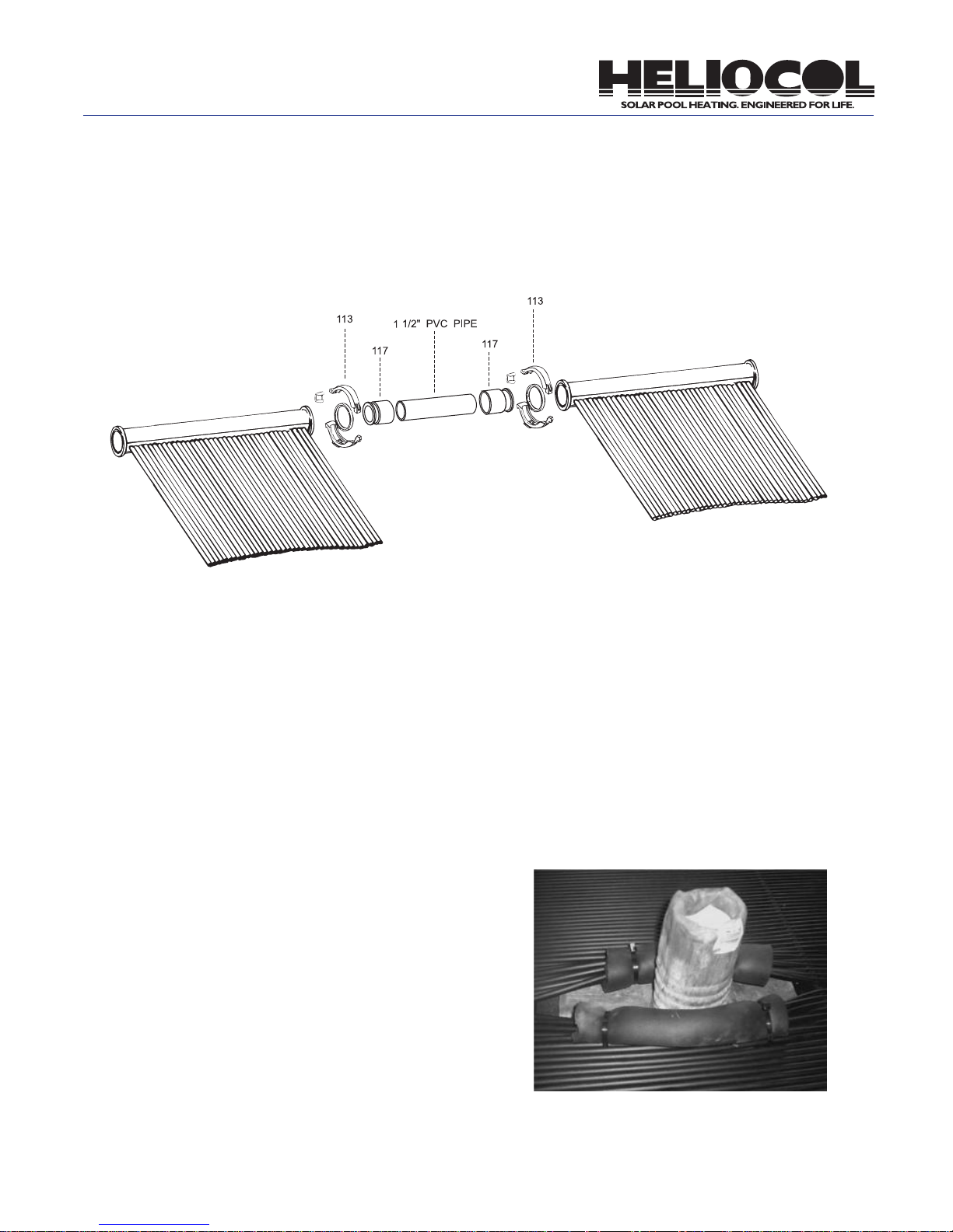
Assembly of Row Spacer Kits
When you need to install collectors over an obstruction
larger than six (6) inches wide, or if the obstruction is
less than one foot from a collector header, you’ll need a
row spacer kit to circumvent the obstruction.
Fig. 9
RSK
Connect the four (4) 117 pipe connectors to the headers of the collectors to be connected with a 113 plastic
collector clamp using the same procedures outlined in
the section on connecting solar collectors together on
page 12.
Cut two lengths of 1-1/2” PVC pipe long enough to cement the 117 pipe connectors on each collector to each
other.
Cement the PVC pipe to the pipe connectors as shown
in Fig. 9.
If the distance between the collectors is over 4 inches,
a 2-inch pipe clamp should be used on both pipes to
prevent sagging.
Note: When gluing the 117 CPVC pipe connectors, it is necessary to use good quality,
multi-purpose cement. The spacer bar may
need to be cut out of the way if it falls in
the obstruction’s path.
Warning: This should not be done between
the header and the rst spacer bar as it will
possibly pull the riser tube out of the header. The Heliocol warranty does not cover
leaks occurring from this type of incorrect
installation. A row spacer kit could be used
for this situation.
Flexible riser tubes are snapped out of the spacer bars
to go around small obstructions. The spacer bar may
need to be cut out of the way if it falls in the obstruction’s path.(Fig. 10)
Fig. 10
14
Page 17

Connecting the Solar Collectors
to the Feed and Return Lines
1. The feed line will be connected to the low end of the
bottom header which should be the corner farthest from
the pool pump. The return line will be connected to the
top header on the opposite end of the array. This gives
the heated pool water the shortest route back to the
pool.
2. The 106A end caps will be located on the corners of
the solar array opposite of the corners where the feed
line and return lines will be. Attach the 106A end caps
using the 113 plastic collector clamp as described on
page 12. (See Fig. 11)
3. Attach the 117 pipe connectors to the corners of the
array where the feed and return lines will be, using the
113 plastic collector clamp. (See Fig. 12)
4. The 117 pipe connector allows a 1 ½” PVC street
90 to be glued directly into the socket, or a 2” PVC 90
degree to be glued on the outside. All-purpose cement
should be used when attaching PVC ttings or pipe to
the pipe connectors to provide for a durable connection. A 90 degree PVC tting and vertical pipe run of at
least ve feet should always be attached to the return
line pipe connector to allow for lateral expansion and
contraction of the return line pipe run.
5. Connect the feed and return pipes using good
plumbing techniques.
Note: Be sure to align the top and bottom
of the clamp so that the riser tubes can
pass through the notch space in the interlocking end of the collector clamp. A clamp
that is improperly aligned can cause damage to the riser tubes (See Fig. 13).
Fi g . 11
15
Fig. 12
t
Notch Space
Fig. 13
Page 18

Running the Feed and Return Lines
from the Roof to Ground Level
Discussed here is the standard, most straightforward
way of running the PVC pipe from the feed and return
lines to the equipment pad. Some installations require
a more creative approach due to unique roof designs
or equipment pad locations. Whenever possible, however, the return line should have the shortest run and all
pipes should run slightly “downhill” to allow for automatic drain-down of the plumbing and solar array. As
discussed earlier, if this is not possible, manual drain
valves should be installed as needed.
If your equipment pad is against your house, you may
want to complete the necessary plumbing at the equipment pad before completing this portion of the installation. This allows you to know exactly where the pipes
should come down from the roof. If you will be trenching
from the equipment pad to the installation location, this
is not necessary.
1. Cement the appropriate size PVC 90 degree elbow
to the return line stub facing down toward the bottom
header. Repeat the process for the feed line header
stub and face the elbow down away from the array (see
Fig. 14, page 17)
Note: Whenever cementing, lay a rag on the
roof or rack under the joint to avoid dripping
cement on the mounting surface. Also, it is
a good idea to tape the cans of PVC cleaner
and PVC cement together. They are less
likely to tip over and spill this way.
2. Determine where the feed and return pipes will go
over the edge of the roof. If possible, this should be perpendicular to the exact points where they will fasten into
the existing system or into pipes coming from another
location. (See Fig. 15, pg. 18)
3. Measure the distance from the return elbow down to
the spot that you want to go, across the roof, to the point
established above. Be sure to include the depth of the
socket in the elbow in your measurement. Cut a piece of
PVC pipe to this length. Repeat this process for the feed
line.
the elbows.
5. Measure across the roof from these pipes to the
points established in step 3. Cut and de-burr pipes to
these lengths and assemble corner with 90 degree
elbows.
6. Continue this process around the edge of the roof
and down to the existing plumbing, using a level to keep
the pipes looking plumb and keeping pipes as short,
straight and tight to the building as possible.
7. Once you are satised with the plumbing arrangement, go back and cement the joints together using the
good plumbing techniques explained in the “Getting
Started” section.
8. Secure long pipe runs with pipe clamps or “G” pipe
clamps one size larger than the pipe diameter using
(116) #14 S.S. hex head screws and polyurethane caulk.
Secure vertical pipe runs on the side of buildings with
pipe clamps the same size as the pipe diameter using
screws and anchors as needed.
Note: All four corners of each row of collectors should be surely fastened to the roof.
The corners should already be secured
with the “G” pipe clamps or pipe straps on
the plumbing lines connected to the feed
and return lines. The top corner opposite
the return corner should already be secured by the collector mounting hardware.
Note: Be sure to support all of the weight
of the plumbing with “G” pipe clamps or
pipe straps. The mounting hardware is
not designed to support the weight of the
plumbing in addition to the weight of the
collectors.
4. If you are not experienced at cutting and tting pipe,
it is a good idea to assemble all pipe and ttings before
cementing them just in case you make an error. Clean
the burrs off these cut pipe lengths and insert them into
16
Page 19
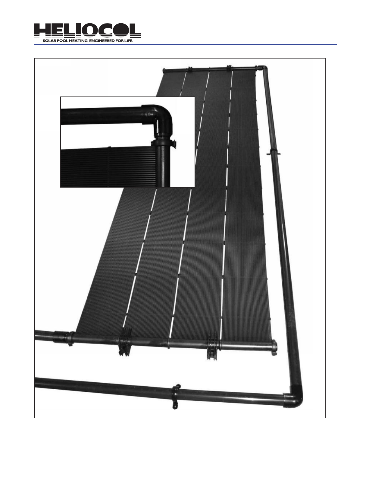
End Cap u
t Return Line
Feed Line q
17
Rib p
Fig. 14
End Cap
p
Page 20
How to Connect the Solar Collectors
to The Existing Pool Filtration System
(121)
WIRE TO ROOF SENSOR
(PTK)
(5210)
Manual
(5210)
(3344)
Wire to Optional
Motorized Actuator
(1790)
Optional Motorized Actuator
Fig. 15
18
Page 21

How to Connect the Solar Collectors
to The Existing Pool Filtration System
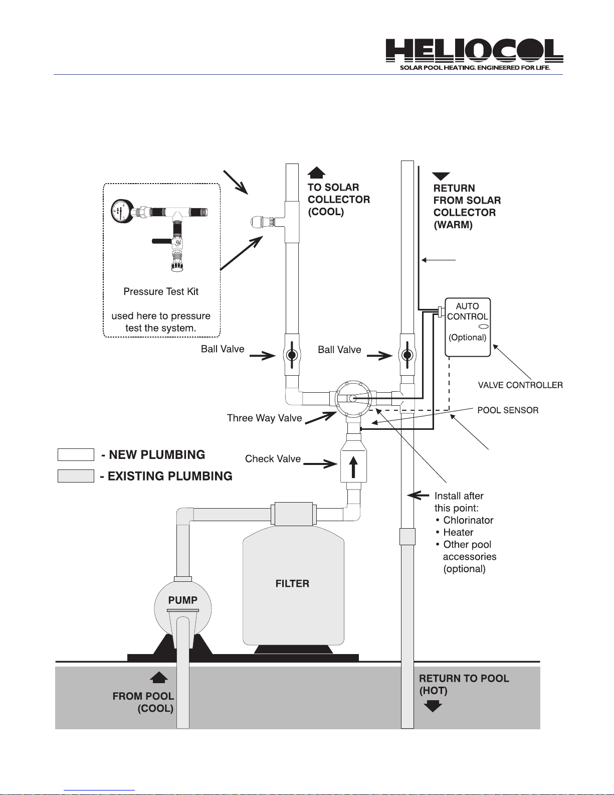
Fig. 15 on page 18 shows how a typical Heliocol solar
pool heating system is plumbed into existing pool
plumbing. This drawing may not be just like every system you encounter. The feed and return plumbing on a
solar system may be reversed, or it may have a different
type of lter, or it may have additional equipment such
as a chlorinator, pool cleaner, gas heater, etc. It may
also have a long run of plumbing from the pool equipment to the solar collectors.
Whether the system is like this or not, Fig. 15 will help
you understand the ow of water from the pool, through
the pump, lter, solar system and back to the pool.
Study the diagram and become familiar with the valves
needed to connect the solar collectors to the existing
plumbing.
Notice that the union check valve is plumbed in after
the lter. This prevents the lter from being backwashed
by the water draining down from the collectors when
the pump shuts off. The three-way valve either diverts
the water to the solar system or directly back to the
pool. This three-way valve should be a non-positive
valve. This enables the water in the solar system to
drain back to the pool when the pump shuts off. (If your
three-way valve is not non-positive you can make it so
by drilling a 1/8” hole in the diverter.) The ball valves
on the solar feed and return lines allow you to isolate
(completely shut off) the solar system. A check valve
can be substituted for the ball valve on the return pipe
side if desired.
1. Study the plumbing after the lter and decide where
you are going to install the union check valve and
the PVC tee tting (See Fig. 15). If you have auxiliary
equipment, you may need to re-plumb a portion of your
existing plumbing so this equipment is located after the
solar system as indicated in Fig. 15.
2. Cut the pipe after the lter where you have decided
to locate the union check valve and where your solar
return pipe will attach to your existing pool return line.
If your pool plumbing is 1-1/2” and you are running 2”
plumbing to your solar system, you should be using 2”
valves and piping for all of your new plumbing, so you
will need two (2) 2”x1-1/2” reducer bushings to adapt
your new 2” ttings to the existing 1-1/2” pipe.
3. As discussed earlier in this manual, it is a good idea
to assemble all pipe and ttings before cementing them
just in case you make an error. Install a union check
valve on the pipe coming out of the lter. Be sure that
the arrow showing ow direction is pointed away from
the lter.
4. The three-way valve will be installed next. It may
come right next to the check valve, or you may have to
use some pipe and ttings to locate it off of the main
line. As stated earlier, use as few 90 degree elbows as
possible.
5. Install the ball valve to the solar feed coming out of
the three-way valve.
6. Install the 121A vacuum breaker about 4 feet vertically above the lter, up the feed line, using a PVC tee
and red reducer bushing. Face the tee to the outside
as shown in Fig. 12.1. Wrap the threads of the vacuum
breaker with Teon tape and screw it into the ¾”
threaded reducer bushing.
7. Install the second ball valve or check valve to the
solar return line.
8. Now determine where to locate the PVC tee tting.
The tee may be located right next to the three-way
valve, or elsewhere, depending on your system. Connect the tee tting rst to the solar return line, then to
the three-way valve, and then to the pool return line.
9. Once you are satised with the plumbing arrangement, go back and cement together all joints that you
have not already cemented. Use good plumbing techniques and use caution not to drip glue or cleaner on
existing pool equipment, or inside any valves.
Note: Use pipe-clamps the same size as
the outside diameter of your plumbing ttings to secure the pipe and ttings tightly
to the wall.
For a truly professional-looking installation, take time
to clean the white PVC pipe. Use a clean rag and pour
PVC cleaner on it and then wipe the dirt and identication marks off the pipe. Do this on all exposed pipe.
This is also a good preparation if you plan on painting
the pipe to match the house color.
19
Page 22
If you are Installing
an Automatic System
The basic difference between the manual system just
outlined and an automatic system is the use of a motorized three-way valve. This three-way valve is operated
by a differential control which uses sensors to determine
if the solar system is warmer or cooler than the pool
water. In this way it can shut the solar system off when
cloudy conditions exist and thereby generate the opti-
mum performance from your solar investment. It also
allows you to select a maximum pool water temperature
so the solar system doesn’t overheat the pool. It accomplishes this by the use of a sensor on the roof and
a sensor installed into the pool plumbing. The directions
included with the automatic system components will
direct you in the installation of the control and sensors.
The three-way valve will be installed as described on
the previous page and observing the note above.
Pressure Testing the Heliocol Solar System
Pressure testing the entire solar system provides for a
trouble-free installation and takes only about fteen minutes. Any weak PVC glue joints, ttings or pipe, any improper collector clamp connections, will be evident while
the system is put under 40 to 50 pounds of pressure.
1. Allow ample time for all glue joints to dry completely.
Use this time to wrap up things and to clean up the job
site.
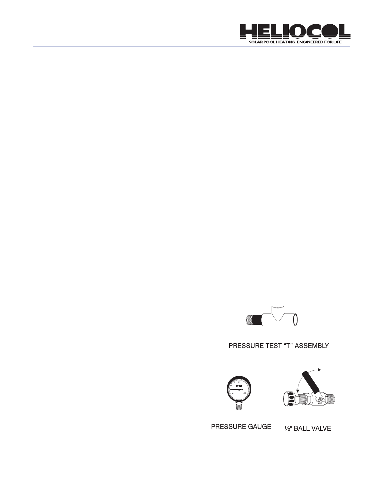
2. Wrap the threads of the 142 pressure test “T” Assembly, 140 ½” ball valve and 141 pressure gauge with Teflon tape. Temporarily replace the 121A vacuum breaker
with the 142 pressure test “T” assembly. Thread the 140
½” ball valve and pressure gauge into the pressure test
“T” assembly.
3. Attach a garden hose to the ½” ball valve. Make sure
the ½” ball valve is in the off position.
4. Turn the solar system on to allow the pool pump to
completely ll the solar system. (If the pool pump is not
operational, shut off the ball valve on the feed line and
use the garden hose to ll the system.)
5. Once the solar system is completely full of water, turn
off the pool pump or turn the three-way valve to by-pass
the solar system. Quickly turn off the ball valves on
both the feed and return lines.
6. Turn on the city water to the garden hose and open
the ½” ball valve on the pressure test “T” assembly until
the pressure gauge reads 40 to 50 PSI and then turn off
the ½” ball valve. Turn off the city water.
system for any leaks. A drop in pressure on the pressure
gauge indicates a leak in the system.
8. If there are leaks, open the ball valve on the return
line to relieve the pressure. Repair any leaks. Repeat
the pressure testing procedures as needed.
9. Return the system to normal when through with
pressure testing. Be sure to open both ball valves
and replace the pressure test “T” assembly with the
vacuum breaker.
(142)
(141)
(140)
7. With the system under pressure, check the whole
20
Page 23

Operating and Check-Out Procedures
Congratulations: If you carefully followed the steps in
this manual, you now have an efficient, professionallooking Heliocol solar pool heating system installation.
Final Visual Inspection:
Since you passed your pressure test at this point, lets
visually walk down the entire system and check the following items:
1. Verify that the check valves, control valves and
vacuum breakers are installed properly.
2. Verify that all plastic collector clamp clips are tight.
3. Verify that all lag bolts are secure and that adequate
sealant was used to prevent any roof leaks.
4. Be sure all collector riser tubes are snapped into
the spacer bars (except where they go around obstructions).
5. Be sure that collector riser tubes are NOT rubbing
on the roof surface between spacer bars. If they are,
adjust spacer bars as needed to prevent this or a hole
may develop in the riser tube.
6. Be certain that the system will automatically drain
down when the pump is shut off or that enough manual
drain valves have been included.
7. Verify that all pipe runs are properly supported with
pipe clamps.
6. When the solar system is running, you should notice:
• A slightly higher pressure reading on the pressure
gauge.
• At midday, if the sun is out, warmer water should
be coming into the pool. This water should be 3 to
5 degrees warmer than the pool temperature. Use
the back of your hand to better feel the difference in
water temperature.
• All the collectors should feel cool to the touch when
the sun is on them. (If they are not, see the troubleshooting section.)
7. During the cooler months of the year, it is essential
that the pool surface be covered at night with a “pool
blanket” to maintain a comfortable water temperature.
Low nighttime temperatures can lower the water temperature more than the solar can recover during the
day.
Turning the System Off
1. Turn the pool pump off.
2. Turn the three-way valve so the “closed” indicator
points toward the solar side of the valve.
3. If isolating the collectors, close the ball valves on the
feed and return lines after you are sure all the water
has drained out of the collectors and plumbing.
4. Turn the pool pump on to lter the pool as needed.
Turning the System On
1. Turn off the pool pump.
2. Turn the three-way valve so that the “closed” indicator points toward the pool side of the valve.
3. Be sure that the ball valves on the feed and return
lines are open.
4. Turn the pool pump on.
5. Set the pool pump timer, if used, so that the pump
will run when sun is shining on the solar collectors.
Usually 10:00 AM to 4:00 PM, but this will vary with
geographic location, time of year and the compass
location of the system.
21
That’s all there is to it. You have installed
a Heliocol solar pool heating system that
has been tested and proven worldwide for
quality and reliability. If you run into any
problems with your installation, or have
any future problems, call your Heliocol
representative or our corporate office at
800-79-SOLAR.
Page 24

Installation Troubleshooting
Trouble spots may arise during the initial
installation of your Heliocol solar pool
heater. Generally the primary cause of
problems, depending on its age, is the
existing pool/pump ltration system. Problems can also arise from installer error
or oversight. We are condent that your
system will work effectively and efficiently
when properly installed and matched to
your existing pool/pump lter system. This
troubleshooting guide is designed to help
your installation go smoothly and work
properly the rst day and every day thereafter.
There are Air Bubbles in
the Pool when the Solar
Heater is Operating
Diagnosis:
There may be air coming into the pump through an air
leak on the suction side of the pump due to the pump
working harder to move the water through the solar
system.
Pump Answers:
Be sure pump trap lid is on tight.
Check the “O” ring on the pump trap lid. Clean, lubricate or replace as needed.
If you have a suction type pool cleaner, remove it. If this
eliminates the air bubbles, use it only when the solar
system is off.
If you have a clear lid on the pump and can see air bubbles in the trap, use a garden hose to run water over the
lid and each joint individually to see if the air bubbles
will clear up. If there is not a clear lid, listen to pump
noise for a smoother operation. Repair any air leaks.
Diagnosis:
If the vacuum breaker is installed on the roof, there is
not enough water pressure in the solar system to keep
the vacuum relief valve closed so it is allowing air to be
drawn into the water as it ows by the valve.
Install Answers:
Be sure lter is clean. Backwash to reduce pressure.
Locate vacuum breaker on the feed line as shown on
page 18, Fig. 15, and put a solid end cap at the end of
the top header where the vacuum relief was located.
Using the (5210) ball valve on the return line, throttle
back the ow to produce more back pressure on the
system.
Some of the Solar
Collectors are Warm to the
Touch while Others are Cool
Diagnosis:
There is not equal ow through all of the collectors.
Warm collectors indicate low water ow.
Pump Answers:
Be sure the lter is clean. Backwash to reduce pressure.
The pump may not be providing enough water to the
solar system. Check water ow using a ow meter.
Increase pump horsepower to maintain recommended
ow. If there is a suction type cleaner in the pool, remove it. If this eliminates the problem, use it only when
the solar system is off.
Install Answers:
If the system is a single row array and there is adequate
ow, using the (5210) ball valve on the return line to
throttle the ow back to produce more back pressure
on the system. This will even out the ow through the
collectors. If the array contains more collectors than
the maximum recommended on page 8 of this manual,
change the array to a double row or single row split feed
as shown in Fig. 1.2 and Fig. 1.3 on pg 7.
If the system is a double row or single row split feed array and there is adequate ow, install a ball valve on the
return side of the set of collectors that are coolest to
throttle back the ow through these collectors and force
more water through the warmer collectors. If any section
of the array contains more collectors than the maximum
recommended on page 8 of this manual, make changes
as needed to correct this.
22
Page 25

Installation Troubleshooting Continued
Water Coming from the
Solar System is not as
Warm as it Should Be
Diagnosis:
The water is owing too fast through the collectors.
Install Answers:
Test water ow rate. Refer to the Collector Data for recommended ow on page 24. Adjust the three-way valve
to by-pass some of the water.
Diagnosis:
Seasonal normal operation
Answer:
In the cooler months of the year, or on cool, windy or
partly cloudy days, the temperature rise through the
collectors may only be 2 or 3 degrees. Use the back of
your hand to feel the water temperature difference at
the pool return inlet.
23
Page 26

Performance Rating
BTUs PER DAY
Certifying Organization 50 40 30 Performance Equations
Int’l Standard ORTECH 47,400 39,400 28,440
National Standard SRCC 47,400 39,400 28,440
Florida Standard 956 BTU’s/ft
Performance Note: Solar scientists agree that there are many variables to consider when properly sizing a system. Wind condition, micro climates, ow
rates, orientation and shading of the pool and/or collectors all affect the performance of your system. A BTU rating is just one of the many factors to consider.
2
956 BTU’s/ft
2
956 BTU’s/ft
2
.872 - 3.729 (Ti-TA) / I
X = 1.00-.0316(S) - .0104(S)
K
A
.872 - 3.729 (Ti-TA) / I
KAX = 1.00-.0316(S) - .0104(S)
.828 - 3.26 (Ti-TA) / I
KAX = 1.00 - .11(S)
2
2
Head Loss Per Flow Rate
Heliocol 50
Collector Rating Number
Thousands of BTU’s per day per collector
Category T(°F)
Water Temp.
Minus Air Temp
2,000 BTU/ft
A (-9) 98.74 78.07 57.49
B (+9) 64.13 44.01 23.96
C (+36) 22.91 7.64 0
D (+90) 0 0 0
E (+144) 0 0 0
Solar Insolation
2
1,500 BTU/ft21,000 BTU/ft
Collector Data
Collector Model 50 40 30 12.5 10
Size, Nominal 4’ x 12.5’ 4’ x 10.5’ 4’ x 8’ 1’ x 12.5’ 1’ x 10.5’
Width 47” (120 cm) 47” (120 cm) 47” (120 cm) 11.75” 11.75”
Length 152.1” (380 cm) 127” (323 cm) 91” (231cm) 151.5” 127”
2
Area (sq. ft) 50.0 (4.65 m
Manifold Diameter 2” (5.08 cm) 2” (5.08 cm) 2” (5.08 cm) 2” 2”
Weight (dry) 22 lbs (10 kg) 19 lbs (8.5 kg) 15 lbs (6.8 kg) 5.5 lbs 4.75 lbs
Volume Capacity 3.7 gal (14 L) 3.1 gal (12 L) 2.4 gal (9 L) .93 gal .78 gal
Workin gPressure 90 psi 90 psi 90 psi 90 psi 90 psi
Burst Pressure 270 psi 270 psi 270 psi 270 psi 270 psi
Recommended Flow 5 gpm 4 gpm 3 gpm 1.25 gpm 1 gpm
) 41.6 (3.88 m2) 30.0 (2.77 m2) 12.2 10.2
2
OG-100 Collector Approved
OG-300 System Approved
24
Page 27

Notes
25
Page 28

Notes
26
Page 29

Installation Manual
Heliocol is the rst and only solar pool collector in the world to achieve the
elite status of ISO 9001:2008 certication. Relatively few manufacturers have
the priviledge of placing the ISO 9001:2008 emblem on their products. Only
those companies performing at the highest levels in their industries can meet
the stringent requirements specied by this demanding international standard. The technical and engineering expertise of Heliocol and their relentless
pursuit of continuous product improvement have earned them the worldrenowned ISO 9001:2008 certication. Over the two-year process necessary
to gain certication, their customer service record, product failure rate and
engineering processes were all carefully scrutinized and found deserving of
ISO 9001:2008 certication.
The solar energy system described in this manual, when properly installed
and maintained, meets or exceeds the minimum standards established by
the Solar Rating and Certication Corporation (SRCC). This certication
does not imply endorsement or warranty of this product by the SRCC.
Heliocol solar pool collectors are NSF-50 certied. This certication ensures
that the water passing through the collectors will be free from unacceptable
levels of contaminates and will continue to perform effectively under the
intended use conditions.
 Loading...