

Page 1

BASIC INFORMATION
One of the most important factors in determining the way a
helicopter handles is the rotor head speed. Once you find a
rotor head speed you like, it is desirable to maintain that rotor
head speed at all times, during all maneuvers. However, there
are many outside factors affecting rotor
head speed such as
flight speed,
acceleration/deceleration, control inputs (rotor head
loading), wind, etc. The rotor head is constantly acted upon by
these and other forces which affect rotor head speed. Overrevving and overloading of the rotor head during maneuvers
results in decreased performance. During the time that the rotor
head has unloaded and rotor speed has increased, the
machine will become jumpy or too responsive. During the time
that the rotor head is overloaded and rotor head speed has
decreased, the machine will become sluggish and less
responsive. This never ending transition causes the pilot to wait
for the helicopter before giving the next control input. This
problem can be minimized with pitch and throttle curves, but it
is not possible to totally eliminate it—until now. The Rotor Head
Speed Governor operates the throttle servo to maintain a
constant rotor head speed at all times. This decreases the
amount of collective stick movements you must make, allowing
you to concentrate more on the other controls!
It is possible to select two rotor head speeds with the Governor.
Typically, a lower RPM is selected for hovering while a higher
RPM is selected for aerobatics. This can be done in flight by
adjusting a dial or flipping the rpm select switch on your
transmitter.
OPERATION
The governor is connected between the throttle servo and the
receiver (the same way a gyro is connected between the rudder
servo and the receiver). Three magnets are mounted to the
main gear in your helicopter. When spinning (at the same rpm
as the rotor head), the magnets pass by a sensor connected to
the CSU (constant speed unit—the little black box). The sensor
reads the rpm of the main gear and sends a signal through the
CSU to the throttle servo, which modulates the throttle servo as
required. The governor will operate between 900 rpm to 2,200
rpm. The pilot determines rotor speed by settings he programs
into the transmitter.
Please note that your governor will not:
❏ 1. Hold rotor head speed when your engine is not
correctly set
up (needle valve settings, exhaust system, etc.).
❏
2. Reach the full 2,200 rpm if your engine does not have
enough power.
DECIDE HOW YOU WILL TURN ON AND ADJUST
THE GOVERNOR
Now you know what the Rotor Speed Governor can do, but how
are you going to turn it on and adjust your rotor head rpm while
you are flying? Following are three methods we suggest for
using your governor.
Method A
Use a two position switch to switch between a lower rotor head
speed (for hovering) and a higher rotor head speed (for
aerobatics). This means that in addition to flipping the switch for
your different pitch curves (Normal, Idle up 1, Idle up 2), you
will also have to flip the rotor head speed switch to access your
other rotor head rpm. For example, when you go from your
normal pitch curve for hovering to your idle up 1 pitch curve for
aerobatics, in addition to flipping your idle up 1 switch, you will
also have to flip the governor switch to activate your higher
rotor head speed. The way you adjust the RPM for each switch
position (your two rpm ranges) is to change the ATV’s for both
ends of the switch. This means you can vary the rpm only on
either side of your “middle” rpm which will be around 1,400 rpm
(1478 rpm to be exact). In other words, the two rpm you can set
are only above 1,400 rpm (when your switch is in one position)
and below 1,400 rpm (when your switch is in the other
position). You cannot have rotor head speeds of say, 1,600 rpm
and 2,000 rpm because they are both on the same side of the
ATV range.
Method B
Use an adjustable dial or slider to change your rotor head
speed. This allows infinite adjustment of your rotor head speed
(between 900 and 2,200 rpm) in any of your pitch curves, at
any time. But, you will have to manually adjust the dial while
you are flying. This might be a good method for starting out
while you get the feel for how your governor operates. With this
method, you can also turn the governor off at any time (instead
of when your throttle stick drops below a preset point when you
land, as in method A). For example, once you have established
a hover and set your hover rpm with the dial, use the dial to
increase your head speed when you go into your aerobatic
pitch curve. Similarly, when you switch back into your hover
pitch curve, adjust the dial to lower your head speed.
Method C
Use your pitch curve switch (Normal, Idle up 1, Idle up 2) to
access your pitch curves and simultaneously activate
corresponding rotor head rpm preset by the governor. This
requires a computer radio with programmable mixing where
you can alter the center point of the channel that determines
your rotor head rpm (to preset the rpm for each of your
conditions—Normal, Idle up 1, Idle up 2). Use the “offset”
mixing type instead of linear mixing type.
Rotor Head Speed Governor
INSTRUCTIONS
Congratulations and thank you for purchasing the Heli-Max
Rotor Head Speed Governor. The Governor is ideal for
expert aerobatic pilots who demand a constant rotor head
speed in order to maximize their helicopter’s performance,
and for novice pilots who wish to simplify pre-flight setup
(actually, experts can realize the benefits of simplified setup
too!) In other words, the Rotor Head Speed Governor is for
everybody!
Page 2
Before you test and install your governor, if possible, you
should test fly and set up your helicopter to perform the way
you like.
HOOKUP THE GOVERNOR
Your governor comes equipped with Futaba®brand “J” style
connectors. If you own a Futaba radio system, proceed to step
1 below. If you own another brand of radio, you may have to
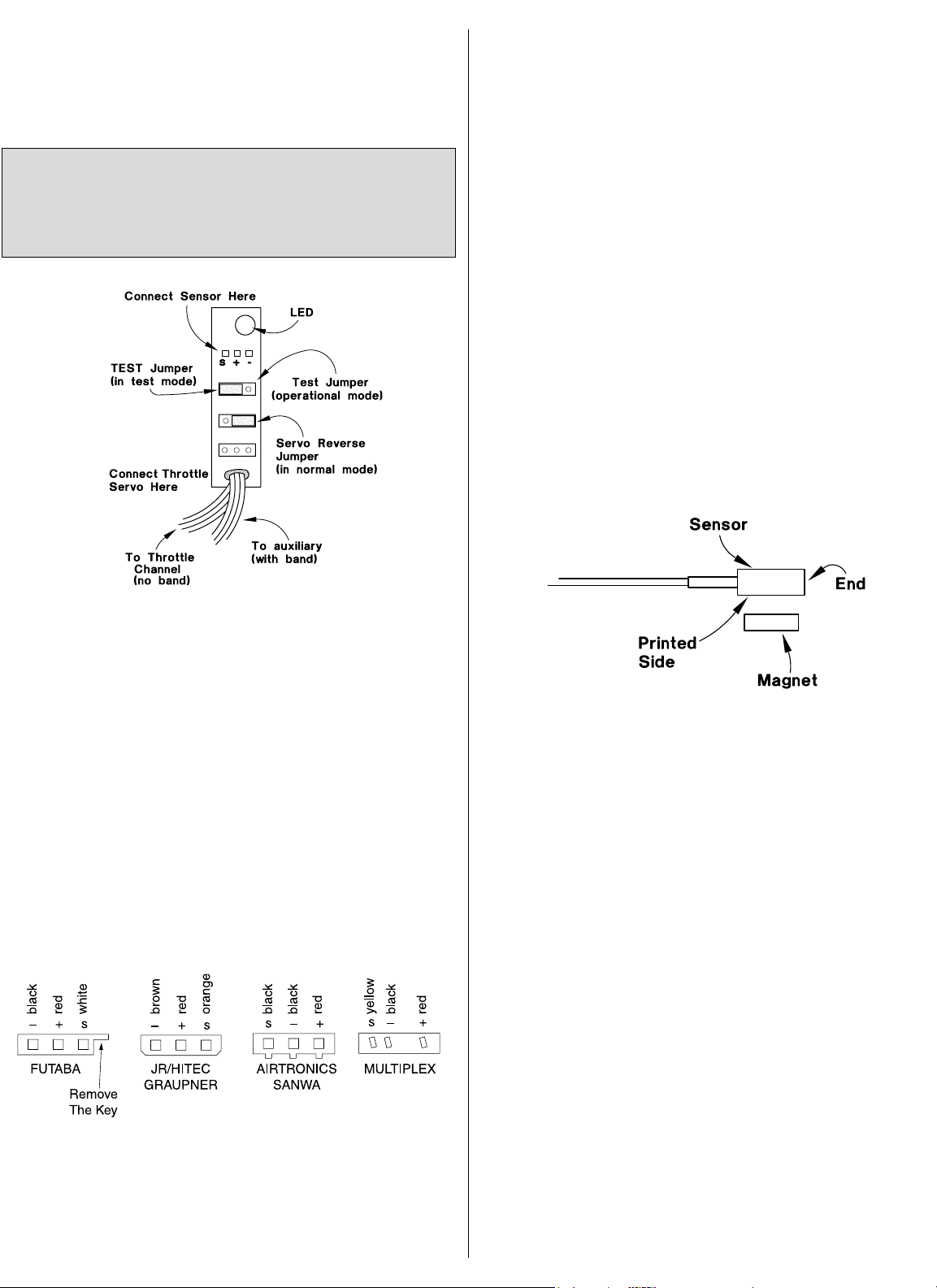
modify the connectors on your governor. See the diagram
below for proper polarities for major radio brand connectors.
Usually, all that is required is to carefully remove the key on the
connectors on the governor with a utility knife so they will fit into
the slot on your receiver. If you’ve modified your connectors,
make certain the wiring order on your governor connectors
and the servo connectors is the same as the wiring order on
the Futaba connector.
Study the diagram carefully. The positive (+) wire is the center,
the negative (-) wire is on the side opposite of the key on the
connector and signal (S) is on the side of the connector nearest
the key. WARNING! Failure to match polarities on any
connector
may damage your gyro and will void your warranty.
❏
1. Connect your throttle servo to the bottom output of the
governor.
❏
2. Determine whether you will use a dial to vary your rotor
rpm or a two position switch to switch between a preset high
and low rpm. Connect the lead with a band from the governor
to the channel on your receiver that is operated by the switch or
dial you selected to control rotor rpm (usually Auxiliary 1).
Some pilots with advanced computer radios may choose to use
their programmable mixing and flight conditions to mix preset
rotor rpm with their pitch curves (Idle up 1, Idle up 2). When
different pitch curves are switched on (Idle up 1, Idle up 2), the
preset rotor rpm will be selected without having to adjust an
additional dial or switch.
❏
3. Connect the lead from the governor without the band to
the throttle servo output on your receiver.
❏
4. Connect the governor’s sensor lead to the top output of
the governor.
SET UP AND TEST PROGRAM
Determine The Active Side Of The Magnets
❏
1. Place the test jumper in the test mode on the governor
(refer to the previous diagram).
❏
2. Turn on your transmitter, then your receiver.
❏
3. Place one of the magnets on your workbench. Pass the
sensor over the magnet within a distance of 2mm or less. Note
that the printed side of the sensor, not the end, reads the magnet.
❏ A. If the LED on the governor glows, use a felt tip pen to
mark
the upward facing side of the magnet as “active” (mark an “A”).
❏
B. If the LED on the governor does not glow, flip the magnet
over and try again. When the LED glows mark that side of the
magnet as active.
❏
4. Determine and mark the active side of the remaining two
magnets.
Now you’re ready to begin the setup and test program.
Set Up Your Transmitter
❏
1. If your radio has a “hovering throttle trim” (an adjustable
trim operated by a dial that is used to adjust throttle position at
hover only), deactivate or inhibit the trim. This is not to be
confused with your regular throttle trim.
❏
2. Turn your ATV’s at both ends of your throttle servo to
100% (when instructed to do so, you will have to adjust your
throttle linkage mechanically because the ATV’s must be set at
100% for your governor to operate correctly).
Do not mount the governor in your helicopter until instructed
to do so. We recommend setting the governor up on the
bench before you mount it in your helicopter. This will make it
easier to perform the test procedures and give you a better
understanding of how the governor works.
2
Page 3

Set Up And Test The Governor
❏
1. If you haven’t already done so, turn off your Tx and Rx.
Now, turn on your Tx, then the Rx.
❏
2A. If you are using an adjustable dial on your transmitter to
adjust the rotor rpm, turn the dial to the position where the rpm
will be minimum (counter clockwise).
❏
2B. If you are using a two position switch to select between a
high and a low rpm, flip the switch to the position that will be
used for the lower of the two rpm.
❏
3. Pass the sensor over one of the magnets three times. The
LED on the governor will glow each time. If the LED does not
glow, you have your magnet upside down. Flip the magnet
over, reset your radio, and return to step 1.
❏
4. Pass the sensor over the magnet a 4th time. The throttle
servo should move the carburetor to “idle” position. If the
throttle servo moves to full throttle, reverse the direction of your
servo using the reverse jumper on the governor. Turn your Rx
switch off, move the reverse jumper to the servo reverse
position, then reset the governor by turning it back on and
passing the sensor over the magnet 4 times. On the 4th time
the throttle servo should move to idle.
❏
5. Pass the sensor over the magnet a 5th time. The throttle
servo will move the carburetor to full throttle.
❏
6. Pass the sensor over the magnet a 6th time. The throttle
servo will move the carburetor to engine off.
❏
7. Repeating steps 1 through 6 as many times as necessary,
adjust your throttle linkage (do not use your ATV’s) so your
carburetor is fully open and fully closed when the governor
moves the throttle servo after passing the sensor over the
magnet the 5th and 6th time.
❏
8A. If you are using a dial to adjust the rpm, turn the dial to
its maximum position.
❏
8B. If you are using a switch to select a high and low rpm,
flip the switch to the position that will provide the higher of the
two rpm.
❏
9. Pass the sensor over the magnet a 7th time. If the LED
glows, reverse the channel in your transmitter that operates the
dial or switch you are using to adjust the rpm, then reset the
governor. When you get to step 9 and the LED flashes, go to
the next step.
❏
10A. If you are using a dial to adjust the rpm, turn the dial to
its minimum position.
❏
10B. If you are using a switch to switch between high and
low rpm, flip the switch to the position that will provide the low
rpm. The LED will glow.
❏
11. Turn the dial or your rpm select switch to the high rpm
setting. The LED will go out. At this point the governor is
activated and will maintain constant rotor rpm.
❏
12. Turn the dial or your rpm select switch to the low rpm
setting. The LED will glow. Now the governor is deactivated.
❏
13A. If you are using a dial, slowly increase the dial until the
LED goes out. At the point when the LED goes out, the
governor is activated. From this point on, rotor rpm will increase
as you turn up the dial.
❏
13B. Decrease the ATV on the side of the rpm select switch
that controls the lower of the two rpm positions until the LED
goes out. Note the ATV percentage. At this point the governor is
active and is set at the lowest possible rpm you can use
(900 rpm).
❏
14A. Slowly decrease the dial until the LED glows. The
governor is now inactive.
❏
14B. Slowly increase the same ATV you adjusted in step
13B until the LED glows. The governor is now inactive. When
it’s time to fly your helicopter and set the hovering rpm, set your
helicopter on the ground and adjust the ATV until you reach the
rpm you desire.
❏
15. Move your throttle stick to full throttle. Pass the sensor
over the magnet an 8th time. The LED should flash.
❏
16. Move the throttle stick to idle. The LED will glow. Now
the governor is inactive.
❏
17. Move the throttle stick back to full throttle. While you do
this, note the position of the throttle stick when the LED goes
off. This is the point at which the governor “turns on” and
cannot be adjusted.
❏
18. Now that the governor is set up, activate your other pitch
curves (Idle up 1, Idle up 2). Lower the throttle stick. Make sure
the LED remains off so the governor will not turn off when you
lower the throttle stick while performing aerobatics (or hovering
inverted).
❏
19. If the LED remains off, your governor is set up correctly
and you are finished. If the LED glows when you lower the
throttle stick while you are in your aerobatic pitch curves (Idle
up 1, Idle up 2), raise your throttle curves so the LED remains
off. Now you are finished setting up the governor.
You must adjust your linkage mechanically because the
throttle servo receives its signal from the governor, not your
transmitter. This is a fail safe feature. Do not use your ATV’s
to adjust the throttle lever settings.
In the flow chart, whenever you see the term “Reset your
governor,” it means you should turn off your receiver, return
to step 1 and follow the flow chart until you return to the step
that instructed you to reset your governor.
Refer to the flow chart to help you through the steps of
setting up your governor. The steps in the flow chart
correspond to the steps in the following instructions.
3
Page 4

Mount The Magnets And Sensor
❏
1. Determine where you will mount the magnets and sensor.
The magnets must be mounted where they will turn the same
rpm as the main rotor. We recommend you mount them to the
main gear.
❏
2. Use the template included to accurately mark your main
gear where each magnet will be positioned. Make sure you
count the same number of gradations along each 120° line so
the magnets are aligned. This is important for the sensor to
read them correctly and for balance!
❏
3. Mount the magnets in or on the main gear (with the active
side facing the sensor). They must pass within 2mm of the
sensor. You may mount the magnets to the surface of the gear
with silicone cement, epoxy or CA. For the most security, we
recommend drilling a 3/16" diameter shallow cavity or a hole all
the way through the gear to hold the magnets.
❏
4. Mount the sensor. If possible, mount it directly to the
frame of the helicopter, or fashion a mount from thin plastic or
aluminum. Mount the sensor mount to the frame of your
helicopter where the sensor will be within 2mm or less of the
magnets when they pass.
❏
5. Make certain the sensor and none of the cords can
interfere or become entangled in the mechanics of the
helicopter.
TEST FLYING
Start your engine with the throttle stick at idle and your rpm dial
or switch on the low rpm setting. The governor will not be
activated until the throttle stick reaches the required position
(noted in step 17 under Set Up And Test The Governor) and
you advance the rpm dial (or adjust the ATV if you are using a
two position switch).
When you are ready to lift off, advance the throttle to begin the
rotor head turning, then turn on the governor by adjusting the
dial (or adjusting the ATV) until the desired rotor rpm is
reached. There will be a slight delay when you change the rpm.
Important: Be certain the jumpers are secure on the governor
unit. If the servo reverse jumper becomes disconnected, the
governor will switch off.
Initially, your helicopter will feel different. But, after you get the
feel for the new setup you will wonder how you did without it!
You can get the maximum from your rotor speed governor (and
your helicopter) if you experiment with different rotor rpm. This
way, you can match your helicopter to your engine. Once you
have mastered the setup of your rotor speed governor, your
flying sessions will become more relaxed. Gone will be the
days of programming rotor blade pitch and throttle curves! This
leaves you to the most important task at hand—flying!
TECHNICAL DATA
Power supply: 3-9 Volt DC
Consumption: 7mA
Size: 2.2 x 1.4 x 0.4" (56 x 37 x 10.5mm)
Weight: 0.14 oz (4g)
Operational range: approx. 900 rpm to approx. 2,200 rpm
with included three magnets (approx. 650
rpm to approx. 1530 rpm with four
magnets)
ONE YEAR WARRANTY STATEMENT
*USA and Canada Only
Heli-Max warrants this product from defects in materials and
workmanship for a period of one year from the date of
purchase.
During that period, Heli-Max will, at its option, repair or replace
without service charge any product deemed defective due to
those causes. You will be required to provide proof of purchase
(invoice or receipt). This warranty does not cover damage
caused by abuse, misuse, alteration or accident. If there is
damage stemming from these causes within the stated
warranty period, Heli-Max will, at its option, repair or replace it
for a service charge not greater than 50% of its then current
retail list price. Be sure to include your daytime telephone
number in case we need to contact you about your repair. This
warranty gives you specific rights. You may have other rights,
which vary from state to state.
For service on your Heli-Max product, warranty or nonwarranty, send it post paid and insured to:
HOBBY SERVICES
1610 Interstate Drive
Champaign, IL 61822
Attn: Service Department
Phone: (217) 398-0007 9:00 A.M. - 5:00 P.M. Central Time M-F
E-Mail: hobbyservices@hobbico.com
We can also be reached on the internet at:
www.hobbies.net/helimax
*For warranty and service information if purchased outside the
USA or Canada, see the additional warranty information (if
applicable) or ask your retailer for more information.
Entire Contents © Copyright 1998
Printed in USAHMXZ4913 For HMXM1500
4
 Loading...