

Page 1
Heli-Max™ AXE™ CP CNC Bell Hiller Upgrade
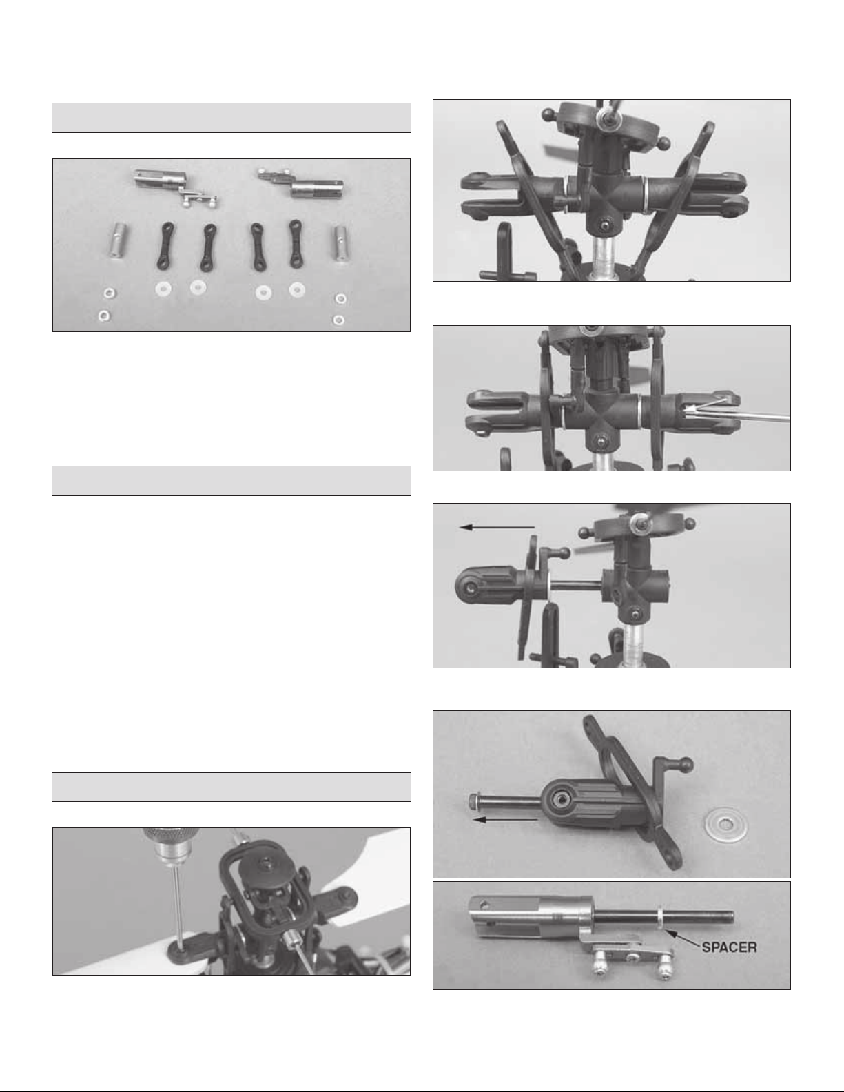
PACKAGE CONTENTS
• Two CNC Bell Hiller blade grips with mixers pre-installed
• Two brass fl ybar weights
• Four control rods
• Two short spacers
• T wo long spacers
• Four plastic blade spacers
❏ 2. Remove the oval linkages from the swashplate and fl ybar
control arm.
INTRODUCTION
The Heli-Max™ AXE™ CP Bell Hiller Uprade increases the control
rate and stability of your AXE CP drastically. The included adjustable
fl ybar weights must be installed for initial test fl ights. The fl ybar
weights reduce the sensitivity of the control system. Please keep in
mind that even with the fl ybar weights installed, the model will be 4 to
5 times more sensitive once you install the Bell Hiller blade g rips.
Once you have become accustomed to the ne w Bell Hiller blade grips,
you will notice the model is much more responsive and accurate to
your control inputs. You will also notice the model can be fl own in
stronger winds and fast forw ard fl ight sho ws no instabilities.
If additional assistance is required for any reason contact Product
Support by e-mail at helihotline@hobbico.com, by telephone at
(217) 398-8970, or visit www.helimax-rc.com.
INST ALLING THE UPGRADE
❏ 3. Remove the spindle bolt using a 1.5mm allen wrench.
❏ 4. Remove the blade grip from the side you removed the spindle
screw from. Pull the other blade g rip and spindle out of the head bloc k.
❏ 1. Remove the main blade bolts using a 1.5mm allen wrench.
Remove both main rotor blades from the helicopter. Remove the
2mm nut from the bottom of the blade grips. These will be needed
later when reinstalling main rotor blades.
❏ 5. Slide the spindle out of the blade grip and inser t the spindle
into the new Bell Hiller blade grip. Slide a thin dampening spacer
onto the spindle.
Page 2
❏ 6. Using a 1.5mm allen k ey, push the new blade g rip and spindle
through the dampeners. Install the other thin dampening spacer
onto the spindle as shown.
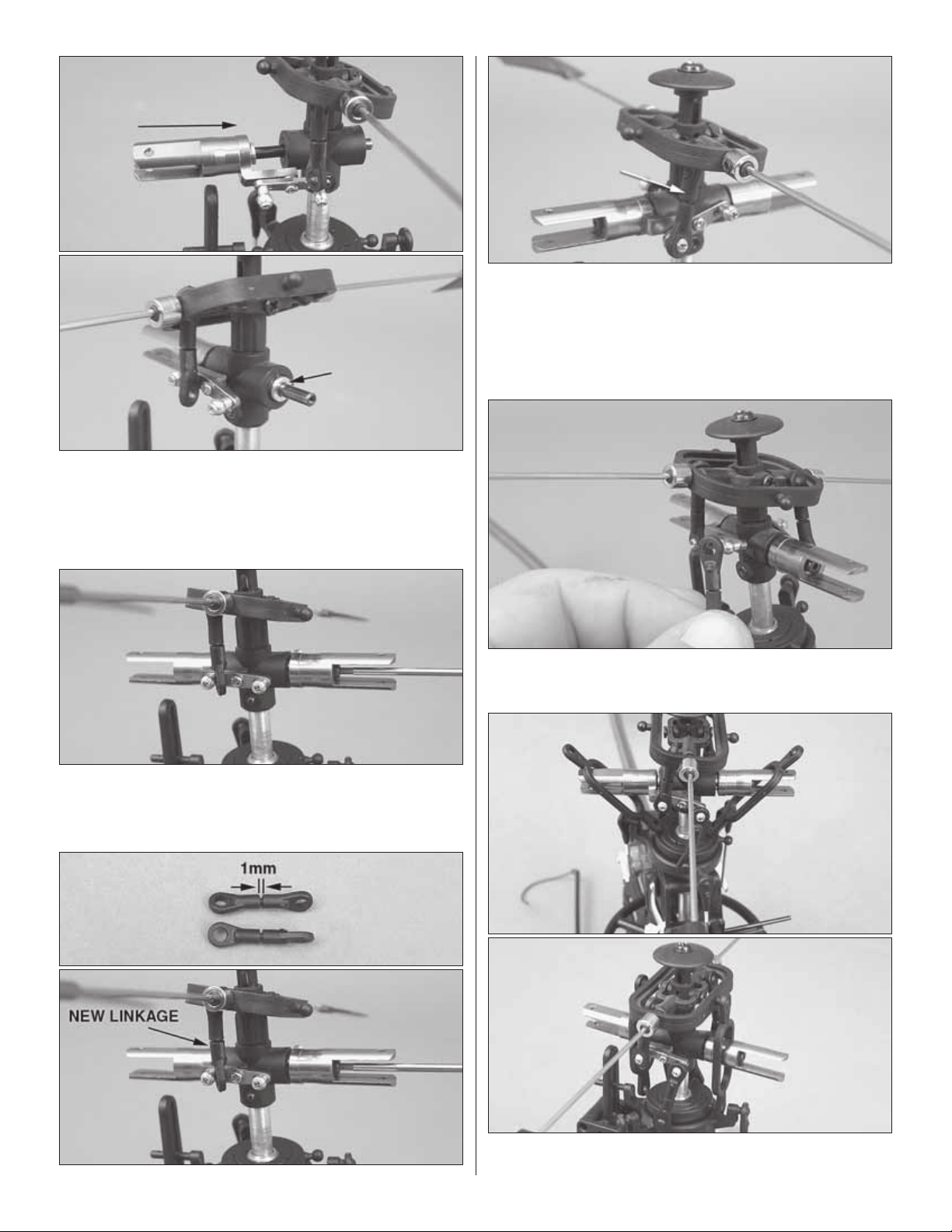
❏ 8. Remove all of the control links from the rotor head. Verify the
new linkages are the same length and have a 1mm gap between
the ball links. Please note there is a dimple on one side of the ball
link. The dimple must be on the outside as you snap the linkage
onto the ball. Install the new control linkage between the fl ybar
seesaw and the blade grip mixer arm as shown above. Repeat this
for the opposite blade grip.
❏ 9. Install the control linkage between the blade grip mixer arm
inner ball and the swashplate.
❏ 7. Place the remaining blade grip onto the spindle. Apply threadlocking
compound to the 2mm spindle bolt and re-install into the spindle.
Attention: The following step is very critical!
❏ 10. Slide the oval links over the blade grips and re-install them
onto the fl ybar control arm and the swashplate.
2
Page 3

❏ 11. Slide one thin n ylon washer onto the 2mm main b lade screw.
Slide the screw with washer through the blade grip and place one
thin nylon washer onto the opposite side. Carefully slide the blade
and washers into the blade grip. Apply threadlocking compound to
the blade bolt and install it using the 2mm nut removed from the
blade grip earlier. Repeat for the opposite blade grip.
❏ 12. Remove a paddle from the fl ybar. Install one brass paddle
weight onto the fl ybar and re-install the fl ybar paddle. Repeat on
the opposite side. Slide the paddle weights against the paddles
and tighten the set screws against the fl ybar. Measure and verify
both paddles are the same distance out from the fl ybar control arm.
Both paddles must be parallel with the swashplate. If you feel the
paddles rotate too easily, add a drop of CA to the threads before
threading the paddles on.
SETUP
WARNING! Unplug the main motor and tail motor before
proceeding to the following steps.
❏ 1. Once you are certain the main motor and tail motor are
disconnected, turn the transmitter on, center all trims, place the
throttle at the 50% position and fl ip the Idle Up switch to the “ON”
position. Plug the fl ight battery into the E-Board and allow the gyro 10
seconds to initialize. Hold the fl ybar level and the blades should be
3
Page 4

parallel to the fl ybar, which is 0 degrees collective pitch. If the blades
are not 0 degrees, then adjust the top linkage until they are. The
linkages on each blade grip must be the same length.
❏ 2. Raise the throttle to the uppermost position and you should
have 10° of top end pitch.
❏ 3. Lower the collective stick to the bottom position. You should
have -10° of pitch.
❏ 4. Unplug the fl ight battery, turn the Idle Up switch off, and
remove the fl ight battery. Plug the tail motor and main motor back
into the respective plugs.
The Axe CP is now ready to fl y. Perform the tracking test as
mentioned in the AXE CP instruction manual and if an adjustment
is needed use the linkage shown above.
Please Note: The Axe CP with the new Bell Hiller Head will be
much more responsive to your inputs in comparison to the original
Axe CP Head. Please take your time and become accustomed to
the new feel before you progress into forward fl ight or aerobatics.
Happy Flying!
HMXE7459INST1
 Loading...