

Page 1
®
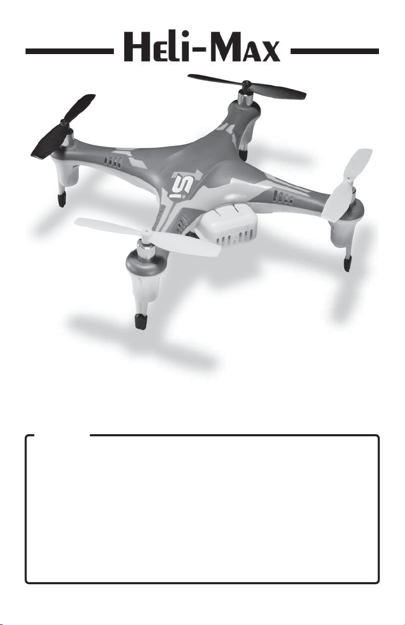
1Si Quadcopter
Instruction Manual
WARNING
Please fully read and understand this manual and the operation and all
safety aspects required of you for the safe operation of this product.
Before use, if you feel this product is not for you please return it to your
place of purchase.
Heli-Max products are to be used by ages 14 and over.
Manual Specifications and Description Changes
The instruction manual, warranties and other associated documentation
is subject to change without notice. Hobbico assumes no responsibility
for inadvertent errors to this manual.
Entire Contents © 2013 Hobbico®, Inc. HMXE0830 RTF v2 w/o camera HMXE0832 RTF v2 with camera
Page 2
®
INTRODUCTION
INTRODUCTION
Thank you for purchasing the Heli-Max 1Si Quadcopter. We are certain you
will get many hours of enjoyment out of this model. If you should have any
questions or concerns please feel free to contact us at: helihotline@hobbico.
com. For the latest technical updates or manual corrections visit the Heli-Max
web site at www.helimax-rc.com. If there is any new technical information,
changes or important updates to this model a “tech notice” box will appear
on the 1Si product page. Click the “tech notice” box to learn more about this
important update.
When you see this symbol, please pay special attention
and heed all warnings regarding the information within.
®
TECHNICAL SUPPORT
TECHNICAL SUPPORT
Please note that we cannot provide you information on the pricing you will
fi nd in your local retailer’s store for any products.
If you need technical support or have any questions, you can reach us by
one of the following means. When contacting us, please include the name of
the product you are referring to, its stock number and as much information
about your question or issue as possible.
For support outside the U.S. or Canada, please contact the distributor in your
country. If unable to contact the appropriate distributor, please contact us.
However, we are unable to respond to emails in languages other than English.
Email
Email us at helihotline@hobbico.com. Please try to include as much
information as possible when asking your question. Also please be sure
to list your full email address (ex: johndoe@aol.com) as well as at least one
other means of daytime contact in your email.
Phone
1-217-398-8970 Select option 6.
Available Monday-Friday, 8am-5pm
U.S. Central Time.
Fax
1-217-398-7721 Please be sure to
include a daytime telephone number
or return fax number so that we can
contact you.
Regular Mail
If you prefer, we can always respond with a regular mailed letter. Simply write
to us, including a brief explanation of your problem or question along with the
product name you are referring to. Use the Hobby Services address below.
2
Page 3
®
WARRANTY SERVICE
WARRANTY SERVICE
Heli-Max guarantees this kit to be free from defects in both material and
workmanship at the date of purchase. This warranty does not cover any
component parts damaged by use or modification. In no case shall Heli-
Max’s liability exceed the original cost of the purchased kit. Further,
Heli-Max reserves the right to change or modify this warranty without notice.
In that Heli-Max has no control over the final assembly or material used for
final assembly, no liability shall be assumed nor accepted for any damage
resulting from the use by the user of the final user-assembled product. By
the act of using the user assembled product, the user accepts all resulting
liability. If the buyer is not prepared to accept the liability associated with
the use of this product, the buyer is advised to return this kit immediately in
new and unused condition to the place of purchase.
To make a warranty claim, Hobby Services
send the defective part 3002 N. Apollo Dr., Suite 1
or item to Hobby Services Champaign, IL 61822
at this address. USA
Include a letter stating your name, return shipping address, as much contact
information as possible (daytime telephone number, fax number, e-mail
address), a detailed description of the problem and a photocopy of the
purchase receipt. Upon receipt of the package the problem will be evaluated
as quickly as possible.
®
2
6
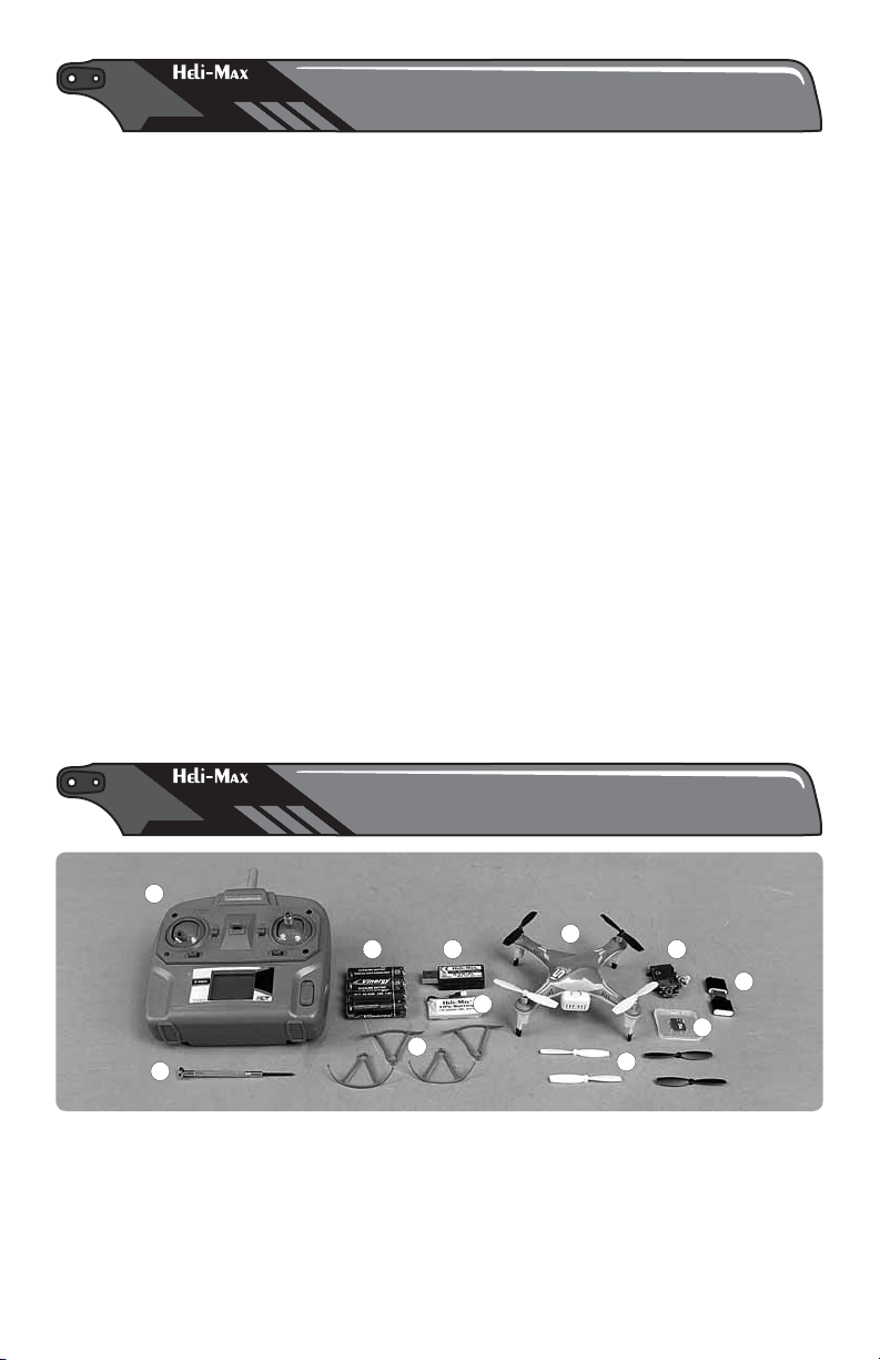
1. 1Si Quadcopter
2. HMX 465 SLT Transmitter
3. Heli-Max 350mAh LiPo
Battery pack (1)
4. USB Charger
RTF KIT CONTENTS
RTF KIT CONTENTS
8
4
3
7
1
5. Extra set of blades, 2 black,
2 white
6. Small Phillips screwdriver
7. 4 Blade Guards with screws,
2 gray, 2 white
8. AA Batteries (4)
3
11
10
9
5
9. 2G MicroSD card
(HMXE0832 only)
10. Card reader
(HMXE0832 only)
11. Camera
(HMXE0832 only)
Page 4
®
FEATURES & SPECIFICATIONS
FEATURES & SPECIFICATIONS
Features
● Switchable TAGS-FX™ Sensor Fusion stabilization system
● On board micro digital video camera (HMXE0832 only)
● On board micro snap-shot digital picture camera (HMXE0832 only)
● USB MicroSD Card reader (HMXE0832 only)
● 2G MicroSD removable card (HMXE0832 only)
● LEDs for orientation built into frame
● Actual Direction Control fl ight mode
● Auto Return function
● Optional rotor blade guards
Product Specifi cations
Size: 125mm (4.92") Quadcopter (Diagonal from motor
center to motor center)
Motors: 20×7 Coreless (4)
Empty Weight: 31g (1.09 oz) 35g with camera
Weight RTF: 41g (1.62 oz) 45 g with camera
Blade Length: 56 mm (2.20")
Overall Length: 138 mm (5.44")
Height: 45 mm (1.77")
Width: 138mm (5.44")
Camera Specifi cations
Memory: Accepts MicroSD card
Size: 40 mm×20 mm×8 mm L×W×H
Codec Video: Motion JPEG, 1280×720, 30 fps, file extension .avi
Codec Audio: PCM S16 LE, mono
Still Image capture: 1280×720, 96 dpi, file extension .jpg
®
SAFETY PRECAUTIONS
SAFETY PRECAUTIONS
Operational Warnings
Failure to follow these safety precautions may result in injury
to yourself and others.
● Keep your face and body as well as all spectators away from the rotating
blades whenever the battery is connected.
● Keep loose clothing, shirt sleeves, ties, scarfs, long hair or loose objects
such as pencils or screwdrivers that may fall out of shirt or jacket pockets
4
Page 5
away from the rotors. The spinning blades of a model of this type can
cause serious injury.
● When choosing a fl ying site stay clear of buildings, trees and power lines.
AVOID fl ying in or near crowded areas.
● DO NOT fl y close to people or pets. Maintain a safe distance from the
quadcopter.
● Do not alter or modify the model. Doing so may result in an unsafe or un-
fl yable model.
● When and if repairs are necessary you must correctly install all components
so that the model operates properly on the ground and in the air. Please
check the operation of the model before every fl ight to insure that all
equipment is operating and that the model has remained structurally sound.
● Please allow a 10 minute cool down period after each fl ight so the motor
controller and motors can cool down. Failure to do so may cause loss of
control due to the controller overheating and shutting down.
● Inspect the rotor blades before each fl ight for nicks. If any damage is found
or if the blades have been damaged, replace the blades before fl ying the
model again.
● After a crash you must inspect all plastic parts on the quadcopter for
damage before attempting to fl y the model again.
Battery Warnings and Usage Guidelines
Please read and understand the following regarding the usage
of LiPo batteries.
● NOTE: Heli-Max Quadcopter battery packs are not
cross compatible with Heli-Max NOVUS brand battery
packs or chargers.
● Through the use of the included LiPo battery you have assumed all risk
and responsibility regarding a LiPo battery and its use.
● ALWAYS unplug your battery from either the charger or Quadcopter after use.
NEVER store your Quadcopter with the battery plugged into the Quadcopter.
● Do not attempt to charge your battery if it becomes swollen or hot.
● It’s best to store your batteries charged and at room temperature. Storing
a fully discharged battery may cause irreversible damage to the battery.
● Never disassemble, puncture or modify the battery pack in anyway.
● Never allow the battery temperature to exceed 150° F [65° C].
● If your battery begins to swell or “puff” during charge or discharge or
becomes damaged in any way, stop using it and contact Hobby Services
at 217-398-0007 to learn the proper way to dispose of your battery.
5
Page 6
Charge Warnings
● Only use the included charger with the included LiPo battery.
Do not attempt to use the provided charger with NiCd, NiMH
or batteries with other chemistries.
● Do not leave the charger unattended while in use and always charge your
battery in a fi re-resistant location.
● Disconnect the battery and remove input power from the charger immediately
if either becomes hot!
● Do not allow water or other foreign objects to enter the charger. Keep the
charger away from moisture and do not submerge in water.
● Please keep all electronic components out of the reach of children!
®
BATTERY CHARGING
BATTERY CHARGING
● WARNING!! The charger supplied with the Heli-Max 1Si
Quadcopter contains protective circuitry. If you experience any
difficulties while charging the battery, please disconnect the
battery from the charger and unplug the charger from the power
source. Allow the battery and charger to rest for two hours as this will allow
the charge protection circuit to reset. If this issue re-occurs during normal
use, please contact technical support for further assistance.
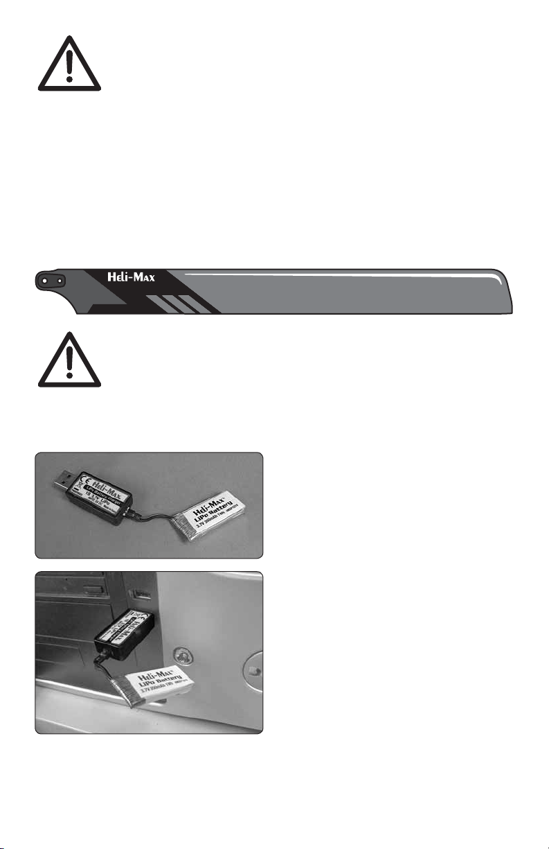
❏ Plug the flight battery into the end
of the USB charger.
❏ Plug charger into a USB port. A
steady red light will glow letting you
know the battery is charging. The light
will flash slowly when the charge is
complete. Remove the battery from
the charger. Under normal operating
conditions, the battery may take up to
60 minutes to recharge. Never leave
the battery attached to the charger
after charging is complete.
NOTE: A fast flash indicates a charge error. This is usually an indication that
your battery is defective and should be replaced.
6
Page 7

Transmitter Setup
❏ Turn the Transmitter on and make
sure that there is a blue light behind
the Heli-Max panel at the top of the
transmitter. The LCD screen should
be on, with a throttle position indicator
and other information.
❏ Install 4 AA batteries in the
transmitter by removing the
battery cover from the back of
the transmitter. Double-check the
polarity of each battery before
replacing the battery cover.
❏ Make sure the electronic trim
indicators on the display are centered.
®
TRANSMITTER CONTROLS
TRANSMITTER CONTROLS
All controls are described with the tail pointing directly toward you. This is
the best way to fly in the beginning since it keeps the control inputs oriented
the same direction.
7
Page 8

®
INSTALLING THE BLADE GUARDS
INSTALLING THE BLADE GUARDS
Installing the optional rotor blade guards is recommended. Besides protecting
the rotor blades from damage, these parts can also allow the 1Si to continue
to fl y if it brushes up against a wall or other solid object.
8
Page 9

❏ Secure the guard to the frame with
the included screw.
®
FLYING YOUR 1Si QUADCOPTER
FLYING YOUR 1Si QUADCOPTER
Electric motors are very dangerous. Do not work on the model
while the flight battery is plugged in as interference may cause
the main rotor blades to spin, possibly causing injury.
❏ Slide the guard over the motor and
position the hole for the mounting
screw over the dimple on the top of
the arm.
Turn on the transmitter and lay it down
so the antenna is pointed at the LED
on the back of the 1Si as shown in the
photo. Connect the flight battery to
the quadcopter. Do not move the 1Si
or the transmitter until the LED stops
flashing and is steady. This procedure
will help the 1Si to maintain the correct
orientation while in flight or returning
to home position.
NOTE: The 1Si will be “ON” at this point. Your quadcopter has a safe start
feature built in that prevents the motor from activating unless the throttle
stick has been lowered to the lowest position. If the motors won’t run,
please make sure the throttle stick is all the way down and the throttle
trim is at or below center. Wait a couple of seconds and try advancing the
throttle again.
Takeoff
Advance the throttle until the model is at least a foot off the ground and out
of ground effect. If flying outdoors it’s important to stick to light winds. If you
plan to take off and land in grass, place a rubber mat or pad down on the
grass so the small rotating parts don’t get hung up in the grass.
9
Page 10

Hovering
Once the quad is in the air simply try to keep it in one spot. This will take
some practice. Remember that even a light breeze will have an effect on the
stability of the quad.
Landing
Level the quad into a steady hover and slowly decrease power until it lands.
You might notice as the Quadcopter is ready to touch down it moves around
a little. This is normal as the Quadcopter enters ground effect.
®
BASIC MANEUVERS
BASIC MANEUVERS
Once you are comfortable with hovering in one place start working on
orientations. By this we mean, hover the Quadcopter in all positions, nose
to the right, nose to the left and the nose pointing at you (nose-in). Getting
good at this fundamental discipline will allow you to progress much faster
in some of the more advanced flying maneuvers.
Slow Pirouettes
Move the left stick (left or right) you can rotate the Quadcopter around 360°,
which is called a pirouette.
Forward Flight
Now it’s time to work into basic forward flight. Just take the basic hovering
maneuvers listed above and slowly fly out farther and faster and always
bring the Quadcopter back after one pass. Practice controlled slow flight in
close as well. The more time you spend practicing here, the easier things
will be later on.
®
POST-FLIGHT PROCEDURES
POST-FLIGHT PROCEDURES
Before turning off the transmitter, make sure that all the trim indicators
on the transmitter are centered. If you fi nd that the model is consistently
drifting in one direction, the sensors on the 1Si may need to be re-calibrated
(see Troubleshooting).
Remove the battery from the 1Si. Allow it cool to room temperature and
recharge it. Do not leave the battery connected to the 1Si after the fl ight is
completed.
10
Page 11

If the model is to be stored for a long time period, please remove the batteries
from the transmitter to avoid damage to the contacts. If storing the model for
several weeks, the batteries for the quadcopter should be charged to 50%
of a full charge and checked after 3 to 4 months.
®
FLIGHT MODE OPTIONS
FLIGHT MODE OPTIONS
Dual Rate
The TX465 transmitter has a dual rate
function. This feature toggles between
a fl ight mode that reduces the model’s
range of motion to make the 1Si easer
to fl y and one that allows the full range
of motion so the 1Si can fl y in a more
aggressive manner. To toggle between
these two fl ight modes, press down
on the right control stick and release
it. When the transmitter is in low rates, the ellipse in the lower center of the
LCD screen will show a half ellipse and emit a single low pitch single beep.
For high rates, the ellipse will be complete and the transmitter will emit a
single high pitch beep.
Flight Control Sensitivity
You can also make the transmitter for the 1Si more or less sensitive by
changing the control setting. To do this, press and hold the right stick down.
When the transmitter starts to beep continuously, move the throttle up or
down to adjust the sensitivity percentage which will be indicated on the LCD
screen. A higher value will make the controls more sensitive. When you have
the desired setting, release the right stick and return the throttle to 0%. We
have found that 30% is good all-around setting. Warning: If this value gets
bumped to 0 your quadcopter will respond very slowly to any right stick input.
Beginner/Expert Mode
When the 1si is turned on it will be in Beginner Mode. In this mode, the
control board will apply “Braking” to slow the 1Si and bring the model to a
hover when the right sticks are released. The quad will be very smooth and
stable in this mode.
Press the “F Mode” button on the upper right corner of the transmitter to
enter the Expert Mode. The LED on the back of the 1Si will fl ash twice, stay
off for a second, fl ash twice again, and then remain on. When the quadcopter
is in this mode, the accelerometers are disabled and the 1Si will not slow
down when the right stick is centered. This mode also will allow the 1Si to
fl y more aggressively.
11
Page 12

To return to the normal fl ight mode, press the “F Mode” button again. The
rear LED will fl ash twice, stay on for a second, fl ash twice again, and then
remain steady. This sequence indicates that the accelerometers and the
Braking function are active again.
Actual Direction Control
When the “ICM” button on the upper left corner of the transmitter is pressed
for at least 3 seconds, the 1Si will enter the “Actual Direction Control” flight
mode and the LED on the back of quadcopter will flash slowly. In this mode,
the 1Si will use the pilot’s position as a reference point for any signal received
from the right stick on the transmitter. Moving stick forward or backward
will move the quadcopter farther or close to the pilot. The direction that the
front of the 1Si is facing will not have any effect while in this mode. The
antenna on the transmitter must be pointed at the quadcopter at all times
to help the model maintain its position while in flight.
To exit the “Actual Direction Control” mode, press the ICM button again for
3 seconds. The rear LED will become steady to indicate that it is now in the
normal flight mode.
Adjustment Mode
The 1Si will have to be put in the Adjustment
Mode before any adjustments to the return
speed or the sensors can be performed.
1. Turn on the transmitter and connect the
battery to the quad so it can link. Keep
the antenna pointed at the LED on the
1Si until the linking process is completed.
2. Press down on the right stick and hold
it down until the transmitter starts to beep. Continue to hold down the right
stick until the next step is completed.
3. Press down the left stick 4 times and then release both sticks. Push up on
the elevator trim button once and release it. At the same time, watch the display
for a change on the elevator trim indicator. If the indicator does not move, the
transmitter and 1Si are in the Adjustment Mode. Note: Pressing down on the
left stick at any time will cause the transmitter to exit the Adjustment Mode.
Auto Return
To make the 1Si return to you, press the ICM on the upper left corner of the
transmitter quickly and release it. The rear LED will flash quickly and model
will start to fly toward the transmitter. The pilot can use the throttle to control
the altitude, but any movement with the right stick will cause the model to
return to the normal flight mode. When the model gets close, the pilot should
expect to use the transmitter to slow the 1Si and bring it to a hover. Note:
The transmitter antenna should point at the quadcopter at all times to
help keep the 1Si on course.
12
Page 13

This procedure should be used if the return speed of the 1Si needs to be
changed.
1. Enter the Adjustment Mode as described earlier.
2. Push the rudder trim button to the left increase the return speed. The
longer the button is held to the left, the LED on the 1Si will fl ash faster
and the tone will increase in pitch to indicate that a higher return speed is
being selected. When the LED remains steady, the highest speed has been
selected. Moving the button to the right will reduce the return speed. The
LED will fl ash slower and the pitch will be lower to indicate the speed that is
being selected. When the LED turns off, the lowest speed has been selected.
3. Press down on the left stick to exit the Adjustment Mode when the desired
speed has been selected.
®
CAMERA OPERATION
CAMERA OPERATION
The camera will be in VIDEO mode when it is fi rst powered up. Press the
VIDEO button to start recording a video. You will see the LED on the side of
the camera fl ash slowly while the video is being captured. To stop recording
and store the video, press the VIDEO button again. The LED will stop fl ashing
to indicate that the camera is ready for use. If the card is removed or the
battery unplugged while the camera is recording, the video will NOT be
saved on the card.
Before the camera can take a photo, it must be in the Picture mode. Press
the PICTURE button one time, to change the mode. The LED on the camera
will remain steady while the camera mode is changed. Press the PICTURE
button to take a photo. You will notice that the LED will fl ash rapidly as the
picture is recorded and stored on the microSD card. When the LED stops
fl ashing, the camera is ready to take another photo. If the Picture button is
pressed while the LED is fl ashing, the camera will not capture another photo.
The VIDEO button must be pressed once to change modes before the camera
will capture a video.
Installing the MicroSD Card
To minimize any chance of data being lost
on the microSD card, do not insert or remove
the card from the camera until the battery
has been unplugged from the quadcopter.
Remove the SD card from the protective
case. Flip the model over and push the card
into the slot on the side of the camera
module. When the card is correctly installed,
it will click. To remove the card, simply press
13
Page 14

on the card again and the inner spring system will help eject the card. Note:
The card must be in place to capture video or Pictures. The camera has no
internal memory.
Downloading the video and pictures from the camera:
Install the MicroSD card into the reader.
Plug the reader into the USB port of
your computer.
The USB connection will be auto
recognized and the files ready to be
transferred.
At this point you can copy or transfer
your files to your folder structure.
®
TROUBLESHOOTING
PROBLEM: 1Si does not react to any stick movements.
Solution 1: Make sure that the battery voltage is above 4.0 volts
Solution 2: If the LED on the rear of the model is not steady, unplug the
battery and turn off the transmitter to allow the control board to reset itself.
After about a minute, turn on the transmitter and reconnect the battery.
TROUBLESHOOTING
PROBLEM: Flies with poor power or buzzes.
Solution: One of the props may be bent. Carefully bend it straight.
PROBLEM: You notice that one of the motors spins noticeably slower
or feels tight.
Solution: Replace the motor. This is done by removing all 4 props and
loosening the screws holding the frame together. Remove the top of
the frame and unplug the defective motor wire from the control board.
The LED board can be popped off the alignment posts with a small
screwdriver. The motor will slide out of the frame and the new motor/
LED board can now be installed. A couple of small pieces of tape will
hold the LED board in place.
PROBLEM: The 1SI will not return directly to you in Auto Return mode.
Solution: Calibrate the transmitter and or the control board.
14
Page 15

Control Board Sensor Calibration
1. Enter the Adjustment Mode as described on page 12.
2. Press up on the throttle trim button and the rear LED on the 1Si will
start flashing rapidly.
3. When the LED stops flashing, press down on the left stick to exit.
If you still have problems, try the tip on page 17.
Transmitter Calibration
Press on the ICM button while turning on the transmitter. The display will
show a “1” briefly then display a “2”.
Place the transmitter down on its
back with the antenna pointed
away from you. Slowly rotate
the transmitter clockwise three
times, then three times counterclockwise.
Pick the transmitter up by the
sides and rotate it so the antenna
moves toward you. Rotate it three
times, then three more times in the
opposite direction.
Hold the transmitter by the
antenna and bottom with antenna
pointed away from you. Rotate
the transmitter left to right three
times. Rotate it three more times
from right to left.
15
Page 16

Hold the transmitter by the upper
right corner and lower left corner
so the antenna is pointed 45
degrees to the right. Rotate the
transmitter three times with the
antenna moving toward you, then
three more times in the opposite
direction.
Put the transmitter down with the antenna pointed away from you and
push the ICM button. The display should read “0”.
Press the F Mode button. The display will indicate 90 and the transmitter
should be rotated so the antenna
is at 90 degrees. Each time the
F Mode button is pressed, the
display will increase 90 degrees
and the transmitter should be
rotated to that position before the
button is pressed again. When the
display reads “0”, press the F Mode
button to exit the calibration mode.
This procedure will usually correct problems with the Auto Return or
Actual Direction Control modes. If you continue to have problems, please
try the model in another area. There may be some interference in your
flying location that is affecting the sensors.
REAR LED CODES
THIS SIGNAL MEANS THAT THE
1 Long, 3 Short, Off, 1 Long, 3 Short …
Steady
1 Short, Off (rapidly flashing)
1 Long, Off (slowly flashing)
2 Short, Off, 2 Short, Remains ON
2 Short, 1 Long, 2 Short, Remains On
Control board is not linked with transmitter
1Si is ready for flight
Auto Return mode is active
Active Direction Control mode is active
1Si is changing to Manual Flight mode
1Si is changing to Normal Flight mode
PROBLEM: The Camera System will not take a photo or start recording
a video.
Solution 1: Install the microSD card if it is not in the slot.
Solution 2: Eject the card and check for any debris on the contacts.
16
Page 17

Solution 3: Make sure card is OK by putting the card in reader and
checking on your PC.
PROBLEM: 1Si drifts while hovering.
Solution: Use the following procedure to re-calibrate the neutral setting
on the 1Si.
1. Enter the Adjustment mode as described on page 12.
2. The quadcopter should be hovered about 3 feet above the floor in a
calm area without any wind or drafts. Release both sticks for a second
or two and observe the 1Si’s behavior. If the quadcopter drifts forward
or backward, move the elevator trim in the opposite direction until the
model remains in place. Use the aileron trim below the right stick in the
same manner to correct for any drifting side to side.
3. Press down on the left stick to exit the Adjustment mode when the
quadcopter has been trimmed.
®
MAINTENANCE
MAINTENANCE
When installing the rotor blades on the 1Si, please use this photo as a guide.
There is also an arrow molded on the frame to show the direction the rotor
blades will spin.
17
Page 18

®
REPLACEMENT PARTS
Key Part No. Description
1 HMXE2203 Blade Guard (4)
2 HMXE2202 Rotor Blades Black / White
3 HMXE2244 Body / Frame Gray
4 HMXM2053 TAGS-FX Controller Board
5 HMXE2241 Motor/LED Right Front CCW 1Si
6 HMXE2240 Motor/LED Left Front CW 1Si
7 HMXE2243 Motor/LED Right Rear CW 1Si
8 HMXE2242 Motor/LED Left Rear CCW 1Si
9 HMXE2180 Control Board Dampeners
10 HMXE2245 Receiver Mount
11 HMXP1015 LiPo 1S 3.7V 350mAh
12 HMXZ0001 Video / Picture Camera
13 HMXE7339 Screw Set
14 HMXE2246 Landing Pads (4)
HMXJ2029 TX465 Transmitter SLT
HMXP2023 USB Charger
HMXZ0002 USB MicroSD Reader
REPLACEMENT PARTS
18
Page 19

®
EXPLODED VIEW
EXPLODED VIEW
13
1
1
2
2
13
4
9
13
10
11
12
5
6
14
7
3
8
3
13
19
Page 20

®
Entire Contents © 2013 Hobbico®, Inc. HMXE0830 RTF v2 w/o camera HMXE0832 RTF v2 with camera
20
 Loading...