

Page 1
™
™
INTRODUCTION
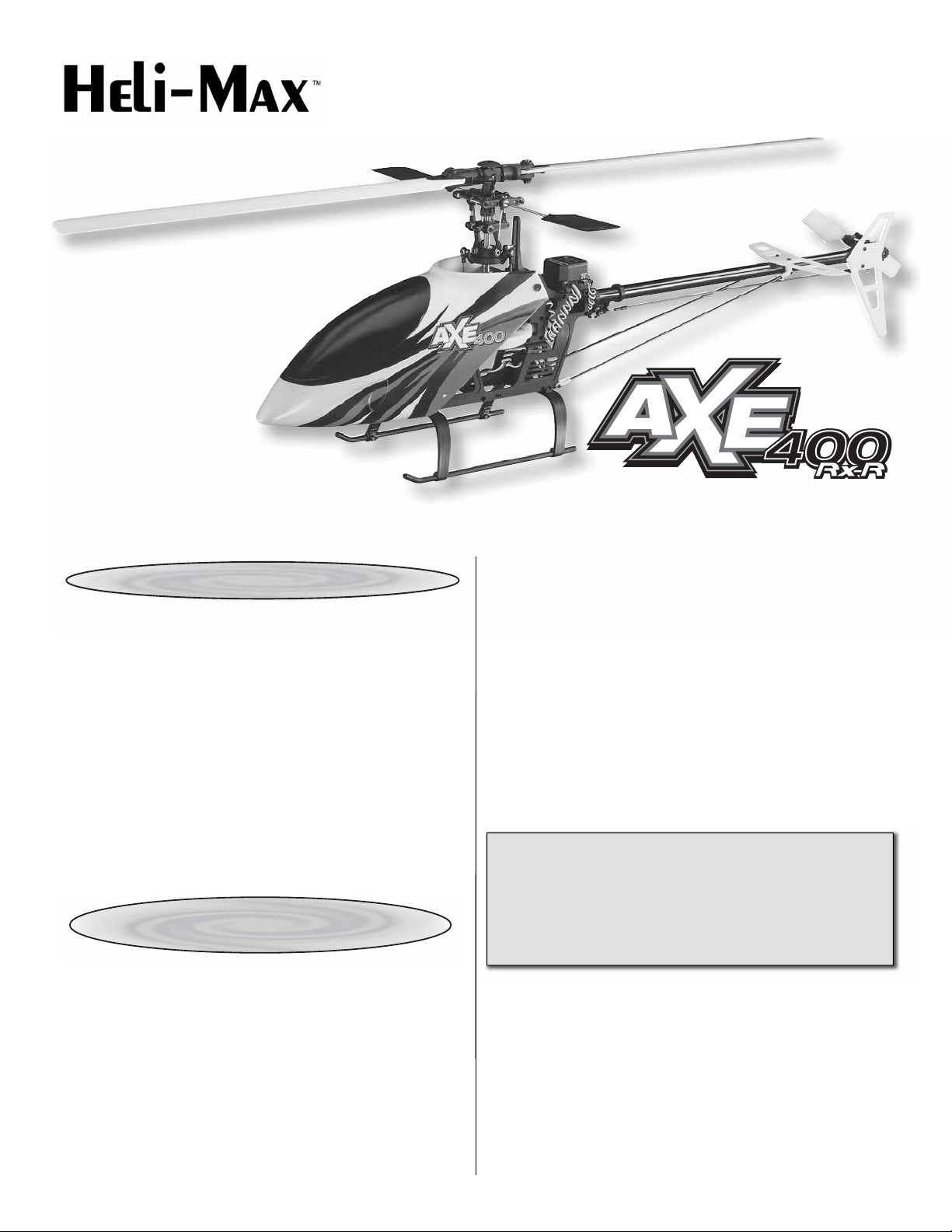
Thank you for purchasing the Heli-Max AXE™ 400 3D
Rx-R Helicopter. We are certain you will get many hours of
enjoyment out of this model. If you should have any questions
or concerns, please feel free to contact us at:
helihotline@hobbico.com.
For the latest technical updates or manual corrections to the AXE
400 3D Rx-R, visit the Heli-Max web site at www.helimax-rc.
com. Open the “Helicopters” link, and then select the 400 3D
Rx-R. If there is new technical information or changes to this
model, a “tech notice” box will appear in the upper left corner of
the page.
ITEMS THAT MUST BE
PURCHASED SEPARATELY
RADIO SYSTEM
Minimum 6-Channel Helicopter Radio
• FUTK6900 Futaba® 6EX 6-Channel 2.4GHz Transmitter/
Receiver
• FUTK7005 Futaba 7C 7-Channel 2.4GHz Heli Tx/Rx
No Servos
• FUTK9251 Futaba 10C 10-Channel 2.4GHz Heli Tx/Rx
Mode 2
FLIGHT BATTERY
Hovering, Basic Aerobatics and 3D
• GPMP0406 11.1V 2000mAh Battery LiPo Flight Battery
• GPMP0617 Great Planes® ElectriFly™ LiPo 11.1V
2200mAh 25C Power Series
Hovering, Basic Aerobatics, Mild 3D and Aggressive 3D
• GPMP0520 Great Planes LiPo 11.1V 2200mAh 25C
T-Rex MX450 Heli
• FPWP0327 FlightPower LiPo 11.1V 2170mAh 25C
EVO25 3S Balance
Also required is an appropriate battery charger for your
fl ight battery.
WARNING: To prevent the possibility of the main
rotors turning during set up, you must disconnect the
main drive motor from the ESC or remove the pinion
gear from the motor. Failure to do this may result
in injury to yourself or damage to the model and its
surroundings.
Page 2
OPERATIONAL WARNINGS
CAUTION! A separate Battery Eliminator Circuit (BEC) must be used If you decide to change the stock servos (Futaba
S3114) to some other type of analog or digital servos. We highly recommend the Castle Creations CC BEC 10A Switching
Regulator (CSEM0005).
DANGER! Please allow a 10 minute cool down period after each fl ight for the Electronic Speed Control (ESC). Failure to do
so may cause loss of control due to the ESC overheating and shutting down.
DANGER! Please inspect the wooden main rotor blades before each fl ight for damage. If any damage is found or if the
blades have been crashed, please replace the blades before fl ying the model again.
CAUTION! If the rotor head speed ever drops suddenly in fl ight, please land the model immediately and remove the body.
Inspect the battery temperature and ensure that it has not exceeded 140°F. Also ensure that the ESC has not overheated.
The ESC does have a thermal protection built in that will reduce the power output to safe levels when the safe operating
temperatures have been exceeded. If this has occurred, please allow the model 10 minutes to cool down.
WARNING! The ESC does have a soft cut function that will reduce the power output to protect the fl ight battery. Toward the end
of a fl ight, if you notice a slight power reduction, land the model immediately and re-charge the battery. The fl ight time of the Axe
400 can be as long as 10 minutes, but this will vary depending on your fl ying style or how aggressively you fl y the model.
CAUTION! After a crash you must inspect all plastic and metal parts on the helicopter for damage before fl ying the model again.
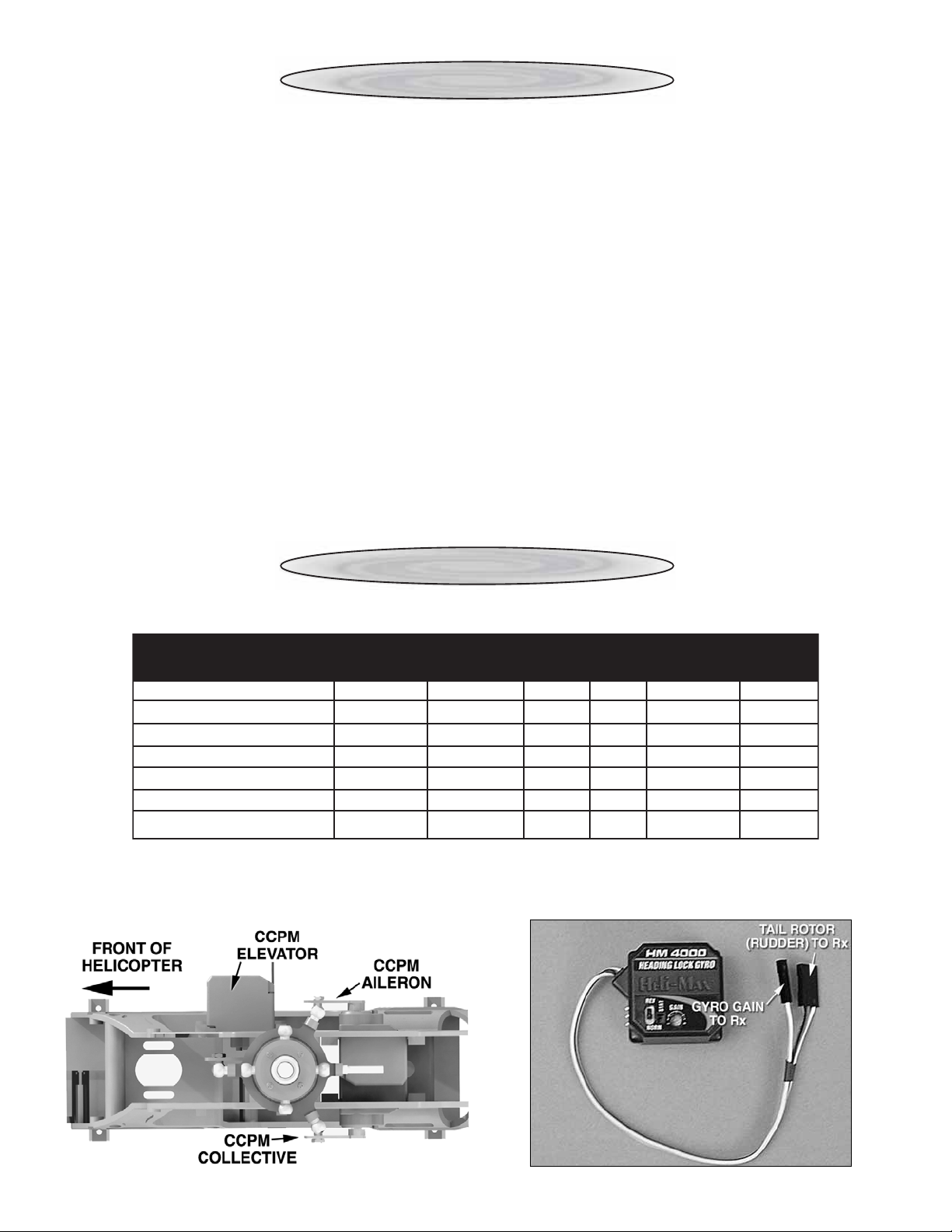
RECEIVER SERVO CONNECTIONS
CCPM
Receiver Type
Futaba PCM1024 / FM
Futaba 6/7CH FASST
Futaba FASST Multi
Hitec
JR
Airtronics
Multiplex
Using the table above, plug the Servos, Electronic Speed Control (ESC) and Gyro into the appropriate channels on the
receiver. Please refer to your manufacturer’s instructions for your transmitter to verify that these connections are correct.
Aileron
1
1
1
1
2
2
1
CCPM
Elevator
2
2
2
2
3
1
2
Tail
Rotor
4
4
4
4
4
4
3
Gyro
Gain
5
5
5
5
5
5
6
CCPM
Collective
6
6
3
6
6
6
4
Throttle
3
3
6
3
1
3
5
2
Page 3

SET UP QUICK REFERENCE
Please use this table as a reference while setting up the Axe 400 Rx-R. Please refer to your manufacturer’s transmitter
instructions to ensure that the model is set up correctly. Once the model is set up, verify that the controls operate as
described in the Heli-Max Axe 400 RTF manual.
Swashplate Type Futaba 6EX Futaba 7C Futaba 9C Futaba 10D Futaba 12 / 14
120° CCPM 3-S HR-3 HR-3 HR-3 HR-3
CCPM Elev
CCPM All Servo Servo Throttle Tail Rotor Gyro CCPM COL
Swash AFR Aileron +85% Elevator -85% COL +35%
EPA / ATV 100% / 100% 100% / 100% 100% / 100% 70% / 70% 100% / 100% 100% / 100%
D/R 100% H – 70% L 100% H – 70% L 100% H – 70% L
EXP -50% H – 35% L -50% H – 35% L -50% H – 35% L
Reverse
(Futaba Only) 1 – Reverse 2 – Normal 3 – Reverse 4 – Normal 5 – Normal 6 – Normal
Sub Trim 0 0 0 0 0 0
Trim Step* 4* -- 1 4* -- 1 4 4* -- 1
Fail Safe Low Throttle
GYRO Heading Hold
(Heading Hold) 45% Gain
HOV-THR INH - Best to use mechanical adjustments
HOV-PIT INH - Best to use mechanical adjustments
Throttle Hold ACT POS>+- 0% R-OF> INH RT>+- 0%
Throttle Curve
Normal 0% 32% 65% 82% 100%
Idle Up 1 100% 92% 85% 92% 100%
Pitch Curve
Normal 45% / -2° 47% 50% / 0° 75% 100% / +10°
Hold 30% / -4° 40% 50% / 0° 75% 100% / +10°
Idle Up 1 0% / -10° 25% 50% / 0° 75% 100% / +10°
Swash->
Throttle Mixing Idle Up Only Left/Right Cyclic 20% Forward/Aft Cyclic 20%
*Leave the trim step set to 4 until the initial trim fl ight is completed. Then you can reduce the trim step to 1 for a fi ner
adjustment.
FINAL SET UP
Mount the receiver using double sided tape as shown below. Using a wire tie, bundle the wires and place them on top of the receiver.
This ensures that the wires cannot become entangled in the main rotor gear or the counter gear that drives the tail rotor.
Disconnect the main drive motor from the ESC. Turn your
transmitter on. Install a fl ight battery into the helicopter and
connect the battery to the ESC. Allow the gyro 5 seconds
to initialize.
Verify that you have disconnected the drive motor. Carefully
raise the throttle stick to the middle position. The servos,
blade grips and all the mixing levers should be perfectly
level. If necessary please make adjustments to the servo
arms, linkages or to the radio set up. Linkage lengths are
listed in the Heli-Max Axe 400 RTF manual.
3
Page 4

PITCH RANGE
You may notice that the tail servo does not center when the
transmitter stick is returned to center. This is correct and how
a heading hold gyro operates. If the tail rotor servo always
returns to center, then you need to reverse the gyro gain
channel in the transmitter.
BEFORE FLYING THE MODEL
Once you have verifi ed the settings, please refer to the Axe 400
Ready To Fly manual for fi nal set up and fl ying instructions.
Thanks you for purchasing the Heli-Max Axe 400 Rx-R
and Happy Flying!
Pitch Curve
Normal
Hold
Idle Up 1
Low End
-2°
-4°
-10°
Mid Stick
0°
0°
0°
High End
+10°
+10°
+10°
Using a pitch gauge please verify the settings shown below.
GYRO SET UP
With the transmitter on and the fl ight battery connected, pick
the helicopter up by the main rotor head and rotate the nose
to the left (counterclockwise). Verify that the pitch slider on
the tail rotor moves in toward the tail gear box, applying right
tail rotor as the correction.
Entire Contents © Copyright 2008 HMXE0801MNL01
 Loading...