

Page 1

INSTRUCTION MANUAL
™
Bell, UH-1D Huey, emblems, logos, and body designs are trademarks of Textron Innovations Inc. and are used under license by Hobbico®, Inc.
Specifi cations
Length: 8.27 in [210mm]
Width: 1.93 in [49mm]
Height: 4.80 in [122mm]
Entire Contents © 2010 Hobbico®, Inc. HMXE0808
Rotor Span: 7.68 in [195mm]
Weight: 2.75 oz [78g]
(with supplied fl ight battery)
Page 2

IMPORTANT PRECAUTIONS
IMPORTANT PRECAUTIONS
● Only use the included charger with the included battery or replacement
part (GPMP0410).
● Do not attempt to use this charger with NiCd or NiMH battery packs.
● Never charge in excess of 4.20V per cell.
● If the battery should become damaged, discard it. Do not attempt to use
a damaged battery.
● Do not leave the charger unattended while charging. Disconnect the
battery and remove input power from the charger immediately if either
becomes hot! However, it is normal for the charger to get warm.
● Disconnect the battery from the charger and carefully move the battery
to a fi reproof location if the battery begins to swell or smoke!
● Never charge at currents greater than 1C.
● Always charge in a fi reproof location.
● Never trickle charge.
● Never allow the battery temperature to exceed 150° F [65° C].
● Never disassemble or modify pack wiring in any way or puncture cells.
● Never discharge below 2.75V per cell.
● Do not allow water, moisture or foreign objects into the charger.
● Do not block the air intake holes, which could cause the charger to
overheat.
● Do not place the charger or any battery on a fl ammable surface or near
a combustible material while in use.
● Do not charge on a carpet, cluttered workbench, paper, plastic, vinyl,
leather, wood, or inside an R/C model.
● Never charge inside a full-sized vehicle.
● Always disconnect the battery from the charger and the power supply
from the charger when not in use.
● Do not attempt to charge a battery if it is swollen or hot.
● ALWAYS KEEP OUT OF REACH OF CHILDREN.
2
Page 3

WARRANTY
WARRANTY
Heli-Max™ guarantees this kit to be free from defects in both material and
workmanship at the date of purchase. This warranty does not cover any
component parts damaged by use or modifi cation. In no case shall Heli-Max’s
liability exceed the original cost of the purchased kit. Further, Heli-Max
reserves the right to change or modify this warranty without notice.
In that Heli-Max has no control over the fi nal assembly or material used for fi nal
assembly, no liability shall be assumed nor accepted for any damage resulting
from the use by the user of the fi nal user-assembled product. By the act of
using the user-assembled product, the user accepts all resulting liability.
If the buyer is not prepared to accept the liability associated with the use
of this product, the buyer is advised to return this kit immediately in new
and unused condition to the place of purchase.
To make a warranty claim, send the defective part or item to Hobby Services at
this address.
Hobby Services
3002 N. Apollo Dr., Suite 1
Champaign, IL 61822
USA
Include a letter stating your name, return shipping address, as much contact
information as possible (daytime telephone number, fax number, e-mail
address), a detailed description of the problem and a photocopy of the purchase
receipt. Upon receipt of the package the problem will be evaluated as quickly
as possible.
READ THROUGH THIS MANUAL BEFORE STARTING CONSTRUCTION. IT
CONTAINS IMPORTANT INSTRUCTIONS AND WARNINGS CONCERNING
THE ASSEMBLY AND USE OF THIS MODEL.
3
Page 4

TABLE OF CONTENTS
TABLE OF CONTENTS
IMPORTANT PRECAUTIONS . . . . . . . . . . . . . . . . . . . . . . . . . . . . . . . . . . . . 2
WARRANTY. . . . . . . . . . . . . . . . . . . . . . . . . . . . . . . . . . . . . . . . . . . . . . . . . . 3
INTRODUCTION . . . . . . . . . . . . . . . . . . . . . . . . . . . . . . . . . . . . . . . . . . . . . . 5
SAFETY PRECAUTIONS. . . . . . . . . . . . . . . . . . . . . . . . . . . . . . . . . . . . . . . 5
ADDITIONAL ITEMS REQUIRED . . . . . . . . . . . . . . . . . . . . . . . . . . . . . . . . . 6
KIT INSPECTION. . . . . . . . . . . . . . . . . . . . . . . . . . . . . . . . . . . . . . . . . . . . . . 6
KIT CONTENTS. . . . . . . . . . . . . . . . . . . . . . . . . . . . . . . . . . . . . . . . . . . . . . . 6
TRANSMITTER FEATURES . . . . . . . . . . . . . . . . . . . . . . . . . . . . . . . . . . . . . .7
INSTALL THE TRANSMITTER BATTERIES . . . . . . . . . . . . . . . . . . . . . . . . . 8
CHARGING THE FLIGHT BATTERY. . . . . . . . . . . . . . . . . . . . . . . . . . . . . . . 9
LITHIUM BATTERY HANDLING & USAGE . . . . . . . . . . . . . . . . . . . . . . . . .11
ELECTRIC MOTOR WARNING . . . . . . . . . . . . . . . . . . . . . . . . . . . . . . . . . . .11
TURNING THE MODEL ON . . . . . . . . . . . . . . . . . . . . . . . . . . . . . . . . . . . . . 12
TRANSMITTER CONTROLS. . . . . . . . . . . . . . . . . . . . . . . . . . . . . . . . . . . . 14
FLYING. . . . . . . . . . . . . . . . . . . . . . . . . . . . . . . . . . . . . . . . . . . . . . . . . . . . . 18
MAINTENANCE & REPAIRS. . . . . . . . . . . . . . . . . . . . . . . . . . . . . . . . . . . . 20
TRANSMITTER SETTINGS . . . . . . . . . . . . . . . . . . . . . . . . . . . . . . . . . . . . . 25
TRANSMITTER SPECIFICATIONS . . . . . . . . . . . . . . . . . . . . . . . . . . . 25
STICK LENGTH ADJUSTMENT . . . . . . . . . . . . . . . . . . . . . . . . . . . . . 25
PROGRAMMING YOUR TRANSMITTER . . . . . . . . . . . . . . . . . . . . . . . . . . 26
NAVIGATING & SETTING VALUES. . . . . . . . . . . . . . . . . . . . . . . . . . . 26
CHANNEL REVERSING . . . . . . . . . . . . . . . . . . . . . . . . . . . . . . . . . . . .27
AUX CHANNEL . . . . . . . . . . . . . . . . . . . . . . . . . . . . . . . . . . . . . . . . . . .27
BUZZER SETTING. . . . . . . . . . . . . . . . . . . . . . . . . . . . . . . . . . . . . . . . .27
NOVUS 125FP DEFAULT SETTINGS . . . . . . . . . . . . . . . . . . . . . . . . . .27
E-BOARD ADJUSTMENTS. . . . . . . . . . . . . . . . . . . . . . . . . . . . . . . . . . . . . 28
ORDERING REPLACEMENT PARTS . . . . . . . . . . . . . . . . . . . . . . . . . . . . . 29
EXPLODED VIEW & PARTS LIST. . . . . . . . . . . . . . . . . . . . . . . . . . . . . . . . 30
4
Page 5
INTRODUCTION
INTRODUCTION
Thank you for purchasing the Heli-Max Novus UH-1D Huey CX Helicopter. We
are certain you will get many hours of enjoyment out of this model. If you should
have any questions or concerns please feel free to contact us at helihotline@
hobbico.com. For the latest technical updates or manual corrections to the
Novus Helicopter visit the Heli-Max web site at:
www.helimax-rc.com
Open the “Helicopters” link, and then select the Novus UH-1D Huey CX. If there
is new technical information or changes to this model a “tech notice” box will
appear in the upper left corner of the page.
SAFETY PRECAUTIONS
SAFETY PRECAUTIONS
Failure to follow these safety precautions may result in severe injury to
yourself and others.
Keep your face and body as well as all spectators away from the plane of
rotation of the rotors whenever the battery is connected.
Keep these items away from the rotors: loose clothing, shirt sleeves, ties, scarfs,
long hair or loose objects such as pencils or screwdrivers that may fall out of
shirt or jacket pockets into the rotors.
The spinning blades of a model helicopter can cause serious injury. When
choosing a fl ying site for your Novus UH-1D Huey CX, stay clear of buildings,
trees and power lines. AVOID fl ying in or near crowded areas. DO NOT fl y close
to people, children or pets. Maintain a safe pilot-to-helicopter distance while fl ying.
Your Novus UH-1D Huey CX should not be considered a toy, but rather a
sophisticated, working model that functions very much like a full-size helicopter.
Because of its performance capabilities, the Novus UH-1D Huey CX, if not
operated correctly, could possibly cause injury to yourself or spectators and
damage to property.
Do not alter or modify the model, as doing so may result in an unsafe or unfl yable
model. In a few cases the instructions may differ slightly from the photos. In
those instances the written instructions should be considered as correct.
You must check the operation of the model before every fl ight to insure that all
equipment is operating and that the model has remained structurally sound. Be
sure to check linkages or other connectors often and replace them if they show
any signs of wear or fatigue.
5
Page 6
ADDITIONAL ITEMS REQUIRED
ADDITIONAL ITEMS REQUIRED
❏ (8) AA Alkaline cells (FUGP7308)
KIT INSPECTION
KIT INSPECTION
Before starting assembly, take an inventory of the Novus UH-1D Huey CX
to make sure it is complete, and inspect the parts to make sure they are of
acceptable quality. If any parts are missing or are not of acceptable quality, or if
you need assistance with assembly, contact Product Support. When reporting
defective or missing parts, use the part names exactly as they are written in the
Kit Contents list.
Heli-Max Product Support Ph: (217) 398-8970, ext. 5
3002 N. Apollo Drive, Suite 1 Fax: (217) 398-7721
Champaign, IL 61822 E-mail: helihotline@hobbico.com
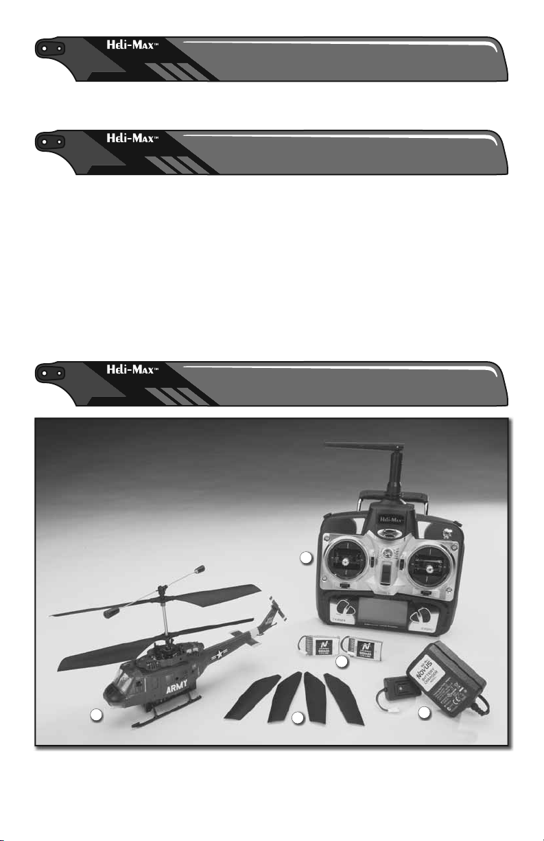
KIT CONTENTS
KIT CONTENTS
1
1. Helicopter
2. Flight Battery
3. Charger
4. Transmit ter
4
2
5
5. Replacement Main Rotor Blades
6
3
Page 7
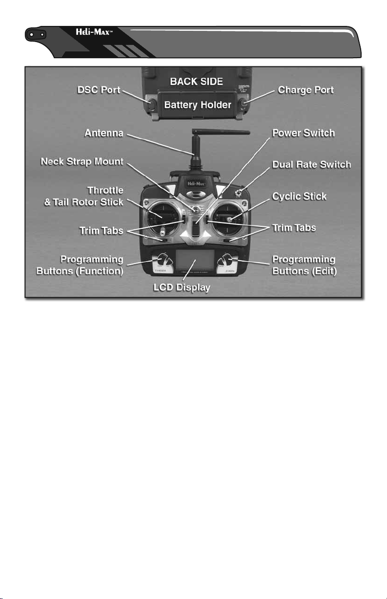
TRANSMITTER FEATURES
TRANSMITTER FEATURES
7
Page 8
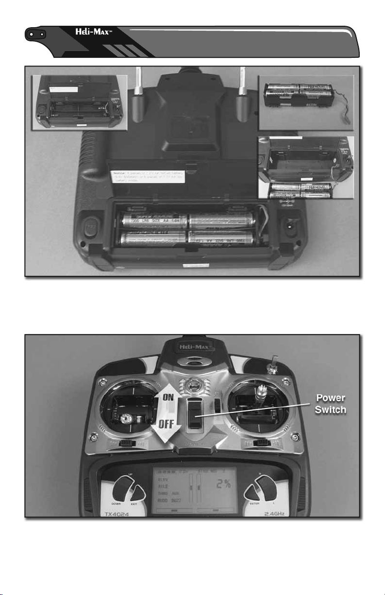
INSTALL THE TRANSMITTER BATTERIES
INSTALL THE TRANSMITTER BATTERIES
❏ Open the battery cover on the back of the transmitter, remove the battery
box and install eight AA batteries into the battery box. Double check the polarity
of each battery before placing the battery box back into the transmitter and
closing the battery cover.
❏ Turn on the transmitter and verify that the LCD initializes. Turn the transmitter
off for now. If the LCD did not initialize, remove the battery box from the
transmitter and verify that the batteries were installed correctly
8
Page 9
CHARGING THE FLIGHT BATTERY
CHARGING THE FLIGHT BATTERY
WARNING!! The charger supplied with the Heli-Max Novus Helicopter
contains protective circuitry. If you experience any diffi culties while
charging the battery, please disconnect the battery from the charger
and unplug the charger from the power source. Allow the battery
and charger to rest for two hours as this will allow the charge protection circuit
to reset. If this issue re-occurs during normal use, please contact technical
support for further assistance.
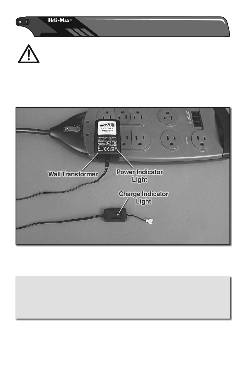
❏ Plug the wall transformer into an AC outlet. The power indicator light on the
wall transformer will be green and the charge indicator light will be solid red.
WARNING!! Do not leave the battery connected to the charger if the
charge indicator is solid red. This may over-discharge the battery, possibly
causing damage to the battery or the charger. Once the battery has been
disconnected from the charger, contact technical support immediately for
further assistance.
9
Page 10

❏ Plug the battery into the charger. The charge indicator light will start fl ashing
red quickly; this indicates that the battery is being charged. Once the battery is
completely charged, the charge indicator light will turn green (solid or fl ashing).
Disconnect the battery from the charger. Under normal operating conditions,
the battery may take up to one hour to recharge.
Charge Indicator Light
Fast Flashing Red
Green (Solid or Flashing)
*Slow Flashing Red
*Solid Red
with Battery Connected
Solid Red
without Battery Connected
The battery is being charged.
The battery is fully charged.
A time-out has occurred.
The battery voltage is too low
or the charger is not powered.
The charger is ready.
10
Once the battery
*
has been
disconnected
from the charger
contact technical
support for
further
assistance.
Page 11

LITHIUM BATTERY HANDLING & USAGE
LITHIUM BATTERY HANDLING & USAGE
WARNING! Read the entire instruction sheet included with this
battery. Failure to follow all instructions could cause permanent
damage to the battery and its surroundings, and may cause
bodily harm!
● Land your model immediately when the battery begins to lose
power. Recharge the battery before attempting another fl ight.
A dangerous situation can occur when attempting to recharge an
over-discharged battery!
● ALWAYS charge the battery inside a fi reproof container placed in a
fi reproof location clear of combustible materials. Failure to do so
can result in property damage and/or bodily harm!
● ALWAYS keep charging batteries within eyesight. Leaving the
battery unattended is dangerous!
● ALWAYS keep a supply of sand accessible when charging.
Dumping sand on the battery will extinguish the LiPo chemical fi re.
● NEVER use anything EXCEPT a LiPo approved charger.
● NEVER charge over 4.20V per cell.
● NEVER charge at currents greater than 1C.
● NEVER charge through the “To ESC” or “DISCHARGE” lead.
● NEVER trickle charge, or allow the battery to discharge below
2.75V per cell.
● NEVER allow the battery temperature to exceed 140° F [60° C].
● NEVER disassemble or modify the pack wiring in any way or
puncture cells.
● ALWAYS KEEP OUT OF REACH OF CHILDREN.
ELECTRIC MOTOR WARNING
ELECTRIC MOTOR WARNING
Electric motors are very dangerous. Do not work on the model while the fl ight
battery is plugged in as interference may cause the main rotor blades to spin,
possibly causing injury to yourself.
11
Page 12

TURNING THE MODEL ON
TURNING THE MODEL ON
❏ Place the helicopter on its side and open the battery compartment door.
Connect the fl ight battery and place the battery in the compartment as shown.
❏ Carefully place the extra wiring into the battery compartment and close the
battery door. Place the helicopter onto a fl at surface and proceed to the next step.
12
Page 13

❏ Your Novus helicopter uses a 2.4GHz system that requires linking the
transmitter to the receiver when the unit is powered up. With the transmitter
turned off, connect the fl ight battery to the helicopter. Then place the model
on a fl at surface and turn the transmitter on. You will notice that the trim tab
indicators are moving and the navigation lights on the helicopter remain solid.
This is an indication of the linking process. Allow the helicopter to remain still
and do not move the transmitter sticks during the linking process.
❏ Two loud tones will be emitted from the transmitter. Continue to allow the
helicopter to remain still. After a couple of seconds the navigation lights will
begin fl ashing rapidly. This indicates that the binding process is taking place.
The tail navigation light will stop fl ashing and the anti-collision beacon on top
of the helicopter will begin operating. This indicates that the transmitter and
helicopter have bound properly and the helicopter is now ready for fl ight. Always
step 15 feet [4.5m] away from the Novus Helicopter before operating the throttle.
Your Novus helicopter has a safe start feature built in that prevents
the motor from activating unless the collective stick has been lowered
to the lowest position. If the motor won’t run and turn the main blades,
please make sure the collective stick is all the way down and leave it
there for a couple of seconds. Then try moving the stick up slowly.
13
Page 14

TRANSMITTER CONTROLS
TRANSMITTER CONTROLS
All controls are described with the tail pointing directly toward you. This is
the best way to fl y in the beginning since it keeps the control inputs oriented
the same direction. Once you start getting comfortable you can work on side
hovering and nose-in.
The dual rate switch provides dual control rates for the cyclic and tail rotor controls.
Please use the low rate until you become accustomed to your Novus.
14
Page 15

Helicopter Moves RightHelicopter Moves Right
Helicopter Moves Right
Helicopter Moves LeftHelicopter Moves Left
Helicopter Moves Left
Moving the cyclic stick
right will cause the
helicopter to tilt right
and start moving that
direction.
Moving the cyclic stick
left will cause the
helicopter to tilt left and
start moving that
direction.
Helicopter Moves BackwardsHelicopter Moves Backwards
Helicopter Moves Backwards
15
Moving the cyclic stick
backwards (towards
you) will cause the
helicopter to tilt back-
wards and start moving
that direction.
Page 16

Helicopter Moves ForwardHelicopter Moves Forward
Helicopter Moves Forward
Helicopter ClimbsHelicopter Climbs
Helicopter Climbs
Moving the cyclic stick
forward (away from
you) will cause the
helicopter to tilt forward
and start moving that
direction.
Moving the collective
stick up (away from
you) will cause the
helicopter to climb
higher.
Helicopter DescendsHelicopter Descends
Helicopter Descends
Moving the collective
stick down (towards
you) will cause the
helicopter to descend.
16
Page 17

Nose Rotates LeftNose Rotates Left
Nose Rotates Left
Nose Rotates RightNose Rotates Right
Nose Rotates Right
Moving the tail rotor
stick towards the left
will cause the helicopter
nose to rotate left
(counterclockwise).
Moving the tail rotor
stick towards the right
will cause the helicopter
nose to rotate right
(clockwise).
17
Page 18

FLYING
FLYING
The Heli-Max Novus UH-1D Huey CX is a lightweight helicopter. Taking that into
consideration, you should only fl y indoors or in calm winds less than 1mph. The
Novus should be fl own in a large area of at least 50 feet [15.25m] square with
no obstacles.
The Novus UH-1D Huey CX is lightweight and due to this it does not fl y well in
ground effect (air disturbance when the model helicopter is hovered below 1
foot [30cm]). The model should be fl own at a minimum altitude of 1 foot [30cm]
to avoid the instabilities cause by ground effect.
Crashing
If you have operated radio control models in the past then you probably already
realize that it is not a matter of “if” you are going to crash, it is a matter of “when”
you are going to crash. Once you realize the model is going to collide with
something or crash into the ground, you should always bring the throttle stick all
the way down to stop the main rotor blades from rotating. If you can remember
to do this, chances are you will not damage the helicopter in the crash. The
main rotor blades carry a lot of RPM and inertia during fl ight. Cutting the power
to the main rotor blades will prevent most of the crash damage.
Takeoff
Slowly add power, observe the model and make all of the necessary corrections
to keep the model level. If you feel a trim adjustment is needed, lower the throttle
to idle and make trim adjustments before lifting off for the fi rst time. You will fi nd
that model helicopters never allow you to return the sticks to center. You just
need to position the stick as needed to maintain a steady hover.
You will notice the cyclic controls lag behind your inputs. This is normal and
something you get the feel for with time. It’s normal to drift around in a hover
until you become accustomed to fl ying the model. The cyclic controls are fairly
sensitive so only small movements are necessary.
Hovering
Once the helicopter is up in the air, simply try to hold the helicopter in one spot.
If this is your fi rst model helicopter, it will require some practice. Wind or air
currents have a big effect on the stability of the helicopter as well. Be patient
and slowly work forward, as trying to rush the learning process can be costly.
18
Page 19

Landing
Level the helicopter into a steady hover and slowly decrease power until the
helicopter settles onto the ground.
Basic Maneuvers
Once you become comfortable with hovering at different orientations and
landing, it’s time to move on to more advanced maneuvers.
Slow Pirouettes – Add a small amount of tail rotor (left or right) and try rotating
the helicopter slightly sideways and see if you can hold it there. If you feel
uncomfortable, then bring the tail back toward you. Once you start getting
comfortable, try moving the helicopter to the side. Then turn back and fl y back
to the other side in straight lines. Then work into rotating the helicopter around
360°, which is called a pirouette. The helicopter can drift during these so make
sure you have plenty of room when you fi rst start practicing.
Nose-in Hovering – After pirouettes it’s time to move on to nose-in hovering.
Take off and climb to 10 feet [3m]. Practice half pirouettes from tail in to nose-
in hovering and try to lengthen the delay in between. This will give you a little
practice nose-in and still give you a chance to get out of trouble. As your skills
improve you’ll remain nose-in for longer periods of time.
GOOD LUCK AND GREAT FLYING!
19
Page 20

MAINTENANCE AND REPAIR
MAINTENANCE AND REPAIR
The Heli-Max™ Novus UH-1D Huey CX is an extremely small helicopter.
Working on a model this size will require small tools. The DTXR0170 DuraTrax®
Precision Phillips Screwdriver 00x75mm is recommended. On occasion it will
be necessary to replace damaged parts after a crash. Please use this section
as a guide to performing these steps.
Main Rotor Blade Replacement
Remove the blade bolt using a #00 phillips screwdriver. After the blade bolt has
been removed, slide the rotor blade out of the blade grip. Reinstall the new blade,
ensuring that the holes within the blade and blade grip are aligned properly.
Reinstall the blade bolt.
20
Page 21

Main Rotor Grip Replacement
Remove both blade bolts and main rotor blades. If working on the upper rotor,
remove the fl ybar and linkage. The only way to remove the blade grip is to cut
the grip on both sides as shown. Remove the two halves. Remove the two metal
pivot pins from the head block. Slide the two metal pivot pins from the center of
each grip into the blade grip. Press these pins in until they are fl ush. Align the
new blade grip on the head block and from the outside of the grip. Push the pins
into the head block. Install the fl ybar and main rotor blades.
Replacing the Flybar
Remove the fl ybar linkage from the blade grip. Press outward on one side of
the head block and simply rotate the fl ybar carrier from the head block. Once
the fl ybar carrier has been removed, press the fl ybar weights inward and turn
them 90°. Now pull them off the end of the fl ybar. Remove the fl ybar linkage
from the old fl ybar and install the linkage onto the new fl ybar. Install the fl ybar
weights onto the new fl ybar and slide the fl ybar pivot back onto the head block.
Reinstall the fl ybar linkage.
21
Page 22

Replacing the Landing Gear
Remove the four landing gear screws and carefully remove the landing gear.
Route the battery lead through the new landing gear and place the landing gear
back onto the helicopter. Install the four landing gear screws.
22
Page 23

Replacing the Main Gear
The Novus Huey uses an inner solid main shaft and a hollow outer main shaft.
To access the main rotor gears it will be necessary to remove the landing gear
fi rst. Remove the lower main gear retaining screw. The lower gear will simply
drop down off the main shaft. If you need to replace the upper main gear, slide
it down off the main shaft and reinstall the new gear, ensuring that the fl at
spot molded inside the gear aligns with the main shaft. Reinstall the lower
gear, ensuring that the screw aligns with the fl at spot machined on the inner
main shaft.
Replacing the Main Shaft
The Novus CX uses an inner solid main shaft and a hollow outer main shaft.
Remove the lower main gear retaining screw. When performing the following
step please be careful not to lose any small bearings or bearing blocks. Slide the
inner shaft and upper rotor head from the outer main shaft by pulling upwards.
If you need to remove the lower shaft, disconnect the servo linkages from the
swashplate and pull upwards. Transfer necessary parts from the old shaft to the
new shaft and install following the reverse order listed above.
23
Page 24

Tail Rotor Blade Replacement
Carefully pull the tail rotor from the tail motor using your fi ngers. Press the new
tail rotor onto the shaft. Verify that the tail motor spins easily.
24
Page 25

TRANSMITTER SETTINGS
TRANSMITTER SETTINGS
Transmitter Specifi cations:
● 2.4GHz FHSS ● 4 Channel Encoder
● 100mW Output Power ● Automatic Linking
● 230mAh Current Drain
● Requires (8) AA Alkaline Batteries (Rechargeable AA cells can be used)
Stick Length Adjustment
To adjust the stick length hold onto the lower portion of the stick and turn the
upper portion counterclockwise to unlock and separate the upper stick end
from the lower stick end. Rotate the upper stick end to adjust the length. Once
you have the desired stick length set, hold onto the upper stick end to prevent
it from rotating and tighten the lower stick against the upper stick end to lock it
into position. Repeat for the other stick assembly if necessary.
25
Page 26

PROGRAMMING YOUR TRANSMITTER
PROGRAMMING YOUR TRANSMITTER
The Heli-Max TX6024 transmitter is factory set for the Novus UH-1D Huey CX
helicopter. Before making any changes it is recommended to fl y the model
several times. If you feel a change is needed after several fl ights, then please
feel free to make adjustments following the recommendations below.
WARNING! Setting these values incorrectly could result in a loss of
control, damage to the model or possibly injury to yourself or others.
Always make certain that the model is set up correctly before fl ying
the model by checking the control directions and all other settings.
Navigating & Setting Values
Always disconnect the fl ight battery from the e-board before making any
adjustments to the transmitter settings.
Press the [Enter] key to enter programming mode. You will notice that [STICK
MOD 2] is now fl ashing on the display. This is the current item being edited.
Pressing the [UP] key will take you to the previous function and pressing the
[DOWN] key will take you to the next function. Pressing the [EXIT] key will
return you back to the normal operation screen. The [UP], [DOWN] and [EXIT]
keys will not change any values so feel free to navigate the menus using these
three keys.
To make a change use the [L] or [R] keys to select the change and press
[ENTER] to set the value for the function. This is all described in the function list.
Press the [EXIT] key to return to the normal operation screen.
26
Page 27

Channel Reversing
The channel reversing function is used to reverse the operation of a servo.
Select the channel you want to reverse and press the [L] or [R] key and the
direction indication on the screen will change. To set this value you must press
the [ENTER] key before exiting this function.
Aux Channel
The AUX channel can be enabled or disabled by selecting the [ON] or [OFF]
respectively.
Buzzer Setting
Set to [OFF] to disable the internal speaker. Set to [ON] to enable the internal
speaker.
Novus UH-1D Huey Default Settings
STICK MOD
ELEV
AILE
THRO
RUDD
AUX
BUZZ
2
NOR
REV
NOR
REV
OFF
ON
27
Page 28

E-BOARD ADJUSTMENTS
E-BOARD ADJUSTMENTS
Gyro Gain
The gyro gain is used to adjust the amount of correction that the gyro applies
to the tail rotor during unintended movements. Finding the ideal gain setting
will take some experimentation. If the gyro is allowing the tail to drift, then raise
the gain % and test fl y the model. If the tail is quickly oscillating (wagging),
then lower the gain % and test fl y the model. Turning the adjustment clockwise
increases the gain and turning the adjustment counter clockwise decreases
the gain.
28
Page 29

ORDERING PARTS
ORDERING PARTS
Replacement parts for the Heli-Max Novus UH-1D Huey CX are available using
the order numbers in the Replacement Parts List that follows. The fastest,
most economical service can be provided by your hobby dealer.
To locate a hobby dealer, visit the Hobbico web site at www.hobbico.com.
Choose “Where to Buy” at the bottom of the menu on the left side of the page.
Follow the instructions provided on the page to locate a U.S., Canadian or
International dealer.
Parts may also be ordered directly from Hobby Services by calling (217) 3980007, or via facsimile at (217) 398-7721, but full retail prices and shipping and
handling charges will apply. Illinois and Nevada residents will also be charged
sales tax. If ordering via fax, include a Visa® or MasterCard® number and
expiration date for payment.
Mail parts orders and payments by personal check to:
Hobby Services
3002 N. Apollo Drive, Suite 1
Champaign, IL 61822
Be certain to specify the order number exactly as listed in the Replacement
Parts List. Payment by credit card or personal check only; no C.O.D.
If additional assistance is required for any reason contact Product Support by
e-mail at helihotline@hobbico.com, or by telephone at (217) 398-8970.
29
Page 30

EXPLODED VIEW & PARTS LIST
EXPLODED VIEW & PARTS LIST
2
2
8
1
6
3
9
1
11
21
13
18
3
3
16
5
7
5
21
3
2
3
6
6
21
1
1
21
16
18
18
14
14
14
14
16
12
30
Page 31

Part # Description
1 HMXE8297 Main Rotor Blades
2 HMXE8536 Flybar Assembly
3 HMXE8537 Main Blade Grips (2)
4 HMXE8458 Tail Rotor Blade
5 HMXE8574 Locking Sleeve Assembly
6 HMXE8573 Rotor Head Linkage Set
7 HMXE8539 Outer Main Shaft
8 HMXE8540 Inner Main Shaft
9 HMXE8541 Lower Head Block/Blade Drive
10 HMXE7417 Replacement Fuselage
11 HMXE8542 Swashplate Assembly
12 HMXE8040 Main Drive Gears
Part # Description
13 HMXE7894 Swashplate Autorotation
Frame
14 HMXE7895 Main Frame
15 HMXE7896 Landing Gear/Battery
Mount
16 HMXE8835 Ball Bearing Set
17 HMXE7336 Complete Screw Set
18 HMXG8024 Replacement Motor Set
19 GPMP0410 Battery (3.7V 600mAh)
20 HMXP2019 1S LiPo Charger
21 HMXM2019 E-Board Assembly
22 HMXJ2028 4Ch 2.4 GHz Transmitter
10
10
10
10
10
10
10
15
Optional Upgrades
17
19
HMXE7468 CNC Main Blade Grips Upper and Lower
HMXE7469 Outer Shaft w CNC Retainer Collar
15
HMXE7470 CNC Head Block W Inner Rotor Shaft
10
10
4
10
10
HMXE7471 CNC Swashplate Assembly
GPMM3150 Charge Lead Banana to HMX Micro Plug
HMXE7477 CNC Head Conversion
31
Page 32

 Loading...