

Page 1
READ THROUGH THIS INSTRUCTION MANUAL
FIRST. IT CONTAINS IMPORTANT INSTRUCTIONS
AND WARNINGS CONCERNING THE ASSEMBLY
AND USE OF THIS MODEL.
HMXZ7013 for HMXE0250 V1.1Entire Contents © Copyright 2007
Champaign, Illinois
(217) 398-8970, Extension 6
E-mail: helihotline@hobbico.com
INSTRUCTION MANUAL
TM
Heli-Max™guarantees this kit to be free from defects in both
materials and workmanship at the date of purchase. This
warranty does not cover any component parts damaged by use
or modification.In no case shall Heli-Max’s liability exceed the
original cost of the purchased kit. Fur ther, Heli-Max reserves
the right to change or modify this warranty without notice.
In that Heli-Max has no control over the final assembly or material
used for final assembly, no liability shall be assumed nor accepted
for any damage resulting from the use by the user of the final
user-assembled product. By the act of using the user-assembled
product, the user accepts all resulting liability.
If the buyer is not prepared to accept the liability associated
with the use of this product, the buyer is advised to return
this kit immediately in new and unused condition to the place
of purchase.
To make a warranty claim, send the defective part or item to
Hobby Services at this address.
Hobby Services
3002 N. Apollo Dr., Suite 1
Champaign, IL 61822
USA
Include a letter stating your name, return shipping address, as
much contact information as possible (daytime telephone
number, f ax number, e-mail address), a detailed description of the
problem and a photocopy of the purchase receipt.Upon receipt of
the package the problem will be evaluated as quickly as possible.
WARRANTY
Rotor Span: 52.75 in [1340mm]
Weight: 7.5 lb [3402g]
Length: 47 in [1194mm]
Height: 15.25 in [387mm]
Engine: .46-.51 cu in [7.5-8cc] 2-Stroke
Gear Ratio: 9.1:1 (Main)
5:1 (Tail)
TM
Page 2

2
INTRODUCTION ..............................................................2
SAFETY PRECAUTIONS ................................................3
DECISIONS YOU MUST MAKE........................................4
ADDITIONAL ITEMS REQUIRED ....................................4
Required Hardware ..........................................................4
Field Equipment ................................................................4
Optional Supplies and Tools..............................................4
IMPORTANT BUILDING NOTES......................................5
KIT INSPECTION..............................................................5
KIT CONTENTS................................................................5
ASSEMBLY INSTRUCTIONS ..........................................6
Lower Frame and Tank......................................................6
Engine ..............................................................................6
Upper Frame and Servo Frame Installation ......................8
Main Rotor Head Assembly and Installation ....................9
Tail Boom and Gearbox Assembly..................................11
Tail Blades ......................................................................12
Horizontal and Ver tical Fins ............................................12
Tail Boom Suppor ts ........................................................13
Landing Gear ..................................................................14
Gyro Mount and Tail Rotor Servo Mount ........................14
Horizontal Fin Alignment ................................................15
EQUIPMENT INSTALLATION ........................................15
Servos and Power Switch................................................15
Battery, Receiver and Gyro ............................................16
Receiver Antenna............................................................17
Receiver Channel Assignment Table ..............................17
Connecting the Servos to the Receiver ..........................17
RADIO SETUP (FUTABA: 6EXH,7CH,9CH)..................18
Setup Quick Reference ..................................................18
Transmitter Preparation ..................................................18
Reset Model Memory......................................................18
Set Modulation Type........................................................19
Model Name....................................................................19
Exponential......................................................................19
Servo Reversing..............................................................20
End Point Adjustments....................................................21
Sub-Trim ..........................................................................21
Fail Safe ..........................................................................21
Gyro Function..................................................................21
Throttle Cut......................................................................22
Hover and Throttle Trims ................................................22
Hi-Lo Pitch Trims ............................................................22
Throttle Curve..................................................................22
Pitch Curve......................................................................23
Intermediate and Basic Aerobatic Curves ......................23
Advanced 3D and Aerobatic Curves ..............................23
SERVO SETUP AND LINKAGES ..................................24
Forward/Aft Cyclic Setup ................................................24
Left/Right Cyclic Setup....................................................24
Collective Pitch Setup......................................................25
Throttle Setup..................................................................26
Tail Rotor Ser vo ..............................................................26
Gyro Setup ......................................................................27
HEAD AND LINKAGES..................................................27
Install Main Rotor Head Linkages ..................................27
Main Blades ....................................................................27
Blade Balancing ..............................................................28
Pitch Curves....................................................................29
FINAL ASSEMBLY ........................................................30
Fuel Lines........................................................................30
Muffler Installation ..........................................................30
Body ................................................................................30
Decals..............................................................................31
PREPARE FOR FLIGHT ................................................32
Check the Control Directions ..........................................32
Range Check ..................................................................34
Balance the Model (C.G.)................................................34
PREFLIGHT ....................................................................34
Identify Your Model ..........................................................34
Charge the Batteries ......................................................34
AMA SAFETY CODE (Excerpts) ..................................34
FLYING............................................................................35
Training Gear ..................................................................36
Flying Conditions ............................................................36
Before Each Flight ..........................................................36
Starting the Model ..........................................................36
Adjust Blade Tracking......................................................36
Takeoff ............................................................................37
Hovering..........................................................................37
Landing............................................................................37
Basic Maneuvers ............................................................37
Aerobatics........................................................................37
PARTS LIST....................................................................38
Ordering Parts ................................................................38
Exploded Views ..............................................................39
Thank you for purchasing the Heli-Max™Kinetic™.50. We
are certain you will get many hours of enjoyment out of this
model.If you should ha v e an y questions or concerns please
feel free to contact us at:
helihotline@hobbico.com
For the latest technical updates or manual corrections to the
Kinetic .50 visit the Heli-Max web site at:
www.helimax-rc.com
Open the “Helicopters” link, and then select the Kinetic .50. If
there is new technical information or changes to this model a
“tech notice”bo x will appear in the upper left corner of the page.
INTRODUCTION
TABLE OF CONTENTS
Page 3
3
For any helicopter to perform to its full potential, it must be
equipped with all the right gear (servos, batteries, receiver , etc).
While other brands of equipment can be used, the equipment
we recommend has the advantage of being extensively tested
and proven effective. If you assemble this model according to
this manual and use the recommended equipment, you should
get top performance from your Kinetic .50.
We urge you to join the AMA (Academy of Model Aeronautics)
and a local R/C club.The AMA is the governing body of model
aviation and membership is required to fly at AMA clubs.
Though joining the AMA provides many benefits, one of the
primary reasons to join is liability protection. Coverage is not
limited to flying at contests or on the club field. It even applies
to flying at public demonstrations and air shows. Failure to
comply with the Safety Code (excerpts printed in the back of
the manual) may endanger insurance coverage. Additionally,
training programs and instructors are available at AMA club
sites to help you get started the right way .There are over 2,500
AMA chartered clubs across the countr y.Contact the AMA at
the address or toll-free phone number below.
Failure to follow these safety precautions may result in
severe injury to yourself and others.
• Keep your face and body as well as all spectators away
from the plane of rotation of the rotors.
• Keep these items away from the rotors: loose clothing
(includes ties, scarfs and shirt sleeves), long hair, and
loose objects (such as pencils, screwdrivers) which can f all
from shirt or jacket pockets.
• The spinning blades of a model helicopter can cause
serious injury. Main rotor blades are consumable items,
please inspect blades before flight.
• When choosing a flying site for your Kinetic .50, stay clear
of buildings, trees and power lines.
• AVOID flying in or near crowded areas. DO NOT fly close
to other people, children or pets.
• Maintain a safe pilot-to-helicopter distance while flying.
• Your Kinetic .50 should not be considered a toy, but rather
a sophisticated, working model that functions very much
like a full-size helicopter. Because of its performance
capabilities, the Kinetic .50, if not assembled and operated
correctly, could possibly cause serious injury to you or
spectators and damage to property.
• You must assemble the model according to the
instructions. Do not alter or modify the model, as doing
so may result in an unsafe or unflyable model. In a few
cases the instructions may differ slightly from the photos.
In those instances, the written instructions should be
considered as correct.
• You must take time to build properly, true and strong.
• You must use an R/C radio system that is in first-class
condition and a correctly sized engine and components
throughout the building process.
• You must correctly install all R/C and other components so
that the model operates correctly on the ground and in the air .
• You must check the operation of the model before every
flight to insure that all equipment is operating and that the
model has remained structurally sound. Be sure to check
linkages or other connectors often and replace them if they
show any signs of wear or fatigue.
• If you are not an experienced pilot or have not flown this
type of model before, we recommend that you get the
assistance of an experienced pilot in your R/C club for y our
first flights. If you’re not a member of a club, your local
hobby shop has information about clubs in your area
whose membership includes experienced pilots.
SAFETY PRECAUTIONS
Two of the most important things you can do to
preserve the radio controlled aircraft hobby are to
avoid flying near full-scale aircraft and avoid flying
near or over groups of people.
Academy of Model Aeronautics
5151 East Memorial Drive
Muncie, IN 47302
Tele: (800) 435-9262
Fax (765) 741-0057
Or via the Internet at:
http://www.modelaircraft.org
AMA
CAUTION: Be aware that the Kinetic .50 is
operated on the same frequency band as most R/C
models. If flying your helicopter within five miles of an
R/C site, there is a real possibility that you could be
operating your model on the same frequency (channel)
as another R/C pilot. If this happens, a crash will
result—with the person flying the more expensive
model suffering the greater loss (and having greater
potential for property damage or injury). The best thing
to do is to join an R/C club and fly at the site where
frequency control measures will be in effect.If you insist
on flying elsewhere, always be aware of your proximity
to R/C flying sites.
Page 4

4
Remember: Take your time and follow the instructions
to build a safe and enjoyable model.
This is a partial list of items required to finish the Kinetic .50
that may require planning or decision making before starting
to build. Order numbers are provided in parentheses.
The Kinetic .50 requires five servos.The cyclics, throttle and
collective require a minimum of 42 oz/in for basic aerobatics.
A Hi-Speed and Hi-Torque tail servo such as the (FUTM0224)
Futaba®DS9254 is highly recommended to obtain the best
performance from the gyro.
A 6-channel transmitter is required to fly the Kinetic .50.
Modern computer radios make adjustments considerably
easier and are highly recommended. Plus the features on
the radios today make 3D maneuvers possible.
Transmitter/Receiver Recommendations:
• Budget: Futaba 6EXH FM w/4 S3151 Servo (FUTK58**)
• Mid-Range: Futaba 7CHF FM w/4 S3151 Servos (FUTJ73**)
• High-End: Futaba 9CHPS PCM Synthesized (FUTK9205)
Recommended Cyclic,Throttle and Collective Servos:
• Budget: Futaba S3001 (FUTM0029)
• Mid-Range: Futaba Digital S3151 (FUTM0310)
• High-End: Futaba Digital S9252 (FUTM0222)
Recommended Gyro and Tail Servo:
• Budget: Futaba GY240 (FUTM0809) and
S3151 Servo (FUTM0310)
• Mid-Range: Futaba GY401 w/S9254 Servo (FUTM0808)
• High-End: Futaba GY611 w/S9256 Servo (FUTM0825)
Recommended Receiver Batteries:
A 4-cell, 4.8 volt (2000mAh minimum) NIMH/NICAD battery
pack is recommended for the Kinetic .50
• Hydrimax™4.8volt 2000mah Flat Battery (HCAM6321)
• Hydrimax 4.8volt 3600mah Flat Battery (HCAM6333)
• Hydrimax 4.8volt 4200mah Flat Battery (HCAM6335)
REQUIRED HARDWARE AND ACCESSORIES
This is the list of hardware and accessories required to finish
the Kinetic .50. Order numbers are provided in parentheses.
❏ O.S.
®
50 SX-H Ringed Hyper (OSMG1951)
❏ Tor pedo Muffler .46-.50 (CEHG3033)
❏ Great Planes
®
Pro Thread Locker (GPMR6060)
❏ Great Planes 1" x 3' Double Sided Tape (GPMQ4442)
❏ Great Planes 3' Silicone Fuel Tubing (GPMR4131)
❏ Great Planes Fuel Filter (GPMQ4150)
❏ O.S.Remote Glow Plug Adapter (OSMG2401)
❏ Heli-Max .30 – .50 Size Blade Holder (GPMQ4150)
FIELD EQUIPMENT
❏ Heli-Max One-Way Start Shaft (HMXP2050)
❏ Hobbico
®
Glow Plug Wrench (HCAP2550)
❏ Hobbico Ultra-Tote
™
Field Box Complete Combo
(HCAP5105) (Includes the following items):
• Filling Station Can Fittings Set (GPMP4155)
• 12V Charger Torqmaster™Battery (HCAP0200)
• Deluxe Power Panel II (HCAP0302)
• Torqmaster 12V 7A Batter y (HCAP0800)
• 5' Recoil Fuel Tubing (HCAP2200)
• Panel-Ready Locking Glow Plug Clip (HCAP2502)
• Panel-Ready Top Fueler™6/12 V olt (HCAP3107)
• Torqmaster 90 12V Star ter (HCAP3200)
• Ultra-Tote Field Box (HCAP5020)
OPTIONAL SUPPLIES AND TOOLS
❏ O.S.Crankshaft Clamp .32-.46 (OSMR1004)
❏ DuraTrax
®
Phillips Screwdriver (DTXR0181)
❏ DuraTrax Slotted Screwdriver (DTXR0177)
❏ Hobbico Needle Nose Pliers (HCAR0625)
❏ Hobbico Curved Scissors (HCAR0667)
❏ Heli-Max Ball Link Pliers (HMXR4858)
❏ Heli-Max Pitch Gauge (HMXR4850)
❏ Heli-Max Blade Balancer (HMXR4855)
❏ DuraTrax 5.5mm Nut Driver (DTXR0212)
ADDITIONAL ITEMS REQUIRED
DECISIONS YOU MUST MAKE
We, as the manufacturer, provide you with a
top quality, thoroughly tested ARF and instructions,
but ultimately the quality and flyability of your finished
model depends on how you build it; therefore, we
cannot in any way guar antee the performance of your
completed model, and no representations are
expressed or implied as to the performance or safety
of your completed model.
Page 5
5
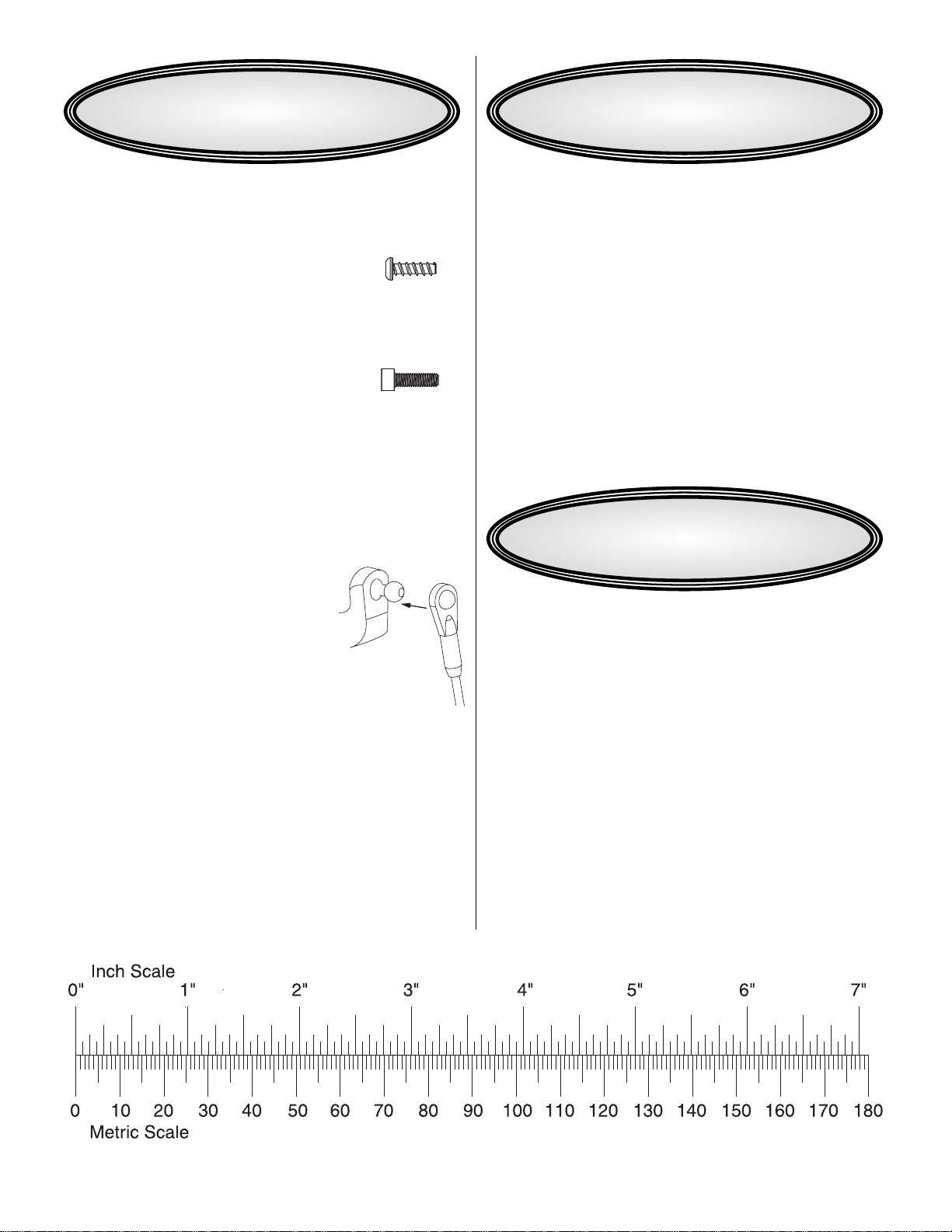
• There are two types of threaded fasteners used in this kit:
Self-T apping Screwsare designated by a diameter and
a length and are intended to thread into plastic.
This is a 3mm x 10mm Self-Tapping
Machine screws are designated by a diameter and
threads per mm/inch. This type of screw is referred to as
Socket Head Cap Screw (SHCS) through out this man ual.
This is a 3mm x 10mm SHCS
• Thread Locker: Model engines generate a lot of vibration
and cause screws to work loose.Thread Locker (GPMR6060)
should be used on all machine screws when they are
threaded into a pre-tapped hole in metal. Generally blue
thread locker is removable and should be used in all cases.
Please keep in mind only a small amount of thread locker is
needed to retain the bolt. Please check preassembled
components for thread locking compound.
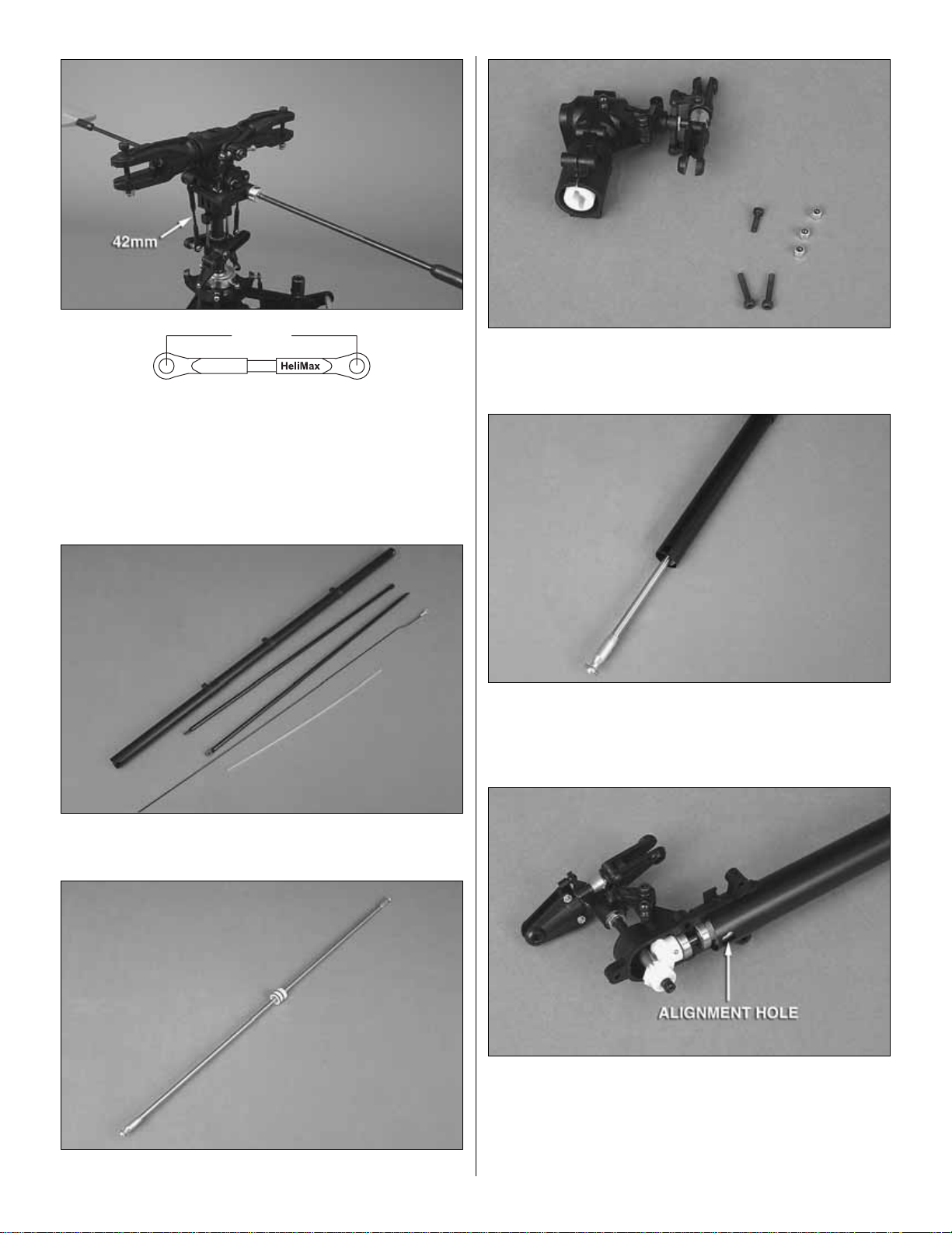
• Ball Links: If you look closely at the
plastic ball links used on this helicopter
you will notice the holes on each side of
the link are different sizes.The side with
the smaller hole also has writing on it as shown above.
When you snap the link on, make sure the writing is to
the outside. If you accidentally snap the small side on
first, the ball link may crack. If the ball link does not pivot
freely once snapped on, you can use a small pair of pliers
to lightly squeeze the link and help loosen it up.
• When you see the term
test fit
in the instructions, it means
that you should first position the part on the assembly to
verify it fits properly. Once you are sure, then proceed with
the instructions or assembly.
• Photos and sketches are placed before the step they
refer to .Frequently you can study photos in following steps
to get another view of the same parts.
Before starting to build, take an inventory of the model to
make sure it is complete, and inspect the parts to make sure
they are of acceptable quality. If any parts are missing or are
not of acceptable quality, or if you need assistance with
assembly, contact Product Support.When reporting defective
or missing parts, use the part names exactly as they are
written in the Kit Contents list.
Heli-Max Product Support:
3002 N. Apollo Drive, Suite 1,
Champaign, IL 61822
Telephone: (217) 398-8970, ext.6,
Fax:(217) 398-7721
E-mail: helihotline@hobbico.com
Bag 1: Head Parts and Paddles
Bag 2: Main Mechanics
Bag 3: Clutch System and Fan
Bag 4: Links, Gyro and Tail Servo Mounts
Bag 5: Fin Set
Bag 6: Landing Gear Set
Bag 7: Main Blades
Bag 8:Tail Boom
Bag 9: Servo Tray Set
Bag 10: Lower Frames, Fuel Tank, Fan Shroud
Bag 11: Canopy
KIT CONTENTS
KIT INSPECTIONIMPORTANT BUILDING NOTES
H
e
l
iM
a
x
Page 6
6
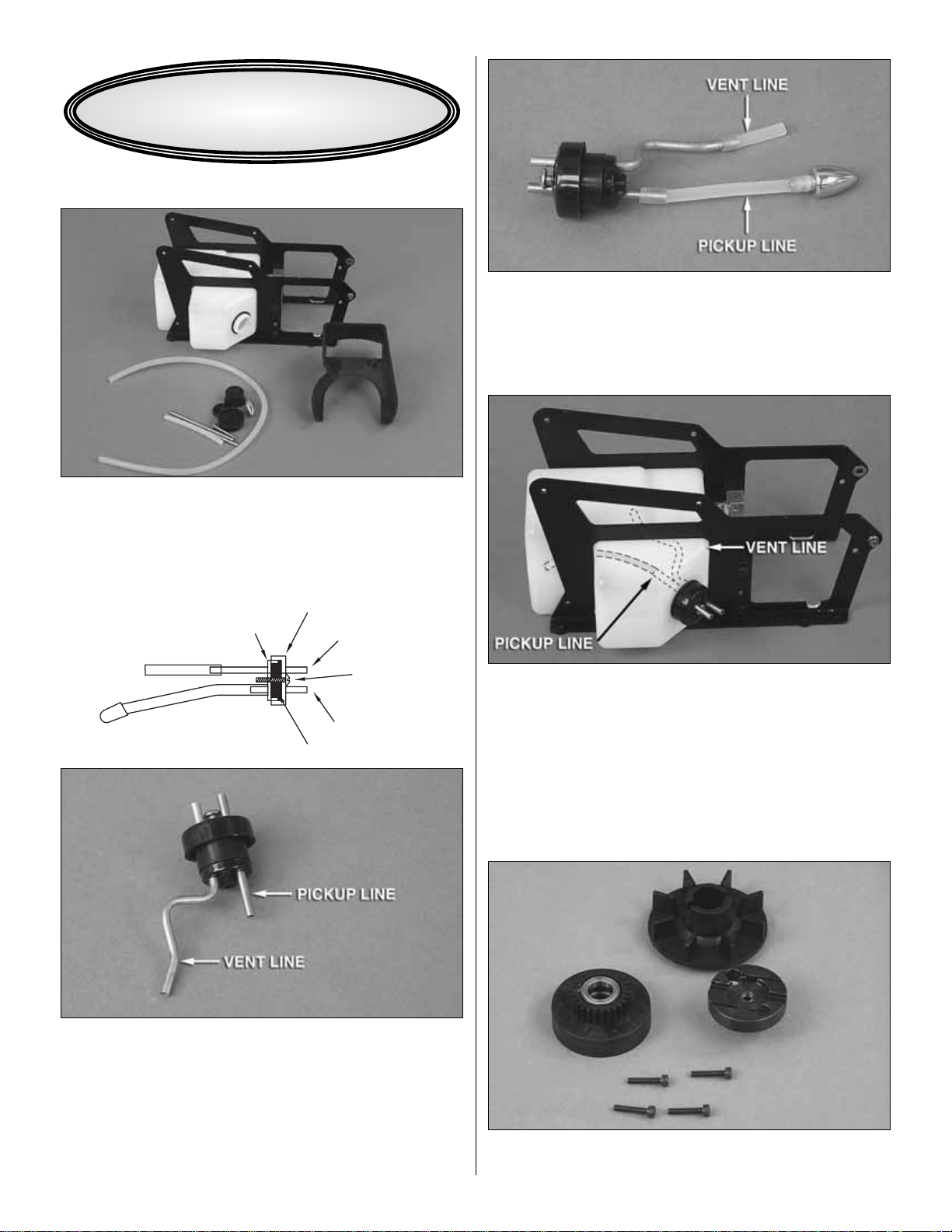
LOWER FRAME AND TANK
Bag 10 Contents: Main Frame Assembly (Engine Mount
and Fuel Tank Installed), Fuel Stopper, Brass Tubing,
Silicone Fuel Line, and Stopper Screw, Lower Fan Shroud.
❏ 1. Slide the short brass tubing through the front cap. Slide
the rubber fuel tank stopper over the brass tubing from the
back side.Install the rear cap. Insert the long pre-bent piece of
brass tubing through the rear cap and through the rubber
stopper.Leave 1/2" [12.7mm] of brass tubing protruding from
the front of the cap.Install the 4mm self-tapping screw through
the front cap and into the rear cap (Start the screw into the
cap.Do not tighten until it has been installed into the fuel tank).
❏ 2. Cut the clunk line to a length of 60mm and slide it onto
the short brass tubing.Slide the fuel tubing ov er the clunk.Cut
a piece of the larger silicone tubing to 30mm with an angled
cut as shown above. Install on the vent line. Hint: Use a
marker to identify the pickup line later.
❏ 3. Rotate the vent line against the pickup line to make it
easier to install. Slide the fuel line assembly into the fuel
tank and align the vent line with the top of the tank (if you
find it difficult to see inside the tank, hold it up to a bright
light).Tighten the 4mm fuel tank stopper screw until you feel
it begin to compress. Do not overtighten this as you may
strip the rear cap.
ENGINE
Bag 3 Contents: Clutch Bell, Fan, Clutch, Engine Mount
From Bag 10: Screws (3x16mm Socket Head Cap Screw)
AS VIEWED FROM THE TOP
REAR CAP
FRONT CAP
VENT
4mm SCREW
FUEL PICKUP LINE
RUBBER STOPPER
ASSEMBLY INSTRUCTIONS
Page 7
7
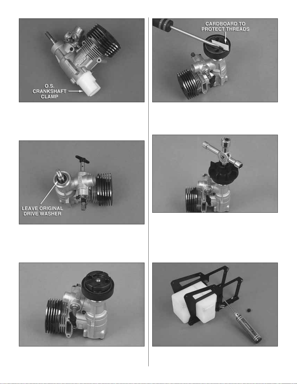
Note: You will need to lock the crankshaft while tightening
the clutch and nut.We recommend using a O.S.Crankshaft
Clamp .32-.46 (OSMR1004) as shown above.
❏ 1.Remove the n ut from the end of the engine’s crankshaft
but leave the large flat washer resting against the front ball
bearing. The large washer (10x16mm) included in the kit is
only used if your engine did not include one.
❏ 2. Slide the clutch bell onto the stepped end of the clutch
and test fit the assembly on the engine. Once you verify
everything threads on properly, remove the clutch and bell.
❏ 3. Apply thread lock to the crankshaft of the engine and
thread the clutch onto the engine. Use a thick piece of
cardboard to protect the crankshaft and tighten the clutch
using a screwdriver as shown in the picture above.
❏ 4. Install the fan on the engine. Make sure the key on the
bottom of the fan lines up with the slots in the clutch. Place
the 6.5x13mm washer on the crankshaft, apply some thread
lock to the crankshaft threads and install the original
crankshaft nut.Using a crankshaft clamp and a 7/16" [11mm]
wrench, tighten the nut down against the fan. Re-install the
engine’s backplate.
❏ 5.Using a 2.5mm hex driver remove the two engine mount
bolts from the right side of the frame. Remove the right side
frame and fuel tank for now.
Page 8
❏ 6. Install the engine onto the mount using thread locker
and the four 3x16mm screws provided.
❏ 7.Install the right side frame using the 3x12mm screws and
large washers (use thread lock). Before tightening the bolts
place the frames on a flat surface to ensure they are parallel.
Tighten the bolts. Check the left side engine mount bolts
(factory-assembled) for thread locker and apply if necessary.
UPPER FRAME AND SERVO FRAME INSTALLATION
Bag 2 Contents: Assembled Main Mechanics
Bag 9 Contents: Servo Tray Set, 3x12mm Cap Screw (4),
3x8mm Self-Tapping Screw (2), 3x8mm Mashine Screw (2),
3x8x1mm Flat Washer (4), 3x12mm Self-Tapping Screw
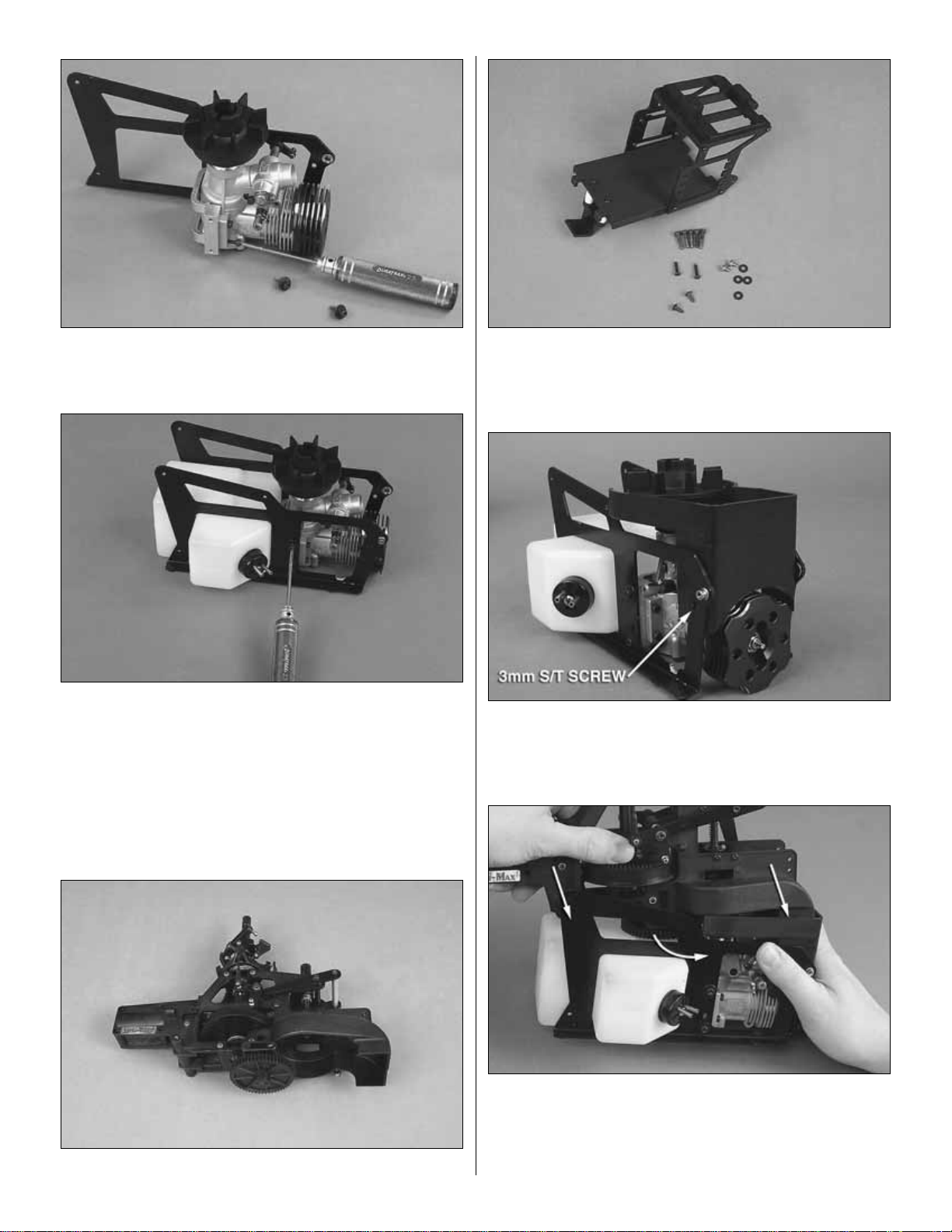
❏ 1. Slide the lower fan shroud over the engine as shown in
the picture above and install the 3mm self-tapping screw as
shown. Repeat on the opposite side.
❏ 2. Slide the rear portion of the upper frame into the lower
frame. Align the upper and lower fan shroud and slide the
upper frame forward while pressing downward. The clutch
bell and pinion must clear the main gear before the upper
frame will slide down into its proper location.
8
Page 9
9
❏ 3. Apply thread locker to one 3x12mm socket head cap
screw. Install the screw and washer as shown above.
Repeat on the opposite side of the frame.
❏ 4. Apply thread locker to one 3x14mm socket head cap
screw .Install the screw and washer as shown above.Repeat
on the opposite side of the frame.
❏ 5. Slide the servo frame in-between the lower frames and
onto the upper frames. Install a 3x12mm self-tapping screw
into the top of the frame as shown above. Repeat for the
opposite side.
❏ 6. Install the silver 3x6mm silver Phillips screw into the
lower part of the servo frame as shown above. Remove the
two bellcrank to swash linkages and verify they are 51mm
long. Go ahead and re-install the linkages now.
MAIN ROTOR HEAD ASSEMBLY AND INSTALLATION
Bag 1 Contents: Flybar Control Arm [4x6x2.5mm Plastic
Spacer (2), Washout-Flybar Pushrod (2), Flybar Control
Arm (2), 5x4mm Set Screw], Flybar Paddles [Flybar Weights
(2), 3x3mm Set Screws (2), Flybar Paddles .50 Sized (2)],
Main Head Assembly, 4x30mm Cap Screw (2), 4mm
Locknut (2), 3x20mm Cap Screw, 3mm Locknut
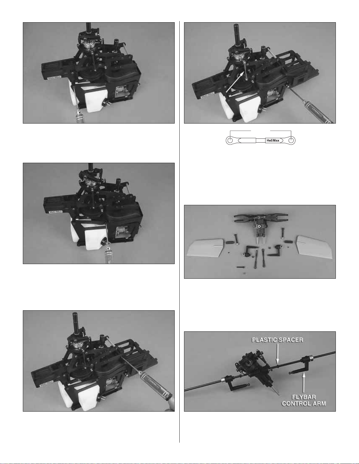
❏ 1. Slide the 4mm flybar (found in tail boom bag 8) through
the flybar carrier bearings and slide a plastic bushing on from
each side.Next slide the control arms onto the flybar as shown
in the picture above.(The set screws will face upwards.)
51mm
(Sketch not to scale)
Page 10
❏ 2.Remo v e the set screws from the flybar arms and align the
hole with the flat spot on the flybar. Apply a small amount of
thread locker to each of the set screws and re-install.Only lightly
tighten them at this time as the flybar needs to be centered.
❏ 3. Using a ruler, center the flybar as shown above. The
measurement should be approximately 181mm for each side .
❏ 4. Once the flybar is centered, tighten the flybar arm
set screws.
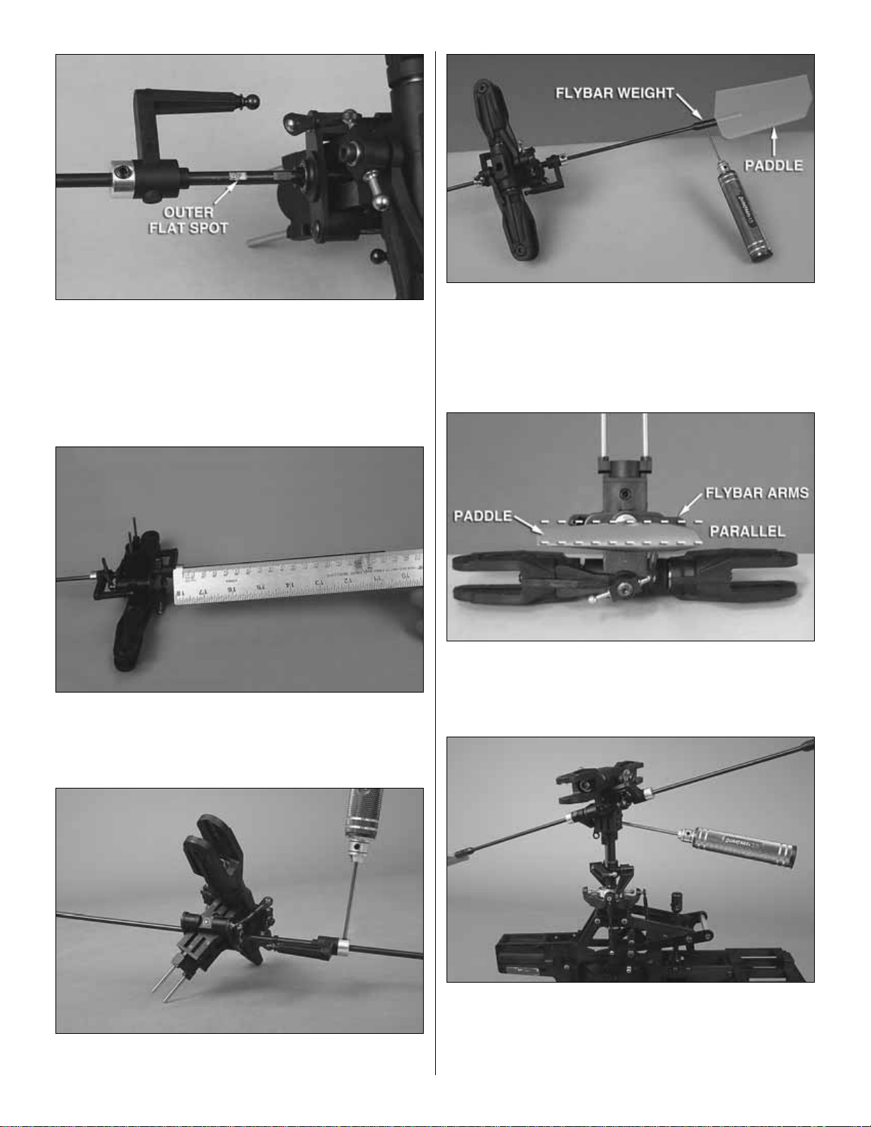
❏ 5. Install the two 3x3mm set screws into the flybar
weights. Slide the weights onto the flybar with the beveled
end facing inward. Thread the paddles onto the flybar at
least 1" [25.4mm]. Measure from the outside of the flybar
arm to the beginning of the paddle. Make sure both paddles
are the same distance out and facing forward as shown.
❏ 6. Align the paddle with the flybar control arms as shown
above. The paddles and arms must be parallel. Slide the
flybar weights all the way out against the paddles and tighten
the set screws.
❏ 7. Slide the head onto the main shaft and align the bolt hole
in the head block with the hole in the main shaft.To help align
the two holes, insert a 2.0mm hex driver into the hole.Insert the
3x16mm SHCS through the head block and main shaft.Place a
3mm nylon lock nut on the opposite side and tighten the bolt.
10
Page 11
11
❏ 8.Chec k the two linkages and v erify they are 42mm.Install
the two linkages onto the flybar control arm and the washout
arm as shown above.Temporarily install the 4mm main blade
bolts into the blade grips.Do not tighten at this time.
TAIL BOOM AND GEARBOX ASSEMBLY
Bag 8 Contents: Tail Boom, Tail Boom Supports, Tail Rotor
Pushrod, Antenna Tube
Bag 8-1 Contents: Torque Tube
Bag 8-2 Contents: 3x16mm SHCS, 3x10mm SHCS, 3mm
Nylon Lock Nuts
❏ 1.Insert the torque tube into the tail boom. If the O-rings
do not slide easily, apply a small amount of dishwashing
soap to the O-rings.
❏ 2. Remove the left side of the tail rotor gearbox and insert
the right side into the boom as shown above. Please notice
there are two holes on one end of the tail boom.This is the end
where the tail gearbox attaches.Make sure the alignment tab
molded in the tail rotor gearbox halves line up with the hole in
the tail boom. Install the left side of the tail rotor gearbox.
42mm
(Sketch not to scale)
Page 12
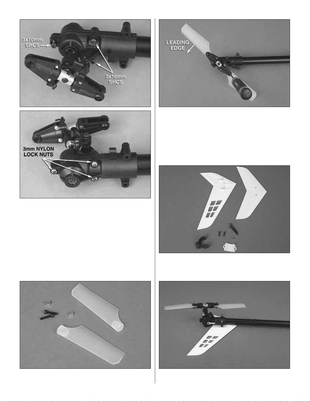
❏ 3. Install three 3mm nylon lock nuts on the back side of
the gearbox where you just inserted the 3mm screws.
Tighten the bolts.
TAIL BLADES
Bag 5-1 Contents:
Tail Rotor Blades, 3x16mm Cap Screw
(2), M3 Locknut (2), Fiber Filled Tail Blades 85mm (2)
❏ Install the plastic tail blades as shown above using a
3x16mm SHCS and 3mm Nylon lock nuts.Tighten until the
blades will support their own weight. Both tail blades need
to be tightened equally.
HORIZONTAL AND VERTICAL FINS
Bag 5 Contents: Horizontal Tail Fin, Vertical Fin, Horizontal
Fin Mount, Horizontal Mounting Plate, 3x30mm Cap Screw,
3x11mm Self-Tapping Screw, 3mm Locknut
❏ 1. Using two 3x30mm screws and 3mm nylon lock nuts,
attach the vertical fin to the tail rotor gearbox as shown abov e.
12
Page 13
13
❏ 2. Install the horizontal fin clamp.Using two 3x16mm self-
tapping screws, attach the horizontal fin to the clamp .Do not
completely tighten bolts at this time as you will need to adjust
the position in a later step.
❏ 3.Slide the tail boom into the main frame as shown.It will be
necessary to turn the main rotor head while pushing forward on
the boom to help align the tail drive system.The frame screws
used to clamp the boom are installed in a later step.
TAIL BOOM SUPPORTS
Bag 8-3 Contents: 3x10mm SHCS, 3mm Self-Tapping
Screws, Plastic Spacers, 3mm Nylon Lock Nuts
❏ 1.Install the boom supports using two 3x10mm SHCS and
two 3mm nylon lock nuts .You will need a pair of small needle
nose pliers for this step.
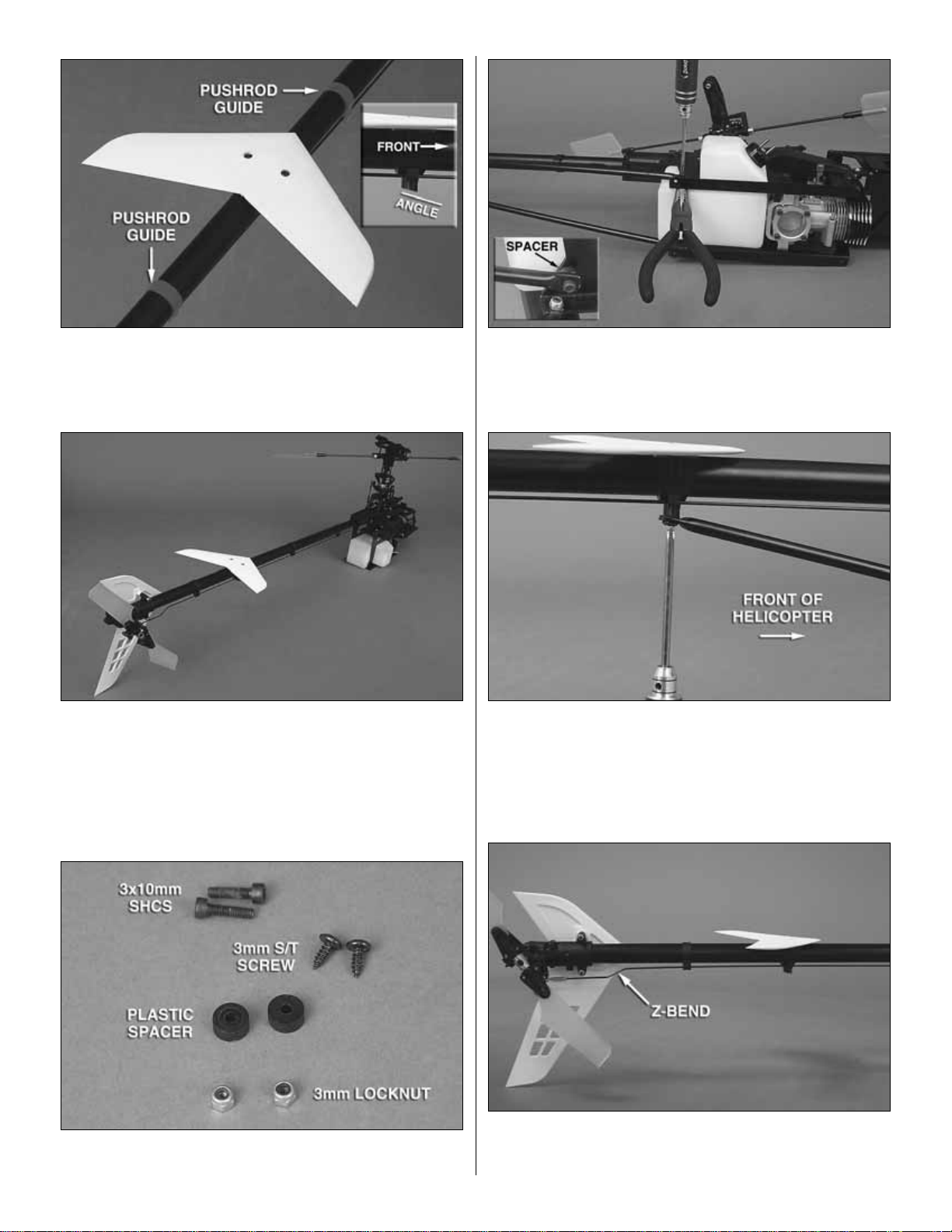
❏ 2. Install the two 3x8mm self-tapping screws.Use a drop
of CA on the screw to prevent it from coming loose. Please
notice that the angle molded on the bottom of the fin clamp
angles down and toward the front of the helicopter.
❏ 3. Slide the tail rotor pushrod through the guides and
horizontal fin clamp.The Z-bend lines up vertically as shown in
the picture.Snap the plastic ball link onto the tail rotor bellcrank.
Page 14
LANDING GEAR
Bag 6 Contents: 3x20mm SHCS (4), Plastic Spacers,
3mm Nylon Lock Nut (4), 3x4mm Set Screws (4)
❏ 1. Inser t a 3x20mm SHCS through the underside of the
landing gear strut. Slide a plastic spacer on the top and
insert the screw into the front frame hole. From the top,
install a 3mm nylon lock nut and tighten the bolt.Repeat for
the other side and the rear strut. If the front skid does not
clear the cylinder head on your engine, then simply mount
the front skid in the aft hole.
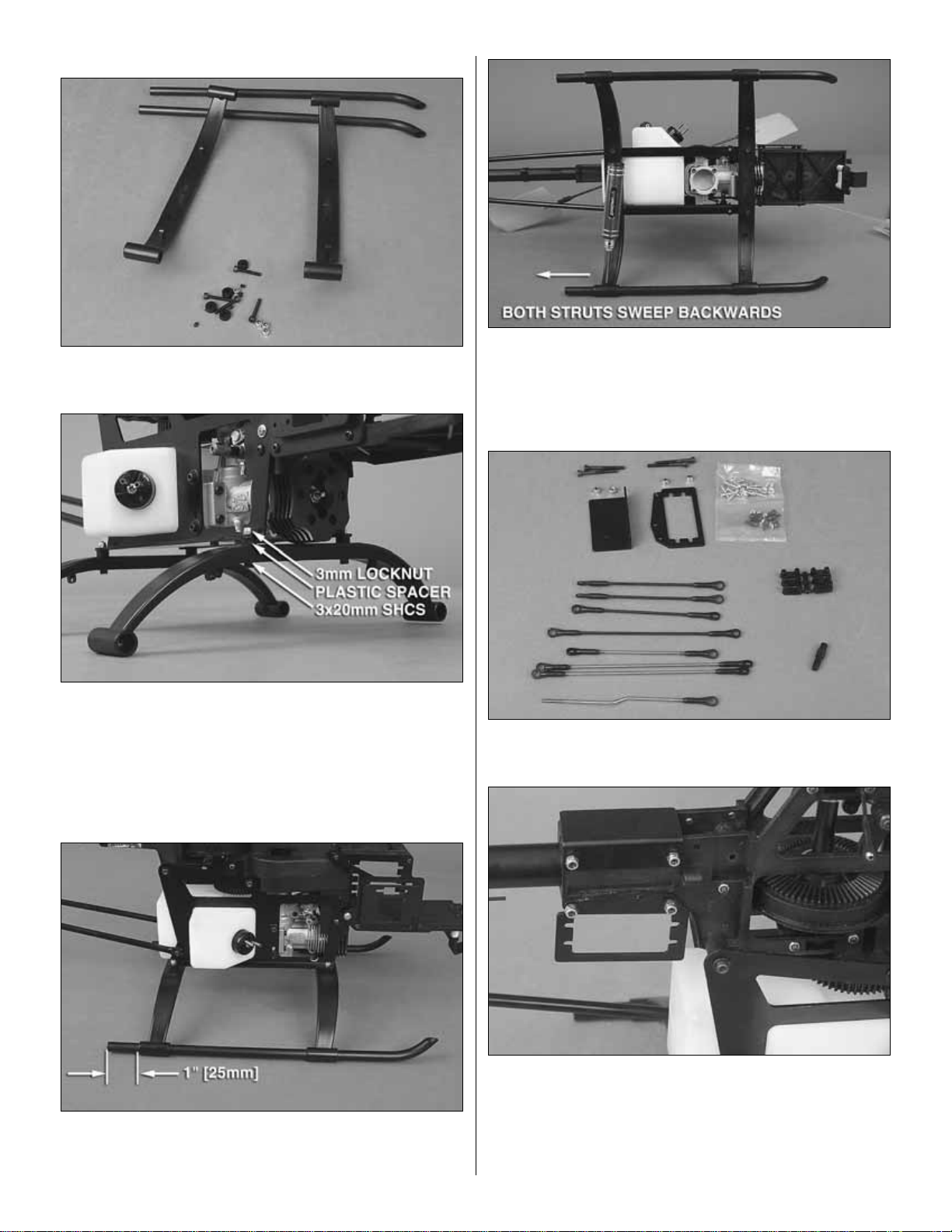
❏ 2. Slide the landing gear skids through the struts from
the front. Leave approximately 1" [25mm] protruding from
the back.
❏ 3. Install the four 3x4mm set screws into the inside of the
struts.These are used to lock the struts to the skids. Please
be careful not to overtighten.
GYRO MOUNT AND TAIL ROTOR SERVO MOUNT
Bag 4 Contents: Tail Rotor Servo Mount, Linkage Rods,
Tail Rotor Pushrod Coupler, Servo Retainers
❏ 1. Install the gyro and servo mount using four 3x30mm
SHCS and four 3mm nylon lock nuts as shown above.Push
the boom all the way f orward into the frame while turning the
rotor head before tightening the bolts down completely.
Please make sure the boom is far enough forward to
engage the tail drive.
14
Page 15

15
❏ 2. Thread the plastic tail rotor pushrod coupler onto the
short pushrod at least 1/4" [6.4mm]. If you find the coupler
difficult to thread on you can use a hobby knife to chamfer
the ball link.
❏ 3.Thread the coupler and pushrod onto the tail pushrod
as shown.
HORIZONTAL FIN ALIGNMENT
❏ Align the horizontal fin and tighten the bolts that were left
loose earlier.
SERVOS AND POWER SWITCH
Please follow the manuf acturer’s instructions for y our servos.
Install the grommets and eyelets and remove the servo arm
screws and servo arms.
❏ 1. Use the picture above as a reference when installing
the throttle and collective servos.
❏ 2. Remove the left side servo frame by removing the five
screws as shown above.
❏ 3.Now is the best time to install the receiv er pow er s witch.
EQUIPMENT INSTALLATION
Page 16

❏ 4. The collective and throttle servos are mounted on the
inside of the frame.Slide the throttle servo into the frame as
shown above. Install a 2.6x10mm screw and use a plastic
servo nut behind the servo.Tighten the 2.6mm screw until the
grommet begins to compress. Install the other three screws
and the plastic servo nut on the opposite end of the servo.
❏ 5.Install the collective servo using f our 2.6x10mm scre ws
and two plastic servo nuts. Re-install the ser vo frame with
the five screws you removed earlier.
❏ 6.Install the forw ard/aft cyclic servo using four 2.6x10mm
screws.Note servo arm direction.
❏ 7. Install the left/right cyclic servo using four 2.6x10mm
screws.Note s e rvo ar m d i r e ct i o n .
❏ 8.Install the tail rotor servo as sho wn using four 2.6x10mm
screws and two plastic servo nuts.
BATTERY, RECEIVER AND GYRO
❏ 1.Wrap the batter y with 1/4" foam. Use electrical tape to
attach the foam to the battery. Place the battery on the front
tray and attach it with electrical tape.
❏ 2.Place a piece of 1/4" foam on top of the battery and place
the receiver on top of the foam.Wrap lightly but securely with
electrical tape, leaving room for the foam to absorb vibration.
16
Page 17

17
RECEIVER ANTENNA
❏ 1. Slide the antenna tube into the mounts on the bottom of
the landing gear. Cut two pieces of fuel tubing 1/4" [6.4mm]
long and slide onto the tube in the front and back to capture
it. Slide the receiver antenna through the tube. Use a rubber
band to attach the antenna to the horizontal fin.
❏ 2. Following the manufacturer’s instructions, install your
gyro as shown. Use zip ties or Velcro®to bundle the excess
wire and prevent it from reaching the gears.
CONNECTING THE SERV OS TO THE RECEIVER
❏ Using the table above , plug the servos into the appropriate
channels on the receiver.
RECEIVER CHANNEL ASSIGNMENTS
LEFT / RIGHT FOR/AFT
RECEIVER TYPE CYCLIC CYCLIC TAIL ROTOR GYRO GAIN COLLECTIVE THROTTLE
Futaba PPM / FM CH 1 CH 2 CH 4 CH 5 CH 6 CH 3
Futaba PCM 1024 CH 1 CH 2 CH 4 CH 5 CH 6 CH 3
Futaba PCM 2048 G3 CH 4 CH 5 CH 2 CH 3 CH 6 CH 1
Hitec CH 1 CH 2 CH 4 CH 5 CH 6 CH 3
JR CH 2 CH 3 CH 4 CH 5 CH 6 CH 1
Airtronics CH 2 CH 1 CH 4 CH 5 CH 6 CH 3
Multiplex CH 1 CH 2 CH 3 CH 6 CH 4 CH 5
Page 18

FUTABA: 6EXH – 7CH – 9CH
This manual assumes you have already read through your
transmitter operating instructions and are familiar with its
operation. The settings shown will be for a beginner;
recommendations for intermediate and 3D pilots are on
page 23. The settings provided can be used as a star ting
point for other transmitters but please verify the model is set
up correctly before flying. Settings such as the servo
reversing can vary depending on the radio manufacturer
and which servo you use.The settings shown are for Futaba
transmitters and Futaba servos.
Before setting up the servo arms and linkages, make
sure the servos are hooked up properly and rotate in the
proper direction.
TRANSMITTER PREPARATION
❏ Using the instructions provided with your r adio, select a ne w
model memory on your transmitter. Perform a reset on the
model memory to ensure that previous settings are eliminated.
WARNING: Please make absolutely sure you have
selected an empty model memory before starting.
RESET MODEL MEMORY
6EXH
7CH
9CH
❏ 1.Futaba T6EXH:Press (Select) until you see the [SWSH]
option. Verify that it is set to 1-S for swashplate type. Next
select the [MODL] menu and press the (Select) button. The
transmitter will show [REST CLR]. Now hold the (+) slider
upwards at least two seconds to execute the reset.
RADIO SETUP
18
L/R CYCLIC F/A CYCLIC THROTTLE TAIL ROTOR GYRO COLLECTIVE
EPA/ATV 110% / 110% 110% / 110% 100% / 90% 100% / 100% 100% / 100% 100% / 100%
D/R 100% 100% 100%
EXP -30% -30% -30%
Reverse (Futaba) 1 – Normal 2 – Normal 3 – Reverse 4 – Reverse 5 – Normal 6 – Normal
Servo Arm Length 10.5mm 10.5mm 13mm 17.5mm 10.5mm
Sub Trim 0 0 0 0 0 0
Trim Step* 4* -- 1 4* -- 1 4 4* -- 1
MODEL TYPE H-1
TH-CUT ACT Rate: -10% Thr: 5% SW-H
Fail Safe Low Throttle–Idle
GYRO (Head Hold) SW-E MODE - GY UP> 60% CT>60% DN>55%
HOV-THR INH - Best to use mechanical adjustments
HOV-PIT INH - Best to use mechanical adjustments
Throttle Hold ACT POS>+- 0% R-OF> INH RT>+- 0%
THROTTLE CURVE
Normal 0% 25% 50% 75% 100%
PITCH CURVE
Normal 45% / -2° 55% 65% / +4.5° 82% 100% / +10°
Hold 30% / -4° 47% 65% / +4.5° 82% 100% / +10°
SETUP QUICK REFERENCE
*After initial flights, reduce trim step to 1 for a finer adjustment.
Page 19

19
❏ 2. Futaba T7CH: Select the [PARAMETER] menu and
verify the model [TYPE>] is set to [H-1]. Position the cursor
on [RESET>EXECUTE]. Press the rotary dial and hold it for
two seconds. The screen will show [SURE?]. Press the
rotary dial again to confirm and execute the reset.
❏ 3. Futaba T9CH: Select the [PARAMETER] menu and
verify the model [TYPE>] is set to SWH1.Position the cursor
on [RESET>EXECUTE]. Press the rotary dial and hold it for
two seconds. The screen will show [SURE?]. Press the
rotary dial again to confirm and execute the reset.
SET MODULATION TYPE
6EXH
7CH
9CH
Most computer radios are capable of transmitting in FM/PPM
or PCM. Depending on your radio and receiver, you must set
the modulation type in the radio. If the modulation type is
wrong, the receiver and servos will not operate at all. If you
are having problems, this is the first thing to check.
Once the modulation type is changed, it is necessary to
power down and power up again before the change will take
effect. Futaba radios also keep the modulation type in
memory for each model. If the modulation changes from
model to model, then the transmitter must be powered down
and up again before the controls will work.
❏ Futaba T6EXH:Select the [MODL] menu and press (Select)
button twice.The screen should now show [PULS] [PPM/PCM].
Use the data and button to select the type.
❏ Futaba T7CH:Select the [PARAMETER] men u and use the
and cursor buttons to scroll down to the [MODUL>]
line. Use the rotary dial to select either [PCM] or [PPM].
❏ Futaba T9CH: Select the [PARAMETER] menu and use
the and buttons to scroll down to the [MODUL] line.
Use the rotary dial to select either [PCM] or [PPM].
MODEL NAME
6EXH
7CH
9CH
❏ Futaba T6EXH: Select the [MODL] menu and press the
(Select) button three times.Use the and data buttons
to change letters and use the (Select) button to move to the
next character.
❏ Futaba T7CH: Select the [MODEL] menu and use the
button to move down to [NAME]. Use the Rotary Dial to
change letters and the and buttons to change
positions within the name.
❏ Futaba T9CH: Select the [MODEL] menu and use the
and buttons to mov e down to [NAME].Use the Rotary
Dial to change letters and the and buttons to change
positions within the name.
EXPONENTIAL
Exponential should be used to soften the control feel around
center. Futaba radios use a “–” percentage to soften the
sensitivity.Please read your transmitter’s instruction manual
to determine if “–” or “+”e xponential should be used.Futaba
users should start out with –30% exponential on the
following controls: Forward and Aft cyclic, Left and Right
cyclic, and Tail Rotor.
Most radios allow you to set the e xponential f or low and high
rates independently; you should set both rates to the same
value in case you accidentally have the dual rate switched
on. Dual rates are not needed on the Kinetic .50. If you still
feel the model is too sensitive, increase the exponential %
until you are satisfied with the overall feel.
Page 20

6EXH
7CH
9CH
❏ Futaba T6EXH:Press the (MODE) button until the screen
shows [D/R ch1 100%]. Press the (Select) button until the
screen shows [EXPO CH1 + – 0%]. Use the button and
decrease to –30%. Flip the Dual Rate switch on the
transmitter and adjust the low/high rate also. Repeat this for
the forward/aft (CH2) and tail rotor (CH4).
❏ Futaba T7CH:Select the [D/R,EXP] menu.Press the cursor
button to move do wn to [EXP + – 0%]. Use the rotary dial
to set the value to –30%. Cursor back up to [CH> 1-AIL] and
turn the rotary dial clockwise one position. You will notice the
arrow next to AIL changes.This is the low rate setting for CH1
AIL; set it to –30%.Turn the rotary dial clockwise one position
and the display will change to [CH> 2-ELE]. Continue setting
the high and low rate exponential to –30% for forward/aft cyclic
(CH2) and tail rotor (CH3).
❏ Futaba T9CH:Select the [*D/R,EXP] menu.Press the cursor
button to move down to [EXP + – 0%]. Use the rotary dial
to set the % to -30%.Cursor back up to [CH> 1-AIL] and turn
the rotary dial clockwise one position.You will notice the arrow
next to AIL changes.This is the low rate setting f or CH1 AIL;set
it to –30%.Turn the rotary dial clockwise one position and the
display will change to [CH> 2-ELE]. Continue setting the high
and low rate exponential to –30% for (CH4) tail rotor.
SERVO REVERSING
6EXH
7CH
9CH
WARNING:These settings are ONLY for Futaba radios using
Futaba servos.Please double-check the settings before flight
to be absolutely sure they are correct.
❏ Futaba T6EXH with Futaba Servos: Select the [REVR]
menu. Reverse channels 3-Throttle and 4-Tail Rotor.
Channels 1, 2, 5, and 6 should remain as [NORM]
❏ Futaba T7CH with Futaba Servos:Select the [REVERSE]
menu. Reverse channels 3-Throttle and 4-Tail Rotor.
Channels 1, 2, 5, and 6 should remain as [NORM]
❏ Futaba T9CH with Futaba Servos:Select the [REVERSE]
menu. Reverse channels 3-Throttle and 4-Tail Rotor.
Channels 1, 2, 5, and 6 should remain as [NORM]
20
Page 21

21
END POINT ADJUSTMENTS
6EXH
7CH
9CH
❏ Futaba T6EXH: Select the [EPA] menu and set CH1 and
CH2 to 110% (left/right and forward/aft).
❏ Futaba T7CH: Select the [EPA] menu and set CH1 and
CH2 to 110% (left/right and forward/aft).
❏ Futaba T9CH: Select the [EPA] menu and set CH1 and
CH2 to 110% (left/right and forward/aft).
SUB-TRIM
If possible, sub-trim should be avoided.Most servo arms are
designed with an odd number of splines which allows you to
rotate it 90° or 180° and change the center position of the
arm. If you cannot get the arm perfectly straight, then a
small % of sub-trim may be used but it is best to a v oid using
it. Sub-trim can decrease the available throw one direction.
FAIL-SAFE
6EXH
7CH
9CH
This function is only available for PCM receivers and cannot
be used on FM.What fail-safe provides is a set of commands
for the servos to follow if the receiver should experience
interference for more than two seconds. Please set the
throttle [FAIL SAFE] to bring the engine back to idle and
leave all other servos set to [HOLD].This will help to prevent
damage in the case of severe interference.
GYRO FUNCTION
6EXH
7CH
9CH
The gyro function is only used on gyros that have a remote
gain that plugs into the receiver. If your gyro does not have
remote gain, please follow the instructions provided with the
gyro and set it up for heading hold mode.
❏ Futaba T6EXH: Select the [GYRO] menu. Enable the
function and set the gain to +60%.
Page 22

❏ Futaba T7CH: Select the [GYRO] menu. Enable the
function and set the switch to [SW -E] (Flight Condition Switch).
Set all positions to [A 60%] which is A VCS (Heading Hold) and
60% gain.
❏ Futaba T9CH: Select the [GYRO] menu. Enable the
function and set the switch to [SW -E] (Flight Condition Switch).
Set all positions to [A 60%] which is A VCS (Heading Hold) and
60% gain.
THROTTLE CUT
7CH
9CH
❏ Futaba T7CH: Select the [TH-CUT] menu. Enable the
function and set the switch to [SW-H], using the following
settings: [RATE –10%] — [THR> 5%]
❏ Futaba T9CH: Select the [TH-CUT] menu. Enable the
function and set the switch to [SW-H], using the following
settings: [RATE–10%] — [THR>5%] — [POSI->DOWN]
HOVER AND THROTTLE TRIMS
Since the hover and throttle trims operate only in normal
flight mode, it’s best to disab le them and mak e changes with
mechanical adjustments.
HI-LO PITCH TRIMS
Set the “CONTROL” to null on both HI and LO pitch trims.
THROTTLE CURVE
6EXH
7CH
9CH
❏ Futaba T6EXH:Select the [N-TH] menu. Set Point #1 to 0%.
Press (Select) to move to the next point. Set Point #2 to 25%,
set Point #3 to 50%, Point #4 to 75% and Point #5 to 100%.
❏ Futaba T7CH: Select the [TH-CRV(N)] menu. Press the
button until you are editing Point #1. Use the rotary dial
to set it to 0%.Press the button to move to Point #2 and
set it to 25%. Set Point #3 to 50%, Point #4 to 75% and
Point #5 to 100%.
❏ Futaba T9CH: Select the [TH-CV/NOR] menu. Set Point
#1 to 0%. Press the button to move to Point #2 and set
it to 25%.Set P oint #3 to 50%, Point #4 to 75% and Point #5
to 100%.
22
Page 23

23
PITCH CURVE
6EXH
7CH
9CH
❏ Futaba T6EXH: Select the [N-PI] menu. Set Point #1 to
45%. Press (Select) to move to Point #2 and set it to 55%.
Continue to set Point #3 to 65%, Point #4 to 82% and Point
#5 to 100%.
❏ Futaba T7CH: Select the [PI-CRV(N)] menu. Press the
button until you are editing Point #1. Use the rotary dial
to set it to 45%. Press the button to move to Point #2.
Set it to 55%. Set Point #3 to 65%, Point #4 to 82% and
Point #5 to 100%.
❏ Futaba T9CH: Select the [PI-CV/NOR] menu. Set Point
#1 to 45%. Press the button to move to Point #2. Set it
to 55%. Set Point #3 to 65%, Point #4 to 82% and Point #5
to 100%.
INTERMEDIATE AND BASIC AEROBATIC CURVES
Please take the time to become accustomed to the new setup .
The increased negative collective will make the controls very
sensitive.Be aware of switches, as well.Accidentally switching
to “Idle Up 2”, for instance , automatically advances the engine
to full throttle.
ADVANCED 3D AND AEROBATIC CURVES
Once accustomed to the curves above, you can use these
curves for everything from everyday flight to advanced 3D
aerobatics.The throttle mixes help maintain rotor head speed.
If your Kinetic .50 loses head speed during maneuvers,
increase the throttle mix percentages.
THROTTLE CURVE POINT 1 POINT 2 POINT 3 POINT 4 POINT 5
Normal 0% 25% 50% 75% 100%
Idle Up 1 25% 37% 50% 75% 100%
Idle Up 2 85% 70% 60% 80% 100%
PITCH CURVE POINT 1 POINT 2 POINT 3 POINT 4 POINT 5
Normal 45% / -3° 55% 65% / +4.5° 82% 100% / +10°
Idle Up 1 35% / -4.5° 50% 65% / +4.5° 82% 100% / +10°
Idle Up 2 0% /-10° 32% 65% / +4.5° 82% 100% / +10°
Hold 30% / -5° 47% 65% / +4.5° 82% 100% / +10°
BASIC AND INTERMEDIATE AEROBATIC CURVES
THROTTLE CURVE POINT 1 POINT 2 POINT 3 POINT 4 POINT 5
Normal 0% 25% 50% 75% 100%
Idle Up 1 25% 37% 50% 75% 100%
Idle Up 2 100% 70% 50% 70% 100%
PITCH CURVE POINT 1 POINT 2 POINT 3 POINT 4 POINT 5
Normal 35% / -4.5° 42% 50% / 0° 82% 100% / +10°
Idle Up 1 35% / -4.5° 42% 50% / 0° 82% 100% / +10°
Idle Up 2 0% /-10° 25% 50% / 0° 82% 100% / +10°
Hold 20% / -7° 47% 50% / 0° 82% 100% / +10°
THROTTLE MIXES
L/R Cyclic Throttle 40% F/A Cyclic Throttle 40% T/R Throttle 40%
ADVANCED 3D AND AEROBATIC CURVES
Page 24

SERVO SETUP AND LINKAGES
Most servo arms have an odd number of splines, which
allows you to rotate it 90°, 180° or 270° to help with the
centering. All servo arms should be perpendicular to the
servos when installed in the Kinetic .50.
FORWARD/AFT CYCLIC SETUP
❏ 1. Turn on the transmitter and receiver and center the
sticks.Test fit a servo arm onto the ser vo.The arm must be
perpendicular to the servo, as shown above. (If the ar m isn’t
perfectly aligned, rotate it 90° and recheck alignment.Repeat
until 90° alignment is achieved.)
❏ 2. Remove the arm and using a pair of wire cutters, clip
off the three unused sides. Install a metal control ball into
the servo arm at 10.5mm from center (second hole out from
center on Futaba arms). Using thread locker, install the
2mm nut onto the back side of the servo arm and tighten.
❏ 3. Verify the servo arm clears the left/right cyclic servo.If
needed, trim the arm as required.
❏ 4. Install the servo arm and screw as shown above.
Locate the forward/aft cyclic linkage and verify that it is
128mm long. Install linkage as shown above.
LEFT/RIGHT CYCLIC SETUP
❏ 1. Turn on the transmitter and receiver and center the
sticks.Test fit a servo arm onto the servo.The arm must be
perpendicular to the servo, as shown.
❏ 2. Remove the arm and using a pair of wire cutters, clip
off the two unused sides. Install a metal control ball onto
both sides at 10.5mm from center (second hole out from
center on Futaba arms). Using thread locker, install the
2mm nuts onto the back side of the servo arm and tighten.
10.5mm
10.5mm
24
128mm
(Sketch not to scale)
Page 25

25
❏ 3. Install the servo arm and screw as shown above.Locate
the left/right cyclic linkages and make sure they are both
148mm long. Install the linkages and the servo arm screw.
❏ 4. Please remove the bellcrank to swashplate linkage as
shown above and verify it is 51mm long. Repeat on the
opposite side.
COLLECTIVE SERVO SETUP
❏ 1. Make sure that the transmitter and receiver are “ON”
and the sticks are centered. Put a servo arm in place,
making sure that one side is perpendicular to the servo.
❏ 2. Remove the arm and using a pair of wire cutters, clip
off the three unused sides. Install a metal control ball into
the servo arm at 10.5mm from center (second hole from
center on Futaba arms). Using thread locker, install the
2mm nut onto the back side of the ball and tighten.
❏ 3. Verify the collective pushrod is 90mm long. Install as
shown above.
❏ 4.Install the collective servo arm screw.
10.5mm
148mm
(Sketch not to scale)
90mm
(Sketch not to scale)
51mm
(Sketch not to scale)
Page 26

THROTTLE SETUP
❏ 1. Make sure that the transmitter and receiver are “ON”
and the sticks are centered.Put a servo arm in place, making
sure that one side is perpendicular to the servo.
❏ 2. Remove the arm and using a pair of wire cutters, clip
off the three unused sides. Install a metal control ball into
the servo arm at 13mm from center (third hole out from
center on Futaba arms). Using thread locker, install the
2mm nut onto the back side of the ball and tighten.
❏ 3.Ver ify the throttle pushrod is 90mm long. Install the ball
link onto the throttle arm. Make sure that the throttle arm on
the engine is straight up and down when the stick is at half
throttle.The O.S..50 SX-H Hyper has indentations on the carb.
❏ 4. Leave the other side of the linkage loose. Move the
throttle to idle and verify the throw is correct and does not bind.
Move the throttle to full and place the linkage over the control
ball. Verify that the servo is traveling the proper distance. If
necessary use the radio’s End Point Adjustments.
❏ 5.Install the servo arm screw.
TAIL ROTOR SERVO
❏ 1.With the transmitter and receiver turned on, make sure
the gyro is centered. (Use Normal mode instead of Heading
hold.) Place a servo arm onto the servo and verify the arm
is perpendicular to the servo.
❏ 2. Remove the arm and using a pair of wire cutters, clip
off the three unused sides. Install a metal control ball into
the servo arm at 17.5mm from center (fourth hole out from
center on Futaba arms). Using thread locker, install the
2mm nut onto the back side of the ball and tighten.
❏ 3. Install the ser vo arm screw. Move the T/R stick to full
left.Hold the pushrod ball link ov er the control ball and v erify
the servo throw is correct. Balance the left and right throws
by adjusting the pushrod length. Make sure the pushrod
does not bind when moving either direction.Try to keep the
gyro limit near 100% by adjusting the length of the servo
arm. Your goal is to have maximum mechanical throw
without binding and have the gyro limit at 100%.
13mm
26
90mm
(Sketch not to scale)
Page 27

27
GY401 GYRO SETUP
If you are using a digital servo such as the Futaba S9254 or
S9253, the DS mode switch should be “ON”.Otherwise, set
it to “OFF”.The “DIR” should be set to “NOR” or “OFF”.
INSTALL MAIN ROTOR HEAD LINKAGES
❏ 1.Find the two pre-assembled collective linkages and v e rify
they are 102mm long.Install the linkages as shown above.
❏ 2.The short double links should have a 1mm gap betw een
the ball links as shown above.
MAIN BLADES
Warning: The blade root reinforcements must be glued to
the main blades. Please inspect the blades for damage
before assembling them.Do not exceed 1700 RPM with the
wood blades or failure may occur. Blades are considered
consumable items and should be discarded if there is any
sign of damage.
❏ 1. Position the blade as shown above and test fit the top
reinforcement on the blade.
❏ 2.T urn ov er the blade and test fit the bottom reinf orcement.
HEAD AND LINKAGES
102mm
(Sketch not to scale)
Page 28

❏ 3. Once you have verified everything fits properly, mix up
some 30-minute epoxy and apply it to the exposed wood on
the root of the blade.Install the top and bottom reinforcements
as shown above. Double check your work to verify the
reinforcements are installed properly. Install and tighten the
two 2.6mm screws into the reinforcements as shown.
❏ 4. Use a paper towel dampened with isopropyl alcohol to
remove the e xcess glue from the blade.Before the epoxy sets,
install the blades into the grips to clamp the reinforcements
down onto the blade.Once the epoxy has set, you can proceed
to the next step.
❏ 5. Using the 4mm bolts and nylon lock nuts, install the
blades into the grips as shown.
BLADE BALANCING
Note: All main blades must be balanced before use. We
recommend using the Heli-Max Blade Balancer (HMXE4855).
❏ 1. Apply the two colored stripe decals to the tips of your
main rotor blades (for use in blade tracking later on).
❏ 2. Prepare the balancer for use by rotating the brass
adjustment dial until the bubble in the vial indicates level. Make
sure that the blade balancer does not move during this process.
❏ 3. Place one blade onto the balancer with the leading
edge against the side with the level. Shift the blade on the
balancer until the bubble indicates level. The middle of the
black balancing tray is now at the C.G. of this blade. Mark
this position on the blade with a felt tip pen.
❏ 4.Line up the ends of both blades.Transfer the mark you
made on the first blade to the second blade.
28
Page 29

❏ 5.Position the second blade on the tray, with the mark at
the center.Add balancing or electrical tape to the lighter end
until the bubble indicates that both sides are level.The C.G.
of both blades is now matched. If the tape ends overlap,
make sure the overlapping end points to the
trailing
edge of
the blade.
❏ 6. Your Heli-Max Blade Balancer includes four sizes of
blade mounting plates and a nylon mounting bolt.Select the
mounting plate that best fits the holes in the blade grips.
Secure the mounting plate and two blades to the balancer
with the nylon mounting bolt.
❏ 7.Add tape to the C.G.of the lighter blade until the bubble
level indicates that the two blades balance.Using a different
tape color in this step will remind you that future
adjustments will require both balancing steps.
PITCH CURVES
❏ 1.The pitch gauge is used by setting the desired pitch on the
gauge and adjusting the blade pitch until the top (or bottom) of
the gauge is parallel with the flybar.Make sure the flybar is level
while doing this.If y ou need to make an adjustment to the pitch
of the blades, then adjust the long linkages that connect the
swashplate to the mix er arm.The goal is to have positive 10° at
full throttle/collective and negative 10° at low throttle/collective.
Then use the pitch curves within the radio to adjust the
collective pitch range.
29
PITCH CURVE POINT 1 POINT 2 POINT 3 POINT 4 POINT 5
Normal 45% / -2° 55% 65% / +4.5° 82% 100% / +10°
Hold 30% / -4° 47% 65% / +4.5° 82% 100% / +10°
PITCH CURVE SETUP
Warning: Beginners should use a maximum negative 2° collective with the throttle stick at idle. It helps to reduce the
sensitivity of the collective and prevents hard landings when the throttle is brought back to idle.Later, once you advance and
need more negative collective, simply make adjustments in the transmitter
.
Page 30

❏ 2. Tur n on the transmitter and receiver.Move the collective
stick to full throttle. Place the pitch gauge on the blade as
shown and set it to +10°.Align the top (or bottom) of the pitch
gauge with the flybar. If necessary, adjust the long linkage
between the mixer and the s w ashplate .Once the correct pitch
has been established, adjust the length of the linkage on the
opposite side to match.
❏ 3. On your transmitter, place the throttle/collective stick in
the center.Verify that the setting is around +4.5°.If the pitch is
off, adjust P oint #3 in the pitch curve on your radio .If you adjust
Point #3, adjust Points #2 and #4 to maintain a smooth curve.
❏ 4. Lower the throttle/collective stick on the transmitter to
the bottom. Verify that the setting is around –2°. Use pitch
curve Point #1 if adjustments are needed. Once you are
finished, set Point #2 to keep an even curve.
❏ 5. Repeat the pitch curve setup for the Hold function and
any other Idle Ups you may need.
FUEL LINES
❏ Cut a piece of 4" [102mm] fuel line for the carburetor
pickup line and install. Use the remaining fuel line for the
pressure line to the muffler.
MUFFLER INSTALLATION
❏ Install your muffler f ollowing the man ufacturer’ s instructions.
Mounting hardware should be included with the muffler.
BODY AND MOUNTS
❏ 1. Slide the threaded rod through the frame.Using thead
locking compound, install the body mounts as shown abov e.
FINAL ASSEMBLY
30
Page 31

31
❏ 2.T rim the front of the body as shown abo ve .Make a clean
cut by making several passes with a hobby knife. Mark the
body 5/8" [16mm] up from the back edge and 5/8" [16mm]
right. Drill 1/4" [6.4mm] holes for the rubber grommets.Install
the grommets into the body.
❏ 3. Install the front body clamp using two 3x8mm self-
tapping screws. Please note that the wider end should face
the back of the canopy.
❏ 4. Depending on your muffler, it may be necessary to cut
the body for clearance.Leave at least 1/4" [6.4mm] between
the body and muffler.Mount the body by sliding the canopy
latch onto the “L” bracket on the servo tray. Lift up the back
portion of the body and push the grommets onto the rear
body mounts.
❏ 5. Once the body is installed, trim and test fit the
windshield. When satisfied with the fit, drill 1/16" [1.5mm]
holes at the locations shown and use 2x3mm self-tapping
screw to attach the windshield. Repeat for the other side of
the body.
DECALS
❏ Clean the body thoroughly with glass cleaner to remove
any mold release left over from manuf acturing.Spraying glass
cleaner on the body before applying the decals enables you
to reposition them until they are perfectly placed. Once in
place, use a squeegee to remove the cleaner, allowing the
decals to “stick”in place.
Page 32

CHECK THE CONTROL DIRECTIONS
Turn on the transmitter and allow the gyro 5 seconds to
initialize before moving the helicopter or oper ating the sticks .If
everything has been adjusted properly the swashplate should
be level with the main frame when the sticks are centered.
Forward Cyclic
❏ Look at the helicopter from the right side. Push the right
stick forward.The swashplate should tilt forward as shown.
Aft Cyclic
❏ Pulling the right stick back should make the swashplate
tilt backwards.
Left Cyclic
❏ View the helicopter from the rear. Pushing the right stick
to the left should make the swashplate tilt to the left.
Right Cyclic
❏ Continue to view the helicopter from the rear. Pushing
the right stick to the right should make the swashplate tilt to
the right.
Ascend Collective
PREPARE FOR FLIGHT
32
Page 33

33
❏ When the left (collective) stick is pushed forward, the
swashplate should move up and the carburetor should open.
Descend Collective
❏ When the left (collective) stick is pulled backward, the
swashplate should mov e down and the carb uretor should close.
Left T ail Rotor
❏ When the left (tail rotor) stick is moved to the left, the tail
pitch slider should move to the right as shown.
Right T ail Rotor
❏ When the left (tail rotor) stick is mov ed to the right, the tail
pitch slider should move to the left as shown.
Gyro Compensation Direction
❏ Pick the helicopter up by the main shaft and rotate the nose
to the left (counterclockwise).The gyro should compensate by
moving the tail rotor pitch slider to the left (toward the tail
boom). If the pitch slider moves right instead, change the
reversing switch for the servo.
Page 34

RANGE CHECK
Ground check the range of your radio before the first flight of
the day. With the transmitter antenna collapsed and the
receiver and transmitter “ON”, you should be able to walk at
least 100 feet awa y from the model and still ha ve control.Have
an assistant stand by your model and tell you what the servos
are doing while you work the controls. If the controls do not
respond correctly , do not fly! Find and correct the prob lem first.
Look for loose servo connections or broken wires, corroded
wires on old servo connectors, poor solder joints in your
battery pack or a defective cell, or a damaged receiv er crystal
from a previous crash. Failure to follow these safety
precautions may result in severe injury to you and others.
Keep yourself and all spectators away from the plane of
rotation of the rotors. Keep these items away from the rotors:
loose clothing (shirt sleeves, ties, scarfs), long hair, or loose
objects (such as pencils or screwdrivers) that may fall out of
shirt or jacket pockets into the rotors.The spinning blades of a
model helicopter can cause serious injury.When choosing a
flying site for your model, stay clear of buildings, trees and
power lines.AVOID flying in or near crowded areas.DO NOT
fly close to people, children or pets. Maintain a safe pilot-tohelicopter distance while flying.
BALANCE THE MODEL (C.G.)
The Kinetic .50 should balance level when picked up by the
flybar with the flybar perpendicular to the tail boom. If the tail
drops, the helicopter is tail heavy and you need to add
weight to the front or if possible move equipment forward. If
the nose drops, you need to add some weight to the tail of
the helicopter or move equipment back as needed.
The C.G. on a model helicopter is not as critical as it is on
model airplanes, but can cause some trim problems as you
learn to fly .If nose weight is needed, consider using a larger
capacity battery.
At this stage, the model should be in ready-to-fly condition.
IDENTIFY Y OUR MODEL
Whether you fly at an AMA sanctioned R/C club site or
somewhere on your own, y ou should alwa ys hav e y our name,
address, telephone number and AMA number on or inside
your model.It is required at all AMA R/C club flying sites and
AMA sanctioned flying events .Fill out the identification tag on
page 38 and place it on or inside your model.
CHARGE THE BA TTERIES
Follow the battery charging instructions that came with your
radio control system. You should always charge your
transmitter and receiver batteries the night before y ou go flying,
and at other times recommended by the radio manufacturer.
Read and abide by the following e xcerpts from the Academy
of Model Aeronautics Safety Code.For the complete Safety
Code, refer to
Model Aviation
magazine, the AMA web site
or the Code that came with your AMA license.
GENERAL
1) I will not fly my model aircraft in sanctioned events, air
shows, or model flying demonstrations until it has been
proven to be airworthy by having been previously,
successfully flight tested.
2) I will not fly my model aircraft higher than approximately
400 feet within 3 miles of an airport without notifying the
airpor t operator. I will give right-of-way and avoid flying in
the proximity of full-scale aircraft. Where necessar y, an
observer shall be utilized to supervise flying to avoid
having models fly in the proximity of full-scale aircraft.
3) Where established, I will abide by the safety rules for the
flying site I use, and I will not willfully and deliberately fly my
models in a careless, reckless and/or dangerous manner.
5) I will not fly my model unless it is identified with my name
and address or AMA number, on or in the model. Note:
This does not apply to models while being flown indoors.
7) I will not operate models with pyrotechnics (any device
that explodes, burns, or propels a projectile of any kind).
RADIO CONTROL
1) I will have completed a successful radio equipment ground
check before the first flight of a new or repaired model.
2) I will not fly my model aircraft in the presence of spectators
until I become a qualified flier, unless assisted by an
experienced helper.
3) At all flying sites a straight or curved line(s) must be
established in front of which all flying takes place with the
other side for spectators. Only personnel involved with
flying the aircraft are allowed at or in the front of the flight
line. Intentional flying behind the flight line is prohibited.
4) I will operate my model using only radio control
frequencies currently allowed by the Federal
Communications Commission.
5) I will not knowingly operate my model within three miles
of any pre-existing flying site except in accordance with
the frequency sharing agreement listed [in the complete
AMA Safety Code].
9) Under no circumstances may a pilot or other person
touch a powered model in flight; nor should any part of
the model other than the landing gear, intentionally touch
the ground, except while landing.
AMA SAFETY CODE (EXCERPTS
)
PREFLIGHT
34
Page 35

35
Please try to find a local club (check www.modelaircraft.orgfor
listings) or find an experienced modeler for help before starting
to fly. There are a lot of mistakes that can be made during the
assembly of helicopters that an experienced modeler can catch.
They will help you get the model setup properly and verify that
the model is trimmed out and ready for your first flight.
The web sites listed below are discussion forums for R/C
Helicopters and Planes.There is a lot of information available
on the forums.
www.rcgroups.com
www.rcuniverse.com
www.runryder.com
Computer flight simulators are excellent practice bef ore risking
your model.Great Planes RealFlight®G3.5 (GPMZ4405) is the
most realistic simulator available and is highly recommended.
CONTROLS
Shown below are the controls available on the Heli-Max
Kinetic .50 and how they operate during flight.
Forward Cyclic
Moving the right (cyclic) stick forward causes the helicopter
to lean forward and start moving forward.
Aft Cyclic
Moving the right (cyclic) stick backward causes the helicopter
to lean backward and start moving backward.
Left Cyclic
Moving the right (cyclic) stick to the left causes the helicopter
to lean left and start moving in that direction.
Right Cyclic
Moving the right (cyclic) stick to the right causes the helicopter
to lean right and start moving in that direction.
Ascend Collective
When the left (collective) stick is mov ed f orward, the helicopter
will ascend.
FLYING
Page 36

Descend Collective
When the left (collective) stick is moved downward, the
helicopter will descend.
Left T ail Rotor
When the left (tail rotor) stick is moved to the left, the
nose of the helicopter will move left and the helicopter will
rotate counterclockwise.
Right T ail Rotor
When the left (tail rotor) stick is moved to the right, the
nose of the helicopter will move right and the helicopter will
rotate clockwise.
TRAINING GEAR
If you have ne v er flown a helicopter bef ore, consider purchasing
training gear.It not only helps prevent crashes and tip-ov ers, b ut
prevents damage b y softening not-so-perfect landings.The HeliMax Training Gear (HMXE2025) is highly recommended.
FLYING CONDITIONS
During your first flight, it is very helpful to fly in light winds and
have a helper to keep an e y e on things around you.If you are
flying off grass, make sure it is cut low. This will allow the
helicopter to slide around without catching. Finally, make
sure there are no obstacles or distractions in your flying area.
BEFORE EACH FLIGHT
Please inspect the model for loose or damaged parts.
Inspect the main rotor blades and ball links. Make sure you
have selected the proper model in the transmitter and all of
the controls operate in the correct direction.
ST ARTING THE MODEL
Set the engine’s needle valve to the recommended factory
setting. Please review the manufacturer’s operating
instructions for the engine.
If you are flying at a club, be sure y ou use their frequency control
system.T urn on the radio first and select the correct model.Turn
on the helicopter next. Allow the gyro to initialize for at least 5
seconds before moving the model or using the transmitter.
Fill the fuel tank. Make sure the idle up switch on the
transmitter is set to normal mode and the throttle is at idle.
Check the throttle arm on the engine to verify it is at idle.
Attach the glow igniter to the glow plug. You must have a
solid hold on the blade grip in case the model starts at a
throttle position other than idle. Use the starter to turn the
engine over. If the engine does not want to start, check the
glow plug by removing it and attaching the glow igniter.
Verify that the needle settings are correct. It is possible the
engine could be flooded. If no problems can be found,
assume the engine is flooded.Remov e the fuel line from the
carburetor and try starting the engine again.
Once the model has been started and has warmed up,
remove the glow igniter. Carr y the model out to the location
where you plan on flying. Place the model on the ground and
walk back at least 30' [or 10m].
36
Page 37

37
ADJUST BLADE TRACKING
If you feel uncomfortable adjusting blade tracking by yourself,
please have a helper do the sighting f or you and simply fly the
model. Slowly bring the main rotor up to speed but do not lift
off the ground. Please wear safety glasses when performing
the next step. Observe whether the rotational planes of the
blades are the same. If they are not, adjust one of the short
double linkages to bring the blades into the same plane.
TAKEOFF
Slowly add power and observe the model. If you feel it
needs trimming at any time, simply lower the collective stick
all the way down to land and adjust the trim on the
transmitter.For now, simply bring the collective stick up until
the helicopter is “light on the skids”. As you become more
comfortable with the helicopter, you can lift higher off the
ground. Stay low until you become comfortable.
If you should get into trouble, simply bring the collective stick
down slowly and the helicopter will settle and land. This is
when the training gear serves its purpose, since it helps to
level the helicopter automatically before landing.The tr aining
gear will also allow the model to slide on most surfaces.
You will notice the cyclic controls lag behind your control
inputs.This is perfectly normal and something you get the feel
for with time.It’s normal to drift around in a hover until you are
used to flying the model.The cyclic controls on the Kinetic .50
are fairly sensitive so only small movements are necessary.
HOVERING
Once the helicopter is hovering, concentrate on holding the
helicopter in one spot. This can take some practice.Wind has
a big effect on the stability of the helicopter .Be patient and take
your time.Trying to rush the learning process can be costly.
LANDING
Level the helicopter into a ho ver and slowly decrease power
until the helicopter settles onto the ground.
BASIC MANEUVERS
Once you have become accustomed to ho vering, it is time to
work on moving the helicopter around.Just pic k some points
on the ground (you can mark the ground if you like) and fly
the helicopter over to them. Tr y to maintain a steady hover
directly over those points. For now, always keep the tail
pointing directly at you.This helps to keep your orientation.
Pirouettes: Add a small amount of tail rotor (left or right) and
try rotating the helicopter slightly sideways and see if you can
maintain the hover. If you get uncomfortable bring the tail
back towards you. Once you begin to feel comfortable, try
moving the helicopter to the side and turning back.Then fly
back to the other side in straight lines.
Once you become comfortable with those you can try
rotating the helicopter 360°, which is called a pirouette.The
helicopter can drift during pirouettes, so make sure you
have plenty of room to perform the maneuver.
After pirouettes, it is time to move onto nose-in ho vering. It is
best to wait for a calm da y.Take off and climb to 15'.Pr actice
half pirouettes, working from tail-in to nose-in hovering.Try to
lengthen the delay between the transitions. As you improve,
you’ll remain nose-in for longer periods of time.
Now it’s time to w ork into basic forward flight.Just take the basic
hovering maneuvers listed above and slowly go out farther and
faster, but always bring the helicopter back after one pass.
Practice controlled slow flight in close as well. The more time
you spend practicing, here the easier things will be later on.
AEROBATICS
When you become comfortable in fast forward flight, you can
slowly progress into aerobatics.Once you are in forward flight,
use the idle up switch to raise the rotor RPM for aerobatics;
this provides the power to fly inverted. Also, in wind, it may be
difficult to descend for a landing without the idle up on.
The first step is chandelles. Fly straight across in front of you
and pull up to a 45° angle.Now at the top, when the helicopter
slows down to a stop, apply some tail rotor to bring the nose
around 180° and continue back down on the 45° angle.
As you progress with the maneuver, you can pull to greater
angles, up to 90 degrees.This would be called a stall tur n.
Loops: Once you are comfortable with chandelles and stall
turns, it’s time to move onto the loop.The key to the loop is
entering with plenty of air speed. Start pulling aft cyclic to
enter the loop. As the model goes inverted at the top, pull
back on the throttle a little bit (towards negative (–)
collective) to help hold altitude. As the model comes back
vertical, add some positive (+) collective to speed. One of
the most common mistakes made on loops is using too
much negative (–) collective at the top of the loop.
Flips: These are a lot easier to perform than they sound.
Start with plenty of altitude. From an upright hover, slowly
add in full forward cyclic.As the model approaches vertical,
bring the collective stick back to center. As the model
Page 38

continues to fly inverted, you will need to start adding in
negative (–) collective (or pull the collective stick back
towards you) to maintain altitude. As the model transitions
back to vertical, again bring the collective stick back to the
middle and start adding in positive (+) collective as the
model comes back to the upright position.
It is all a matter of timing. The most important thing is to
move the sticks smoothly. If you are too aggressive with the
sticks, the head speed will drop and you will lose power.
Rolls: These are very similar to flips and require proper timing
on the collective.From fast forw ard flight, slowly mov e the stic k
to full right cyclic.As the model approaches knife edge (b lades
vertical), slowly move the collective stick towards 0°. As the
model approaches inverted, you should slowly move the
collective stick towards –5° (to maintain inverted flight). By the
time the model reaches knife edge again, the collective should
be near 0°. Slowly move the collective stick towards +5° to
maintain upright flight. This is a simple maneuver to perform
but one of the most difficult ones to perfect.
Inverted Hovering: Keep in mind flying a helicopter in v erted
is very difficult but can be learned. One of the problems is
three out of four controls are reversed (forward/aft cyclic,
collective and tail rotor).You have to mentally reverse these
while flying.It will take some pr actice.If you have a simulator ,
this is the best place to start.
Perform a half loop and hold the inverted por tion for short
periods of time.As you become accustomed to the re v ersed
controls, you will extend the time you fly inverted. This is
very difficult and will take some time to pick up. Also, make
sure you have plenty of altitude for recovery.
GOOD LUCK AND GREAT FLYING!
ORDERING REPLACEMENT OR MISSING PARTS
Replacement parts for the Heli-Max Kinetic .50 ARF are
available using the order n umbers in the Replacement P a rts
List located in the back of this manual. The fastest, most
economical service can be provided by your hobby dealer or
mail-order company.
To locate a hobby dealer, visit the Heli-Max web site at
www.helimax-rc.com.Choose “Where to Buy” at the bottom
of the menu on the right side of the page. Follow the
instructions provided on the page to locate a U.S., Canadian
or International dealer.
Parts may also be ordered directly from Hobby Services by
calling (217) 398-0007, or via facsimile at (217) 398-7721,
but full retail prices and shipping and handling charges will
apply. Illinois and Nevada residents will also be charged
sales tax. When ordering, please include a Visa®or
MasterCard®number and the expiration date of the card.
Mail parts orders and payments by personal check to:
Hobby Services
3002 N Apollo Drive, Suite 1
Champaign IL 61822
Be certain to specify the order number exactly as listed in
the Replacement Parts List. Payment by credit card or
personal check only; no C.O.D.
If additional assistance is required for any reason contact
Product Support at (217) 398-8970, Ext. 6, or by e-mail at:
helihotline@hobbico.com
PARTS LIST
38
Page 39

39
Stock # Description Contents
HMXE1008 ....Main Rotor Blades 600mm...............25 x1pc
HMXE4463 ....Metal Swashplate Set....................134 x1pc,
AA x3pcs, BB x4pcs
HMXE4464 ....Radius Link w/Pin......................30,31 x2pcs
HMXE4465 ....Washout Set.........................26,27,28,29,30,
31,32,33,B x2pcs
HMXE4466 ....Rotor Head Yoke ...............24 x1pc, G x2pcs
HMXE4467 ....Seesaw Set........................9,13,CC,D x2pcs
HMXE7288 ....Ball Bearing (6x13x5mm)...............17 x4pcs
HMXE7289 ....Thrust Bearing (6x12x4.5mm)........19 x2pcs
HMXE7290 ....Ball Bearing (3x7x3mm)...............27 x14pcs
Stock # Description
HMXE7291 ....Ball Bearing (4x8x3mm)...................8 x2pcs
HMXE7810 ....3D Flybar Paddles .....................1,3,C x2pcs
HMXE7812 ....Flybar................................................10 x1pc
HMXE7813 ....Feathering Shaft ...............................11 x1pc
HMXE8315 ....Main Blade Grips............135,141,MM x2pcs
HMXE8415 ....Damping Rubbers...........................12 x2pcs
HMXE8823 ....Bell Mixer Arm Set.........28,29,CC,BB x1pc,
136 x2pcs
HMXE9004 ....Stabilizer Control Arms..............2,4,H x2pcs
HMXE9009 ....Seesaw Shaft Set.......15 x1pcs, 14,G x2pcs
HMXE9901 ....Washout Guide Pins.......................23 x2pcs
141
C
1
H
MAIN ROTOR HEAD
25
AA
D
MM
12
9
10
24
14
G
13
15
G
14
NN
13
F
23
3
4
CC
136
BB
2
E
17
12
16
11
18
27
CC
28
29
135
18
A
17
19
33
32
32
29
28
27
CC
26
27
AA x 3
SWASHPLATE
WASHOUT
31
B
30
134
BB x 3
Page 40

Stock # Description Contents
HMXE4400 ....Hex Adapter......................61 x1pc, M x2pcs
HMXE4401 ....Start Shaft ..........62,63,68,143,157,M x2pcs
HMXE4402 ....Starter Shaft Bearing Blocks....67,I,Z x2pcs,
L x8pcs
HMXE4403 ....Bellcranks L&R Cyclic .........29,28,39 x2pcs,
AA 4pcs
HMXE4404 ....Elevator Arm Set........56,55,59,60,DD x1pc,
54,K 2pcs
HMXE4452 ....Cooling Fan Shroud....................50,FF x1pc
HMXE4454 ....Collective Pitch Lever Set..............41,42,73,
76,77 x1pc, W x4pcs
HMXE4456 ....Main Gear......................129 x1pc, 70 x2pcs
HMXE4457 ....Upper Side Frames..................43,145 x1pc,
J x4pcs, K x5pcs, NN x9pcs
HMXE4468 ....10mm Bearing Spacer....................70 x2pcs
Stock # Description Contents
HMXE7293 ....Main Shaft BB (10x19x5mm)...........46 x1pc
HMXE7295 ....Tail Rotor Coupler Bearings .........103 x2pcs
HMXE7298 ....Ball Bearing (8x19x6).....................148 x1pc
HMXE7323 ....Counter Drive Gear 55T..........53,147 x1pcs
HMXE7922 ....Gyro Mount.....................................149 x1pc
HMXE8416 ....Primary Drive Shaft ........161 x1pc, M x2pcs
HMXE8417 ....Metal Drive Gear..................49,51,153 x1pc
HMXE8418 ....Autorotation Hub & Bearing Set......72 x1pc,
69,70,71 x2pcs
HMXE8419 ....Main Shaft.....................................48,K x1pc
HMXE8420 ....Mast Stopper....................................47 x1pc
HMXE8423 ....Rear Rudder Servo Mount.....44,156,K x1pc
HMXE8425 ....Hex Spacer and Rod...............74,146 x2pcs
HMXE9123 ....Tail Bevel Gear............................111,C x1pc
HMXE9124 ....Tail Drive Primar y Shaft...........112,139 x1pc
40
RIGHT MAIN FRAME
41
40
142
42
NN
27
54
59
56
ELEVATOR ARM ASSEMBLY
NN
156
43
55
DD
156
60
27
54
NN
146
148
44
V
V
H
H
C
P1
111
TAIL DRIVE SHAFT
105
H
112
139
103
146
149
145
46
J
K
K
K
73
74
29
145
40
L
L
L
74
76
J
27
77
28
WW
39
AA
27
AA
J
BB
50
69
129
71
M
M
62
64
Z
I
61
143
63
68
M
70
67
70
72
157
C
START SHAFT
ASSEMBLY
69
MAIN GEAR
ASSEMBLY
LEFT MAIN FRAME
161
153
51
53
147
49
M
52
C
COUNTER GEAR
M
NN
MAIN SHAFT
47
48
K
Page 41

Stock # Description Contents
HMXE4705 ....Assorted Hardware
HMXE7292 ....Ball Bearing (3x10x4mm).............162 x4pcs
HMXE7294 ....Tail Slider BB (6x10x3mm)...........163 x2pcs
HMXE7295 ....Tail Output Shaft BB (5x13x4mm)152 x2pcs
HMXE7297 ....Ball Bearing (5x11x4mm).............162 x4pcs
HMXE9121 ....Tail Drive Coupler..........................105 x1pc,
H x3pcs
HMXE9125 ....Tail Boom ........................................165 x1pc
HMXE9126 ....Tail T orque Drive.....................106,109 x1pc,
154 x2pcs
HMXE9127 ....Tail Control Rod Set ..........99,137,138 x1pc,
98 x2pcs
HMXE9128 ....Tail Input Shaft................................104 x1pc
HMXE9129 ....Tail Output Shaft...............................89 x1pc
Stock # Description Contents
HMXE9130 ....Tail Output Shaft Spacer Tube..........88 x1pc
HMXE9131 ....Tail Rotor Hub.............................140,C x1pc
HMXE9132 ....Dual Tail Boom Supports................97 x1pcs
HMXE9912 ....Tail Fin Set ................85,94 x1pc, S,E x2pcs
HMXE9913 ....Tail Gear Set .........................90,102,X x1pc,
91,C,E x2pcs
HMXE9914 ....Tail Gearbox.............................92,93,X x1pc
HMXE9915 ....Tail Pitch Slider Set ...........81,82,83,86 x1pc
HMXE9916 ....Tail Pitch Ball Links ....................79,80 x2pcs
HMXE9917 ....Tail Blade Grip Set ................78,O,P,X x2pcs
HMXE9918 ....Tail Rotor Blades...................84,E,NN x2pcs
HMXE9919 ....Tail Pitch Lever Set.............87,151,E,T x1pc
HMXE9920 ....Tail Pushrod Guides .....................158 x3pcs
41
84
82
78
79
P
79
NN
84
78
78
C
162
140
80
163
80
81
83
86
T
151
E
X
E
X
O
E
E
92
H
104
H
105
TAIL ROTOR ASSEMBLY
87
DD
152
103
H
88
91
102
89
91
99
90
C
152
93
NN
158
S
98
NN
E
158
85
158
137
138
98
TAIL ROTOR PUSHROD
109
107
106
108
154
TORQUE TUBE
TAIL BOOM
97
97
S
94
Page 42

Stock # Description Contents
HMXE4450 ....Cooling Fan.............................113,114 x1pc
HMXE4451 ....Clutch Bell......................................117 x1pc
HMXE4453 ....Clutch Shoes..................................115 x1pc
HMXE4460 ....Landing Struts......127 x2pcs, QQ,NN x4pcs
HMXE4461 ....500cc Fuel Tank and Fittings..........155 x1pc
HMXE4705 ....Assorted Hardware Pack
HMXE8421 ....Lower Side Frame Set ............121,130 x1pc,
T x4pcs
Stock # Description Contents
HMXE8422 ....Front Servo Frame Set......119,120,120,123,
124 x1pc, FF x2pcs,
S x8pcs, E x10pcs
HMXE8424 ....Landing Skids...............................128 x2pcs
HMXE8824 ....Engine Mount..............122 x1pc, W,U x4pcs
HMXE7296 ....Ball Bearing (8x19x6mm)...............148 x1pc
HMXE7299 ....Ball Bearing (12x18x4)...................116 x2pc
HMXE9008 ....Servo Mounting Plates ...............156 x10pcs
42
LOWER RIGHT FRAME
121
155
119
120
R
124
125
126
123
156
SERVO FRAME
113
114
156
120
128
122
S
130
T
W
U
FF
T
S
S
V
NN
U
W
NN
W
W
GG
S
Q
LOWER LEFT FRAME
127
Q
Q
127
Q
115
116
ENGINE AND CLUTCH
117
116
118
O.S. .50 SX-H RING HYPER
LANDING GEAR
128
Page 43

Stock # Description Contents
HMXE4462 ....Plastic Links.................................See Below
HMXE4469 ....Stainless Ball 3mm Short.............206 x2pcs
HMXE4704 ....Antenna Tube .................................205 x1pc
HMXE7289 ....Thrust Bearing................................19 x2pcs
HMXE7438 ....Canopy Screws & Hardware.....................x1
Stock # Description Contents
HMXE7439 ....Canopy...........................................204 x1pc
HMXE7440 ....Clear Windshield ............................202 x1pc
HMXE7510 ....Decal .....................................................x1pc
HMXE7811 ....Pushrod Set.......................................x14pcs
43
202
204
159
A
B
E
F
C
D
G
A – Seesaw x 2
25mm
E – Left/Right x 2
148mm
LINKAGES AND LENGTHS
B – Pitch Control x 2
102mm
F – Fore/Aft Cyclic x 1
C – Washout x 2
128mm
42mm
D – Bellcranks x 2
51mm
G – Throttle & Collective x 2
90mm
SERVO ARM LENGTHS
Left/Right Cyclic
10.5mm
Fore/Aft Cyclic
10.5mm
Throttle
13mm
Tail Rotor
17.5mm
Page 44

From smooth and stable
to extreme maneuvers!
From smooth and stable
From smooth and stable
to extreme maneuvers!
From smooth and stable
to extreme maneuvers!
to extreme maneuvers!
www.helimax-rc.com
Please check out the new Heli-Max Kinetic .50 web site.
• Comprehensive Setup Guides – Beginners – Sport Flyers – 3D
• Setup Videos and Pictures
• Flight Videos
• Parts List and Exploded Views
• Online Manual
• Pictures and Other Multimedia
• Frequently Asked Questions
• Updates
• Support
• Recommended Equipment Charts
™
 Loading...