

Page 1

Entire Contents © 2013 Hobbico®, Inc.
Manual Version 1.1
NOTICE
AXE100 SS/SSL
Instruction Manual
®
The instruction manual, warranties and other associated documentation are subject
to change without notice. Hobbico assumes no responsibility for inadvertent errors
in this manual.
Heli-Max products are to be used by ages 14 and over.
HMXE0827 Axe 100
HMXE0828 Axe 100
SSL W/LEDS RTF
SSL W/LEDS Tx-R
HMXE0824 Axe 100
HMXE0825 Axe 100
SS Brushless RTF
SS Brushless Tx-R
™
™
Page 2
2
®
INTRODUCTION
INTRODUCTION
Thank you for purchasing the Heli-Max AXE100 SS or SSL Helicopter. We are
certain you will get many hours of enjoyment out of this model. If you should
have any questions or concerns, please feel free to contact us at: helihotline@
hobbico.com.
For the latest technical updates or manual corrections to the AXE100 SS/SSL
visit the Heli-Max web site at www.helimax-rc.com. Open the “Helicopters” link,
and then select the AXE100 SS or AXE 100SSL helicopter. If there is any new
technical information, changes or important updates to this model a “tech notice”
box will appear on the page. Click the “tech notice” box to learn more.
When you see this symbol, please pay special attention and
heed all warnings regarding the information within.
®
SAFETY PRECAUTIONS
SAFETY PRECAUTIONS
Failure to follow these safety precautions may result in injury
to yourself and others.
● Keep your face and body as well as all spectators away from the rotating
plane of the blades whenever the battery is connected. Keep loose clothing,
shirt sleeves, ties, scarfs, long hair or loose objects such as pencils or
screwdrivers that may fall out of shirt or jacket pockets away from the rotors.
The spinning blades of a model helicopter can cause serious injury. When
choosing a flying site for your AXE100 SS/SSL, stay clear of buildings, trees
and power lines. AVOID flying in or near crowded areas. DO NOT fly close
to people or pets. Maintain a safe distance from the helicopter.
● Your AXE100 SS/SSL should not be considered a toy. Because of its
performance capabilities, the AXE100 SS/SSL, if not operated correctly, could
cause injury to you or spectators and damage to property.
● Do not alter or modify the model. Doing so may result in an unsafe or un-flyable
model.
● When and if repairs are necessary you must correctly install all components
so that the model operates properly on the ground and in the air. Please check
the operation of the model before every flight to insure that all equipment is
operating and that the model has remained structurally sound. Be sure to
Page 3

3
check linkages or other connectors often and replace them if they show any
signs of wear or fatigue.
Battery warnings and usage guidelines: Please read and
understand the following regarding the usage of LiPo batteries.
Through the use of the included LiPo battery you have assumed all risk and
responsibility regarding a LiPo battery and its use.
BATTERY WARNINGS
● ALWAYS unplug your battery from either the charger or helicopter after use.
NEVER store your helicopter with the battery plugged into the helicopter.
● Do not attempt to charge your battery if it becomes swollen or hot.
● It’s best to store your batteries charged and at room temperature. Storing a
fully discharged battery may cause irreversible damage to the battery.
● Never disassemble, puncture or modify the battery pack in anyway.
● Never allow the battery temperature to exceed 150° F [65° C].
● If your batter y begins to swell or “puff ” during charge or discharge, or becomes
damaged in any way, stop using it and contact Hobby Services at 217-3980007 to learn the proper way to dispose of your battery.
NOTE: Heli-Max AXE battery packs are NOT cross
compatible with Heli-Max NOVUS brand products.
CHARGE WARNINGS
● Only use the included charger with the included LiPo battery. Do not attempt
to use the provided charger with NiCd, NiMH or batteries with other chemistries.
● Do not leave the charger unattended while in use and always charge your
battery in a fi re-resistant location.
● Disconnect the battery and remove input power from the charger immediately
if either becomes hot!
● Do not allow water or other foreign objects to enter the charger. Keep the
charger away from moisture and do not submerge in water. Do not block the
air intake holes of the charger; this could cause the charger to overheat.
● Please keep all electronic components out of the reach of children!
Page 4
4
®
WARRANTY
WARRANTY
Heli-Max guarantees this kit to be free from defects in both material and
workmanship at the date of purchase. This warranty does not cover any component
parts damaged by use or modification. In no case shall Heli-Max’s liability
exceed the original cost of the purchased kit. Further, Heli-Max reserves
the right to change or modify this warranty without notice. In that Heli-Max has
no control over the final assembly or material used for final assembly, no liability
shall be assumed nor accepted for any damage resulting from the use by the
user of the final user-assembled product. By the act of using the user assembled
product, the user accepts all resulting liability. If the buyer is not prepared to
accept the liability associated with the use of this product, the buyer is
advised to return this kit immediately in new and unused condition to the
place of purchase.
To make a warranty claim, Hobby Services 217-398-0007
send the defective part or 3002 N. Apollo Dr., Suite 1
item to Hobby Services Champaign, IL 61822
at this address. USA
Include a letter stating your name, return shipping address, as much contact
information as possible (daytime telephone number, fax number, e-mail address),
a detailed description of the problem and a photocopy of the purchase receipt.
Upon receipt of the package the problem will be evaluated as quickly as possible.
®
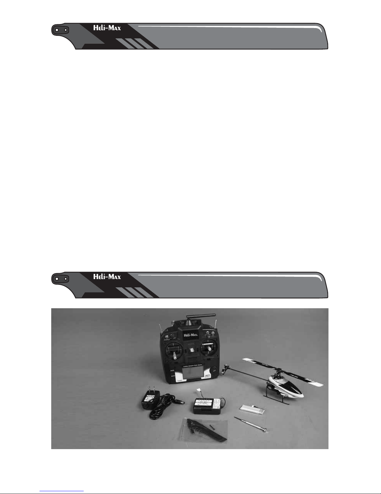
CONTENTS
CONTENTS
Required: 8 AA batteries
● Heli-Max TX 610
Transmitter and manual
● AX E100 SS/ SSL Helicopter
● 400mA h LiPo Flight Batter y
● Adjustable LiPo
Battery Charger
with wall adaptor
● Screw Driver
● Extra Blade Set
● Extra Rotor
Linkage Set
● Heli-Max TX 610
Transmitter and manual
● AX E100 SS/ SSL Helicopter
● 400mA h LiPo Flight Batter y
● Adjustable LiPo
Battery Charger
with wall adaptor
● Screw Driver
● Extra Blade Set
● Extra Rotor
Linkage Set
Page 5
5
GENERAL HELICOPTER SPECIFICATIONS
Management: Collective Pitch, 120 degree CCPM, TAGs control
Motors: Brushless main motor, brushed tail motor
Empty Weight: 47.8g (1.69oz)
Weight RTF: 6 0.1g ( 2.12oz)
Blade Length: 105mm (4.13”)
Tail Rotor Diameter: 38mm (1.5”)
Overall Length: 312mm (12.3”)
Height: 81mm (3.18”)
Width: 52mm (2.04”)
Gear Ratio: 8:1
MOTOR SPECIFICATIONS (1412 Brushless Motor)
Diameter: 14.5mm
Length: 13.6mm
Weight: 6.9g
Voltage: 3.7v
No load Current: .7 amp
KV: 14,750
CONTROLLER SPECIFICATIONS
Max current (5min): 10 amp
Thermal protection: 90˚C~120˚C
Slow Start Function: Yes
Soft cutoff: Yes
®
OPERATIONAL WARNINGS
OPERATIONAL WARNINGS
● Please allow a 10 minute cool down period after each flight so the
motor controller and motor can cool down. Failure to do so may cause
loss of control due to the controller overheating and shutting down.
● Inspect the main rotor blades and blade screws before each flight for nicks
or loose components. If any damage is found or if the blades have been
damaged, replace the blades before flying the model again.
● The motor controller has a soft cut function that will reduce the power output
to protect the flight battery. Toward the end of a flight you will notice a slight
power reduction. Land the model immediately. The flight time of the AXE100
SS/SSL can be as long as 6 minutes (Standard Hover) but this will vary
depending on your flying style.
● After a crash you must inspect all plastic parts on the helicopter for damage
before attempting to fly the model again.
● Always unplug your battery from the helicopter after use.
Page 6
6
®
TRANSMITTER (RTF Model)
TRANSMITTER (RTF Model)
Please fully read the transmitter manual included with
your helicopter to learn more about how to use and
adjust your TX610.
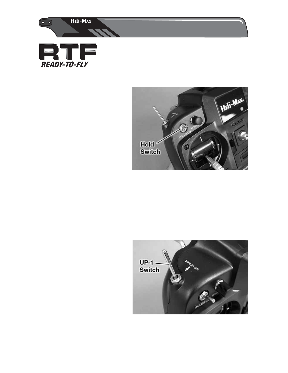
IMPORTANT TRANSMITTER FUNCTIONS
The Throttle Hold Switch (HOLD/
FLAP) is used to disable the power
output of the motor but has no
effect on the other controls. The
throttle hold function is intended
for autorotation landings off power
descent to landing; this maneuver
is really not realistic with a motor
driven tail. In addition to
autorotation the throttle hold
function can be used as a safety
switch while handling the model
since it disables power to the motor. Turn the transmitter on and set the throttle
hold switch to the on position. Now you can safely connect the flight battery
without having to worry about inadvertently moving the throttle stick once you
place the model on the ground. Verify that the idle up switch is off and the throttle
stick has been moved to its lowest position. Then, simply turn the throttle hold
off. The model is now ready to fly. Another use for the throttle hold function is
to disable the motor before a crash without having to drop the collective stick,
possibly forcing the model into the ground.
The UP-1 function is enabled and
ready to use. The UP-1 switch
(UP-1/GEAR) function is used for
aerobatics and 3D flight. If you are
a beginner to aerobatics,
remember this switch sets the
motor speed (see your TX610
manual for details) while still
allowing positive and negative
pitch control. This means if you
get confused flying, pulling the
throttle stick back WILL NOT decrease the power to the motor but rather add
power. Hence it’s a good idea to learn to use the Throttle Hold Switch when you
feel a crash is imminent!
Page 7
7
It’s also important to know that your TX610 transmitter is capable of a system
reset. (See how this is done in the TX610 Manual.) If you decide to do a system
reset, the factory setup numbers to the Heli-Max AXE100 SS/SSL are listed here.
Below are the factory default parameters (Model Memory 8) for your AXE100
SS/SSL Helicopter.
AXE100 SS/SSL / TX610 1 AILE 2 ELEV 3 THRO 4 RUDD 5 GYRO 6 PITC
Type HELI
Swash Type 90 deg
Servo Reverse (NOR/REV) N N N N N N
Dual Rates (D/R) 80/100 80/100 80/100
Exponential (EXPO) -20 -20 0
Sub Trims (S-TRM) 0 0 0
Normal Throttle Curve (N-TH) 0 50 75 85 100
Normal Pitch Curve (N-PI) 45 50 55 62 68
UP-1 Throttle Curve HOV/FLAP.T DIAL
UP-1 PITCH Curve 30 40 52 60 70
Gyro Rate (G-S) 75 (Switch Down) 24 (Switch Up)
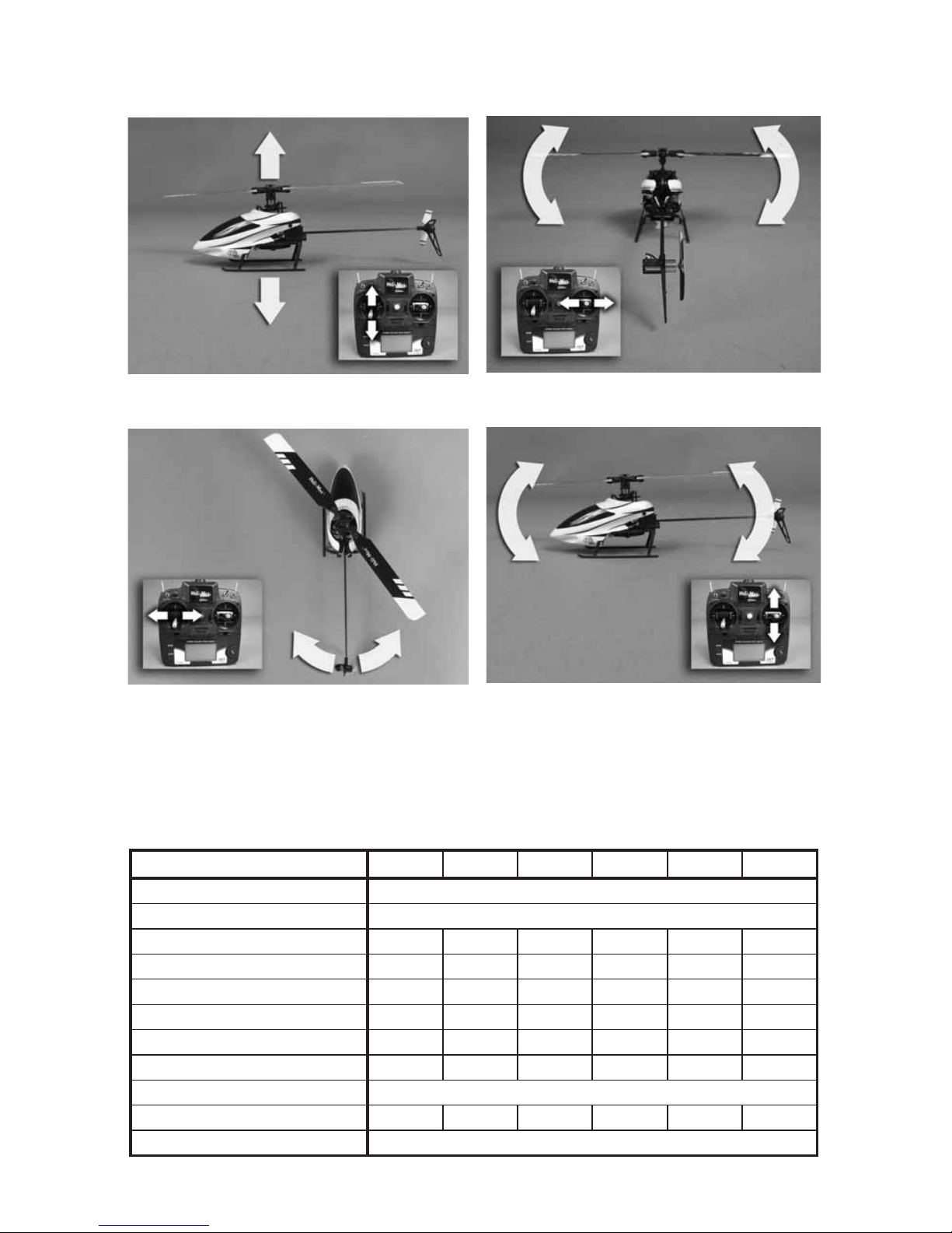
STICK CONTROLS
Throttle/Collective
Tail (rudder)
Left and right cyclic
Forward and back cyclic
Page 8
8
®
GETTING THE MODEL READY TO FLY
GETTING THE MODEL READY TO FLY
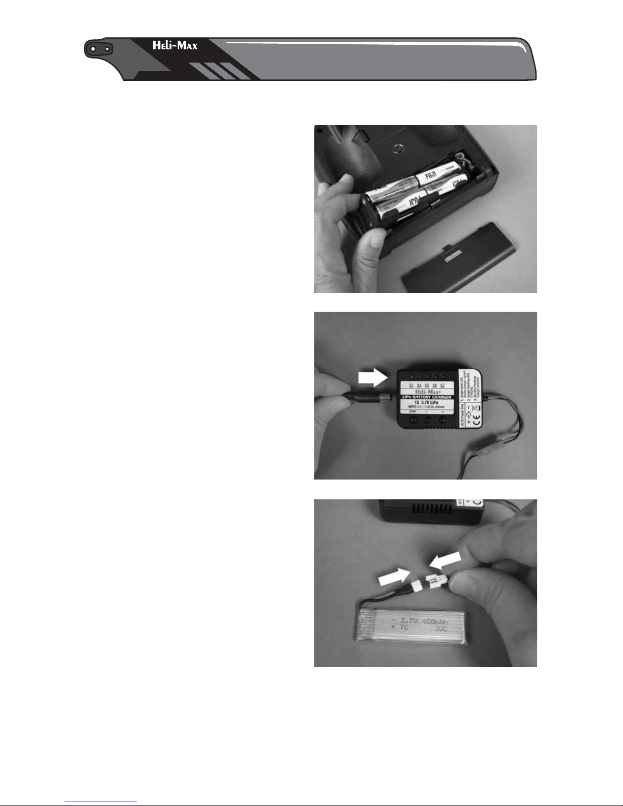
INSTALL BATTERIES IN THE TRANSMITTER
Remove the battery cover from the
back of the transmitter and install
eight “AA” batteries into the
transmitter. Double-check the
polarity of each battery before
replacing the battery cover.
CHARGE THE FLIGHT BATTERY
Plug the wall power supply into any
110V standard outlet. Plug the
remaining 4mm plug into the side of
the charger box.
The center front panel LED will light
letting you know the charger has power.
Plug the helicopter’s power battery into
the open connector of the charger. The
charger will beep twice letting you know
the battery is connected.
Page 9
9
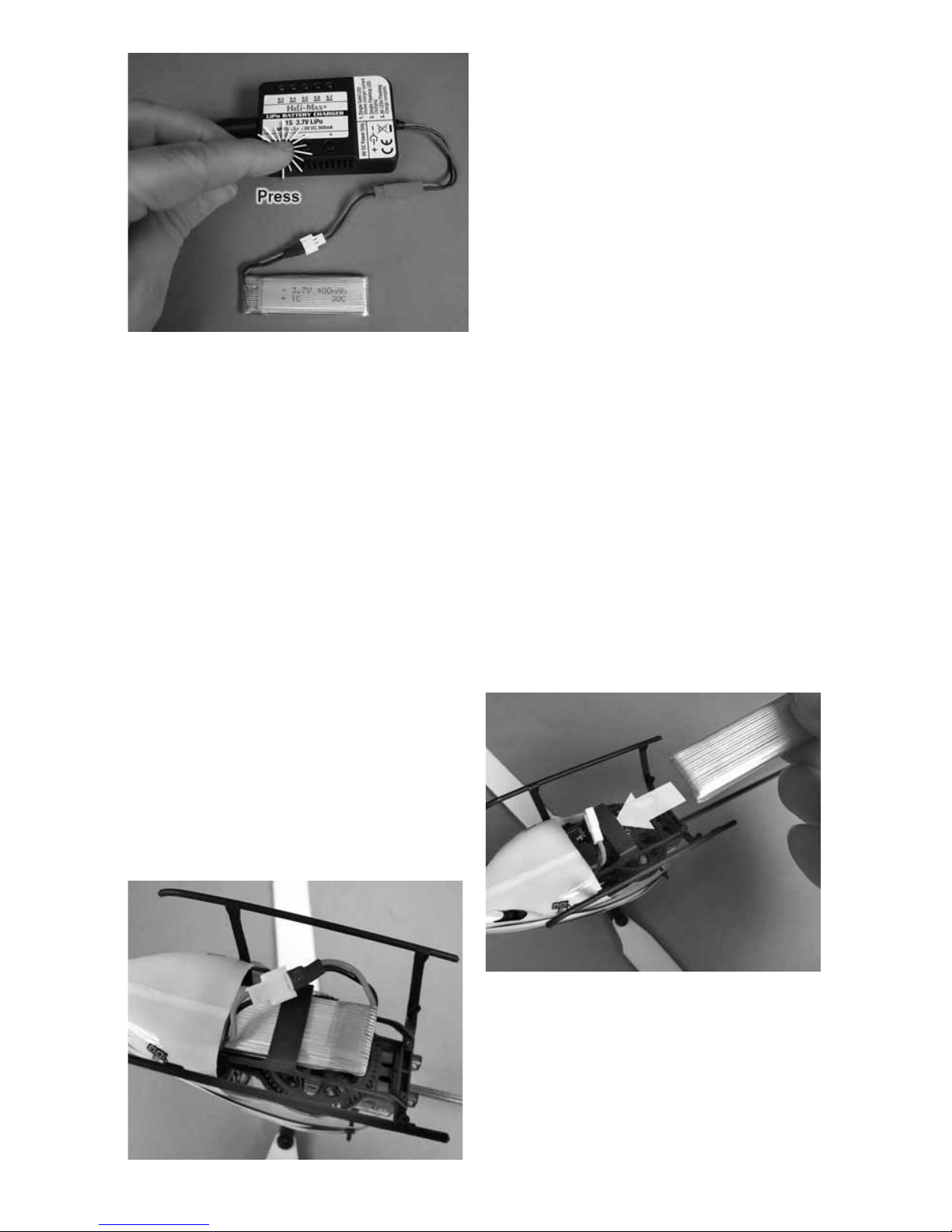
At this point you can select a slower or
faster charge rate by pressing the - or
+ buttons located on the face of the
charger. While the LED is illuminated
you will need to press the charge button.
You will hear 3 beeps and the charge
cycle will begin.
When charging is complete, all the LEDs
will flash and you will hear a steady set
of beeps coming from the unit. Unplug
the flight battery. It is now ready to use.
NOTE: Your battery charger ranges from .3AMPS to .7AMPS in .1 amp increments.
The higher this value, the faster the battery will charge. We recommend charging
on the .5AMP setting (Default).
TURN THE TRANSMITTER ON
Verify that the HOLD/FLAP and UP-1/GEAR functions are off and slide the
power switch up to turn the transmitter on. If the transmitter is turned on with
the HOLD/FLAP, UP-1/GEAR or throttle stick forward, the screen will show “3D”
or “T-H” and a warning will sound. Turn the HOLD/FLAP and UP-1/GEAR
functions off and move the throttle stick to the low position to continue. Now is
a good time to make sure the electronic trim buttons on the transmitter are
centered. We do not need to use them as the Incredible Heli-Max TAGS™ system
controls all flight center trims.
INSTALL THE FLIGHT BATTERY
Slide the battery into the helicopter.
Make sure the battery is slid all the way
to the front of the battery tray.
Make sure the battery wires don’t come
in contact with any of the rotating parts.
Page 10

10
Once the fl ight battery has been connected, always handle the
helicopter as if it has full power available. The helicopter must remain
still for the gyro to initialize properly. This process is instantaneous
after the helicopter is held still. Turning off the HOLD/FLAP switch
the helicopter is ready to go. Now is a good time to turn on the HOLD/FLAP
switch until you are ready to start fl ying.
Your AXE100 SS/SSL uses the Tactic SLT™
protocol. This means, with the simple addition of
the Tactic Anylink™ to your favorite transmitter,
you can enjoy your Heli-Max AXE100 SS/SSL
with a familiar transmitter, “YOURS”. After the purchase of your Anylink, make
sure to fully read the instructions so you understand how to properly and safely
use the Anylink system.
When using the Anylink you must make sure to follow the proper
mapping procedure for your radio system. Failing to do so could
cause an unsafe condition. How to map your transmitter, as well as
a list of compatible transmitters, is included with your Anylink. You
can fi nd this and more information on the Tactic website, www.tacticrc.com
®
LINKING
LINKING
Your AXE100 SS/SSL RTF comes with the transmitter pre-linked to the helicopter.
The Tx-R version requires you to complete this using your transmitter and an
Anylink. Also, if you need to link or re-link for any reason, here is the proper
procedure to do so.
To identify if your transmitter is linked to the helicopter, first turn your transmitter
on, remove the canopy (see removing the canopy in the maintenance section
of this manual), and view the LED closest to the link button. It should remain
steady on. If it does not and is flashing your transmitter is not linked to the
helicopter. To link the transmitter to the helicopter follow the below procedure.
1. Turn on the transmitter, making sure all the switches are in the back position
and the throttle is down.
2. Remove the canopy from the helicopter and locate the small black
button near the front of the PC board. Next to it will be an LED (flashing
if not linked).
3. Place the transmitter in close proximity to the helicopter (1 to 2 feet away).
4. Press and hold the push button for 3 seconds or until the LED remains on.
™
Page 11

11
5. Monitor the flashing LED. When it
stays on without flashing, your
transmitter is now linked to the
helicopter. Note: there is a second
LED in the center of the PCB. When
your transmitter is linked and the
helicopter held still this LED will
flicker, letting you know your
TAGS™ stabilization system is
working and ready.
TRANSMITTER SETUP GUIDELINES TO HELP YOU GET STARTED
FUTABA: You will fi nd that regardless of the Futaba system you choose, the
basic setup is the same. This includes the Futaba 6EX, 7C, T6J, TJ8 as well as
others. We have listed the setup of a Futaba T6J transmitter. It’s also worth
noting that even though the AXE100 SS/SSL uses 120 degree CCPM (Cycliccollective-pitch-mixing), with the Heli-Max TAGS system you must select the
90 degree swash arrangement. In a Futaba system this is called H-1 or 1-S
under swash type.
The setups listed are will get you going and might suit your fl ying style. If not
please feel free to make adjustments to suite your fl ying style.
AXE 100SS/SSL Futaba TJ6 1 AILE 2 ELEV 3 THRO 4 RUDD 5 GYRO 6 PITCH
Parameter (PARA) HELI
Reverse (REVR) N N R N N N
Dual Rates (D/R) 100/80 100/80 140/100
Exponential (EXPO) -10 -10 0
Normal Throttle (N-TH) 0 40 65 80 100
Normal Pitch (N-PI) 42 50 56 66 72
Idle Up Throttle (I-TH) 100 95 90 95 100
Idle Up Pitch (I-PI) 35 45 56 66 72
Throttle Hold (HOLD) ON 0%
Gyro Mixing (GYRO) ON SW A Pos 55 Pos 55
Swashplate Type (SWSH) H-1
Timer (TIMR) 5min
Page 12

12
We have also included a basic setup for Spektrum™ users as well.
AXE 100 SS/SSL / Spek DX6i AILE ELEV THRO RUDD GYRO PITC
Low 1 2 3 4 5 High 6
Type HELI
Reverse R R N R N N
Dual Rates (D/ R) 100/80 100/80 100/100
Exponential (EXPO) Pos 20 Pos 20 0
Travel Adjustment 100% 100% 100% 100% 100 % 100%
Norm Throttle 0 50 75 85 100
Norm Pitch 42 50 56 66 70
Stunt Throttle 100 95 90 95 100
Stunt Pitch 35 45 56 66 70
Throttle Hold ON 0%
Hold Pitch NULL
Gyro Mixing 70 switch up, 75 switch down
Swashplate Type 90deg
Timer 5min
Th is is a good setup for the Tactic 650
AXE100SS/SSL / Tactic 650 1 AILE 2 ELEV 3 THRO 4 RUDD 5 GYRO 6 PITC
Type HELI
Swash Type 1 Servo
Servo Rev N N R N N N
Servo Set Travel 100 100 H+125 100 100 100
Sub Trim 0 0 0 0 0 0
Dual Rate 100/ 80 100/80 100/100
Expo -20/-20 -20/-20 0/0
TH Cut Factory
TH Hold Factory
TH Curve Normal 0 NULL NULL NULL 100
TH Curve UP-1 100 NULL NULL NULL 100
PI Curve Normal -30 NULL 0% NULL +68
PI Curve UP-1 -68 NULL NULL NULL +68
Gyro +75 / +60
Throttle Mix NULL
Rev Mix NULL
Swash Ring 110
Program Mix NULL
Timer 5:00 Min
Page 13

13
®
FLYING YOUR AXE100 SS/SSLFLYING YOUR AXE100 SS/SSL
Takeoff : During your first flights it is important to have light winds. Also, if you
are flying from grass, place a rubber mat or pad down on the grass so the small
rotating parts don’t get hung up.
Turn off the hold switch and very slowly add power and observe the model.
During “spool up” It is important to note that the torque of the main blades can
cause the helicopter to rotate slightly clockwise. This is normal.
Your AXE 100 SS/SSL has the incredible Heli-Max TAGS system. The TAGS
system takes care of all center trim function the transmitter. Having said this
you do not need, or want, to move or adjust the trim buttons during flight. If you
notice any slight flight drifting give it some time. After the helicopter’s swash
and servo links “break-in” the drift will diminish.
Hovering: Once the helicopter is in the air simply try to keep the helicopter in
one spot. This will take some practice. Remember that even a light breeze will
have an effect on the stability of the helicopter, so please take your time. Be
patient and wait for a calm day.
Landing: Level the helicopter into a steady hover and slowly decrease power
until the helicopter settles onto the ground. You might notice as the helicopter
is ready to touch down it moves around a little. This is normal as the helicopter
enters ground effect. Remember to unplug the battery from the helicopter after
your flight is complete.
BASIC MANEUVERS
Once you are comfortable with hovering in one place start working on orientations.
By this we mean to say, hover the helicopter in all positions, nose to the right,
nose to the left and the nose pointing at you (nose-in). Getting good at this
fundamental discipline will allow you to progress much faster in some of the
more advanced flying maneuvers.
Slow Pirouettes: Add a small amount of tail rotor (left or right) and try rotating
the helicopter slightly sideways and see if you can hold it there. If you become
uncomfortable you will want to bring the tail back towards you. Once you are
comfortable, try moving the helicopter to the side and turning back. Then fly
back to the other side in straight lines. You can try rotating the helicopter around
360°, which is called a pirouette. The helicopter can drift during this maneuver
so make certain you have plenty of room when you first start practicing.
Forward Flight: Now it’s time to work into basic forward flight. Just take the
basic hovering maneuvers listed above and slowly fly out farther and faster
and always bring the helicopter back after one pass. Practice controlled slow
flight in close as well. The more time you spend practicing here, the easier
things will be later on.
Page 14

14
AEROBATICS
So you are getting comfortable in fast forward flight? Well, now it’s time to slowly
progress into aerobatics. Your AXE100 SS/SSL is more than capable of full
aerobatic performance. Once you are in forward flight start using the idle up
switch. This switch raises the rotor RPM and allows the blades to progress into
negative pitch for aerobatics and inverted flight.
Chandelles: Your first step is chandelles. Fly straight across in front of you
and pull up to a 45° angle. Now at the top, when the helicopter slows down to
a stop, apply left or right tail rotor to bring the nose around 180° and continue
back down the 45° angle. As you progress with the maneuver you can pull a
greater angle than 45°, but 90° would be considered a “stall turn”.
Loops: Once you become comfortable with the chandelles and stall turns it’s
time to move onto the loop. The key to the loop is to enter with plenty of speed.
Start pulling aft cyclic to enter the loop and as the model transitions to inverted
at the top of the loop pull back on the throttle (towards negative (–) collective).
This will help maintain altitude. As the model returns back to vertical add some
positive (+) collective to maintain the speed. One of the most common mistakes
made on loops is using too much negative (–) collective at the top.
Flips: Be certain to start with plenty of altitude. From an upright hover slowly
add in full forward cyclic. As the model approaches vertical, bring the collective
stick back to center. Now, as the model continues to inverted, you will need to
start adding in negative (–) collective (or pull the collective stick back towards
yourself). As the model transitions back to vertical, again bring the collective
stick back to the middle and start adding in positive (+) collective as the model
returns back to upright. It’s simply a matter of timing. The most important thing
is, do not throw the sticks around. This can cause the head speed to drop and
may cause the tail to drift.
Inverted Hovering: Keep in mind flying a helicopter inverted is difficult but
with practice it can be learned. One of the main problems is 3 out of 4 of the
controls are reversed (forward/aft cyclic, collective and tail rotor). You have to
mentally reverse these while flying. It will take some practice. Take the loop you
learned above and just hold the inverted portion for short periods of time. As
you become accustomed to the reversed controls, you will extend the time
inverted. Also, make sure you have plenty of altitude for recovery if needed.
Page 15

15
®
MAINTENANCE
MAINTENANCE
TOOLS NEEDED
● Small screwdriver (provided)
● Soldering iron
We will describe a few simple repairs
that you can do to your helicopter. We
will list them as “removing” with the
understanding that to reassemble one
just follows each step again from the
bottom up. NOTE: It’s a good idea to
keep a magnet handy to help secure
the small screws. You can also use this
magnet to “magnetize” your screwdriver; just rub the end of the screwdriver on
the magnet for a few seconds. This works nicely to keep the screws in place on
the tip of the screwdriver. TIP: we use a small piece of white paper over the
magnet to help see the screws.
REMOVING THE CANOPY
Carefully pull the back edges of the canopy outward, sliding the rubber grommets
off the pegs. Then side the canopy forward.
Page 16

16
REMOVING THE MAIN BLADES AXE SS
Using the provided screwdriver remove the main blade screw from the blade
grip. Side the blade out of the grip.
REMOVING THE MAIN BLADES AXE SSL
Using the supplied screwdriver remove
the main blade screw from the blade
grip. Carefully side the blade from the
grip and unplug the LED power wire.
Page 17

17
REMOVING THE TAIL BLADE
Hold the motor firmly and pry the tail blade off using your fingernail or small, flat
blade screwdriver. Use your finger to press the new blade in place. NOTE:
When reinstalling, do not force the blade tight against the motor.
REMOVING THE LANDING GEAR
A total of 6 screws hold the battery tray/
landing gear in place. Using the supplied
screwdriver remove the 6 screws.
REMOVING THE MAIN GEAR AXE SS
After removing the landing gear, use the supplied screwdriver to remove the
screw that holds the main gear in place. Slide the main gear away.
Page 18

18
REMOVING THE MAIN GEAR AXE SSL
After removing the landing gear, scrape
away any adhesive holding the wires to
the solder lugs. Unsolder the two wires
from the gear contact posts. Using the
supplied screwdriver, remove the screw
that holds the main gear in place. Slide
the main gear away, carefully snaking
the two wires though the center hole.
REMOVING THE MAIN SHAFT
Remove the landing gear, and remove the main gear. Using the supplied
screwdriver loosen the two screws on the lock collar. Remove the ball links that
attach the servo pushrods to the swashplate. Remove the links from the blade
grips. Slide the main shaft and head from the helicopter and remove the screw
from the head block. Slide the main shaft away. NOTE: When reassembling,
it’s important to set the shaft lash using the lock collar so as not to be too loose
or too tight.
Page 19

19
REMOVING THE FEATHERING SHAFT
NOTE: You will have to provide a second small phillips screwdriver for this step.
Remove the blades from the blade grips as described above. Place a screw
driver in the end of each blade grip and engage the screws. Unscrew the screws
and one of the two will remove. Slide the blade grips off, being very careful to
not lose any parts. Note the direction of the silver spacer washers.
REPLACING AN AFT SERVO
Remove the canopy. Remove the link from the swashplate. Unscrew the screw
from the attachment bar. Carefully place pressure on the bar back, and then
slide off the servo tabs.
Snake the wire out of the loom and then unplug the servo.
Page 20

20
REPLACING THE FORWARD SERVO
Remove the canopy. Remove the link from the swashplate. Unscrew the two
screws from each side of the servo mount. Snake the wire out of the loom and
then unplug the servo.
REMOVING THE TAIL BOOM
Remove the canopy. Unplug the connector leading to the tail motor. Snake the
wires away from the bundle. Grasp the tail boom and pull it away from the main
frame. If you find the boom hard to remove, use a drop of CA debonder on the
parts and allow that to work into the joint before you try to remove it again.
Page 21

Notes:
21
Page 22

22
16
12
14
7
23
7
13
15
19
29
29
29
20
22
1
2
3
4
6
8
9
10
11
29
29
29
29
1
29
29
18
21
17
6
5
7
®
REPLACEMENT PARTS
REPLACEMENT PARTS
Page 23

23
HMXE2102
Rubber Damper s (6 )
3
AXE100 CP/SS/SSL
HMXE2201
Main Blade (2)
6
AXE100 SS
HMXE2107
Main Shaft
299
AXE100 CP/SS
AXE100 FP/MD
HMXE2111
Servo Links (3)
12
AXE100 CP/SS/SSL
HMXE2120
Canopy Servo Mount
2915
AXE100 CP/SS/SSL
HMXM2037
1.9g Servo W / Arm
1718 19
AXE100 CP/SS/SSL
HMXE2101
Head Block
2
AXE100 CP/SS
HMXE2104
Blade Grip (2)
2975
AXE100 CP/SS/SSL
HMXE2106
Head Linkage (4)
8
AXE100 CP/SS/SSL
HMXE2109
Main Shaft Collar
2911
AXE100 CP/SS/SSL
AXE100 FP/MD
HMXE2185
Ball Link Stud (6)
17
AXE100 CP/SS/SSL
HMXE2191
Main Frame
714
AXE100 SS/SSL
HMXE2103
Blade Grip Spacers (6)
4
AXE100 CP/SS/SSL
HMXE2100
Feather Shaf t (2)
291
AXE100 CP/SS/SSL
HMXE2116
Bearing Set (6 )
7
AXE100 CP/SS/SSL
HMXE2117
Elevator Servo Mount
2913
AXE100 CP/SS/SSL
HMXE2190
Swashplate
10
AXE100 SS/SSL
HMXG8031
Brushless Motor
16 29
AXE100 SS/SSL
Page 24

24
26
27
28
29
Page 25

25
Tail Rotor (Gold)
HMXE2199
AXE100 SSL
HMXE2114
Canopy (Yellow)
AXE100 CP
HMXE2152
Tail Rotor (Black)
AXE100 FP
HMXE2121
Double Stick Tape (4)
21
AXE100 CP/SS/SSL
HMXE2189
Screw Set
29
AXE100 SS
HMXG8033
Tail Boom W / Motor
26
AXE100 SS
HMXE2198
Canopy (Gold)
AXE100 SSL
HMXE2188
Tail Rotor (Green)
AXE100 SS
HMXE2204
Main Gear
2923
AXE100 SS
HMXP1010
400mAh Lipo Battery Pack
28
AXE100 SS/SSL
HMXM2042
TAGS Control Board
20 21
AXE100 SS
HMXE2187
Canopy (Green)
AXE100 SS
HMXE2122
Tail Rotor (Yellow)
AXE100 CP
HMXE2118
Servo Arm W / Link ( 3)
1719 18
AXE100 CP/SS/SSL
HMXE2192
Landing Skid W /Screws
27 29
AXE100 SS/SSL
HMXM2043
10A Control Board
22
AXE100 SS/SSL
HMXE2124
Assembled Rotor Head
AXE100 CP/SS
Page 26

26
30
21
34
36
35
34
35
37
38
31
33
32
AXE100 SSL
Page 27

27
HMXE2197
Main Gear W / Contact Plate
30
AXE100 SSL
HMXE2196
LED Plate Contacts
33
AXE100 SSL
HMXE2194
Main Shaft
w/ Rotor Head and Board
36
AXE100 SSL
HMXE2193
Rotor Blades W / LEDs
34
AXE100 SSL
HMXG8032
Tail Boom W / Motor and LED
31
AXE100 SSL
37
HMXE2200
Screw Set
35
AXE100 SSL
HMXM2044
TAGS Control Board
32
AXE100 SSL
38
Page 28

28
9
8
41
1
3
4
42
42
40
7
39
JST
12
HMXE2123
Bat ter y Plug Adaptor
HMXE2051
CNC Metal Blade Grips
40
AXE100 CP/SS/SSL
HMXE2050
CNC Me tal Head Block
39
AXE100 CP/SS/SSL
HMXE2053
Screw Set CNC Rotor Head
42
AXE100 CP/SS/SSL
CNC Me tal S washplate
HMXE2052
41
AXE100 CP/SS/SSL
CNC Rotor Head (Ass embled)
HMXE2054
AXE100 CP/SS/SSL
HMXE2186
Bulle t Rotor Blade (2 )
AXE100 ALL
 Loading...