

Page 1

© 2013 Hobbico®, Inc.
NOTICE
AXE100 CX
Instruction Manual
The instruction manual, warranties and other associated documentation are subject
to change without notice. Hobbico assumes no responsibility for inadvertent errors
in this manual.
Heli-Max products are to be used by ages 14 and over.
HMXE0818 Axe 100
HMXE0828 Axe 100
CX RTF
CX Tx-R
®
Page 2
2
®
INTRODUCTION
INTRODUCTION
Thank you for purchasing the Heli-Max AXE 100 CX Helicopter. We are certain
you will get many hours of enjoyment out of this model. If you should have any
questions or concerns please feel free to contact us at: helihotline@hobbico.com.
For the latest technical updates or manual corrections visit the Heli-Max web site
at www.helimax-rc.com. If there is any new technical information, changes or
important updates to this model a “tech notice” box will appear on the 100 CX
product page. Click the “tech notice” box to learn more about this important update.
All controls and responses from the AXE 100 CX are described with the tail pointing
directly toward you. This is the best way to fl y in the beginning since it keeps the
control inputs oriented in the same direction as the model will respond.
When you see this symbol, please pay special attention and
heed all warnings regarding the information within.
®
TECHNICAL SUPPORT
TECHNICAL SUPPORT
● Please note that we cannot provide any information on the pricing that you
will fi nd in your local retailer’s store for any products.
● If you need technical support or have any question, you can reach us by one
of the following means. When contacting us, please include the name of the
product you are referring to, its stock number and as much information about
your question or issue as possible.
● For support outside the U.S. or Canada, please contact the distributor in your
country. If unable to contact the appropriate distributor, please contact us.
However, we are unable to respond to emails in languages other than English.
EMAIL: helihotline@hobbico.com. Please be sure to list your full email
address (ex: johndoe@aol.com) as well as at least one other means of
daytime contact in your email.
TELEPHONE: 1-217-398- 8970, Select option 5. Available Monday-Friday,
8am-5pm U.S. Central Time.
FAX: 1-217-398-7721. Please be sure to include a daytime telephone
number or return fax number so that we can contact you.
Page 3
3
REGULAR MAIL: If you prefer, we can always respond with a regular
mailed letter. Simply write to us, including a brief explanation of your
problem or question along with the product name.
®
WARRANTY
WARRANTY
Heli-Max guarantees this kit to be free from defects in both material and
workmanship at the date of purchase. This warranty does not cover any component
parts damaged by use or modification. In no case shall Heli-Max’s liability
exceed the original cost of the purchased kit. Further, Heli-Max reserves
the right to change or modify this warranty without notice. In that Heli-Max has
no control over the final assembly or material used for final assembly, no liability
shall be assumed nor accepted for any damage resulting from the use by the
user of the final user-assembled product. By the act of using the user assembled
product, the user accepts all resulting liability. If the buyer is not prepared to
accept the liability associated with the use of this product, the buyer is
advised to return this kit immediately in new and unused condition to the
place of purchase.
To make a warranty claim, Hobby Services 217-398-0007
send the defective part or 3002 N. Apollo Dr., Suite 1
item to Hobby Services Champaign, IL 61822
at this address. USA
Include a letter stating your name, return shipping address, as much contact
information as possible (daytime telephone number, fax number, e-mail address),
a detailed description of the problem and a photocopy of the purchase receipt.
Upon receipt of the package the problem will be evaluated as quickly as possible.
Page 4
4
®
CONTENTS
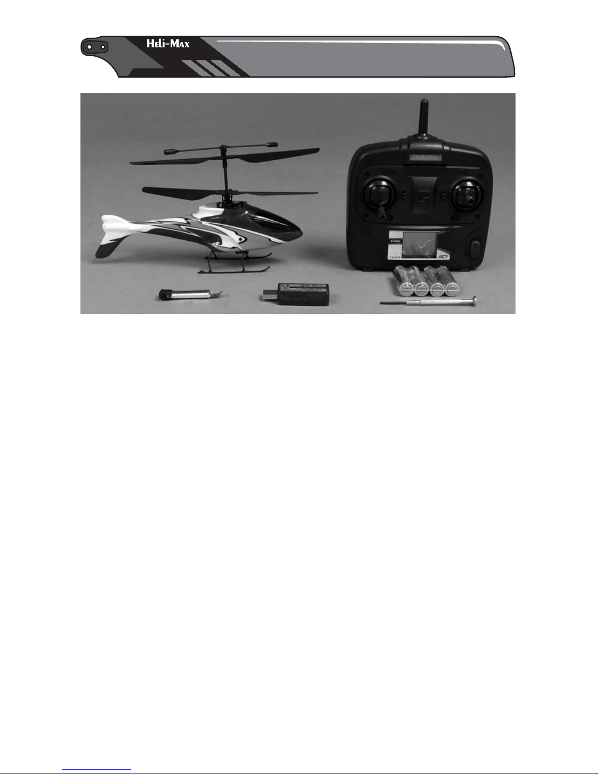
CONTENTS
AXE 100 CX Helicopter
TX 410 4-Channel SLT Transmitter
Heli-Max 150mAh LiPo Battery pack (1)
USB Charger
Small Phillips screwdriver
AA Batteries (4, not included in the Tx-R version.)
SPECIFICATIONS
Rotor Diameter: 190mm (7.48")
Empty Weight: 28.2g (.995 oz)
Weight RTF: 31.9g (1.25 oz)
Fuselage Length: 220mm (8.66")
Height: 126mm (4.96")
Width: 45mm (1.8")
AXE100 CX RTF
AXE100 CX RTF
Page 5
5
®
OPERATIONAL WARNINGS
OPERATIONAL WARNINGS
● Failure to follow these safety precautions may result in injury to yourself
and others.
● Your AXE 100 CX should not be considered a toy. It should be treated as a
working model that functions much like a full-size helicopter. Keep your face
and body as well as all spectators away from the rotating blades whenever
the battery is connected. Keep loose clothing, shirt sleeves, ties, scarfs, long
hair or loose objects such as pencils or screwdrivers that may fall out of shirt
or jacket pockets away from the rotors. The spinning blades of a model of
this type can cause injury.
● When choosing a fl ying site stay clear of buildings, trees and power lines.
AVOID fl ying in or near crowded areas.
● DO NOT fl y close to people or pets. Maintain a safe distance from the helicopter.
● Do not alter or modify the model. Doing so may result in an unsafe or unfl yable
model.
● When repairs are necessary you should correctly install all components so
that the model operates properly on the ground and in the air. Please check
the operation of the model before every fl ight to insure that all equipment is
operating and that the model has remained structurally sound.
● Please allow a 10 minute cool down period after each fl ight so the motor
controller and motors can cool down. Failure to do so may cause loss of
control due to the controller overheating and shutting down.
● Inspect the rotor blades before each fl ight for nicks. If the blades have been
damaged, replace them before fl ying the model again. Be sure to check
linkages or other connectors often and replace them if they show any signs
of wear or fatigue.
● After a crash you should inspect all plastic parts on the helicopter for damage
before attempting to fl y the model again.
Page 6
6
®
BATTERY CHARGING
BATTERY CHARGING
● Please read and understand the following regarding the usage of LiPo
batteries.
● Through the use of the included LiPo battery you have assumed all risk and
responsibility regarding a LiPo battery and its use.
● ALWAYS unplug your battery from the helicopter after use.
● ALWAYS recharge the batteries before storage to prevent the voltage from
dropping below the 3.0 volts.
● It’s best to store your batteries charged and at room temperature.
● Never disassemble, puncture or modify the battery pack in anyway.
● Never allow the battery temperature to exceed 150° F [65° C].
● If your battery begins to swell or becomes damaged in any way, stop using
it. Contact Hobby Services at 217-398-0007 to learn the proper way to dispose
of your battery.
● Only use the included charger with the included LiPo battery. Do not attempt
to use the provided charger with NiCd, NiMH or batteries with other chemistries.
● Do not leave the charger unattended while in use and always charge your
battery in a fi re-resistant location.
● Disconnect the battery and remove input power from the charger immediately
if either becomes hot!
● Do not allow water or other foreign objects to enter the charger. Keep the
charger away from moisture and do not submerge in water.
● Please keep all electronic components out of the reach of children!
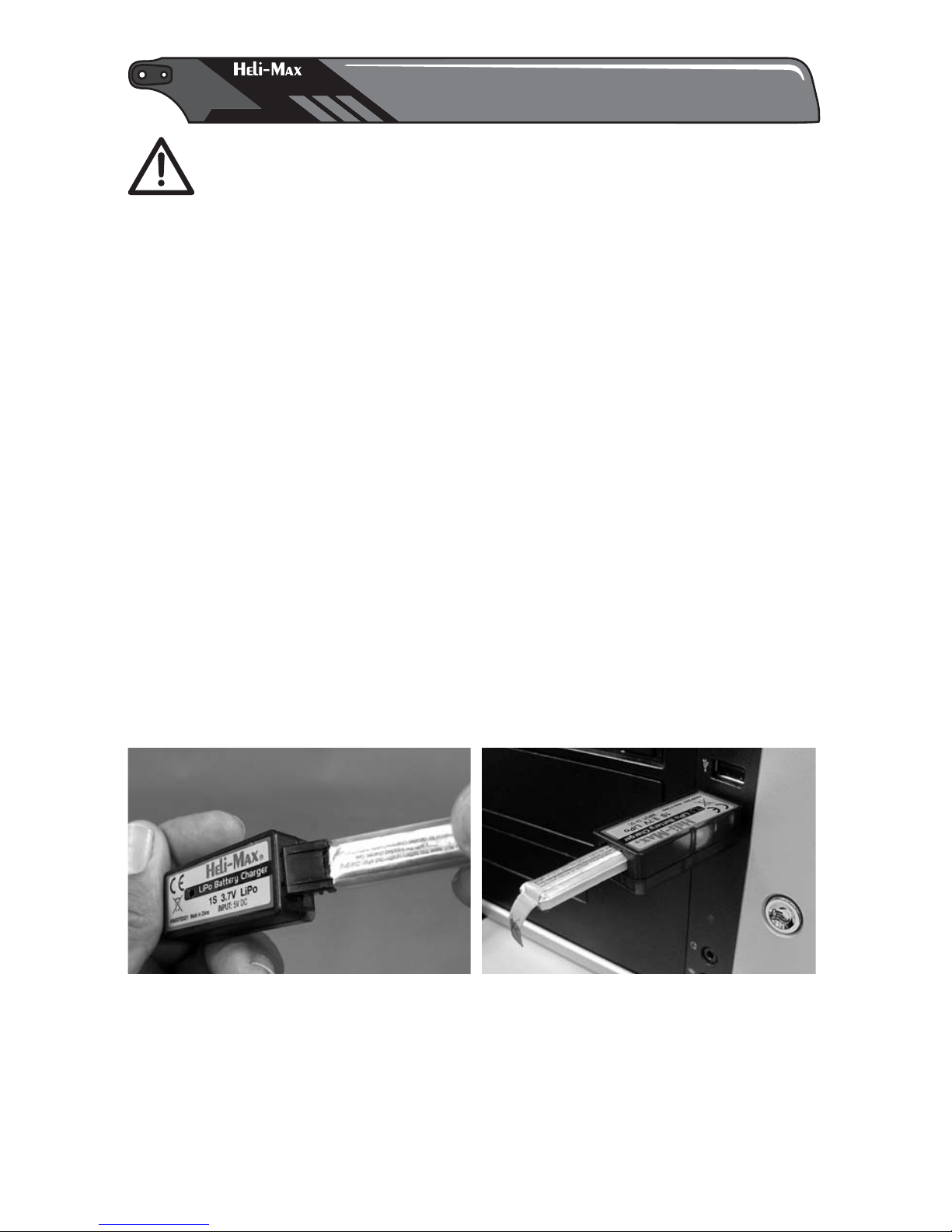
Plug charger into a USB port. A steady red light will glow letting you know the
battery is charging. The light will flash slowly when the charge is complete.
Remove the battery from the charger. Under normal operating conditions, the
battery may take up to 60 minutes to recharge. Never leave the battery attached
to the charger after charging is complete.
NOTE: A fast flash indicates a charge error. This is usually an indication that
your battery is defective and should be replaced.
Page 7

7
WARNING!! The charger supplied with the Heli-Max AXE 100 CX
helicopter contains protective circuitry. If you experience any
diffi culties while charging the battery, please disconnect the battery
from the charger and unplug the charger from the power source.
Allow the battery and charger to rest for two hours as this will allow the charge
protection circuit to reset. If this issue re-occurs during normal use, please
contact our Technical Support Department for assistance.
®
TRANSMITTER (RTF Model)
TRANSMITTER (RTF Model)
Please fully read the transmitter manual included with
your helicopter to learn more about how to use and
adjust your TX410.
TRANSMITTER SETUP AND CONTROLS
Remove the battery cover from
the back of the transmitter and
install the four “AA” batteries.
Double-check the polarity of each
battery before replacing the
battery cover.
Turn the transmitter on and make
sure that there is a blue light
behind the Heli-Max panel at the
top of the transmitter. The LCD
screen should be on with a throttle
position indicator and other
information.
The transmitter can now be turned
off until the model is ready for
flight.
Page 8

8
DUAL RATES
The transmitter has a dual rate
function. This feature toggles
between a flight mode that reduces
the model’s range of motion to make
the AXE 100 CX easer to fly and one
that allows the full range of motion
so the AXE 100 CX can fly in a more
aggressive manner. To toggle
between these two flight modes,
press down on the right control stick
and release it. When the transmitter
is in low rates, the ellipse in the lower
center of the LCD screen will show a half ellipse and emit a single low pitch
single beep. For high rates, the ellipse will be complete and the transmitter
will emit a single high pitch beep.
Page 9

9
SERVO REVERSING
This transmitter uses the Tactic SLT protocol and can be used with other
SLT receivers. In those applications, it may be necessary to reverse the
servo travel direction as follows:
With the transmitter OFF, push and “hold”
the rudder trim button to the right and
the throttle trim button down. Then turn
ON the transmitter.
Let go of the trim buttons and you will
see 1-1 or 1-0 displayed. The first Digit
is the channel number. To change the
channel you want to reverse, push down
on the right stick. To reverse the travel
direction, push the elevator trim button
up or down so the second number
changes. The V-Cam travel direction
settings should be “1” for all channels.
To confirm the change and exit to normal
operation, push down on the left stick.
The changes will not be saved if the
power is turned off before the left stick
assembly is pushed down.
Page 10

10
®
TRANSMITTER (Tx-R Model)
TRANSMITTER (Tx-R Model)
Your AXE 100 CX uses the Tactic protocol. With the
simple addition of the Tactic Anylink™ to your favorite
transmitter, be it Futaba®, JR®, Spectrum® or other
compatible system, you can fly your Heli-Max AXE 100
CX with a familiar transmitter. Any other SLT compatible aircraft transmitters
like the Tactic TTX402/TTX403 can also be used with the 100 CX.
The following setup guides for Futaba, Spektrum, and Tactic systems should
work for most transmitters that are currently available. You may find that you
need to set the servo travel for the throttle channel to maximum so the ESC on
the AXE 100 CX will arm.
AXE 100 CX Futaba
Type
Swash
Reverse (REVR)
Dual Rates (D/R)
Exponential (EXPO)
Timer (TIMR)
AILE
1
ELEV THRO RUDD
234
HELI
7 Min
NNNN
140/100 140/100 140/100
–10 –10 –10
H-1
AXE 100 CX Spektrum
Type
Swashplate Type
Reverse
Dual Rates (D/R)
Exponential (EXPO)
Timer
THRO
1
AILE ELEV RUDD
234
HELI
7 Min
RRRR
100/80 100/80 100/80
+10 +10 +10
90 degree
AXE 100 CX Tactic TTX 650
Type
Swash
Reverse (REVR)
Dual Rates (D/R)
Exponential (EXPO)
Timer (TIMR)
AILE
1
ELEV THRO RUDD
234
HELI
7 Min
NNNN
100/80 100/80 100/80
–10 –10 –10
1 Servo
Please verify that the servos respond to the controls as described in the next
section of the manual. You may need to reverse one or more channels to make
the servos respond correctly.
™
Page 11

11
®
PREFLIGHT PROCEDURES
PREFLIGHT PROCEDURES
Electric motors are very dangerous. Do not work on the model
while the fl ight battery is plugged in as interference may cause
the main rotor blades to spin, possibly causing injury.
● Examine the model for any loose screws and damaged parts. Make sure that
the linkage and the rotor blades are not loose.
● Turn on the transmitter. Check the battery charge indicator to make sure that
the transmitter battery will have enough power for your fl ying session.
Install the flight battery by sliding
the battery into the battery tray.
Place the helicopter on a flat
surface and wait a few seconds
to allow the control board to
calibrate. When you hear the
servos move, the board is linked
to the transmitter. Move the right
stick to the right and verify that
the left servo moves up in
response. When the right stick is
pulled back, the right servo should
rise. Slowly advance the throttle to test the motors. While the motors are spinning
slowly, move the rudder control left and right. The nose of the helicopter should
respond by moving the same direction as the left stick. Reduce the throttle af ter
you have verified that all the controls are working properly. Move to a safe
distance away from the model when you are ready to take off.
®
FLYING YOUR AXE 100 CX
FLYING YOUR AXE 100 CX
TAKEOFF
During your first flights it is important to have light winds if you are flying
outside. Also, if you are flying from grass or thick carpet, please use a
rubber mat or pad to provide a level area for take-off and landing.
HOVERING
Once the helicopter is in the air simply try to keep the helicopter in one spot.
If you are flying outside, remember that the wind has a big effect on the stability
of the helicopter.
Page 12

12
LANDING
Level the helicopter into a steady hover and slowly decrease power until the
helicopter settles onto the ground. You might notice as the helicopter is ready
to touch down it moves around a little. This is normal as the helicopter enters
ground effect.
BASIC MANEUVERS
Once you are comfortable with hovering at different orientations and landing,
it’s time to move on to more advanced maneuvers.
Slow Pirouettes: Add a small amount of left or right rudder to rotate the
helicopter slightly sideways and practice holding it in that position. If you
become uncomfortable bring the tail back towards you. Next, rotate the
helicopter so one side is facing you. Practice holding it in this position while
fl ying in all four directions. When you are comfortable with these exercises,
bring the model to hover and practice rotating the helicopter around 360°,
which is called a pirouette. The helicopter can drift during this maneuver so
make certain you have plenty of room when you fi rst start practicing.
Nose-In Hovering: After pirouettes it’s time to move on to nose-in hovering.
The best bet is to wait for a calm day. Take off and climb to 15 feet, practice
half pirouettes from tail-in to nose-in hovering, and try to lengthen the delay
between transitions. This will allow you to practice nose-in and still give you
a chance to get out of trouble. As you improve you’ll remain nose-in for longer
periods of time.
Forward Flight: Now it’s time to work into basic forward fl ight. Just take the
basic hovering maneuvers listed above and slowly fl y out farther and faster
and always bring the helicopter back after one pass. Practice controlled slow
fl ight in close as well. The more time you spend practicing here, the easier
things will be later on.
The ESC on the AXE 100 CX has a soft cut function that will reduce the power
output to protect the fl ight battery from damage. Toward the end of a fl ight, if
you notice a power reduction, land the model immediately and re-charge the
battery. Your fl ight time should be at least 6 minutes but this will var y depending
on your fl ying style.
POST FLIGHT PROCEDURES
● Remove the battery from the helicopter. While the battery is cooling, turn off
the transmitter and check the model again for any loose or damaged parts.
● Charge the batteries before the model is to be put away. If the model is being
stored for a long time period, stop the charging process at half the normal
charge time. The batteries should be charged again after 4 months and before
the model is to be used again.
Page 13

13
®
MAINTENANCE
MAINTENANCE
We will describe a few simple repairs that you can do to your helicopter. We will
list the steps needed to remove the part with the understanding that to reassemble,
one just follows the steps in the reverse order. NOTE: It’s a good idea to use a
small tray with a magnet below it to help secure the small screws. You can also
use a magnet to “magnetize” your screwdriver; just rub the end of the screwdriver
on the magnet for a few seconds. This will be help to keep the screws in place
on the tip of the screwdriver.
REMOVING THE FUSELAGE
There are two pegs on each side of the fuselage that hold the two sections of
the fuselage to the frame. Carefully push the back edges of the canopy outward
and slide the rubber grommets off the pegs. Then slide the canopy forward to
remove it from the frame. Follow the same procedure to loosen the rear fuselage
and pull the frame forward to remove it.
REMOVING THE MAIN BLADES
Using the provided screwdriver remove the screw on each side of the blade
assembly. There is a small key that is molded on the hub of the blade. Twist the
two blades to get the keys out of the slots in the base of the other blade. Then
Page 14

14
pull the blades apart. When installing the rotor blades, please keep in mind that
the lower set rotates clockwise and the upper set rotates counter-clockwise.
REMOVING THE LANDING GEAR
The landing gear has two pegs that hold
it onto the helicopter frame. Gently pull
down to remove the landing gear. There
is a plug on the wire to the board that
needs to be disconnected if the landing
gear is to be removed from the control
board.
REPLACING THE FLYBAR
To remove the flybar, push out the pin
that secures it to the rotor shaft with a
small screwdriver. You will need to use
a pair of pliers to pull the pin out of the
flybar. Pop the connecting link off and
remove the flybar.
REMOVING THE MAIN GEARS
The landing gear will have to be removed to allow access to the main gears.
Use the supplied screwdriver to loosen the screws that hold the lower main gear
in place and slide it off the inner rotor shaft. The upper main gear can be pulled
off the outer rotor shaft without removing any other parts.
Page 15

15
REMOVING THE MAIN SHAFTS
The inner rotor shaft can be removed after the lower main gear is loose. If this
part is to be replaced, the upper rotor blade and flybar will have to be removed
and transferred to the new rotor shaft.
Before the outer rotor shaft can be removed, the links from the servos need to
be removed from the swashplate. The outer rotor shaft can be removed from the
frame. If the rotor shaft is being replaced, transfer all the parts to the new shaft.
The screws that hold the rotor hub
should be 35mm from the top of the
outer rotor shaft.
Do not tighten the screw on the collar
until both rotor shaft assemblies have
been installed on the frame. While
pushing up on the main gears and down
on the collar to remove any free play,
tighten the set screw for the collar.
REPLACING MOTORS
Carefully spread the clips that secure
the motor to the frame. When the clips
are clear of the back of the motor, push
the motor up and out of the frame.
Please note the position of the wires
before unplugging the defective motor.
REPLACING CONTROL BOARD
Please record the color of the top wire
on both motor connectors before
unplugging the motors from the board.
Remove the links from the servo
assemblies. Finally, there are two small
screws on the front of the board that
need to be removed so the board can
be replaced.
Page 16

19
16
®
REPLACEMENT PARTS
REPLACEMENT PARTS
1 HMXE2301 Flybar
2 HMXE2302 Flybar Pin
3 HMXE2303 Inner Shaft
4 HMXE2304 Outer Shaft
5 HMXE2306 Rotor Blade Set
6 HMXE2307 Rotor Hub
7 HMXE2308 Screw Set
8 HMXE2309 Linkage Set
9 HMXE2310 Swashplate
10 HMXE2311 Collar Set
11 HMXE2312 Main Frame
12 HMXE2313 Motor Set
13 HMXE2314 Bearing Set
14 HMXM2055 E-Board
15 HMXE2315 O-Ring Set
16 HMXE2316 Main Gear Set
17 HMX P10 07 3.7V 1S LiPo Batter y
18 HMXE2317 Landing Skid
19 HMXE2318 Canopy Set
HMXJ2024 410 SLT Transmitter
HMXP2021 1S USB Charger
Page 17

5
1
7
5
5
7
9
7
11
7
3
4
7
8
12
13
8
15
14
11
7
7
8
2
5
16
10
10
8
13
17
18
6
17
Page 18

Notes:
18
Page 19

Notes:
19
Page 20

20
 Loading...