

Page 1
hilft!
Wir sind für Sie da!
Schnelle Hilfe 24/7
www.held-hilft.de
Ersatzteil-Sofort-Hilfe:
0571-7983810
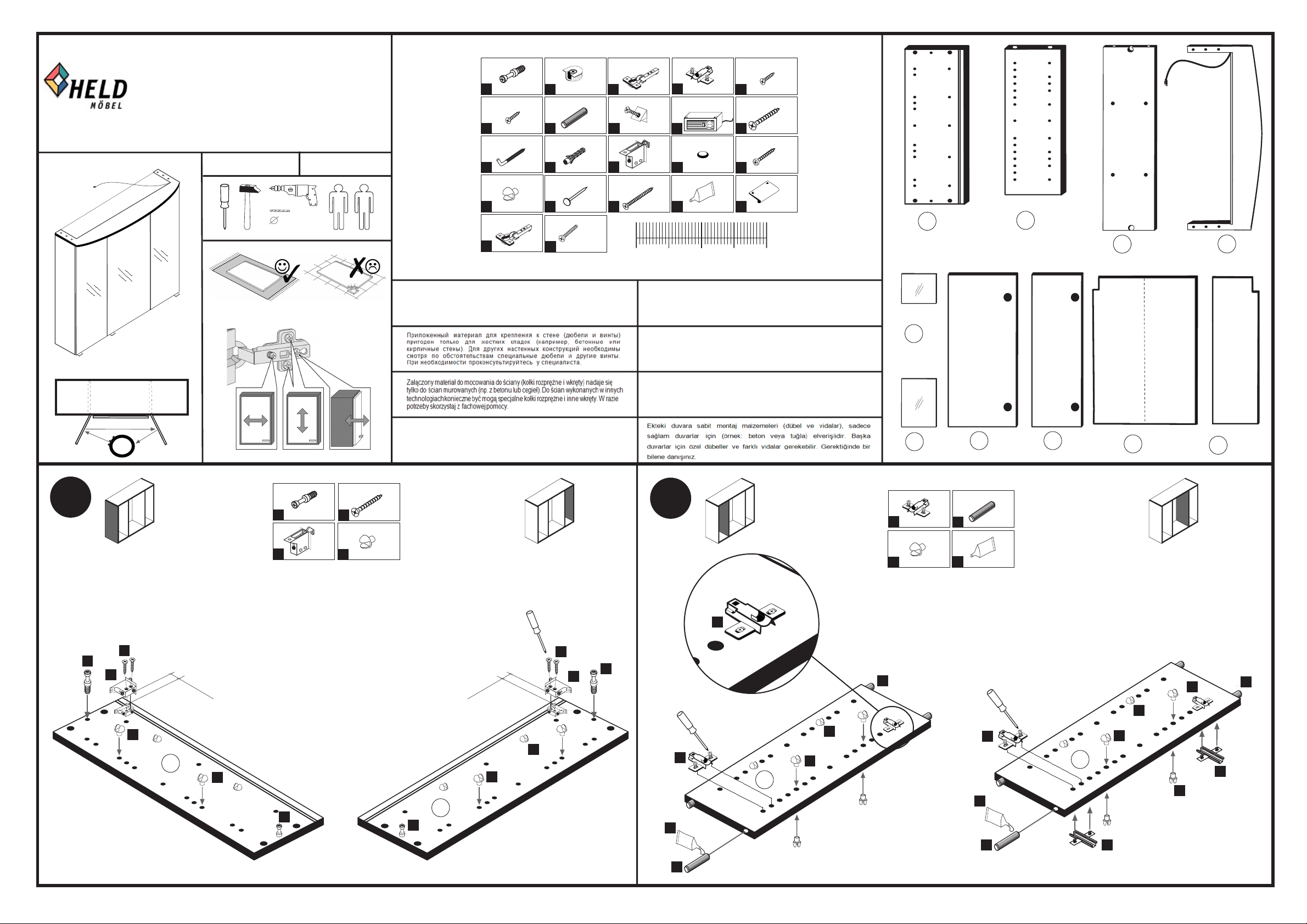
88081.531
5 mm
05-09-2017
1
6
11
16
ungedämpft
21
4 x
2802
3,5 x 15
12 x
2804
5,8 x 55
2 x
2840
24 x
2819
3 x
1507
gedämpft
4 x
2
7
12
17
21
2801
8 x 30
16 x
2861
8 x 30
2 x
2842
25 x
2862
20 x
2832
3
8
13
18
3 x
4
1506
6 x
9
2552
2 x
14
2843
4,0 x 65/70
2 x
19
0 10 20 30 40
6 x
1614
1 x
6 x
2865
1 x
2863
10
15
15
20
3,0 x 15
6 x
5
15
2803
4 x 30
4 x
2812
3 x 25
6 x
2794
3 x
1098
24
2 x
25
2 x
26
2 x
27
1 x
1
3D-Effekt
Das beigefügte Wandbefestigungsmaterial (Dübel und Schrauben) eignet sich nur für
festes Mauerwerk (z.B.: Beton- oder Ziegelwände). Für andere Wandaufbauten sind
eventuell Spezialdübel und andere Schrauben notwendig. Ziehen Sie gegebenfalls
eine Fachkraft zu Rate.
The accompanying wall mounting hardware (anchors and screws) is suitable only
for solid masonry (eg concrete or brick walls). For other wall structures are
possibly special anchor bolts and other necessary. Tighten if necessary, an expert.
4 x 30
4 x
1
13
2802
2 x
2843
10
16
4 x
2812
8 x
2819
De begeleidende wandmontage hardware (pluggen en schroeven) is alleen geschikt
voor massief metselwerk (bijvoorbeeld beton of bakstenen muren). Voor andere
muur structuren zijn eventueel bijzondere ankerbouten en andere noodzakelijke.
Draai indien nodig, een deskundige.
Le mur d'accompagnement matériel de montage (chevilles et les vis) ne convient
que pour la maçonnerie solide (par exemple en béton ou des murs de briques).
Pour les structures de mur d'autres sont peut-etre spéciale boulons d'ancrage et
d'autres nécessaires. Serrer le cas échéant, un expert.
Il muro di accompagnamento hardware di montaggio (tasselli e viti) è'e adatto
solo per muratura piena (ad esempio calcestruzzo o muratura). Per le altre strutture
murarie sono forse speciali bulloni di ancoraggio e necessari di altri. Serrare se
necessario, un esperto.
2
28
4 x
30
29
2 x
6 x
4
16
1614
16 x
2819
7
19
1 x
8 x 30
8 x
2861
1 x
2863
31
2 x
32
1 x
33
1 x
4
4
1
10
13
16 mm
16 mm
16
24
16
1
24
1
16
10
13
1
7
oben
16
16
16
4
16
4
25
16
4
oben
4
8
7
25
19
19
7
7
4
16
Seite 1 von 2
Page 2
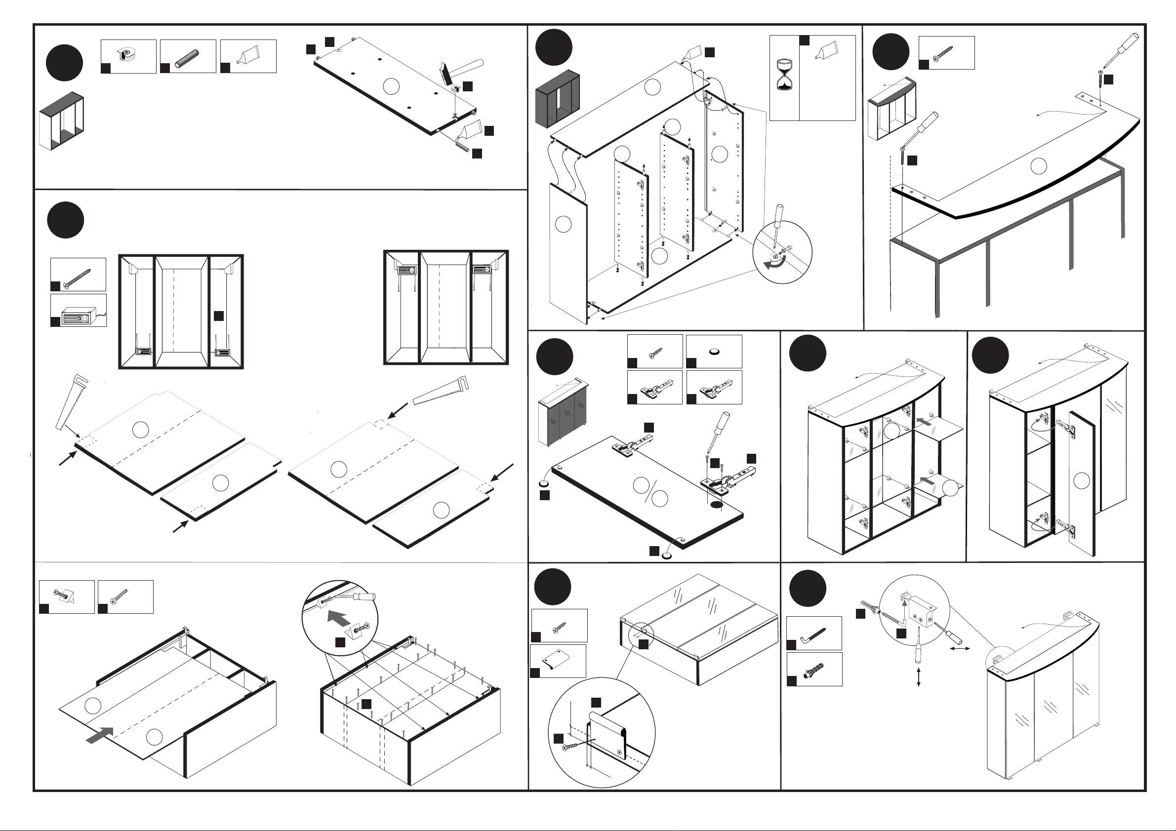
88081.531
8 mm
5 mm
3
5
18
9
4,0 x 65/70
2 x
2795
1 x
8 x 30
4 x
2
2801
7
8 x
2861
19
Variante 1: Trafomontage unten
18
Bitte nur einen Ausschnitt aussägen. (Montagevariante)
32
2
1.
7
Variante 2: Trafomontage oben
1 x
2863
Die Montage der elektrischen
Teile und Verbindungen sind
unter Berücksichtigung der
VDE 0100 Teil 701 von einer
Fachkraft des Elektrohandwerks vorzunehmen.
Sie können die Position der
Trafobox frei wählen.
Sägen Sie an der ausgewählten
Position eine Aussklinkung für
die Kabel aus.
26
2 x
19
4
2
19
7
24
25
7
26
6
gedämpft
3
25
26
3,5 x 15
12 x
2804
3 x
1506
19
24
14
ungedämpft
21
6 x
2865
3 x
1507
20 min.
8
8
D Leim
GB Glue
NL Lijm
PL Klej
TR Tutkal
F Colle
I Colla
1 x
2863
6
15
15
15
15
3 x 25
6 x
2794
9
27
15
15
11
3
29
Variante1
Trafomontage unten
6 x
8
2552
21
5
33
20 x
2832
29
32
33
2.
32
6
14
33
30
31
14
10
3,0 x 15
6 x
8
21
5
20
2803
3 x
1098
20
5
5
21
28
31
11
2 x
2 x
12
11
11
5,8 x 55
11
12
2840
8 x 30
2842
2.
1.
Seite 2 von 2
Page 3

D PL
Wichtige Sicherheitshinweise Ważne wskazówki dotyczące bezpieczeństwa
Die Installation Ihrer neuen Leuchte darf ausschließlich von autorisierten Fachpersonen durchgeführt werden Ta Instalację nowej lampy mogą przeprowadzać wylącznie autoryzowani instalatorzy
GB SK
Important safety instructions Dôležité bezpečnostné upozornenia
The installation of your new luminaire may only be carried out by authorized specialists. Inštaláciu lampy smú vykonať výhradne autorizovani
FR HU
Consignes de sécurité importantes Fontos biztonsági utmutatások
La L'installation votre nouveau luminaire doit uniquement étre réalisée par des spécialistes autorisés Az On Új lámpájának beszerelését kizárólag hivatalos szakember végezheti el
IT RO
Importanti disposizioni di sicurezza Instrucțiuni de siguranță importante
l'installazione della il loro nuovo lampada può essere eseguita solo ed esclusivamente da personale tecnico autorizzato. Instalarea noii dumneavoastră lămpi este permisă exclusiv specialiștilor autorizați
NL
Belangrijke veiligheidsaanwijzingen Önemli güvenlik uyarıları
De installatie van de nieuwe lamp moet worden uitgevoerd door vakbekwame personen worden uitgevoerd. Yeni lamba montajı yetkin kişiler tarafından yapılmalıdır
TR
CZ
Důležité bezpečnostní pokyny важная информация по технике безопасности
Instalaci nových svitidel smí provádět pouze kvalifikovaný elektrikář. Установка вашей новой лампы должна выполняться квалифицированным персоналом
89904.330
RU
 Loading...