

Page 1
7295-026AIssue: 02-2000
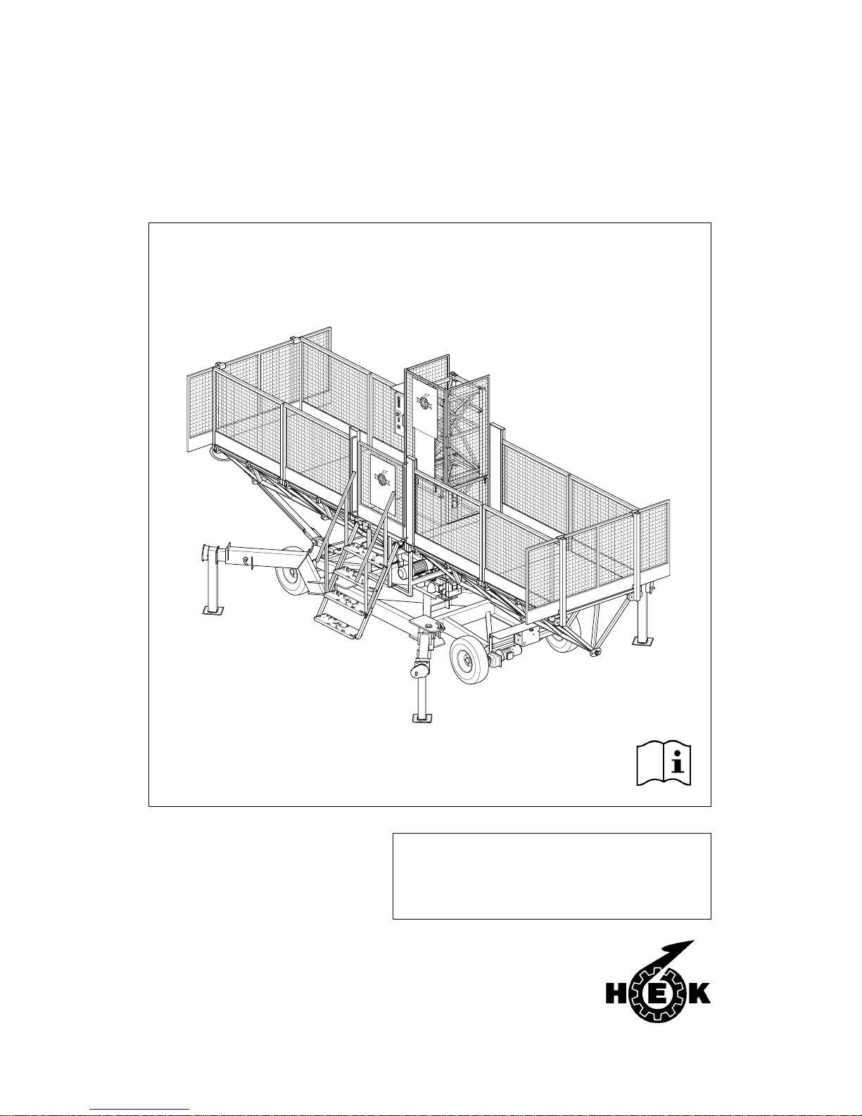
USER'S MANUAL
MSHF
MAST CLIMBING WORK PLATFORM
This manual is assigned to:
Page 2

II MSHF • 7295-026A
© 2000, HEK Manufacturing BV ., Middelbeers, The Netherlands
Nothing contained in this publication may be copied, and/or published by means of
printing, photocopying, microfilm or any other method without prior written permission from
HEK Manufacturing B.V .
Page 3

IIIMSHF • 7295-026A
HEK Manufacturing B.V.
Westelbeersedijk 18 P.O. box 2
5091 SM Middelbeers 5090 AA Middelbeers
The Netherlands The Netherlands
Tel : +31 13 51 48 653
Fax : +31 13 51 48 630
Page 4

IV MSHF • 7295-026A
Page 5
VMSHF • 7295-026A
FOREWORD
FOREWORD
The mast climbing work platform is
provided with a rack and pinion drive.
The mast climbing work platform can be
quickly moved and is easy to transport.
The mast climbing work platform can be
fitted with one or two masts and can be
freestanding or anchored.
The mast, which consists of separate
elements, can easily be adjusted in
height to match the height of the building
work. The mast is easy to assemble from
the platform.
Read this instruction manual carefully before using the
mast climbing work platform. Take all the safety
precautions as described in chapter 3 into account.
The platform can be adjusted to the
shape of the façade.
The MSHF mast climbing work platform
has a control system which makes it
possible to stop at any desired height.
Every care has been taken in the
construction of the mast climbing work
platform to ensure that all safety aspects
have been considered.
Depending on the application area, a
choice can be made from different
platform lengths, platform widths and
permissible loading.
This instruction manual describes only
the basic machine, in the standard form
supplied by HEK Manufacturing BV.
Page 6

VI MSHF • 7295-026A
CONTENTS
CONTENTS
FOREWORD V
CONTENTS VI
SURVEY OF ILLUSTRA TIONS VII
EC DECLARA TION OF CONFORMITY VIII
MEANING OF THE SYMBOLS USED IX
1. TECHNICAL DETAILS 1-1
1.1 General 1-1
1.2 Electrical installation 1- 5
1.3 Drive unit 1-5
1.4 Chassis 1-7
1.5 Ground frame 1-7
1.6 Platform construction 1- 8
1.6.1 Symmetrical platform construction 1- 8
1.7 Loading of the mast climbing
work platform 1-10
1.7.1 Outriggers chassis 1-10
1.7.2 Single mast machine 1- 11
1.7.3 Twin mast machine 1-12
1.8 Anchorforces 1-14
2. COMPONENT DESCRIPTION 2-1
2.1 General description 2- 1
3. SAFETY 3-1
3.1 General 3-1
3.2 Safety prior to use 3- 1
3.3 Safety in use 3-1
3.4 Safety after use 3- 3
3.5 Built-in and additional safety features 3-3
4. TRANSPORT 4-1
4.1 Repositioning on the building site 4- 2
4.2 Chassis drive unit 4- 3
4.3 Repositioning with a crane 4- 4
5. CONTROL COMPONENTS 5-1
5.1 Power supply socket for the drive unit 5- 1
5.2 Power supply socket for the chassis 5-1
5.3 Platform control box 5- 2
6. ASSEMBL Y AND ANCHORING 6-1
6.1 Preparation for assembly 6- 2
6.2 Ground support 6-3
6.3 Positioning the mast climbing
work platform 6- 4
6.3.1 Mast climbing work platform with
single mast on a chassis 6-5
6.3.2 Mast climbing work platform with
one mast on a ground frame 6- 6
6.3.3 Mast climbing work platform with
two masts on a chassis 6-8
6.3.4 Mast climbing work platform with
two masts on ground frames 6- 11
6.4 Assembly of the mast 6-14
6.5 Anchoring the mast 6-17
6.6 Adjusting the platform width 6-19
6.7 Setting the machine left or right 6-21
6.8 Checking and adjusting the
lower striker plates 6-22
6.9 Checking the autolevel switches 6-23
6.10 Adjusting the EMOS system 6-24
6.1 1 Lightning protection 6-24
7. OPERATION 7-1
7.1 General 7-1
7.2 Preparation 7-1
7.3 Testing 7-3
7.4 Brake test 7-3
7.5 Operation from the platform 7-4
7.6 Operation in an emergency situation 7- 4
7.7 Eccentric overload device 7- 6
8. DISASSEMBL Y AND TRANSPORT 8- 1
9. MAINTENANCE 9-1
9.1 General 9-1
9.2 Maintenance intervals 9- 1
9.3 Autolevel mechanism check 9-3
9.4 The motor brake 9 -3
9.4.1 Operation 9-4
9.4.2 Maintenance 9-5
10. MALFUNCTION ANAL YSIS 10-1
1 1. MACHINE DISPOSAL 11 -1
12. LIST OF KEYWORDS 12-1
APPENDICES 1
Page 7

VIIMSHF • 7295-026A
CONTENTS
SURVEY OF ILLUSTRATIONS
Fig.1 Dimensions X
Fig.1-1 Mast element 1-2
Fig.1-2 Platform element 1-2
Fig.1-3 Plug-in fence 1-2
Fig.1-4 End fence 1-2
Fig.1-5 Corner post 1-2
Fig.1-6 Drive unit 1-4
Fig.1-7 Chassis 1-6
Fig.1-8 Ground frame 1-6
Fig.1-9 Outrigger locking 1-10
Fig.1-10 Anchor forces 1-14
Fig.2-1 Basic set MSHF chassis/
ground frame 2-1
Fig.4-1 Transport MSHF 4-1
Fig.4-2 Locking pin outrigger chassis 4-2
Fig.4-3 Brake lever chassis 4-2
Fig.4-4 Switch box chassis 4-3
Fig.4-5 Control box chassis 4-3
Fig.5-1 Power supply socket drive unit 5-1
Fig.5-2 Power supply socket chassis 5-1
Fig.5-3 Control box 5-2
Fig.6-1 Position machine 6-1
Fig.6-2 Ground support chassis 6-3
Fig.6-3 Ground support ground frame 6-3
Fig.6-4 Distance to the facade 6-4
Fig.6-5 Locking pin outrigger chassis 6-5
Fig.6-6 Autolevel locking pin 6-5
Fig.6-7 Lower striker plate 6-5
Fig.6-8 Lower striker plate 6-6
Fig.6-9 Step 6-6
Fig.6-10 Fence 6-6
Fig.6-11 Gate safety switch 6-6
Fig.6-12 Step 6-7
Fig.6-13 Autolevel locking pin 6-7
Fig.6-14 Fence 6-7
Fig.6-15 Gate safety switch 6-7
Fig.6-16 Locking pin outrigger chassis 6-8
Fig.6-17 Autolevel locking pin 6-8
Fig.6-18 Lower striker plate 6-8
Fig.6-19 Step 6-9
Fig.6-20 Fence 6-9
Fig.6-21 Gate safety switch 6-10
Fig.6-22 Autolevel locking pin 6-10
Fig.6-23 Control cable dummy plug 6-10
Fig.6-24 Autolevel locking pin 6-11
Fig.6-25 Lower striker plate 6-11
Fig.6-26 Gate safety switch 6-12
Fig.6-27 Step 6-12
Fig.6-28 Fence 6-12
Fig.6-29 Autolevel locking pin 6-13
Fig.6-30 Control cable dummy plug 6-13
Fig.6-31 Power supply 6-14
Fig.6-32 Main switch 6-14
Fig.6-33 Control buttons 6-15
Fig.6-34 Proximity switch 6-15
Fig.6-35 Red top mast element 6-16
Fig.6-36 Mast cover 6-16
Fig.6-37 Anchoring 6-19
Fig.6-38 Outrigger platform extension 6-20
Fig.6-39 Anchor ramp 6-20
Fig.6-40 Machine setting left 6-21
Fig.6-41 machine setting right 6-21
Fig.6-42 switch left/right setting 6-21
Fig.6-43 Adjusting lower striker plate 6-22
Fig.6-44 Brake lever drive unit 6-23
Fig.6-45 Autolevel switches 6-23
Fig.6.46 Adjusting EMOS 6-24
Fig.6-47 Lightning protection 6-25
Fig.7-1 Main switch 7-2
Fig.7-2 Emergency push-button 7-2
Fig.7-3 Brake lever drive unit 7-3
Fig.7-4 Push-buttons control box 7-4
Fig.7-5 Drive unit brake release 7-5
Fig.7-6 Signal light 7-6
Fig.8-1 Drive unit brake release 8-1
Fig.8-2 Autolevel locking locking pin 8-2
Fig.8-3 Control cable dummy plug 8-2
Fig.8-4 Securing outrigger 8-2
Fig.8-5 Bundle platform elements 8-3
Fig.8-6 Locking pin outrigger 8-3
Fig.9-1 Drive unit brake release 9-3
Fig.9-2 Motorbrake 9-4
Fig.9-3 Motorbrake 9-5
Page 8
VIII MSHF • 7295-026A
EC DECLARATION OF CONFORMITY
EC declaration of conformity for machines
(pursuant to Annex IIa of the Machine Directives 89/392/EEC)
We, HEK Manufacturing bv
Westelbeersedijk 18
5091 SM Middelbeers
The Netherlands
hereby declare that, on the basis of its design and construction, the mast climbing work
platform named below and brought into circulation by us conform to the relevant basic
safety and health requirements contained in the EC Machine Directives.
Changes made to the machine without our consent invalidate this declaration.
This declaration applies to the mast climbing work platform:
HEK MSHF
In accordance with: EC Machine Directives 89/392/EG, Annex IV
EC number: 08/205/A 16-4912B, 1-7-1996
Certified by (‘Notified Body’): TÜV HANNOVER/SACHSEN ANHAL T E.V .
HANNOVER, GERMANY
Date/Manufacturer’s signature: Middelbeers, the Netherlands,
November 1st 1999
Signatory: P.M. Blom, deputy manager
Page 9

IXMSHF • 7295-026A
MEANING OF THE SYMBOLS USED
WARNING
Failing to (exactly) comply with
the working or operating
instructions may lead to serious
injury , fatal accident, severe
mechanical damage or
operating losses.
During use, no person may stand
under the machine.
Danger: High voltage.
Danger of falling objects.
SYMBOLS
Page 10
X MSHF • 7295-026A
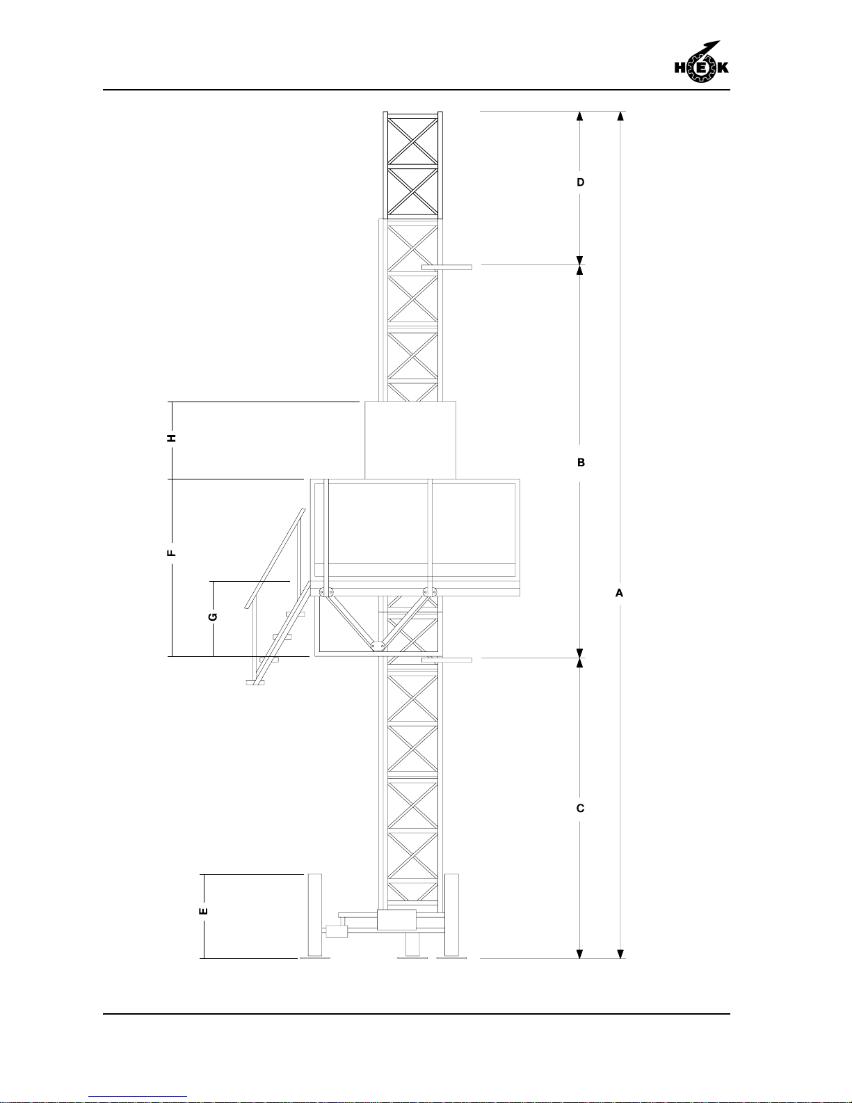
Fig.1 Dimensions
Page 11
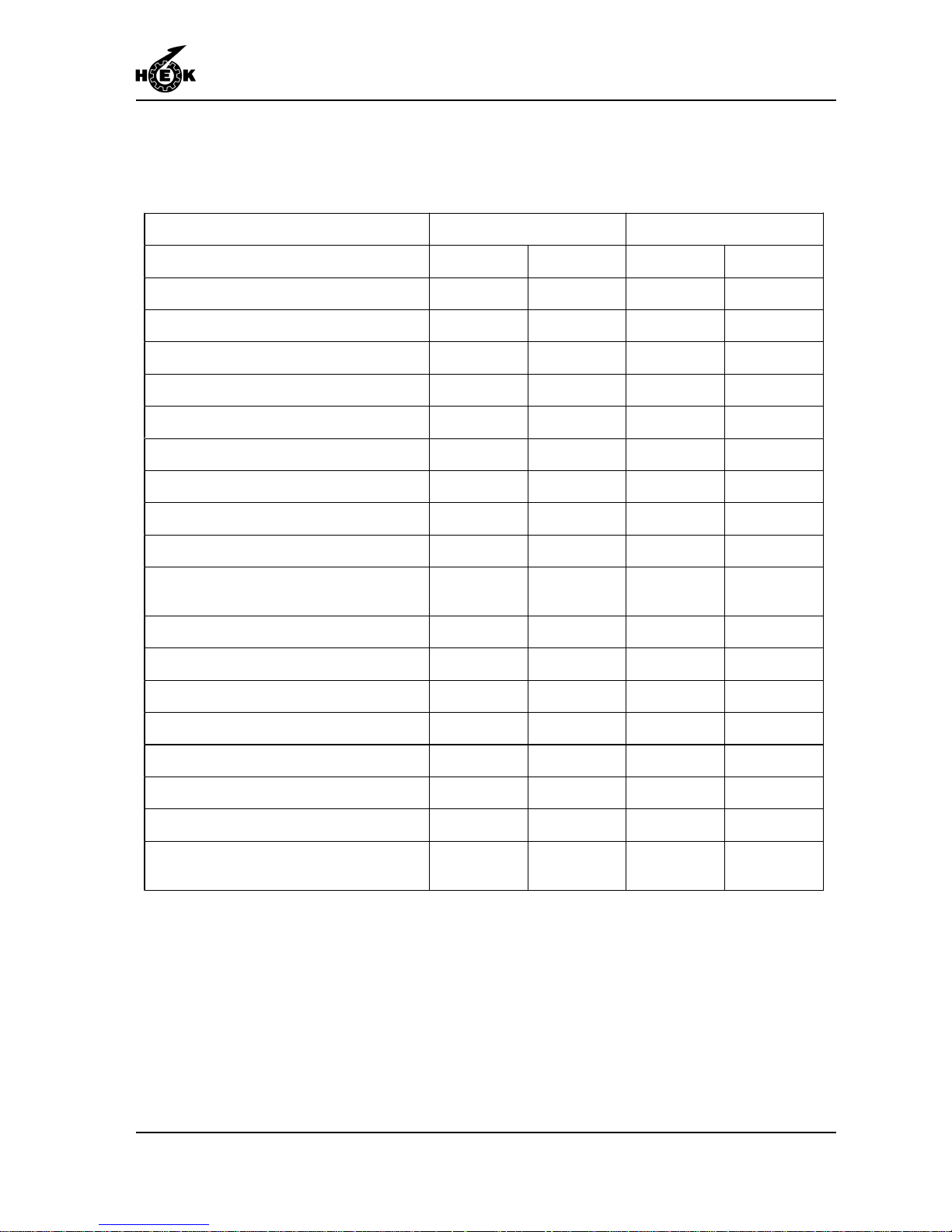
TECHNICAL DETAILS
1-1MSHF • 7295-026A
1. TECHNICAL DETAILS
1.1 General
Note:
The details are based on standard applications. In special situations, it may be possible
to deviate from these. This may only be done with the prior written approval of the
supplier.
For accessories and options see the accessory book.
Description MSHF 1 mast MSHF 2 masts
Platform length 2.9 - 10.3 m 9.5 - 33.8 ft 8.5 - 23.5 m 27.9 - 77.1 ft
Platform width 1.5 - 2.5 m 4.9 - 8.2 ft 1.5 - 2.5 m 4.9 - 8.2 ft
Distance between mast centres ---- ---- 7.3 - 13.3 m 14.1 - 43.6 ft
Distance between anchors (B) 13 - 15 m 42.7 - 49.2 ft 13 - 15 m 42.7 - 49.2 ft
Max. mastheight free-standing (A) 20 m 65.6 ft 20 m 65.6 ft
Max. mastheight anchored (A) 150 m 492 ft 150 m 492 ft
Max. mastheight above last anchor (D) 8 m 26.2 ft 8 m 26.2 ft
Mast type VRK700 VRK700 VRK700 VRK700
Max. number of persons 3366
Platform speed 7 m/min 23 ft/min 7 m/min 23 ft/min
Loading capacity see section
1.7
see section
1.7
see section
1.7
see section
1.7
Distance between cable guides 6 m 19.7 ft 6 m 19.7 ft
Height of first anchor for chassis (C) 15 m 49.2 ft 15 m 49.2 ft
Height of first anchor for ground frame (C) 3 m 9.8 ft 3 m 9.8 ft
Height of second anchor for ground frame 9 m 29.5 ft 9 m 29.5 ft
Height jacks chassis min - max (E) 0.67 - 0.97 m 2.2 - 3.0 ft 0.67 - 0.97 m 2.2 - 3.0 ft
Heig ht pl a tf o rm i n cl . f en ce 1 . 1 m / 3. 6 ft (F ) 1.95 m 6.4 ft 1.95 m 6.4 ft
Height platform to deck (G) 0.83 m 2.7 ft 0.83 m 2.7 ft
Height fence 1.1 m / 3.6 ft to upper side
mast cover (H)
1.36 m 4.5 ft 1.36 m 4.5 ft
Page 12
TECHNICAL DETAILS
1-2 MSHF • 7295-026A
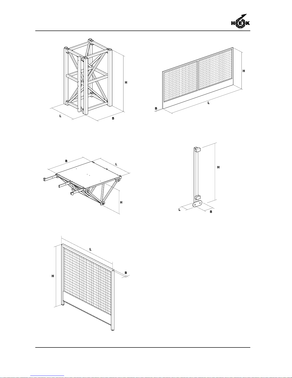
Fig.1-1 Mast element
Fig.1-4 End fence
Fig.1-5 Corner post
Fig.1-2 Platform element
Fig.1-3 Plug-in fence
Page 13
TECHNICAL DETAILS
1-3MSHF • 7295-026A
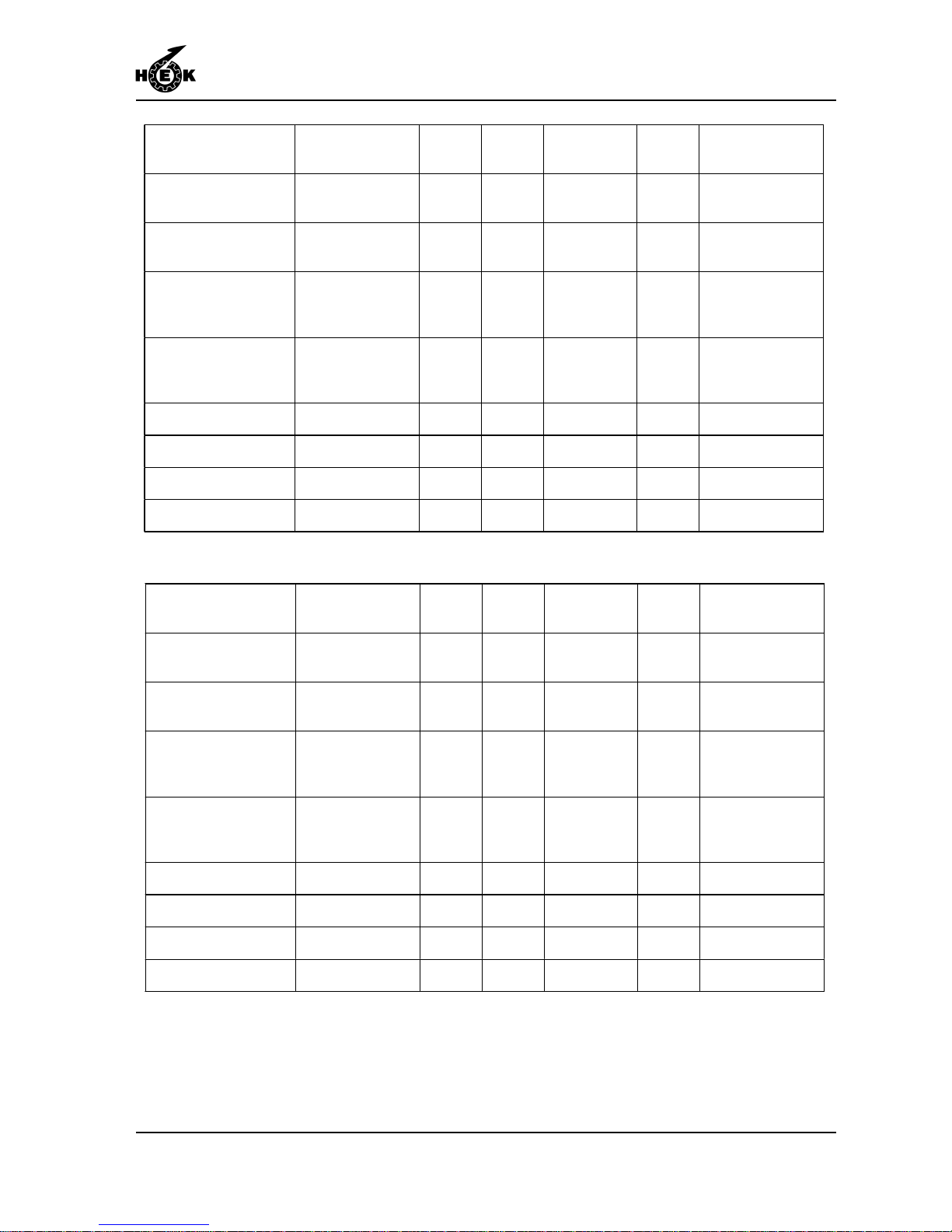
Part l x b x h [mm] weight
[kg]
No. of
bolts
bolt dim. &
quality
torque
[Nm]
other
Mast element 125 700x700x1256 80 4 M20 x 200
qual. 8.8
200 Module 8
Mast element 150 700x700x1508 103 4 M20 x 200
qual. 8.8
200 Module 8
Platform element 80 800x1580x800 90 6 M20 x 90
qual. 8.8
200 Max. platform
extension façade
side 1000 mm
Platform element 150 1500x1580x800 140 6 M20 x 90
qual. 8.8
200 Max. platform
extension façade
side 1000 mm
Plug-in fence 80 780x40x1120 12 --- --- --- --Plug-in fence 150 1480x40x1120 18 --- --- --- --End fence 2500x30x1120 30 --- --- --- --Corner post 170x60x1300 6,5 --- --- --- ---
Part l x b x h [in]
weight
[lb]
No. of
bolts
bolt dim. &
quality
torque
[lb ft]
other
Mast element 125 27.6x27.6x49.4 176 4
M20 x 7.9 in
qual. 8.8
150 Module 8
Mast element 150 27.6x27.6x59.4 227 4
M20 x 7.9 in
qual. 8.8
150 Module 8
Platform element 80 31.5x62.2x31.5 198 6
M20 x 3.5 in
qual. 8.8
150
Max. platform
extension façade
side 39.4 in.
Platform element 150 59.1x62.2x31.5 308 6
M20 x 3.5 in
qual. 8.8
150
Max platform
extension façade
side 39.4 in
Plug-in fence 80 30.7x1.6x44.1 26 --- --- --- --Plug-in fence 150 58.3x1.6x44.1 40 --- --- --- --End fence 98.4x1.2x44.1 66 --- --- --- --Corner post 6.7x2.4x51.2 14 --- --- --- ---
Page 14
TECHNICAL DETAILS
1-4 MSHF • 7295-026A
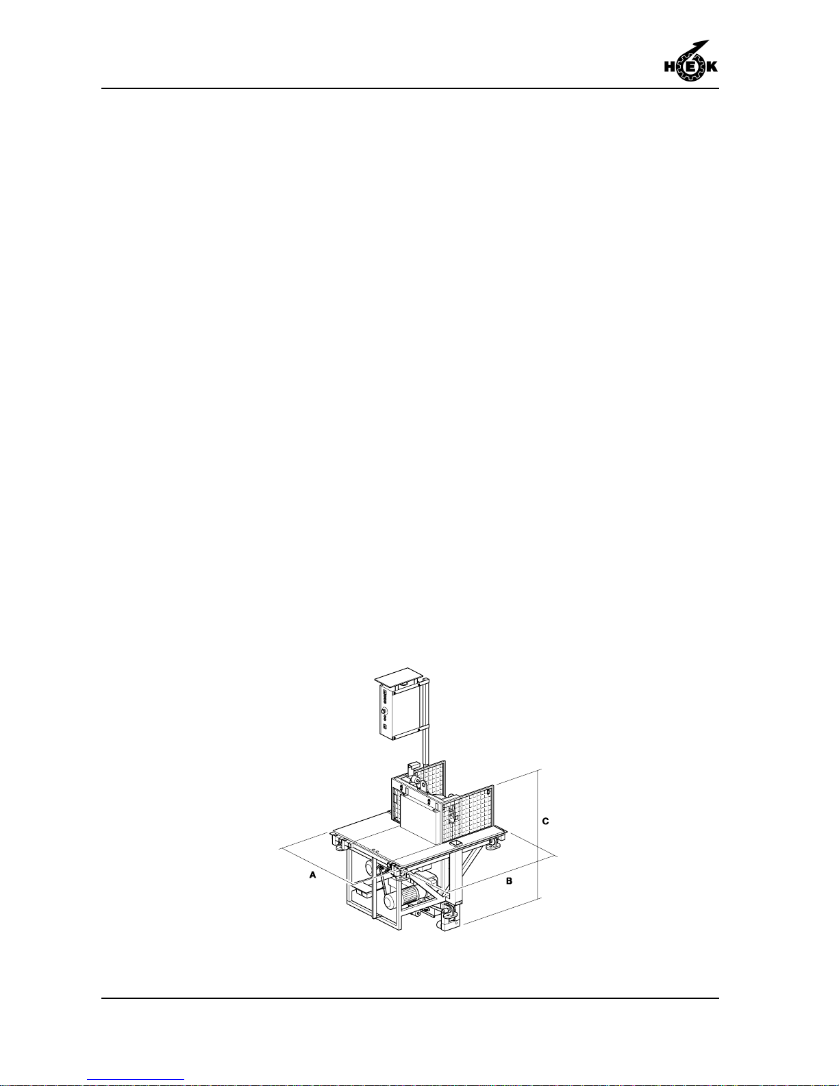
Fig.1-6 Drive unit
Page 15
TECHNICAL DETAILS
1-5MSHF • 7295-026A
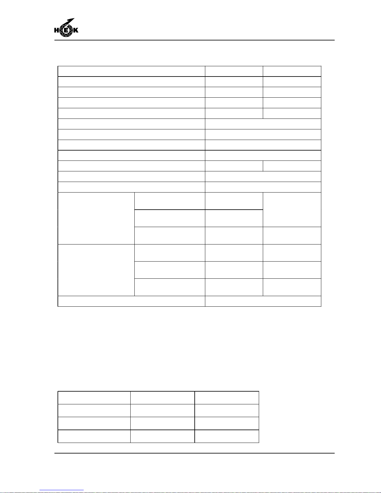
1.2 Electrical installation
1.3 Drive unit
MSHF 1 mast MSHF 2 masts
Number of motors 2 4
Rated power mast climbing work platform 2 x 2.1 kW 4 x 2.1 kW
Maximum starting current ± 80 A ± 160 A
Power consumption (based on S3-25%) 2 x 2.9 kVA 4 x 2.9 kVA
Supply voltage 200 - 240 V
Minimum supply voltage 180V
Phases 3 + Pe
Supply frequency 50 or 60 Hz
Fuse at building site (slow) 25 A 40 A
Control voltage 42 Vac
Control voltage frequency 50/60 Hz
up to 60 m / 197 ft 5 x 6 mm² /
5 x 0.0093 in
up to 100 m / 328 ft 5 x 10 mm² /
5 x 0.016 in
5 x 10 mm²
5 x 0.016 in
Power supply (to machine)
up to 150 m / 492 ft 5 x 16 mm² /
5 x 0.025 in
5 x 16 mm² /
5 x 0.025 in
5 x 6 mm², 0.64 kg/m
5 x 0.0093 in / 0.32 lb/ft
up to 70 m / 230 ft up to 40 m / 131 ft
5 x 10 mm², 1.11 kg/m
5 x 0.016 in / 0.43 lb/ft
up to 100 m / 328 ft up to 75 m / 246 ft
Machine cable / weight
5 x 16 mm², 1.80 kg/m
5 x 0.025 in / 0.74 lb/ft
up to 150 m / 492 ft up to 150 m / 492 ft
Single phase outlet 120 V / 16 A
Dimension A 1270 mm 50.1 in
Dimension B 1580 mm 62.2 in
Dimension C 1610 mm 63.4 in
Weight 950 kg 2090 lb
Page 16
TECHNICAL DETAILS
1-6 MSHF • 7295-026A
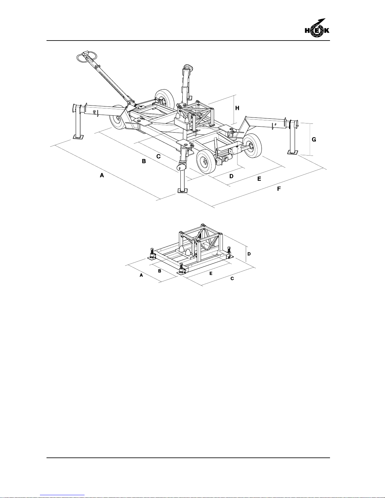
Fig.1-7 Chassis
Fig.1-8 Ground frame
Page 17
TECHNICAL DETAILS
1-7MSHF • 7295-026A
1.4 Chassis
1.5 Ground frame
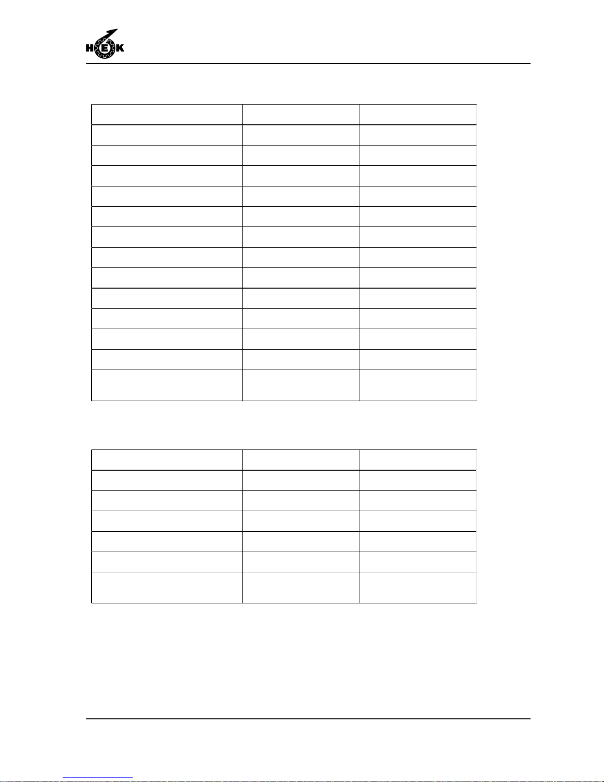
Dimension A 1200 mm 47.2 in
Dimension B 600 mm 23.3 in
Dimension C 1560 mm 61.4 in
Dimension D 500 - 600 mm 19.7 - 23.6 in
Dimension E 1100 mm 43.3 in
Weight 182 kg 400 lb
Height of the platfrom from the
ground
depending of lower striker
plate
depending of lower striker
plate
Dimension A 4520 - 6540 mm 175.9 - 257.5 in
Dimension B 4300 mm 167.3 in
Dimension C 2150 mm 83.7 in
Dimension D 1250 mm 48.6 in
Dimension E 1770 mm 69.7 in
Dimension F 1600 - 4590 mm 63.0 - 178.6 in
Dimension G 668 - 968 mm 26.0 - 37.7 in
Dimension H 775 - 848 mm 30.2 - 33.0 in
Weight 1750 kg 3850 lb
Number of motors 1 1
Rated power 0.75 kW 0.75 kW
Tyre pressure 5 bar 71.5 psi
Driving speed 2 km/h 1.25 mph
Height of the platform from the
ground
depending on lower striker
plate
depending on lower striker
plate
Page 18
TECHNICAL DETAILS
1-8 MSHF • 7295-026A
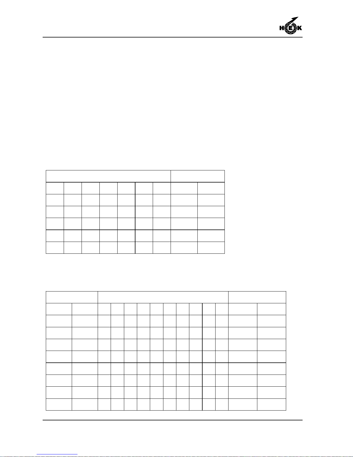
1.6 Platform construction
1.6.1Symmetrical platform
construction
Drive unit: 1.30 m / 4.26 ft = A
Element 80: 0.80 m / 2.62 ft = B
Element 150: 1.50 m / 4.92 ft = C
Twin mast machine
A-symmetrical configurations may be possible. This may only be done with prior written
approval of the supplier.
Single mast machine
Length platform
B A B 2.9 m 9.5 ft
C A C 4.3 m 14.1 ft
B C A C B 5.9 m 19.4 ft
C C A C C 7.3 m 24.0 ft
B C C A C C B 8.9 m 29.2 ft
C C C A C C C 10.3 m 33.8 ft
Mast distance* Centre panel between the masts Length platform
7.3 m 24.0 ft A C C C C A 8.5 m 27.9 ft
8.1 m 26.6 ft A C C C C B A 9.3 m 30.5 ft
8.8 m 28.9 ft A C C C C C A 10.0 m 32.8 ft
9.6 m 31.5 ft A C C C C C B A 10.8 m 35.4 ft
10.3 m 33.8 ft A C C C C C C A 11.5 m 37.7 ft
11.1 m 36.4 ft A C C C C C C B A 12.3 m 40.4 ft
11.8 m 38.7 ft A C C C C C C C A 13.0 m 42.7 ft
12.6 m 41.3 ft A C C C C C C C B A 13.8 m 45.3 ft
13.3 m 43.6 ft A C C C C C C C C A 14.5 m 47.6 ft
Page 19
TECHNICAL DETAILS
1-9MSHF • 7295-026A
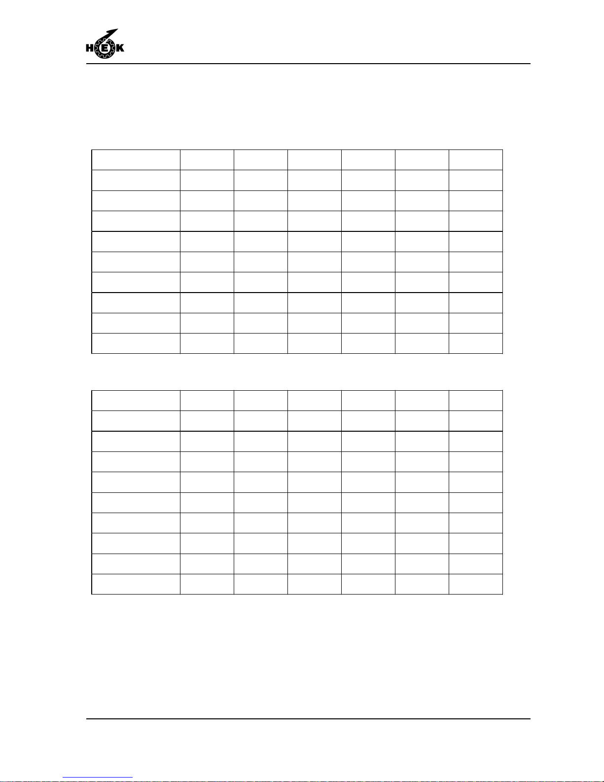
Side panels (2x) in case of a symmetrical installation.
With multiple elements, the element of 1.5 m / 4.92 in (C) must be attached on the side
of the mast.
* The mast distance and thus the platform length can be enlarged (10cm / 3.94 in),
by replacing one element 150 by two elements 80.
** These combinations are not allowed.
Mast distance* B C B + C C + C B + C + C C + C + C
24.0 ft 33.1 ft 37.7 ft 43.0 ft 47.2 ft ** **
26.6 ft 35.8 ft 40.4 ft 45.6 ft 50.2 ft ** **
28.9 ft 38.1 ft 42.7 ft 47.9 ft 52.8 ft 57.7 ft **
31.5 ft 40.7 ft 45.3 ft 50.5 ft 55.1 ft 60.4 ft 65.0 ft
33.8 ft 43.0 ft 47.2 ft 52.8 ft 57.4 ft 62.7 ft 67.3 ft
36.4 ft 45.6 ft 50.2 ft 55.4 ft 60.0 ft 65.3 ft 70.0 ft
38.7 ft 47.9 ft 52.5 ft 57.7 ft 62.3 ft 67.6 ft 72.5 ft
41.3 ft 50.5 ft 55.1 ft 60.4 ft 65.0 ft 70.2 ft 74.8 ft
43.6 ft 52.8 ft 57.4 ft 62.7 ft 67.3 ft 72.5 ft 77.1 ft
Mast distance * B C B + C C + C B + C + C C + C + C
7.3 m 10.1 m 11.5 m 13.1 m 14.4 m ** **
8.1 m 10.9 m 12.3 m 13.9 m 15.3 m ** **
8.8 m 11.6 m 13.0 m 14.6 m 16.1 m 17.6 m **
9.6 m 12.4 m 13.8 m 15.4 m 16.8 m 18.4 m 19.8 m
10.3 m 13.1 m 14.4 m 16.1 m 17.5 m 19.1 m 20.5 m
11.1 m 13.9 m 15.3 m 16.9 m 18.3 m 19.9 m 21.3 m
11.8 m 14.6 m 16.0 m 17.6 m 19.0 m 20.6 m 22.1 m
12.6 m 15.4 m 16.8 m 18.4 m 19.8 m 21.4 m 22.8 m
13.3 m 16.1 m 17.5 m 19.1 m 20.5 m 22.1 m 23.5 m
Page 20
TECHNICAL DETAILS
1-10 MSHF • 7295-026A
1.7 Loading of the mast climbing
work platform
1.7.1Outriggers chassis
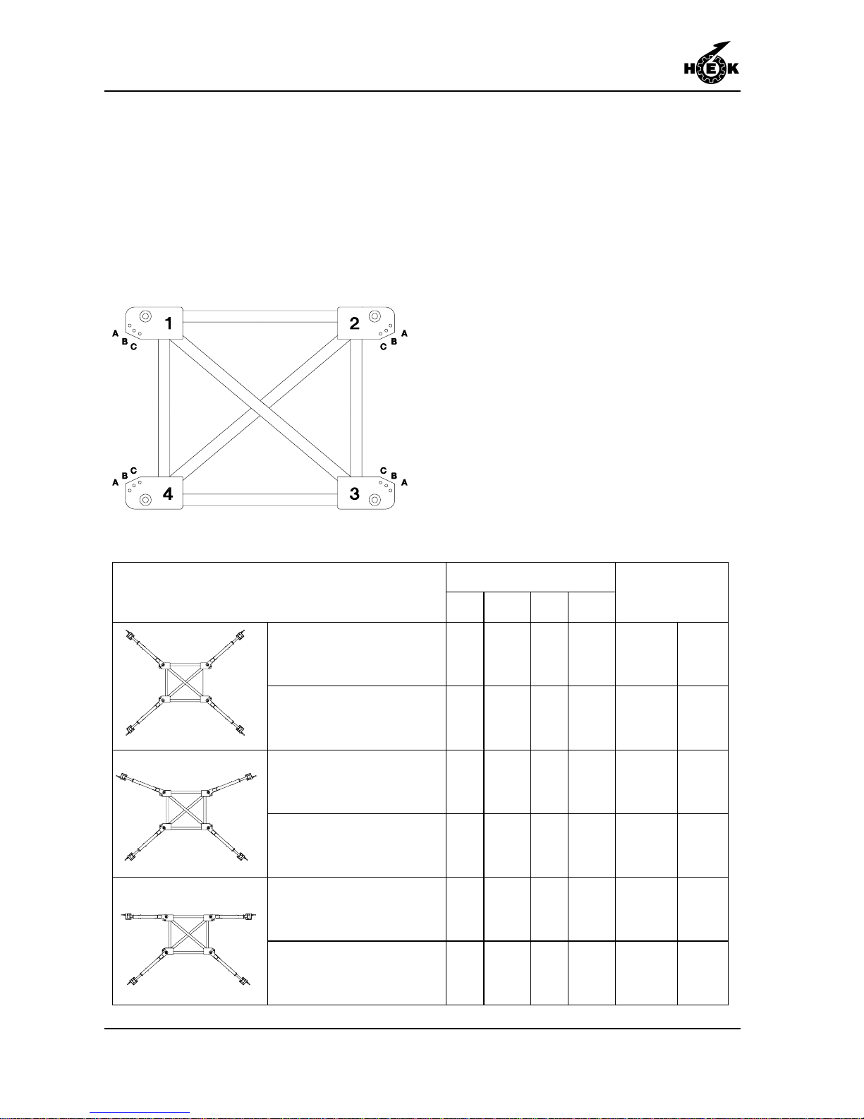
The outriggers of the chassis can be placed and locked in different positions. The
maximum free standing height of the mast climbing work platform is also depended on
the position of the outriggers.
Fig.1-9 Outrigger locking
Position of the locking pinPosition of the outriggers
1234
Maximum
freestanding
mast height
X -position front A A A A 20 m 65.6 ft
X -position back A A A A 20 m 65.6 ft
½K -position front A A B B 15 m 49.2 ft
½K -position back B B A A 15 m 49.2 ft
K -position front A A C C 7.5 m 24.6 ft
K -position back C C A A 7.5 m 24.6 ft
Page 21
TECHNICAL DETAILS
1-11MSHF • 7295-026A
1.7.2Single mast machine
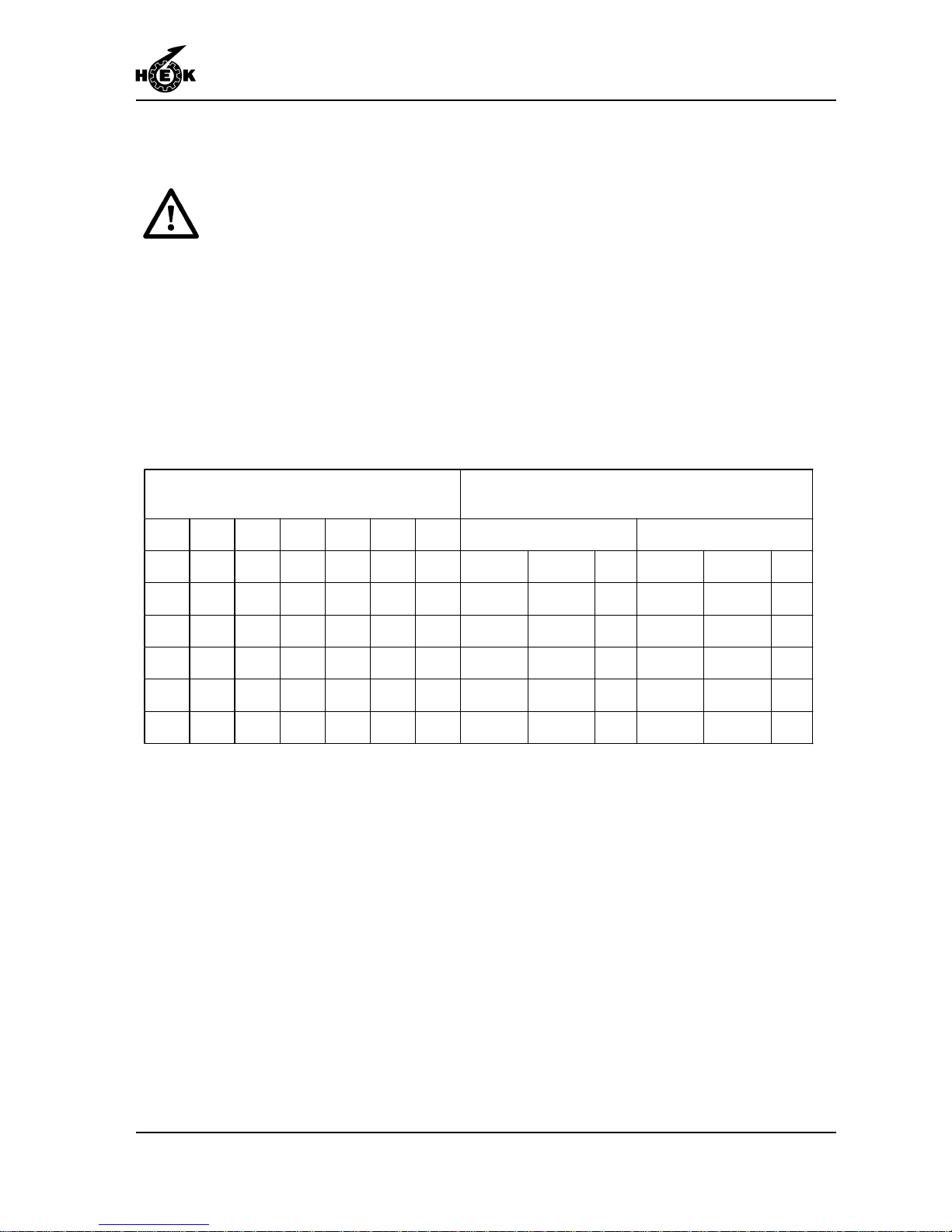
The payload must be equal
distributed on the platform.
Drive unit: 1.30 m / 4.26 ft = A
Element 80: 0.80 m / 2.62 ft = B
Element 150: 1.50 m / 4.92 ft = C
The P numbers in the diagram are the EMOS program numbers. For adjusting the EMOS
system see chapter 6.10.
Maximum payload single mast climbing work platform
* If the maximum height is limited to 17.5 m / 57.4 ft, the payload and the EMOS
setting of the anchored situation can be used.
Machine configuration
Maximum loading capacity depending of situation in
use
Anchored Free standing
B A B 2300 kg 5060 lb P22 2300 kg 5060 lb P22
C A C 2200 kg 4840 lb P22 2200 kg 4840 lb P22
B C A C B 2000 kg 4400 lb P22 2000 kg 4400 lb P22
C C A C C 1800 kg 3960 lb P22 1800 kg 3960 lb P22
B C C A C C B 1600 kg 3520 lb P22 1000 kg* 2200 lb* P15*
C C C A C C C 1500 kg 3300 lb P22 750 kg* 1650 lb* P13*
Page 22
TECHNICAL DETAILS
1-12 MSHF • 7295-026A
1.7.3Twin mast machine
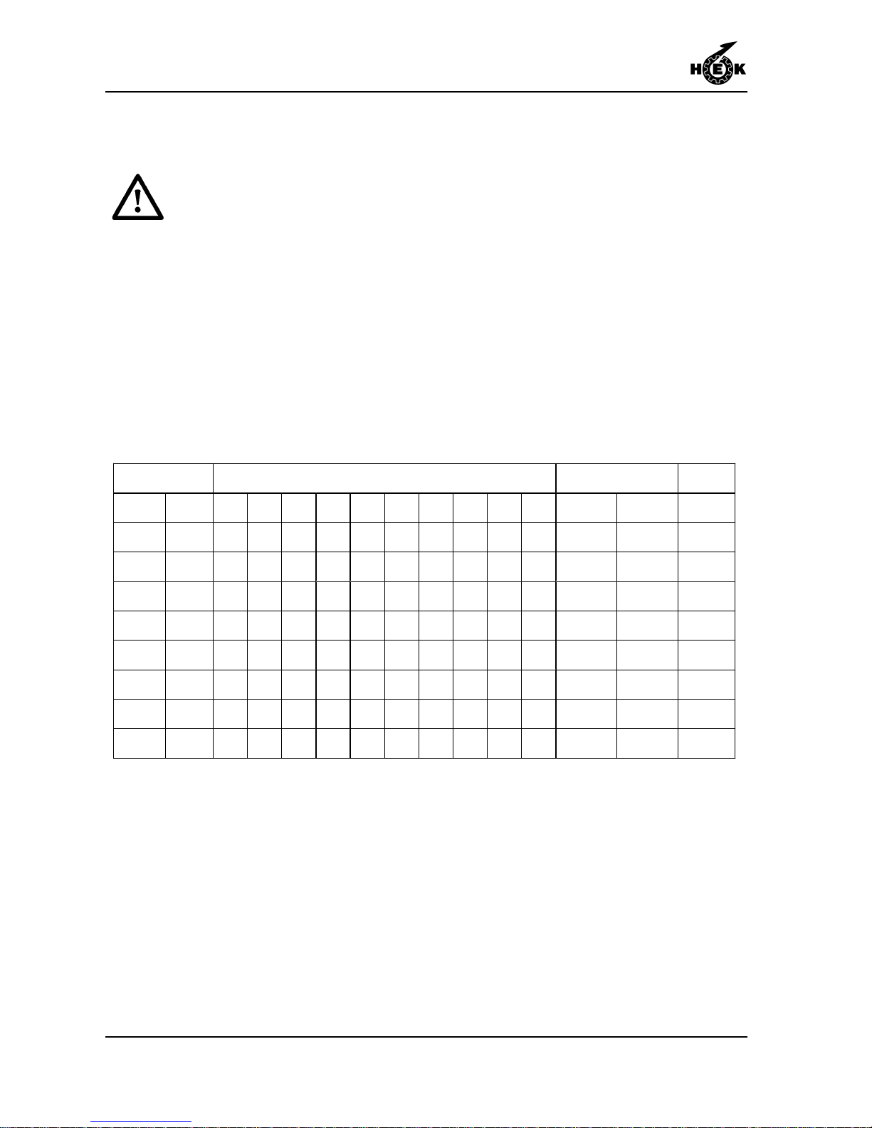
The payload must be equal
distributed on the platform.
Drive unit: 1.30 m / 4.26 ft = A
Element 80: 0.80 m / 2.62 ft = B
Element 150: 1.50 m / 4.92 ft = C
The P numbers in the diagrams are the EMOS program numbers. For adjusting the
EMOS system see chapter 6.10.
Maximum payload twin mast climbing work platform (free-standing or anchored).
Mast distance Centre panel between the masts Max. payload EMOS
7.3 m 24.0 ft A C C C C A 3500 kg 7700 lb P15
8.1 m 26.6 ft A C C C C B A 3500 kg 7700 lb P15
8.8 m 28.9 ft A C C C C C A 3500 kg 7700 lb P15
9.6 m 31.5 ft A C C C C C B A 3500 kg 7700 lb P16
10.3 m 33.8 ft A C C C C C C A 3500 kg 7700 lb P16
11.1 m 36.4 ft A C C C C C C B A 3000 kg 6600 lb P14
11.8 m 38.7 ft A C C C C C C C A 2700 kg 5940 lb P14
12.6 m 41.3 ft A C C C C C C C B A 2300 kg 5060 lb P12
13.3 m 43.6 ft A C C C C C C C C A 2000 kg 4400 lb P11
Page 23
TECHNICAL DETAILS
1-13MSHF • 7295-026A
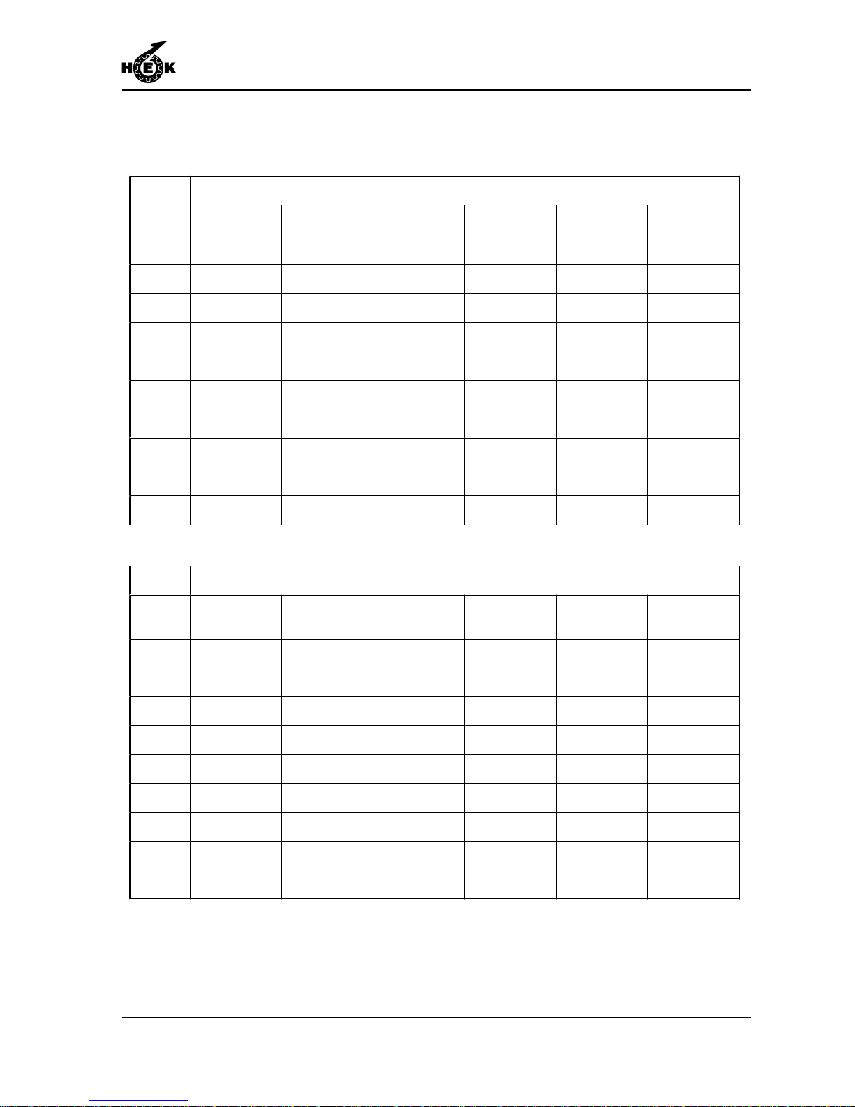
Maximum payload twin mast climbing work platform with side panels (free-standing or
anchored).
* Maximum free standing height in X-position 15 meter.
** These combinations are not allowed.
Platform elements on the side of the mast
Mast
distance
B C B + C C + C B + C + C * C + C + C *
24.0 ft 8800 lb / P19 8800 lb / P20 8360 lb / P20 7920 lb / P21 ** **
26.6 ft 8800 lb / P20 8580 lb / P20 8140 lb / P20 7700 lb / P20 ** **
28.9 ft 8800 lb / P21 8360 lb / P20 7920 lb / P20 7480 lb / P20 7040 lb / P20 **
31.5 ft 8580 lb / P21 8140 lb / P21 7700 lb / P21 7260 lb / P21 6820 lb / P21 6600 lb / P21
33.8 ft 8360 lb / P21 7920 lb / P21 7480 lb / P21 7260 lb / P21 6820 lb / P21 6380 lb / P21
36.4 ft 7700 lb / P20 7700 lb / P21 7260 lb / P21 7040 lb / P21 6600 lb / P21 6160 lb / P21
38.7 ft 6600 lb / P16 7260 lb / P19 7040 lb / P21 6820 lb / P21 6380 lb / P21 5940 lb / P20
41.3 ft 5720 lb / P15 6160 lb / P16 6600 lb / P19 6600 lb / P21 6160 lb / P21 5720 lb / P21
43.6 ft 4820 lb / P12 5280 lb / P15 5720 lb / P17 5940 lb / P19 5940 lb / P21 5500 lb / P20
Platform elements on the side of the mast
Mast
distance
[m]
B C B + C C + C B + C + C * C + C + C *
7.3 4000 kg / P19 4000 kg / P20 3800 kg / P20 3600 kg / P21 ** **
8.1 4000 kg / P20 3900 kg / P20 3700 kg / P20 3500 kg / P20 ** **
8.8 4000 kg / P21 3800 kg / P20 3600 kg / P20 3400 kg / P20 3200 kg / P20 **
9.6 3900 kg / P21 3700 kg / P21 3500 kg / P21 3300 kg / P21 3100 kg / P21 3000 kg / P21
10.3 3800 kg / P21 3600 kg / P21 3400 kg / P21 3300 kg / P21 3100 kg / P21 2900 kg / P21
11.1 3400 kg / P20 3500 kg / P21 3300 kg / P21 3200 kg / P21 3000 kg / P21 2800 kg / P21
11.8 3000 kg / P16 3300 kg / P19 3200 kg / P21 3100 kg / P21 2900 kg / P21 2700 kg / P20
12.6 2600 kg / P15 2800 kg / P16 3000 kg / P19 3000 kg / P21 2800 kg / P21 2600 kg / P21
13.3 2200 kg / P12 2400 kg / P15 2600 kg / P17 2700 kg / P19 2700 kg / P21 2500 kg / P20
Page 24
TECHNICAL DETAILS
1-14 MSHF • 7295-026A
1.8 Anchorforces
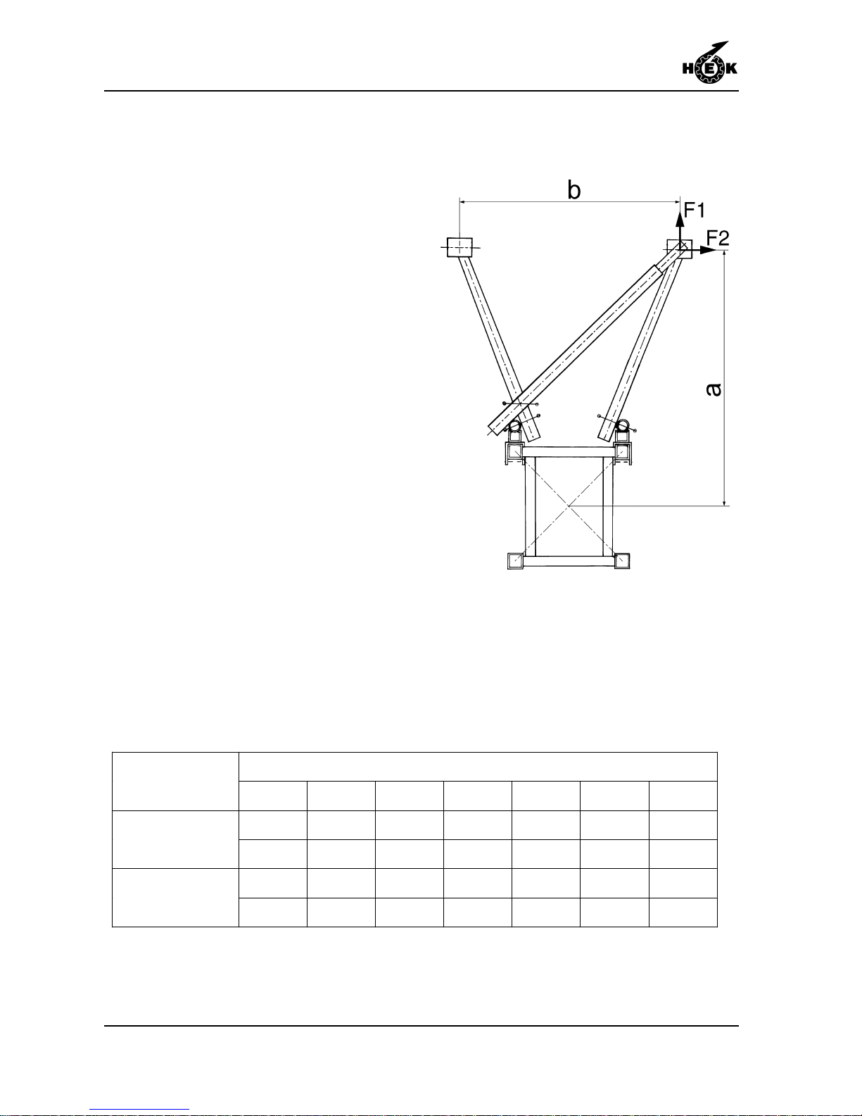
T orque scaf fold coupling: 50 Nm / 37 lb ft.
With the calculation of the anchor forces
show in the table the following demands
are considered:
- Anchor distance: 13-15 m /
42.6 - 49.2 ft
- Maximum mastheight above last anchor:
0.4 x anchor distance
- Loading during assembling:
Single: max. 750 kg / 1650 lb
+ 2 persons
Twin: max. 1500 kg / 3300 lb
+ 4 persons
- Maximum, windspeed during
assembling: 6 Beaufort (12,5 m/sec).
(41 ft/sec)
- Distance a (mast centre to facade):
0.9 -1.63 m / 35.4 - 64.2 in
- Distance b (between the anchor points
on the facade): min. 0.7 m / 27.6 in
- Ratio a/b: 0.8 - 2.0
The anchorforces of the MSHF up to 100 meters are given in the undermentioned table.
Above 100 meters the anchor forces will be 20 % higher than the anchor forces in the
given table.
Fig.1-10 Anchor forces
Ratio a/b
0.8 1.0 1.2 1.4 1.6 1.8 2.0
5.9 kN 7.0 kN 8.3 kN 9.5 kN 10.7 kN 11.9 kN 13.0 kN
Anchorforce F1
1327 lbf 1574 lbf 1865 lbf 2136 lbf 2406 lbf 2676 lbf 2923 lbf
4.2 kN 4.7 kN 5.3 kN 5.7 kN 5.9 kN 5.6 kN 6.0 kN
Anchorforce F2
945 lbf 1057 lbf 1192 lbf 1281 lbf 1327 lbf 1259 lbf 1349 lbf
Page 25
COMPONENTS
2-1MSHF • 7295-026A
2. COMPONENT DESCRIPTION
2.1 General description
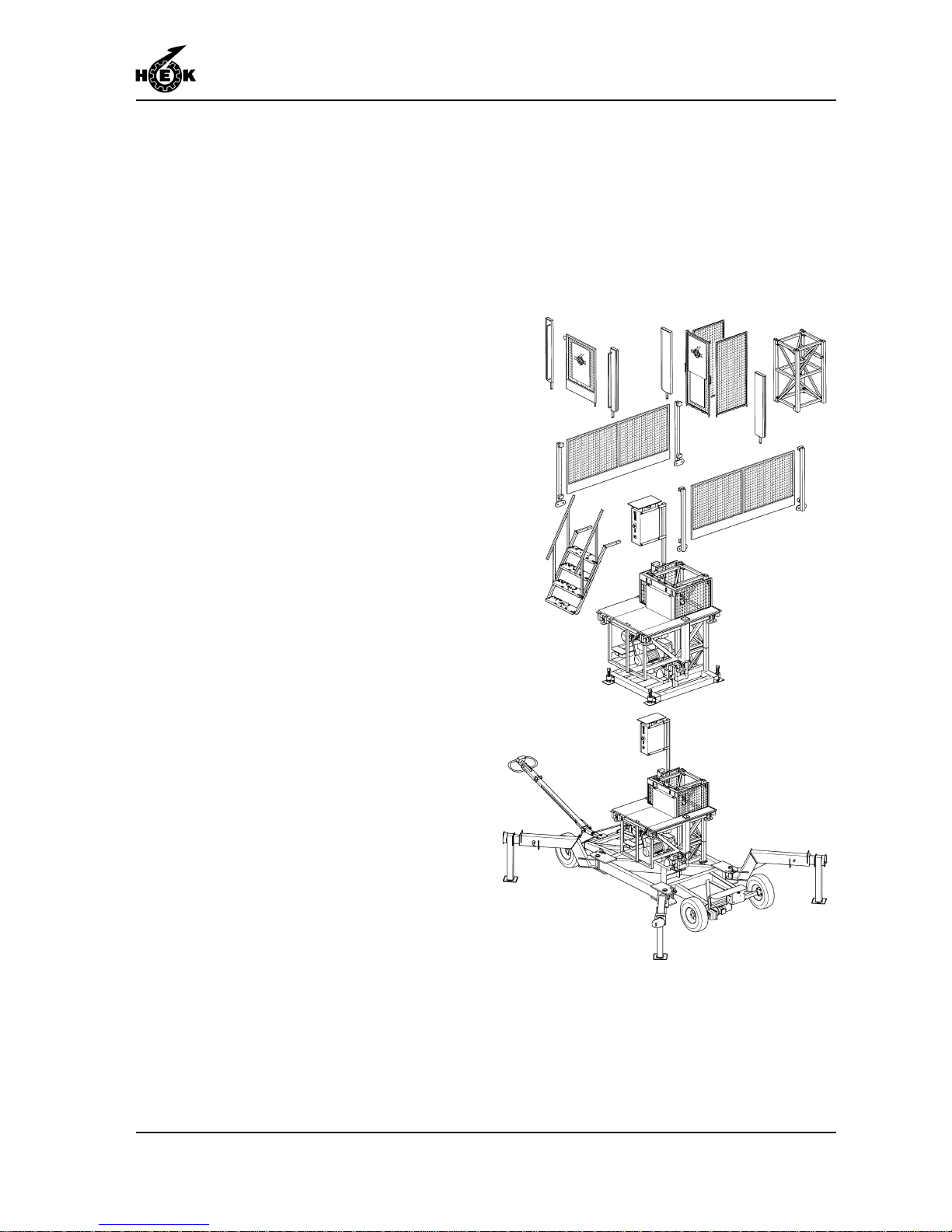
The basic set of the mast climbing work
platform with rack and pinion drive consists
of the following 5 main parts:
* drive unit
* mast
* platform elements and fences
* chassis or ground frame
* control system
The drive unit moves along the mast with
the aid of Nylontron rollers.
The motors are fitted with centrifugal
brakes which retard the platform if the
speed of descent is exceeded.
The drive unit, operated by 2 electric
motors, is moved along the mast by means
of a single pinion on each motor. For a
mast climbing work platform with two
masts, the motors are automatically
controlled to ensure parallel operation.
Much consideration has been given to
simple and safe assembly and
disassembly.
A crane on the platform (option) ensures
that the mast elements can be positioned
quickly and safely .
The platform can be adjusted to suit the
required working situation with the use of
separate platform elements. The width of
the platform can be adjusted by means of
outriggers.
Fig.2-1 Basic set MSHF chassis/ground frame
Page 26

COMPONENTS
2-2 MSHF • 7295-026A
All electrical connections, which must be
disconnected for transport purposes, can
be made by means of connectors.
The electrical installation is divided over
three boxes:
- The control box on the platform.
- The connection box on the chassis (only
when a chassis is used)
- The control box on the tow bar (only
when a chassis is used)
The simple construction ensures that only a
minimum of maintenance is required.
The mast elements, the chassis, the drive
unit, the cable guides and various other
components are protected from corrosion
by an appropriate surface treatment.
Page 27
SAFETY
3-1MSHF • 7295-026A
3. SAFETY
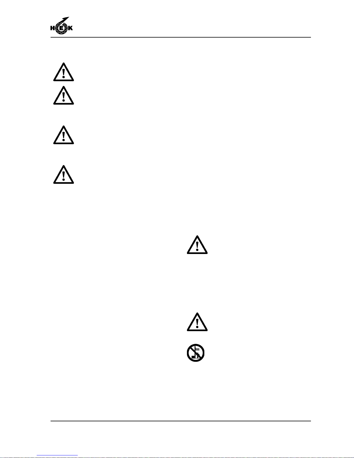
No changes or modifications
may be made to the machine.
The ground surface must be
sufficiently stable to support the
weight of the machine and the
mast.
The mast must AL WA YS be
anchored in accordance with the
instructions
If during assembly and
disassembly , the fences do not
provide sufficient protection,
suitable safety harness must be
used at heights above 2 metres.
3.1 General
The machine is constructed to be safe,
both during assembly and in use. The
machine is thus provided with the following
built-in and additional safety features:
- The motor brake works automatically if
the supply voltage fails.
- If the TOP limit switch fails to operate,
so that the mast climbing work platform
continues to rise, an additional
emergency TOP limit switch is
operated.
- If the LOWER limit switch fails to
operate, so that the mast climbing work
platform continues to descend, an
additional emergency LOWER limit
switch is operated.
- If the TOP limit switch fails and the red
topmast is not mounted, so that the
mast climbing work platform continuous
to rise, the drive unit will rest on the
safety hooks.
- If the pinion runs out the rack the EMOS
system will stop the drive unit by means
of differential current measurement.
3.2 Safety prior to use
- The chassis or ground frame must be
effectively supported.
- The working area around the machine
must be free from obstacles.
- The machine must be securely
anchored at the specified intervals.
3.3 Safety in use
In winds of strengths above
6 Beaufort (12.5 m/s) (41.1 ft/s)
by a freestanding machine or
7 Beaufort (15.7 m/s) (51.5 ft/s)
by an anchored machine, the
machine must not be used and
the platform must be set in the
lowest position.
There must be no obstructions in
the path of the machine.
During use, no person should
stand under the machine.
Page 28
SAFETY
3-2 MSHF • 7295-026A
Material must never extend
beyond the outer limits of the
platform. Items which may roll
must be properly secured.
Materials must never be stacked
against the fencing.
If work must be carried on close
to high voltage cables, a
minimum safety distance of
15 m / 50 ft must be maintained.
When materials and/or tools with
a large surface area will be used
contact your supplier in
connection with wind sensitivity .
- If the machine is to be used during the
hours of darkness, the area must be
adequately lit, so that the user has a
good view in all conditions.
- In order to ensure that no person
unintentionally walks under the platform,
the mast climbing work platform must be
surrounded with suitable fencing.
- The machine may only be used for the
purpose for which it was designed, that
is, the vertical transportation of persons
and materials with a maximum weight
within the design limits of the particular
construction.
- Loads (materials, persons, etc.) must
be distributed in accordance with the
loading diagram.
- Operations on the mast climbing work
platform may only be carried out by
persons with adequate knowledge and
qualifications to do so.
- Inspection and maintenance must be
carried out as given in this instruction
manual.
- During assembly and maintenance, the
mast climbing work platform may not be
used for other purposes.
- Keep hatches in the base of the
platform clear. From the platform it must
be possible to get, to the emergency
descent controls via the hatches.
- The competence and sense of
responsibility of the operator or
engineer are essential to the efficient
use of the platform.
- Local safety laws and regulations must
always be followed.
- T echnical personnel must be in a
position to deal with any difficulty
encountered in every possible situation
during assembly and disassembly . The
operating personnel must be familiar
with those situations which can occur
during use.
- If operating or technical personnel report
errors or dangers or are not aware of
the safety regulations, the owner or the
person responsible must be informed
immediately.
- For machines with two masts, there
must always be two persons present on
the platform during use. This in case the
need to make an emergency descent.
- The working area must be kept free
from obstacles (building materials, dirt,
snow, etc.).
- Fences must never removed during
normal use.
- The platform must only be entered and/
or loaded when it is in its lowest
position. The same rule applies to
leaving the platform.
- When electrical storms are expected,
work on the platform must be stopped in
time to avoid the danger of lightening
strikes. The power supply must be
switched off and the connector
withdrawn from the supply socket.
Page 29

SAFETY
3-3MSHF • 7295-026A
- Platform extensions on telescopic
supports may only be used to carry
personnel. Such personnel may only
stand on these extensions when the
machine is stationary .
- If erecting two adjacent platforms there
must be a clear gap between the ends
of the platforms of at least 0.5 meter /
19.7 inch.
3.4 Safety after use
- Transport on public roads must only be
done with a truck intended for the
purpose.
- The platform must be placed in the
lowest position and the main switch
must be secured.
3.5 Built-in and additional safety
features
The MSHF mast climbing work platform is
provided with the following in-built and
additional safety features:
- Phase control relay in the control box.
- "Emergency stop" push button on every
control box.
- Electrical access protection.
- Hooks on the drive unit. The platform
remains secured on these should all the
limit switches fail and should the red
mast top section also be missing.
- Autolevel for machines with two masts.
Locks the platform if one side drops
more than the other during an
emergency descent.
- In the event of a power failure the motor
brakes are operated automatically to
prevent the platform descending
unexpectedly .
- Centrifugal brakes ensure a controlled
descent in the event of an emergency .
- The single mast construction has an
eccentric overload safety device. This
locks the platform if the platform is
overloaded on one side.
- The Emos system locks the platform if
one of the motors fails.
- In the event of a power failure it is
possible for the platform to make an
emergency descent by manually
releasing the motor brakes.
- Audio Visual Warning. During descent
of the platform, a buzzer will sound and
a light will flash underneath the platform.
- The mast climbing work platform can
only be moved on the chassis when the
platform is in the lowest position.
Page 30

SAFETY
3-4 MSHF • 7295-026A
Page 31
TRANSPORT
4-1
MSHF • 7295-026A
4. TRANSPORT
Transportation on the chassis
over the public roads is not
permitted.
The national valid traffic
regulations must be observed.
Because of its limited dimensions, the
basic implementation of the machine can
be transported with a normal lorry . Ensure
that, during transport, all securing devices
are properly fitted and that the machine is
lowered onto the buffers.
Disassemble the machine before
transporting it as described in chapter 8.
For the transport dimensions, see
chapter 1.
For transport, all fences, steps and mast
protection must be removed.
For transportation, secure the machine
carefully onto the loading platform of the
transport vehicle.
The machine can be loaded and unloaded
from the transport vehicle using a crane
mounted on the vehicle, a crane on the
building site or a fork-lift truck. See figure
4-1 for loading and unloading points.
Set the machine down carefully to avoid
damage.
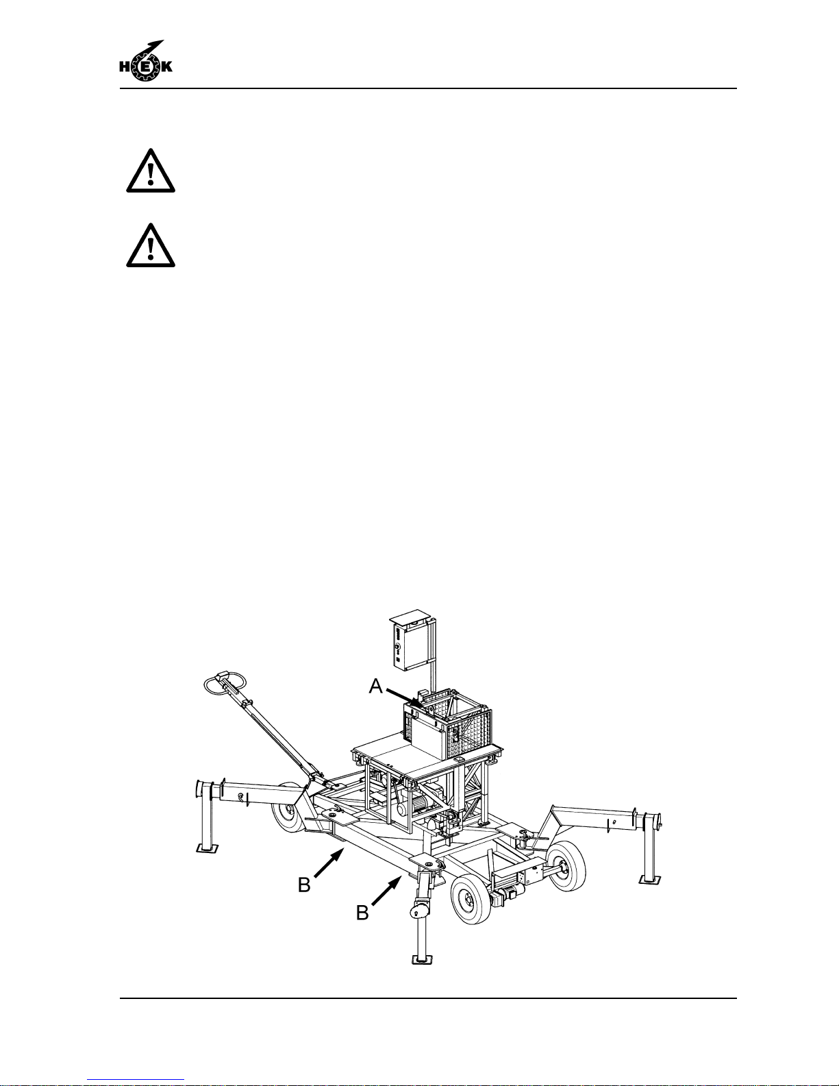
See figure 4-1
A Lifting point, for drive unit only!
B Support points for the fork of a fork-lift
truck.
Fig.4-1 Transport MSHF
Page 32
TRANSPORT
4-2 MSHF • 7295-026A
4.1 Repositioning on the building site
Ensure that trees, power cables
etc., cannot be touched.
During movement there may be
no load on the platform.
Once on the building site, the mast
climbing work platform can be moved in
the lowest position on its chassis.
On a hard flat horizontal surface and when
there is no wind, the mast may have a
maximum height of 20 m / 65.6 ft during
repositioning. The platform must be on the
buffers. The legs must be set out in an X
position and secured. The jack must be
screwed out until they just are clear the
ground.
When the circumstances are unfavourable
than the above mentioned circumstances,
contact your supplier.
A machine with two masts may only be
repositioned on its chassis if no curves
must be negotiated. If a curve must be
followed, the machine must first be split
into two single-mast machines. T ake the
maximum platform length of a single mast
machine into account.
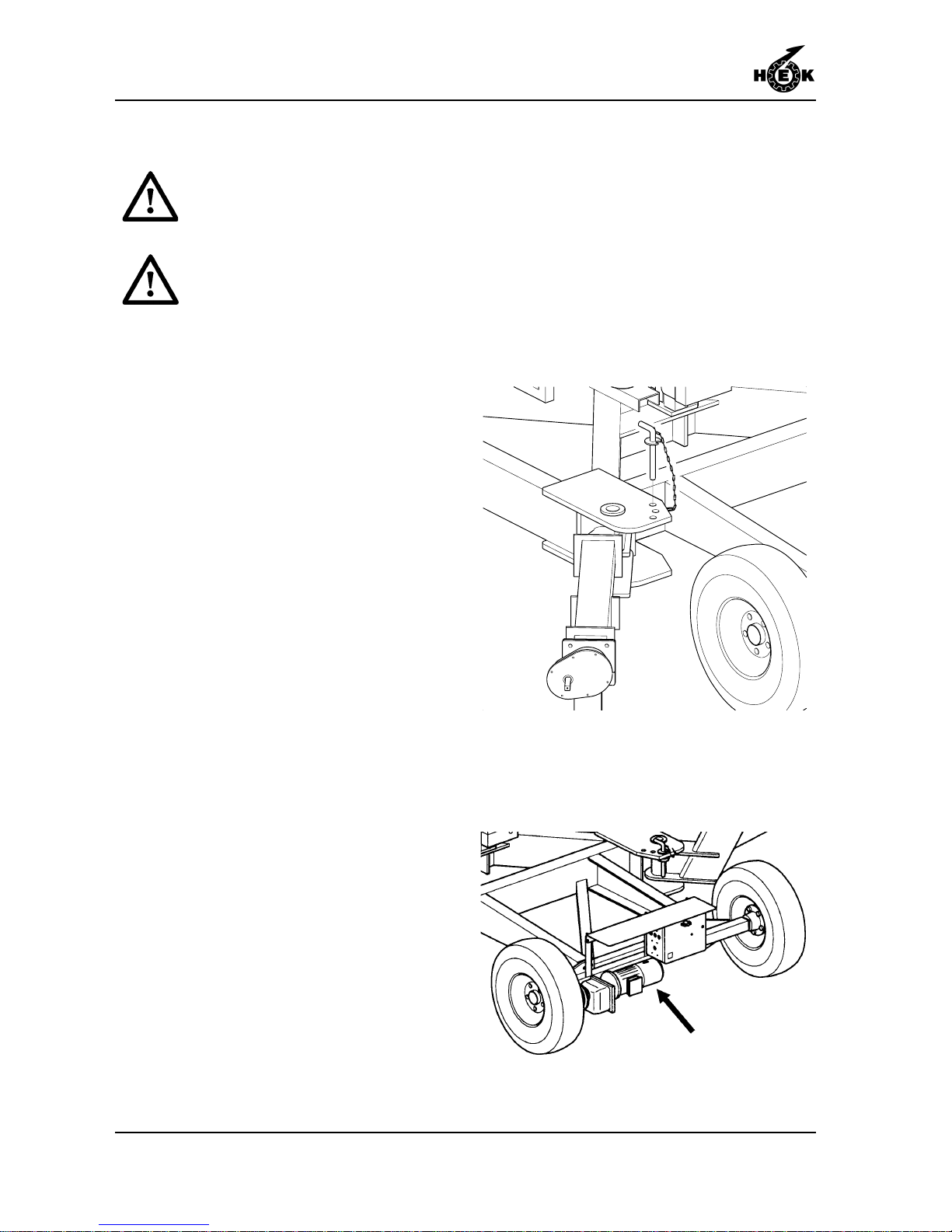
If there is no electrical power supply
available, the chassis can be moved by
hand or behind a vehicle. The hand brake
lever on the chassis motor must then be
used.
The maximum speed at which the chassis
may be towed behind a vehicle is 30 m/
min / 98.4 ft/min. Exceeding this speed can
cause serious damage to the motor.
Fig.4-2 Locking pin outrigger chassis
Fig.4-3 Brake lever chassis
Page 33
TRANSPORT
4-3
MSHF • 7295-026A
4.2 Chassis drive unit
Moving the machine on its
chassis over public roads is not
permitted.
During movement there may be
no load on the platform.
1. Place the platform in the lowest
position.
2. Check that the tow bar is secured.
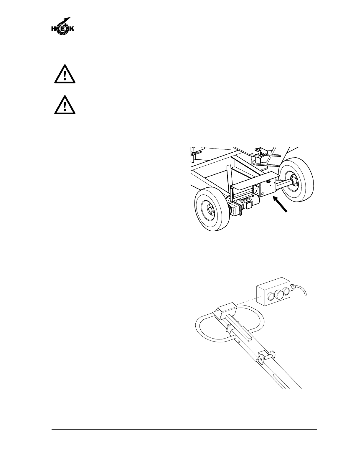
3. Insert the connector from the platform
in the socket on the switch box of the
chassis.
4. Connect the control cable from the
tow bar to the chassis.
5. The chassis can be repositioned by
pushing the knob (arrow) of the
required direction. The control
voltage can always be switched off by
pushing the emergency push-button.
After the chassis has been repositioned,
the red push-button must be pressed and
the connectors for the power supply and
controls withdrawn.
Fig.4-4 Switch box chassis
Fig.4-5 Control box chassis
Page 34

TRANSPORT
4-4 MSHF • 7295-026A
No. of drive units x 950 kg / 2090 lb =
No. of chassis x 1750 kg / 3850 lb =
No. of ground frames x 182 kg / 400 lb =
No. of platform elements 80 x 90 kg / 198 lb =
No. of platform elements 150 x 140 kg / 308 lb =
No. of mast elements 125 x 80 kg / 176 lb =
No. of mast elements 150 x 103 kg / 227 lb =
No. of plug-in fences 80 x 12 kg / 26 lb =
No. of plug-in fences 150 x 18 kg / 40 lb =
No. of head fences x 30 kg / 66 lb =
No. of corner posts x 6,5 kg / 14 lb =
Total transport weight = kg / lb
+
4.3 Repositioning with a crane
During movement there may be
no load on the platform.
At the building site the mast climbing
work platform can be repositioned with a
crane under the following circumstances.
A maximum of 9 mast elements may be
mounted on the chassis or the ground
frame. The eye hook of the crane can be
attached to the mast with lifting slings.
The total transport weight can be
calculated on the undermentioned way.
Page 35
CONTROL COMPONENTS
5-1MSHF • 7295-026A
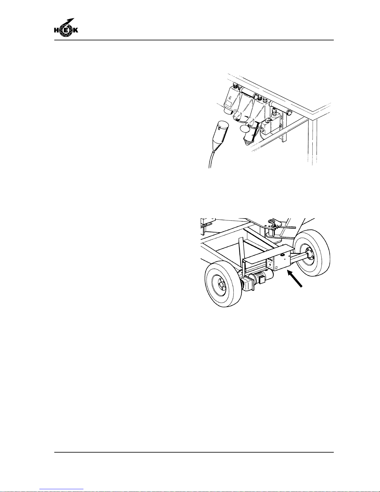
5. CONTROL COMPONENTS
5.1 Power supply socket for the drive
unit
The power supply cable for the electrical
supply between the building site
connection and the mast climbing work
platform must be connected to the socket.
See chapter 1 for the cable specifications.
5.2 Power supply socket for the
chassis
The power supply cable for the electrical
supply between the building site
connection and the chassis must be
connected to the socket.
Fig.5-1 Power supply socket drive unit
Fig.5-2 Power supply socket chassis
Page 36
CONTROL COMPONENTS
5-2 MSHF • 7295-026A
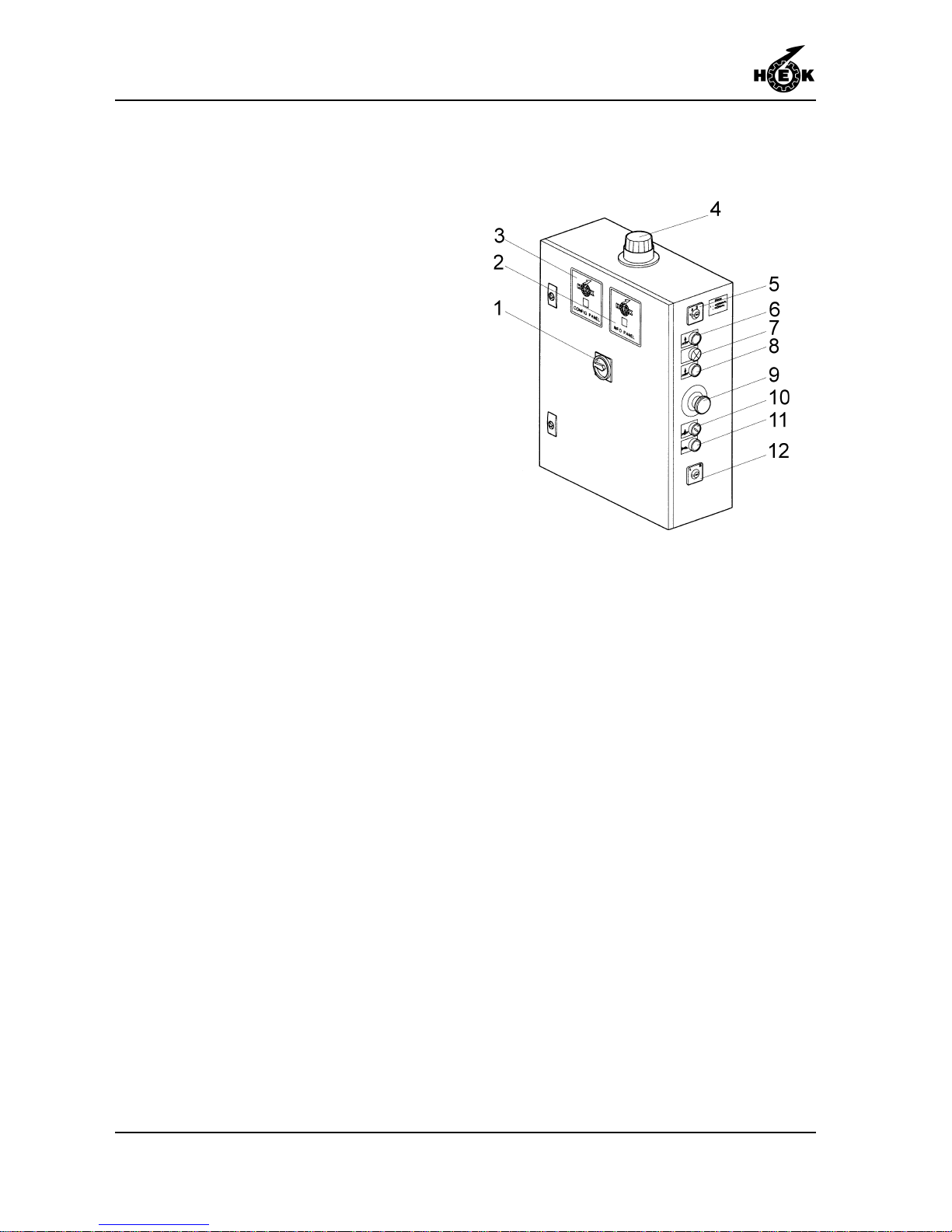
5.3 Platform control box
The door of the control box is secured with
two quick-release fastener .
The control box is provided with the
following push buttons:
1. Main switch.
2. Info panel.
3. Config panel.
4. Signal light.
5. Adjustment switch EMOS.
6. Push button UP .
7. Blue control light.
8. Push button DOWN.
9. Emergency push-button.
10. Keyswitch buffer .
11. Horn.
12. Keyswitch adjustment left/right.
When the Emergency push-button is
pressed it is locked in the depressed
position. It can be unlocked by rotating it.
The main switch can be secured with a
padlock to prevent unauthorized use of the
platform.
The following components are mounted in
the control box:
-the main switch
-the safety relay
-the control relay
-the transformer
-the automatic fuses
Fig.5-3 Control box
Page 37

ASSEMBLY AND ANCHORING
6-1MSHF • 7295-026A
6. ASSEMBLY AND ANCHORING
Definition left and right in relation to positioning:
Left-hand: Viewed from the step side, the machine is fitted to the left-hand side.
Right-hand: Viewed from the step side, the machine is fitted to the right-hand side.
Fig.6-1 Position machine
If assembly work must be interrupted, this must be done in such a way that, when the work
is restarted it is clear what stage had been reached when work was stopped. For this
reason always complete a part of the assembly , for example, assemble collect or secure all
the components for a connection, complete a ground support or completely assemble an
anchor before stopping work.
While the mast is being erected, no more than two persons with a single mast machine or
four persons with a twin mast machine, may be on the platform, so that no more than 75%
of the lifting capacity is used.
The assembly must always be followed by a test run, as described in section 7.3. Until the
test has been performed, the platform may not be used for any purpose other than
transporting its own mast elements and anchoring components.
The loading of the mast climbing work platform must be planned so that when, in the
assembly situation, the maximum height of the mast above the last anchor is reached (the
maximum distance between anchors), the material load on the platform is a minimum.
Page 38
ASSEMBLY AND ANCHORING
6-2 MSHF • 7295-026A
6.1 Preparation for assembly
Ensure that the site where the
mast climbing work platform will
be assembled accords with the
national requirements and that
permission has been obtained
from the relevant authorities for
the assembly .
- Ensure that a suitable power supply,
good lighting, lifting equipment and tools
are available.
- Ensure that the building site is easily
accessible to the vehicle which will
deliver the mast climbing work platform.
- Prepare the site with suitable support
and anchoring facilities.
- Ensure that the position where the mast
climbing work platform will stand has
good drainage.
- Plan the positioning of the mast
climbing work platform so that where the
mast needs to be anchored, it can be so
anchored with the standard material.
- The components of the mast climbing
work platform mast should be placed as
close as possible to the place where it
will be assembled.
- The electrical power supply connection
must be placed as close to the mast
climbing work platform as possible so
as to reduce the voltage drop to a
minimum. If the voltage reduction is too
great the machine may not function
correctly .
Page 39
ASSEMBLY AND ANCHORING
6-3MSHF • 7295-026A
6.2 Ground support
Before the position for the mast
climbing work platform is prepared a
check must be made to ensure that
the distance between the mast and
the working surface can be spanned
by the standard anchoring material.
1. Ensure that the forces are spread
over as large an area as possible.
2. The soil must be able to withstand a
ground pressure of at least
2 kg/cm² / 30 lb/in². If this requirement
is not met, soil improvement must be
carried out such that the ground
satisfies this minimum requirement.
3. The ground support must be flat and
centrally loaded with a minimum
ground support of 400x400 mm /
15.7 x 15.7 in.
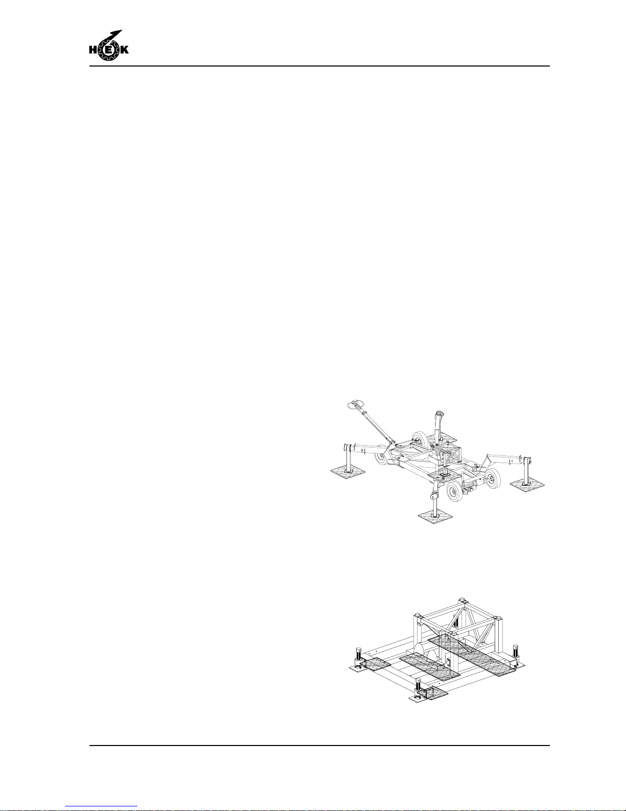
When a chassis is used, a ground support
must be placed under the jack close to the
mast and under the jack of the 4 extending
legs. The frame must have a support
placed under the mast and under the 4
corners (not under the jacks).
4. The ground support must be durable
and of such a quality that the load can
be transferred without plastic
deformation.
5. If the machine is installed on a
concrete foundation or on a hard
road surface, the installation must be
provided with wooden packing to
prevent slipping.
Fig.6-2 Ground support chassis
Fig.6-3 Ground support ground frame
Page 40
ASSEMBLY AND ANCHORING
6-4 MSHF • 7295-026A
6.3 Positioning the mast climbing
work platform
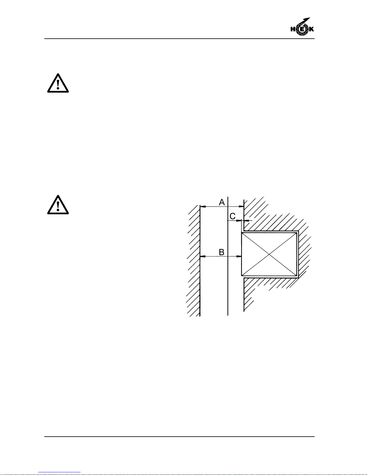
A fence (height 1.10 m / 43.3 in)
completely surrounding the
platform is compulsory . If the
distance between the platform
and the facade is 0.3 m - 0.5 m /
1 1.8 in - 19.7 in a fence with a
height of 0.7 m / 27.6 in can be
used. If the distance between the
platform and the facade is less
than 0.3 m / 1 1.8 in a fence is not
compulsory but in this case a
kick board with an height of
0,15m / 5.9 in must be fitted.
Wheels of the chassis should not
have a bearing function while
assembly and operating the
platform.
Distance to the facade with standard
anchoring.
A = 575 - 1300 mm / 22.6 - 51.2 in
B = 550 - 1275 mm / 21.7 - 50.2 in
C = 25 mm / 1 in
There are four ways in which the mast
climbing work platform can be placed:
- single mast, freestanding (chassis
mounted)
- single mast, anchored (chassis or
ground frame mounted)
- two masts, freestanding (chassis
mounted)
- two masts, anchored (chassis or ground
frame mounted).
Fig.6-4 Distance to the facade
Page 41
ASSEMBLY AND ANCHORING
6-5MSHF • 7295-026A
6.3.1Mast climbing work platform with
single mast on a chassis
1. Position the chassis parallel to the
wall.
2. Withdraw the outriggers on the step
side and secure them. Withdraw the
outriggers on the side nearest the
wall as far as possible. The maximum
height for a freestanding machine
depends on the position of the
outriggers and the loading (see
loading diagram, chapter 1.5).
3. Place the ground supports.
4. Unscrew the jack until the wheels no
longer contact the ground and adjust
the machine to be level. The
measurement must be done with a
spirit level with a minimum length of 1
meter / 40 inch.
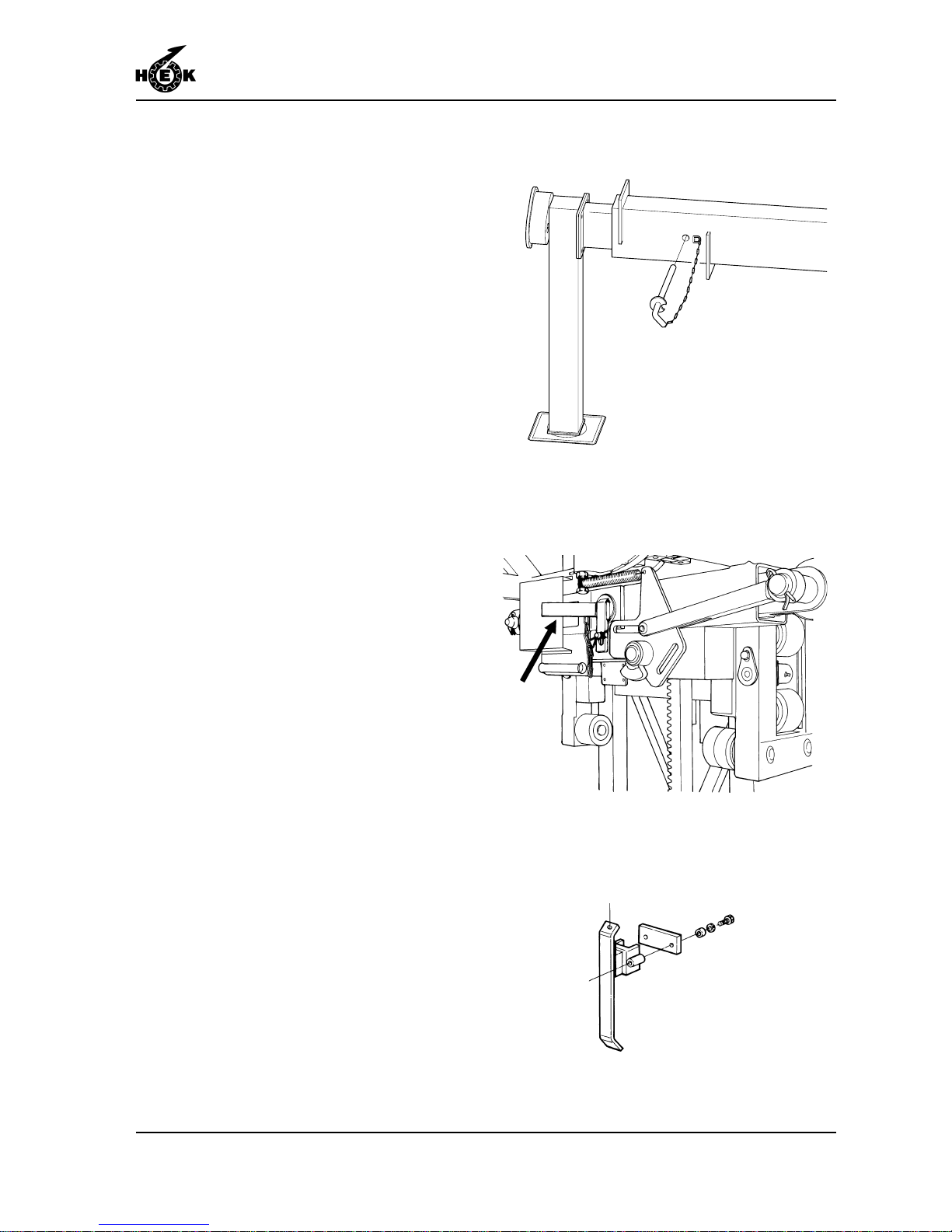
5. Check that the locking pin for
securing the autolevel device and the
lower striker plate are mounted.
6. Assemble the platform components
sequentially on both sides until the
desired length is attained. The
platform may not exceed the
maximum length.
7. Tighten the platform bolts until the
specified torque is applied.
8. The width of the platform can be
adjusted to fit the form of the façade.
See section 6.6.
Fig.6-5 Locking pin outrigger chassis
Fig.6-6 Autolevel locking pin
Fig.6-7 Lower striker plate
Page 42
ASSEMBLY AND ANCHORING
6-6 MSHF • 7295-026A
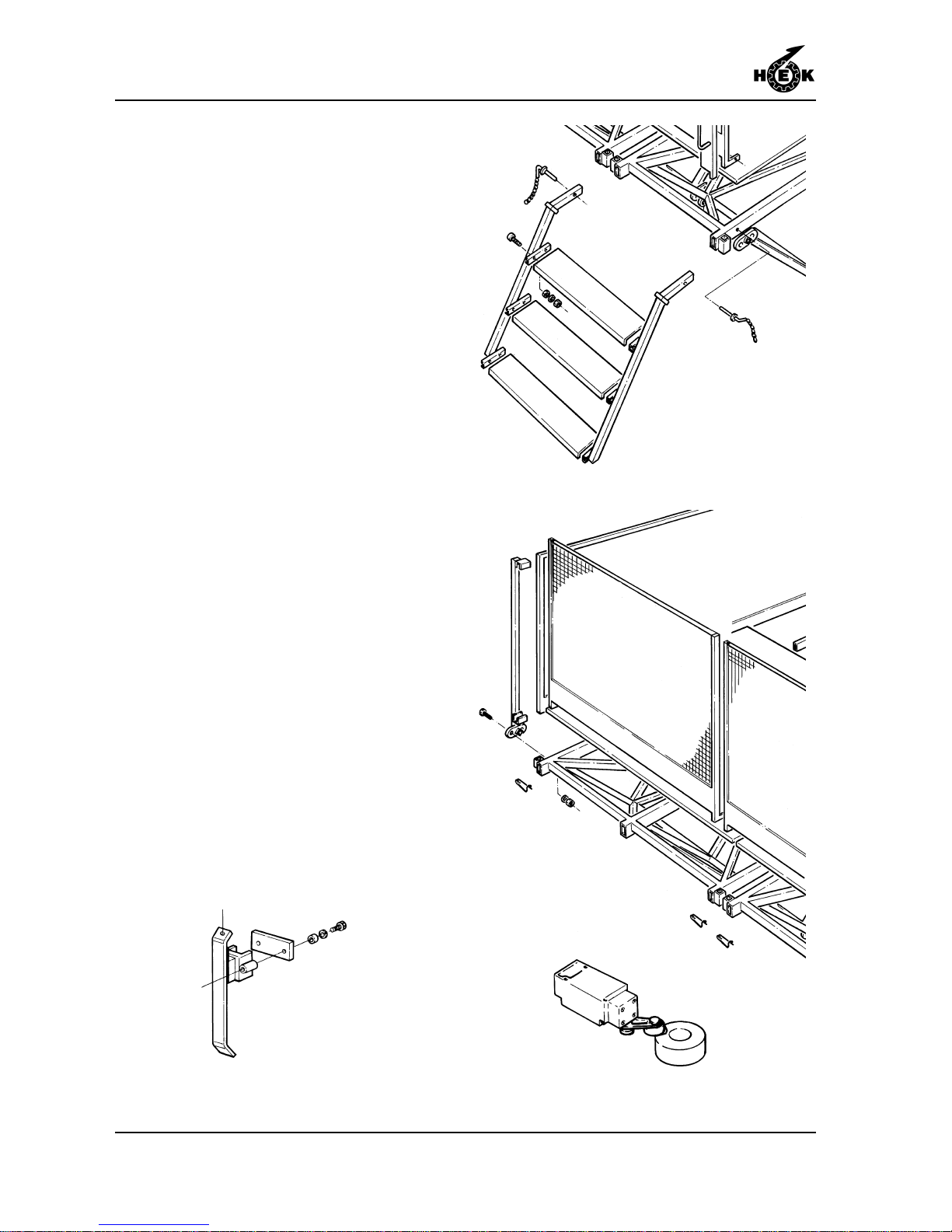
9. Mount the steps and secure them
with locking pins.
10. Mount the fencing and secure it with
"hairpins".
1 1. Mount the gate and the cam for the
gate safety switch. The roller must fall
into the cam when the gate is closed
6.3.2Mast climbing work platform with
one mast on a ground frame
1. Position the ground frame parallel to
the wall.
2. Place the ground supports.
3. Level the machine using the jacks.
Ensure that the mast is vertical in
both directions by checking with a
spirit level (with a length of at least 1
metre / 40 inch) placed against two
adjacent sides of the mast. Place
wooden packing under the machine
to provide optimum load spreading
and stability .
Fig.6-9 Step
Fig.6-10 Fence
Fig.6-1 1 Gate safety switchFig.6-8 Lower striker plate
Page 43
ASSEMBLY AND ANCHORING
6-7MSHF • 7295-026A
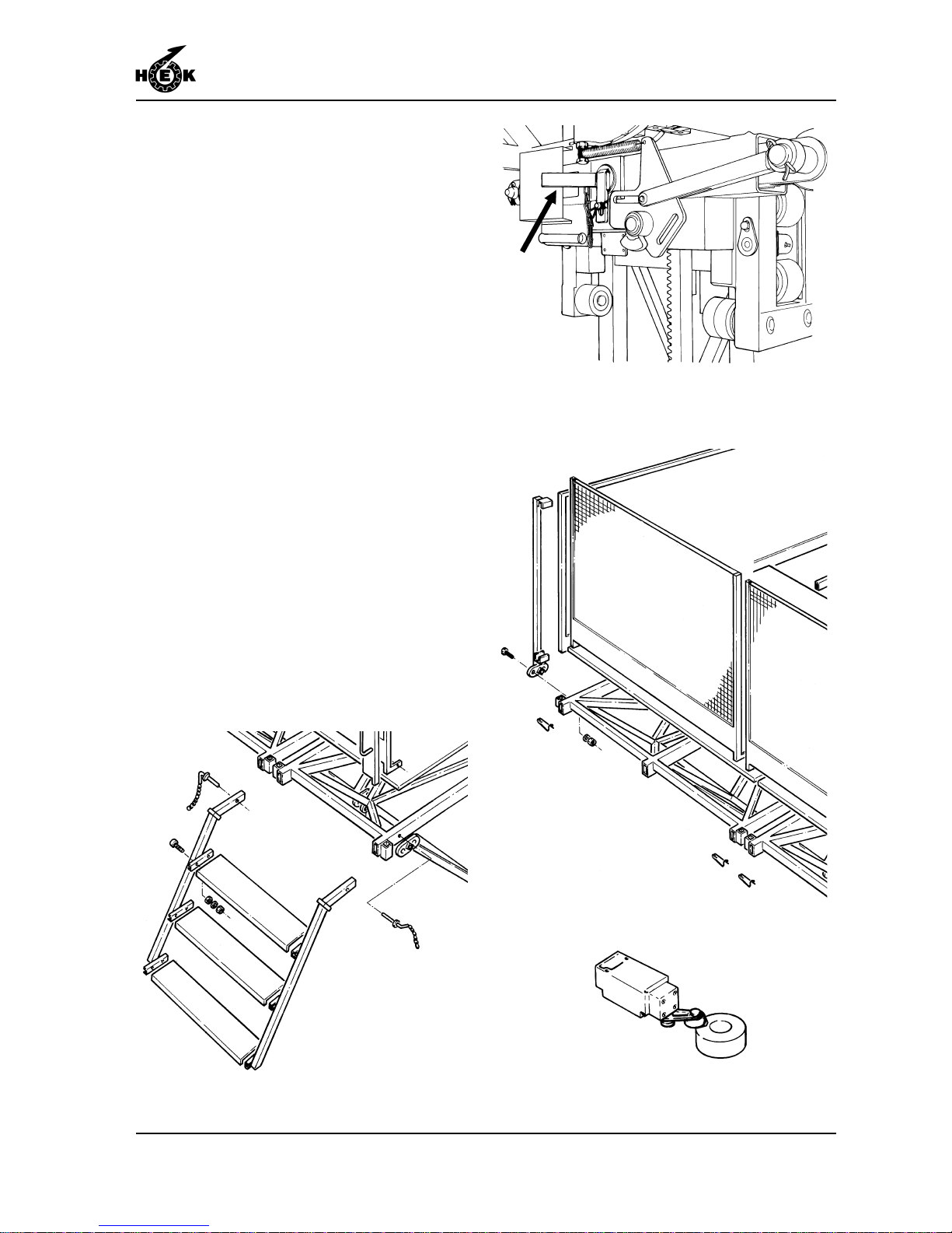
4. Check that the locking pin for
securing the autolevel and the lower
striker plate are mounted.
5. Assemble the platform components
sequentially on both sides until the
desired length is attained. The
platform may not exceed the
maximum length.
6. Tighten the platform bolts until the
specified torque is applied.
7. The width of the platform can be
adjusted to fit the form of the façade.
See section 6.6.
8. Mount the steps and secure them
with locking pins.
9. Mount the fencing and secure it with
"hairpins".
10. Mount the gate and the cam for the
gate safety switch. The roller must fall
into the cam when the gate is closed.
Fig.6-12 Step
Fig.6-14 Fence
Fig.6-15 Gate safety switch
Fig.6-13 Autolevel locking pin
Page 44
ASSEMBLY AND ANCHORING
6-8 MSHF • 7295-026A
6.3.3Mast climbing work platform with
two masts on a chassis
One drive unit must be adjusted
for "left" and the other for "right".
1. Check that the left-hand machine is
adjusted for "left" and the right-hand
machine for "right". See section 6.7.
2. Position the chassis parallel to the
wall and with a separation to allow for
the required distance between the
masts + 1 metre / 3.3 ft.
3. Withdraw the outriggers on the step
side completely and secure them.
The outriggers on the side facing the
wall should be withdrawn as far as
possible.
The maximum freestanding height
depends on the position of the
telescopic arms and the loading (See
loading diagram, chapter 1.5).
4. Place the ground supports for this
chassis.
5. Unscrew the jack for this chassis until
the wheels no longer touch the
ground and level the machine. The
measurement must be done with a
spirit level with a minimum length of 1
meter / 40 inch.
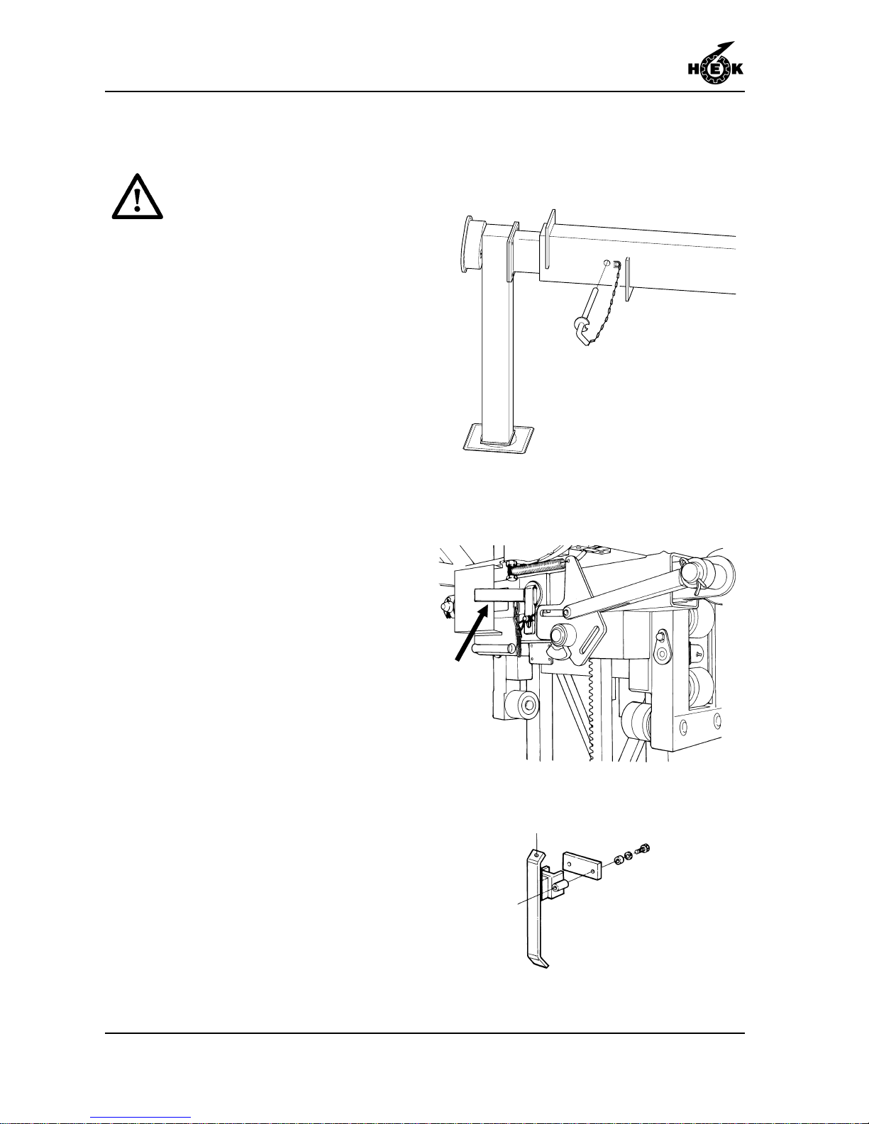
6. Check that the autolevel locking pins
and the lower striker plates are
mounted on both chassis.
Fig.6-18 Lower striker plate
Fig.6-17 Autolevel locking pin
Fig.6-16 Locking pin outrigger chassis
Page 45
ASSEMBLY AND ANCHORING
6-9MSHF • 7295-026A
7. Assemble the platform components,
by both chassis simultaneously on
both sides of the drive units until the
desired length is attained. The
platforms may not exceed the
maximum length.
8. Tighten the platform bolts until the
specified torque is applied.
9. Push the second chassis towards the
first and fix the platform elements
together.
10. Repeat steps 3 to 5 for the second
chassis.
1 1. The width of the platform can be
adjusted to fit the form of the façade.
See section 6.6.
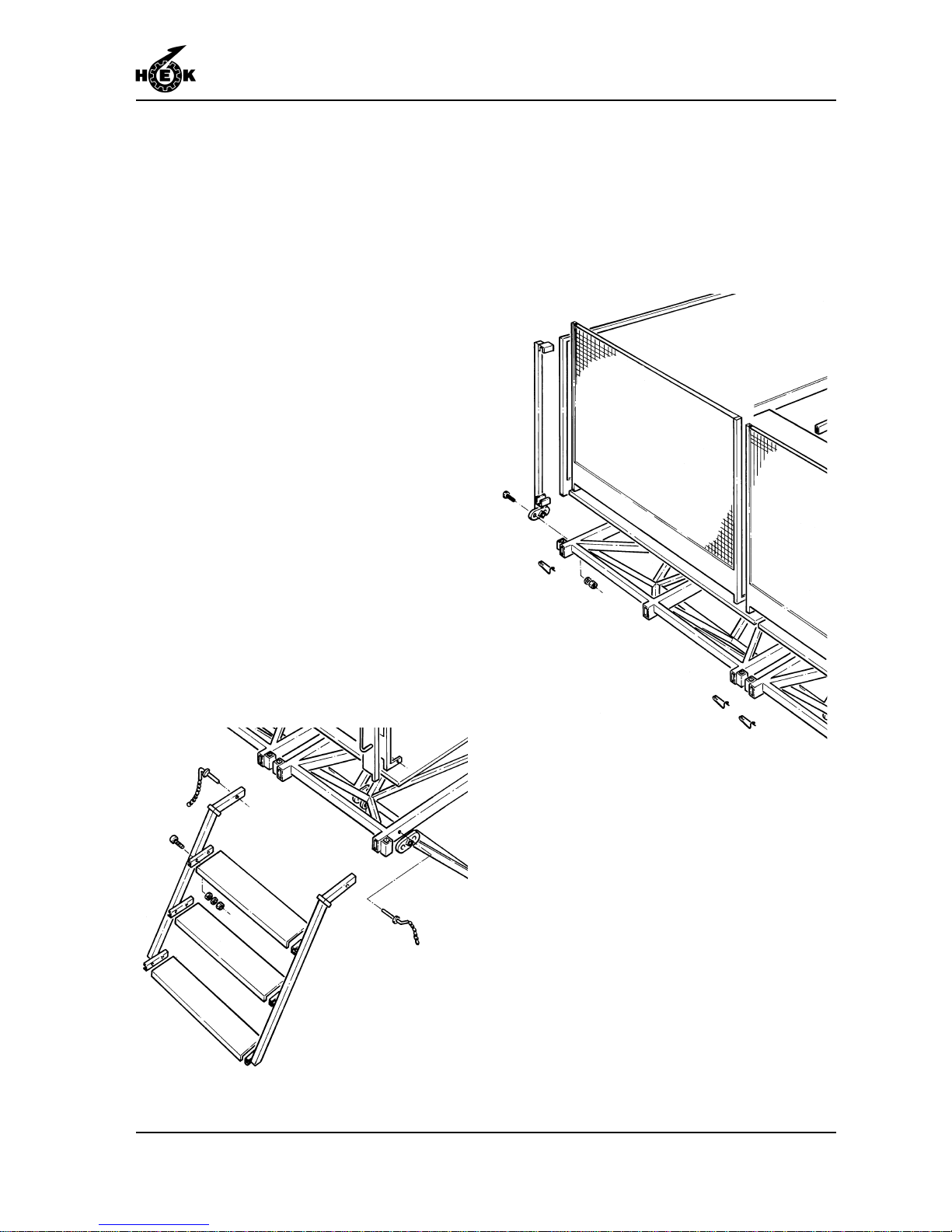
12. Mount the steps and secure them
with locking pins.
13. Mount the fencing and secure it with
"hairpins".
Fig.6-20 Fence
Fig.6-19 Step
Page 46
ASSEMBLY AND ANCHORING
6-10 MSHF • 7295-026A
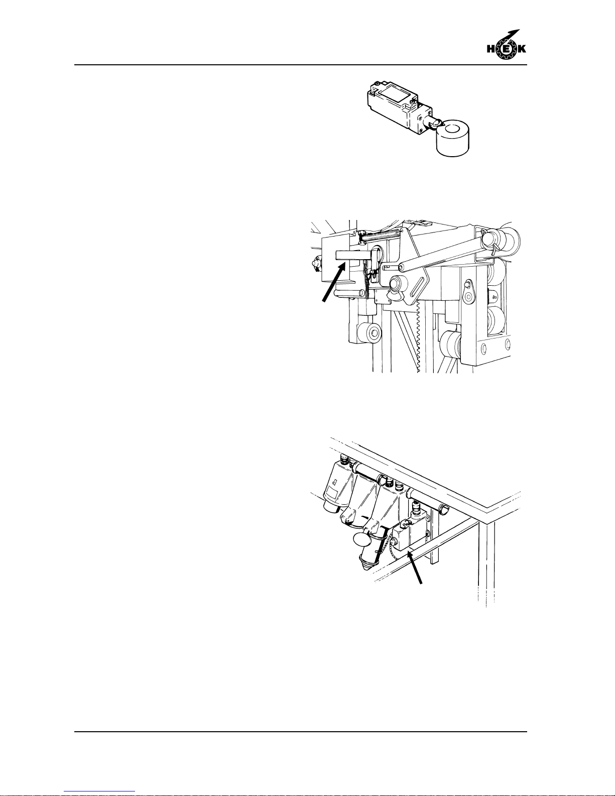
14. Mount the gate and the cam for the
gate safety switch. The roller must fall
into the cam when the gate is closed
15. Remove the autolevel locking pins
from both machines.
16. Remove the dummy plugs from the
control cable sockets.
17. Connect the control cable and the
electrical power supply cable. Secure
the cables to the underside of the
platform neatly so that they do not
hang down.
Fig.6-21 Gate safety switch
Fig.6-22 Autolevel locking pin
Fig.6-23 Control cable dummy plug
Page 47
ASSEMBLY AND ANCHORING
6-11MSHF • 7295-026A
6.3.4Mast climbing work platform with
two masts on ground frames
One drive unit must be adjusted
for "left" and the other for "right".
1. Check that the left-hand machine is
adjusted for "left" and the right-hand
machine for "right". See section 6.7.
2. Position the ground frames parallel to
the wall and with a separation to
allow for the required distance
between the masts.
3. Place the ground supports for both
ground frames.
4. Level the machine using the jacks.
Ensure that the mast is vertical in
both directions by checking with a
spirit level (with a length of at least 1
metre / 40 inch) placed against two
adjacent sides of the mast. Place
wooden packing under the machine
to provide optimum load spreading
and stability .
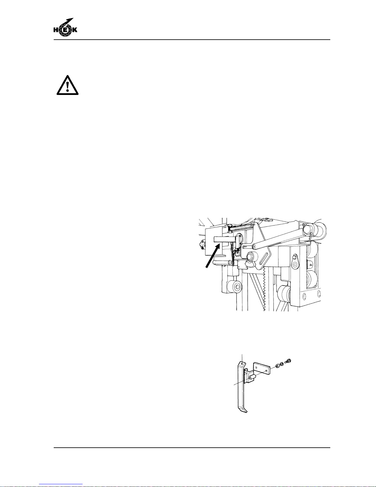
5. Check that the autolevel locking pins
for securing the parallel movement
and the lower striker plates are
mounted.
6. Assemble the platform components
sequentially on both sides of the drive
units until the desired length is
attained. The platform may not
exceed the maximum length.
7. Tighten the platform bolts until the
specified torque is applied.
8. Assemble the second ground frame
to the first by fixing the platform
elements together.
Fig.6-24 Autolevel locking pin
Fig.6-25 Lower striker plate
Page 48
ASSEMBLY AND ANCHORING
6-12 MSHF • 7295-026A
9. The width of the platform can be
adjusted to fit the form of the façade.
See section 6.6.
10. Mount the steps and secure them
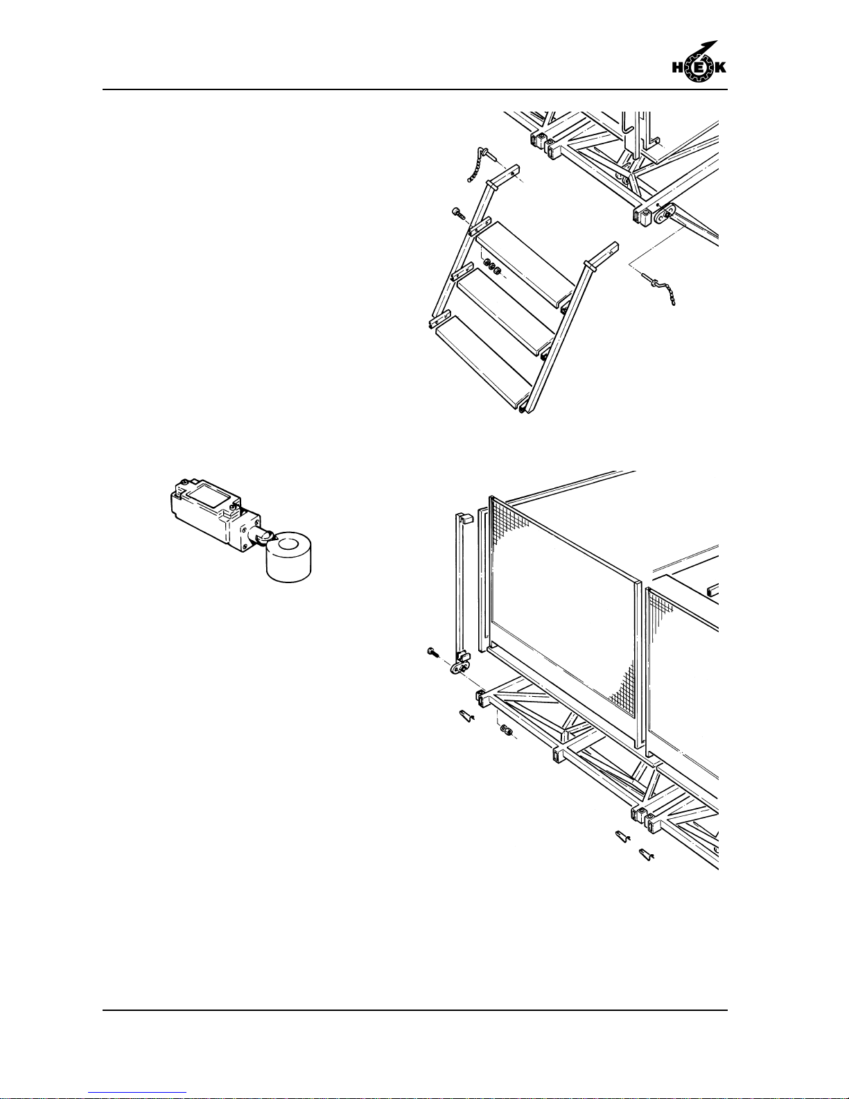
with locking pins.
1 1. Mount the fencing and secure it with
"hairpins".
12. Mount the gate and the cam for the
gate safety switch. The roller must fall
into the cam when the gate is closed.
Fig.6-26 Gate safety switch
Fig.6-27 Step
Fig.6-28 Fence
Page 49
ASSEMBLY AND ANCHORING
6-13MSHF • 7295-026A
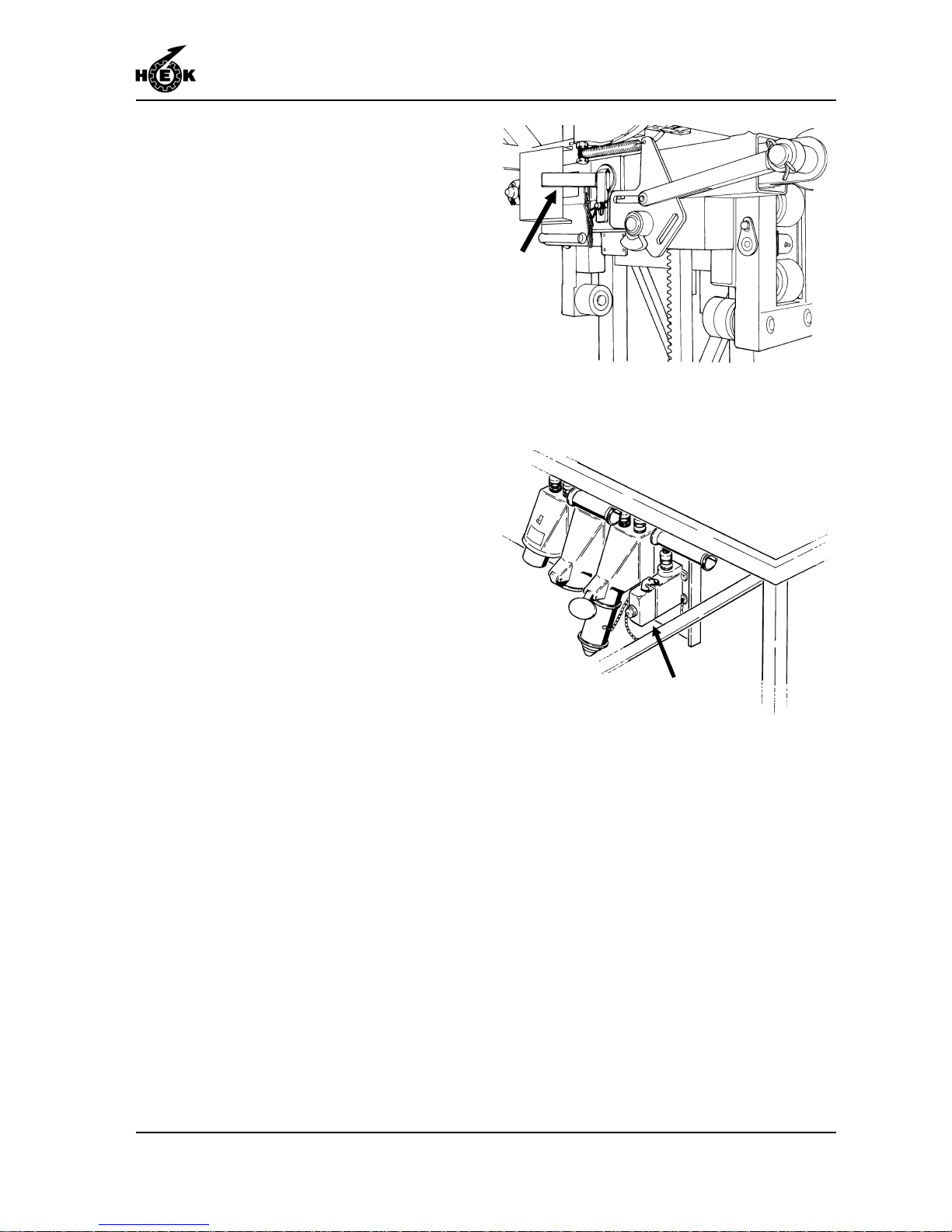
13. Remove the autolevel locking pins
from both machines.
14. Remove the dummy connecting plugs
from the control cable sockets.
15. Connect the control cable and the
electrical power supply cable. Secure
the cables to the underside of the
platform neatly so that they do not
hang down.
Fig.6-29 Autolevel locking pin
Fig.6-30 Control cable dummy plug
Page 50
ASSEMBLY AND ANCHORING
6-14 MSHF • 7295-026A
6.4 Assembly of the mast
If work has to be stopped, always
complete the phase being
worked on. Tighten all the bolts
used for the last attachment and
switch off and secure the main
switch so that the machine
cannot be operated.
As the assembly proceeds,
place the anchor tubes, anchors
and cable guides as described
in section 6.5
Note that the power supply
consists of
3 x 400 V + neutral + safety
earth.
The mast(s) must always be
assembled vertically .
In winds of strengths above
6 Beaufort (12,5 m/s) (41 ft/s) the
machine may not be assembled.
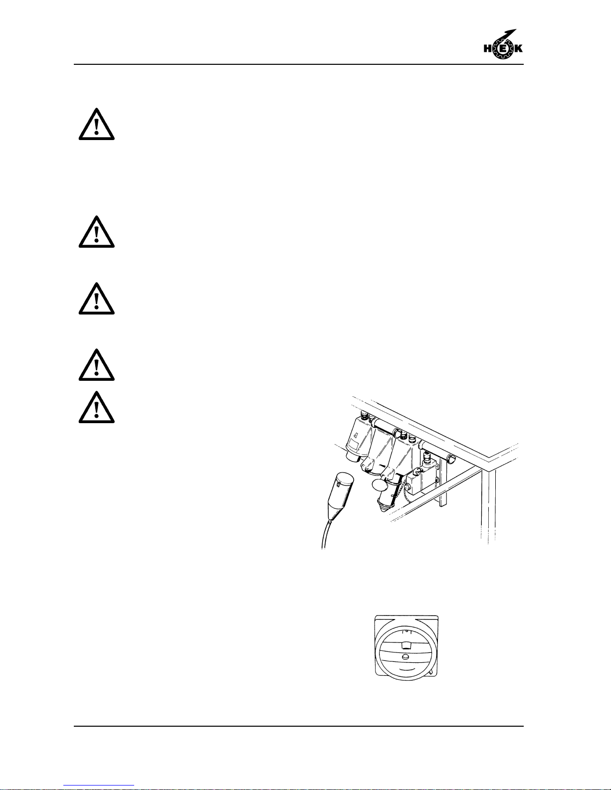
1. Connect the power supply to the
machine.
2. Set the main switch in position I or II
(the position depends on the
direction of phase rotation of the
power supply). If the display shows
code 02 and the phaselight on the
phaseguard relay does not burn, set
the main switch in the other position.
The display must show code 00 and
the phase light will be burning.
Fig.6-31 Power supply
Fig.6-32 Main switch
Page 51
ASSEMBLY AND ANCHORING
6-15MSHF • 7295-026A
3. When the mast climbing work
platform is delivered it is in the buffer .
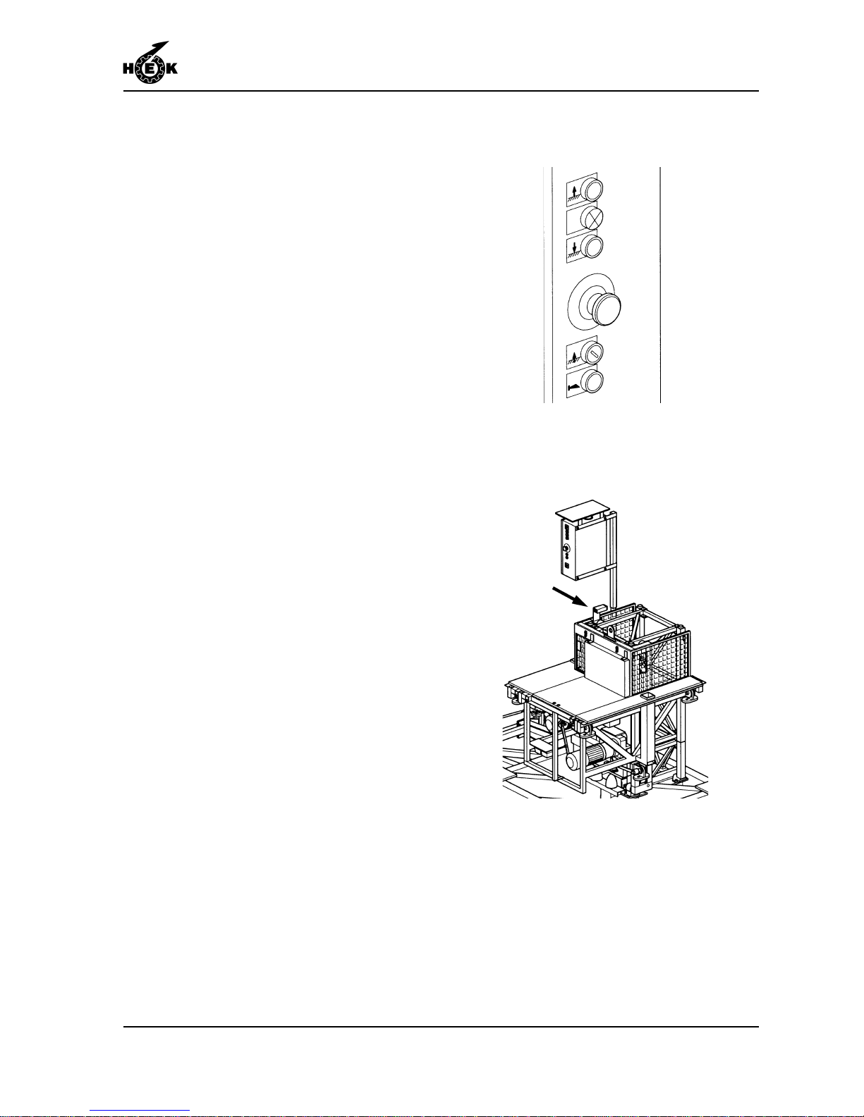
In order to remove the mobile work
platform out of the buffer , carry out the
following procedure:
1 Press the push-button "reset
positioning" and keep it pushed in.
2 Press the push-button "UP".
For a two-mast construction, check
that the lower striker plates and the
autolevel switches are properly
adjusted. See sections 6.8 and 6.9.
4. The mast climbing work platform is
raised and lowered by pressing the
UP and DOWN push buttons. When
the push-button is released, the mast
climbing work platform stops. In
addition, an emergency stop pushbutton is provided. When this button
is pushed, the power of the motors
will be shut off.
5. Check that the proximity switch is
mounted on both drive units.
6. Use a fork-lift truck or crane to raise
the mast elements onto the platform.
Ensure that the maximum loading
permitted during assembly is not
exceeded.
7. Stand on the platform and use the
crane to place a mast element on the
last element assembled. Secure the
mast element with four bolts, washers
and nuts. Tighten the bolts to the
specified torque value.
(See chapter 1)
Fig.6-34 Proximity switch
Fig.6-33 Control buttons
Page 52
ASSEMBLY AND ANCHORING
6-16 MSHF • 7295-026A
8. Raise the platform towards the top of
the mast element and repeat the
procedure until another element must
be assembled. Plan the procedure
so that, when an anchor must be
fitted, the loading of material and
mast elements is a minimum.
9. Ensure that anchors are placed at the
specified intervals.
10. Repeat this working method until the
mast has reached the required
height. The last element assembled
must always be the red top element.
The maximum specified height must
not be exceeded.
1 1. If a crane is available on the building
site, the mast can be more quickly
assembled. Up to five mast elements
can be assembled on the ground and
then raised into position with the
crane.
12. The mast must not extend too far
above the uppermost anchor (See
chapter 1). T o achieve good stability ,
it is always better to place an anchor
as close to the top of the mast as
possible.
13. Assemble the mast cover panels
from the platform and secure them.
14. The assembly is now complete. The
assembly must now be tested as
described in section 7.1
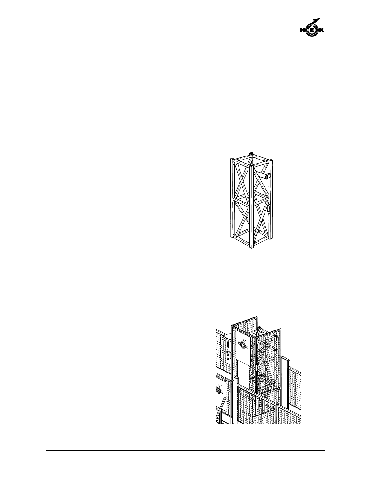
Fig.6-35 Red top mast element
Fig.6-36 Mast cover
Page 53
ASSEMBLY AND ANCHORING
6-17MSHF • 7295-026A
6.5 Anchoring the mast
If work must be stopped, always
complete the current phase
before stopping. Tighten all the
bolts for the latest fixture and
secure the main switch so that
the mast climbing work platform
cannot be operated.
Before starting to fix any
anchors, ensure that the chassis/
ground frame is level.
The wall must be of such a
quality that it can accept the
forces applied to it via the
anchors.
The platform extensions and the
anchors must not come into
contact during raising and
lowering.
The anchor forces must be
approved by the owner or the
person responsible for the
building to which the machine will
be anchored.
1. Check that the mast is vertical with a
spirit level at least 1 metre / 40 inch
long. Recheck as each anchor is
secured.
2. The mast must be anchored to the
building at the distances specified in
the table in chapter 1.
3. The anchors are assembled from
mast adapters, horizontal anchor
tubes and a support tube.
Page 54

ASSEMBLY AND ANCHORING
6-18 MSHF • 7295-026A
4. The horizontal anchor tubes and the
support tubes can be supplied in
various lengths.
5. Fixing the anchors:
- Anchoring is carried out using bolt
couplings, nut and bolt fastenings
and washers. If conditions make it
necessary , use may be made of
other approved attachment
materials which are suitable for the
forces present. (Consult your
dealer).
- Cemented-in anchors must be
allowed to become fully secure
(the cement must have time to
harden) before the mast climbing
work platform is assembled. The
cement or concrete used must be
in accord with the specifications.
- If chemical anchors or expansion
bolts are used, these must be
approved and must be able to
withstand the forces involved.
- Specifications for these types of
bolts are available from the
supplier. Permission to use them
must be obtained from the local
authorities.
Page 55
ASSEMBLY AND ANCHORING
6-19MSHF • 7295-026A
6. Securing the anchors:
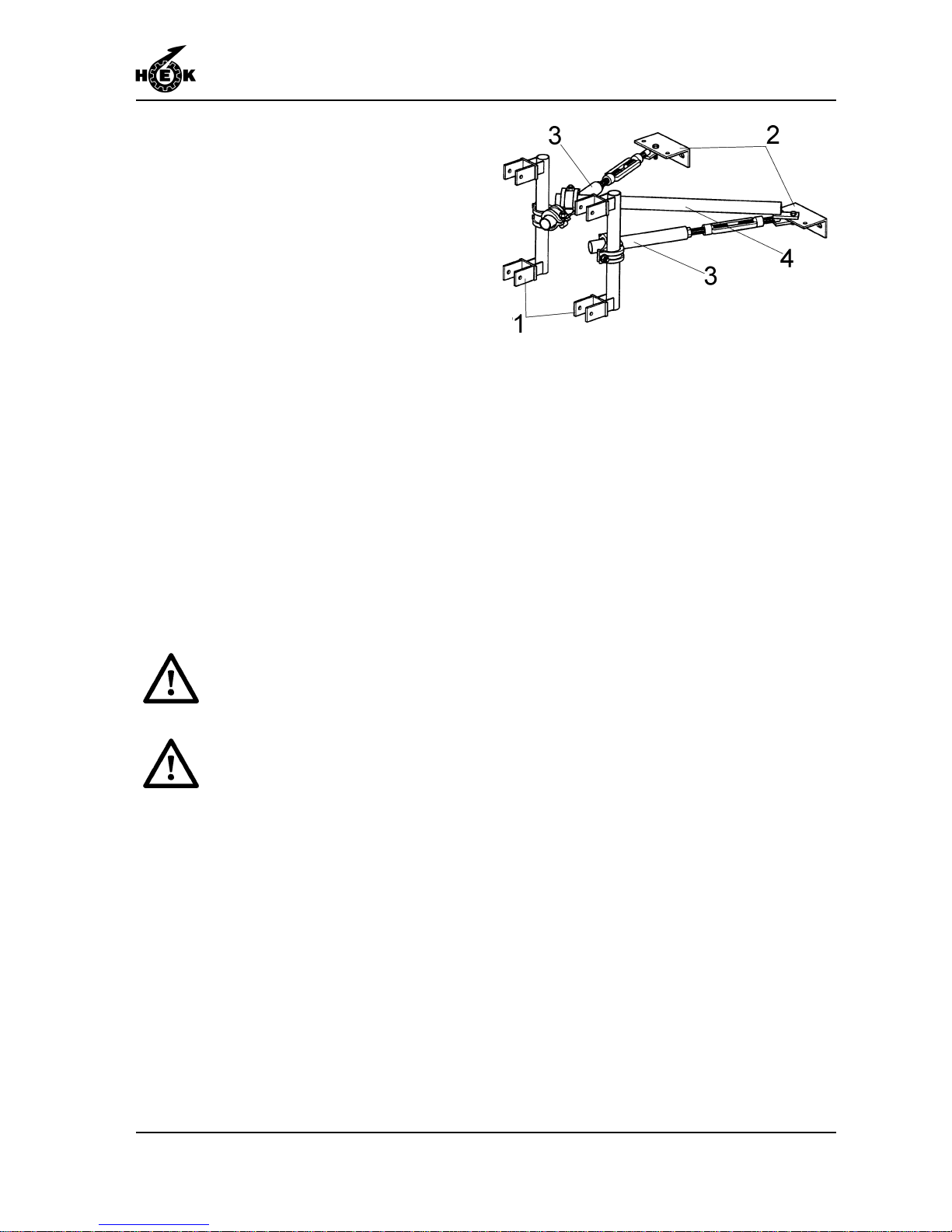
- Secure the mast adapters (1) to
the mast.
- Fix the wall plates (2) to the
building.
- Secure the horizontal anchor tubes
(3) between the mast adapters
and the wall plates.
- Tighten the horizontal anchor tube
couplings to the correct torque
value.
- Use the adjustment construction to
set the mast vertical and parallel to
the building.
- Fix the support tube (4).
6.6 Adjusting the platform width
The width of the platform can be adjusted
to the shape of the building. As standard
an extension of 1 metre / 3.3 ft is possible.
In case work must carry out behind the
mast a anchor ramp must be mounted.
The planks used for adjusting the
platform must in every case be
secured in every direction.
The platform widening and the
mast anchors must not come into
contact when the platform is
raised and lowered.
Fig.6-37 Anchoring
Page 56
ASSEMBLY AND ANCHORING
6-20 MSHF • 7295-026A
A fence (height 1.10 m / 43.3 in)
completely surrounding the
platform is compulsory . If the
distance between the platform
and the facade is 0.3 m - 0.5 m /
1 1.8 in - 19.7 in a fence with a
height of 0.7 m / 27.6 in can be
used. If the distance between the
platform and the facade is less
than 0.3 m / 1 1.8 in a fence is not
compulsory but in this case a
kick board with an height of
0,15m / 5.9 in must be fitted.
The platform extension must be in
accordance with specification prEN1495.
The platform extension must be fabricated
from a non-slip, easily cleaned material.
The extension must be self draining. The
width of any openings or gaps in the floor
must be sufficiently narrow that a ball with a
diameter of 15mm will not pass through.
The platform extension must be able to
withstand a static load of 200kg / 440 lb on
an square area of 0.1x0.1m / 0.4 x 0.4 inch
on the least favourable part of the floor
surface without causing any permanent
distortion.
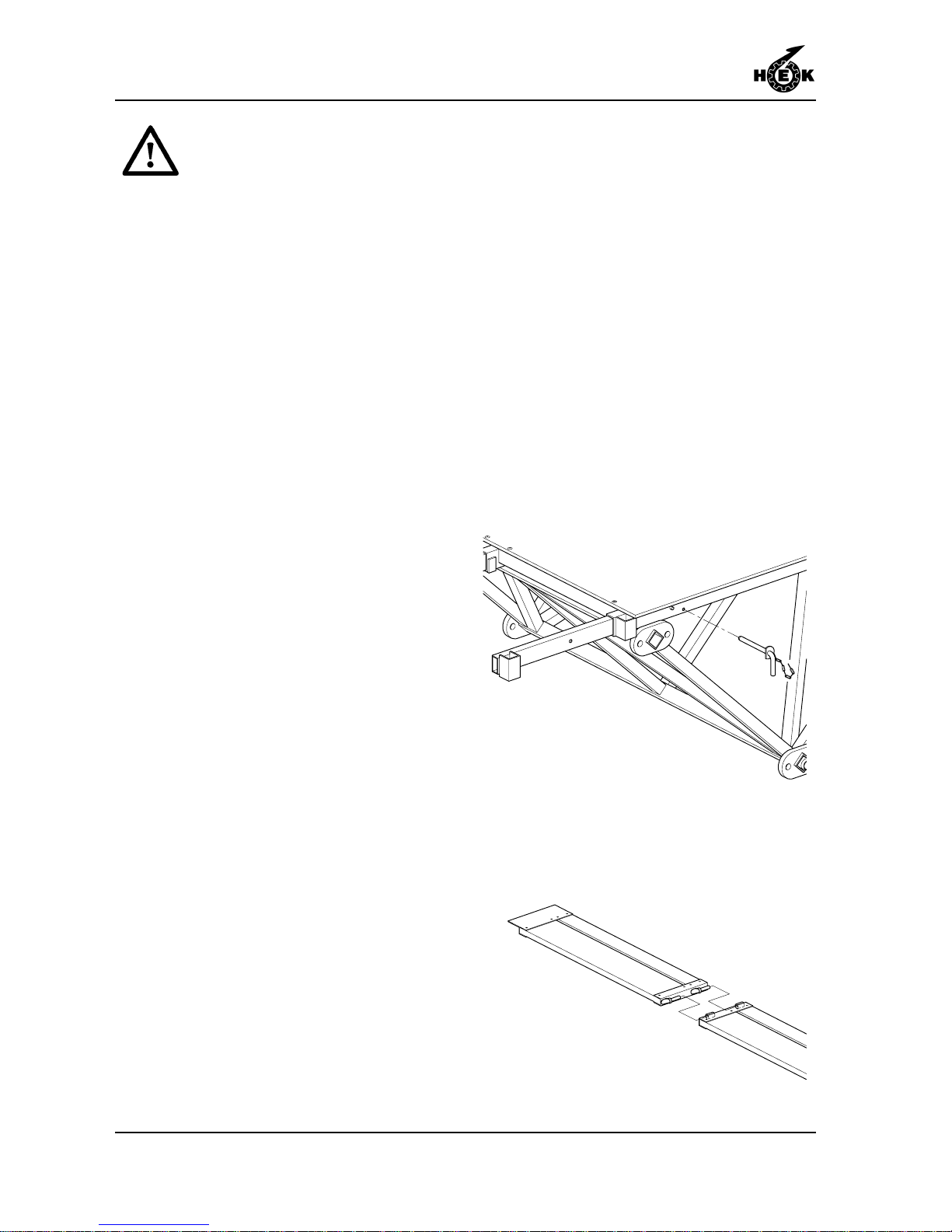
1. Pull out the outriggers and secure
them with locking pins.
2. Cover the outriggers with planks.
3. Fix cross strips with a right-angle
profile to the underside of the
planking and secure them to the
outriggers.
4. Mount the anchor ramp to the
outriggers.
Fig.6-39 Anchor ramp
Fig.6-38 Outrigger platform extension
Page 57
ASSEMBLY AND ANCHORING
6-21MSHF • 7295-026A
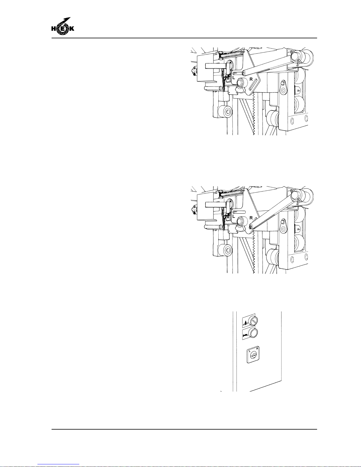
Fig.6-40 Machine setting left
Fig.6-41 machine setting right
Fig.6-42 switch left/right setting
6.7 Setting the machine left or right
The factory setting is stated on the type
plate fixed to the control box. An "R" in the
machine number indicates right and an
"L" indicated left.
The setting can be adjusted in the
following way .
1. Insert the operating bar of the
parallel movement mechanism in
the required slot (left or right).
2. Set the switch on the control box in
the required position (left or right).
Page 58
ASSEMBLY AND ANCHORING
6-22 MSHF • 7295-026A
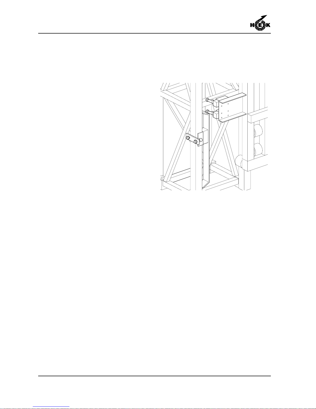
Fig.6-43 Adjusting lower striker plate
6.8 Checking and adjusting the lower
striker plates
For a two-mast construction, the striker
plates must be checked and if necessary ,
adjusted.
1. Lower the highest placed unit until the
limit switch just touches the lower
striker plates.
2. Use the other unit to level the
platform.
3. Check that the limit switch just
touches the lower striker plate for this
unit.
4. If the lower striker plate does not
touch the limit switch, adjust the
position of the striker plate until it just
touches the limit switch.
5. Check the adjustment.
Page 59
ASSEMBLY AND ANCHORING
6-23MSHF • 7295-026A
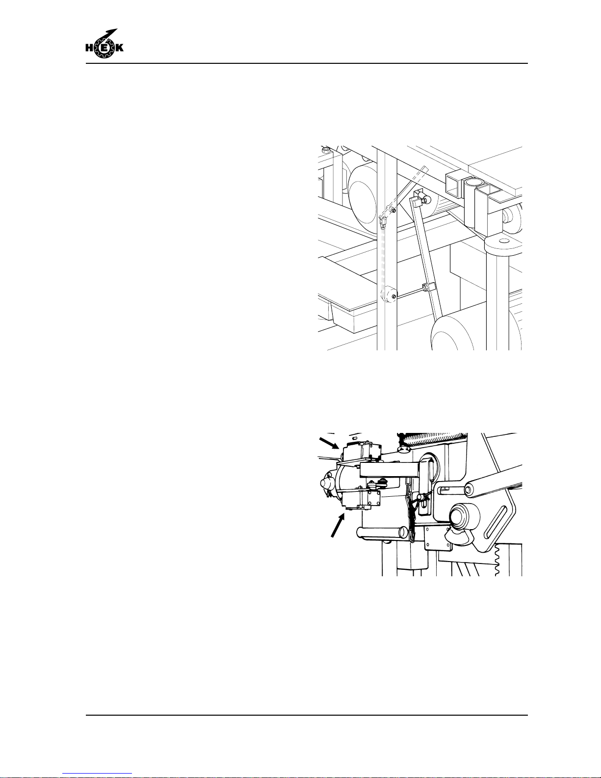
Fig.6-44 Brake lever drive unit
Fig.6-45 Autolevel switches
6.9 Checking the autolevel switches
For a twin mast construction, the autolevel
switches must be checked and adjusted if
necessary .
1. Raise the platform by 3 metres /
9.8 ft and level the platform by means
of the brake lever.
2. Operate the brake release on one
drive unit and, depending on the
distance between the centres of the
masts, allow the unit to descend.
Distance between centres 730 cm /
24 ft : 25,5 cm / 10.0 in lower .
Distance between centres 1330 cm /
43.6 ft: 46 cm / 18.1 in lower .
These distances represent a platform
slope of 2 degrees.
3. Operate the "UP" push-button on the
platform. The lowest unit must now be
the first to rise.
4. Repeat the previous steps for the
other unit.
5. If necessary , adjust the switches.
Page 60
ASSEMBLY AND ANCHORING
6-24 MSHF • 7295-026A
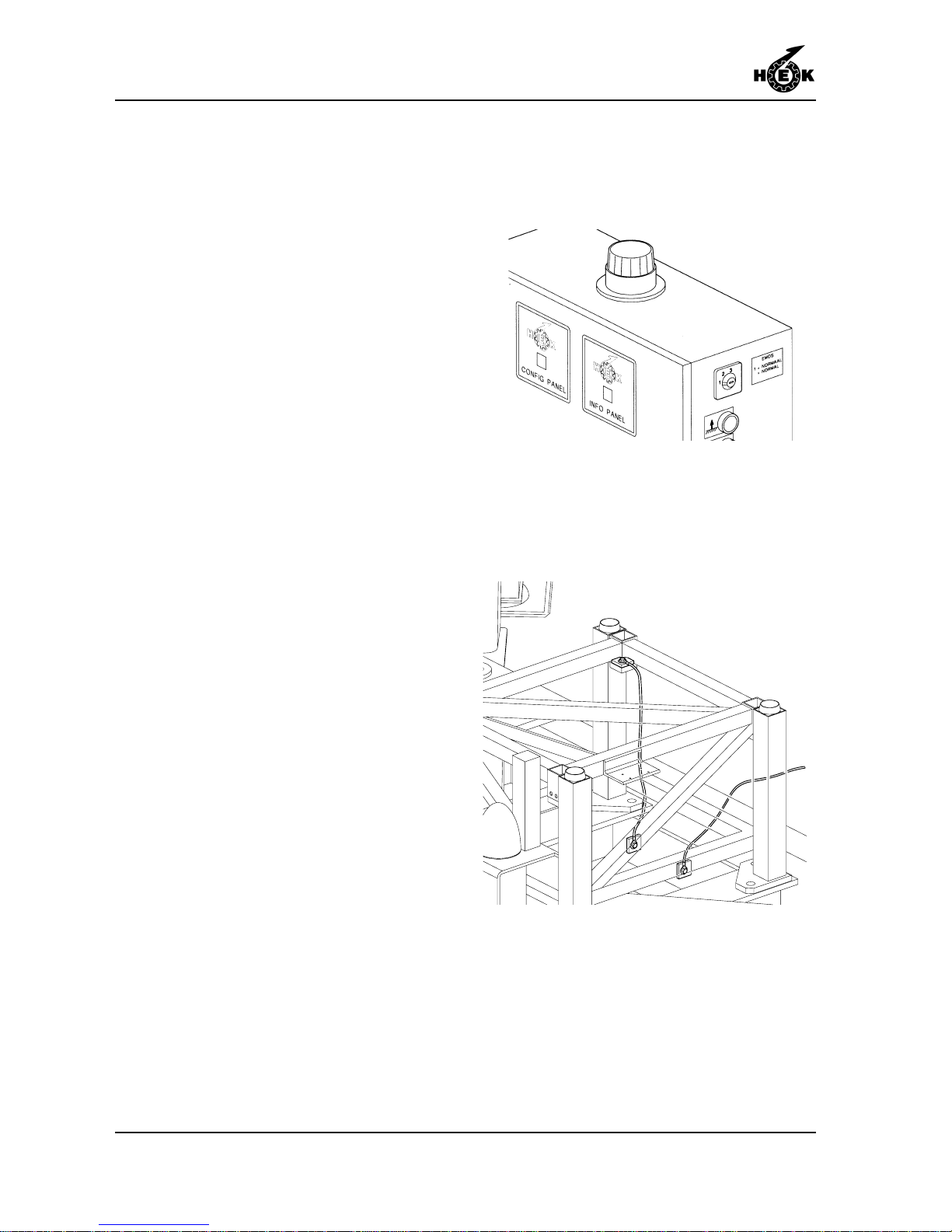
Fig.6-47 Lightning protection
6.10 Adjusting the EMOS system
1. The switch can only been turned with
the correct key . Set the EMOS switch
(1,2,3) in position 2. The config panel
starts to flash.
2. The program can be changed with
the UP or DOWN button on the
control box.
3. Set the desired program
(See table chapter 1.7).
4. Set the EMOS switch on position 1.
5. The config panel shows the adjusted
value.
6. Remove the key .
6.1 1 Lightning protection
1. Fasten the connecting cable between
the chassis/ground frame and the
mast.
Cable specifications:
- Insulated copper, 16 mm² cross
section.
2. Mount the connection between the
chassis/ground frame and the earth.
This connection must satisfy the
following specification:
DIN VDE 0185, part II, §5.2
The cable supplied (25 mm² / 0.0039
in² cross section, 25 m / 82 ft long)
must be connected to the terminal
box on the building site.
Fig.6-46 Adjusting EMOS
Page 61

OPERATION
7-1MSHF • 7295-026A
7. OPERATION
7.1 General
No person may stand under the
machine while it is in use.
Material may never extend
beyond the edges of the
platform. Items which can roll
must be properly secured. The
load may never be supported
against the fencing.
The maximum reaction force (for
instance caused by tools) of the
platform with regard to the
facade amounts for a single
mast machine 500 N / 1 13 lbf
and for a twin mast machine 800
N / 180 lbf.
When work stops for any reason,
the main switch must be secured
with the padlock.
During rising or descending no
person may stand on the
platform extensions.
7.2 Preparation
1. Before the mast climbing work
platform is used it must be visually
inspected (daily if it is used every
day) for:
- anchors and cable guides
- presence of all security devices
- connection between mast
elements
- position of the masts
- any loose components
Page 62
OPERATION
7-2 MSHF • 7295-026A
- ground supports and the quality of
the ground
- electrical connections
- protective covers (presence and
securing)
- securing of the platform extension
- operation of the limit switches
- no obstacles in the path of the
platform
- oil leaking from the drive units and
chassis motor
- functioning of the motor brakes
(section 7.4).
2. Connect the electrical power supply .
3. Close the gates.
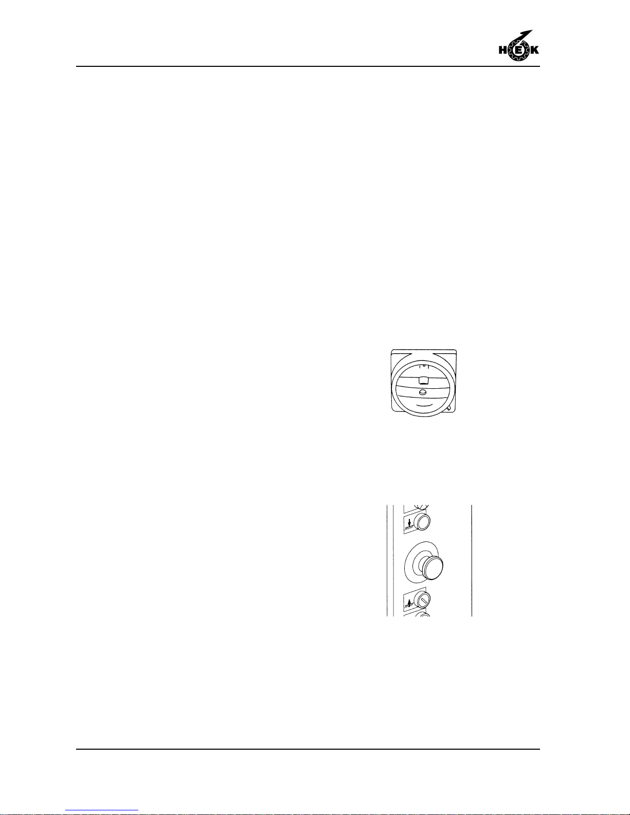
4. Remove the padlock from the main
switch.
5. Place the main switch in position I or
II (the position depends on the
direction of phase rotation of the
power supply).
6. Check that the EMERGENCY pushbutton on the control box is switched
off (the push-button must be pulled
out). On a twin mast unit release both
emergency push buttons.
7. If the display shows code 02 and the
phasegaurd light does not burn, the
main switch must be set in the other
position. The display will show code
00. If the electric safety circuit (gates,
etc.) is closed the blue light on the
control box will burn.
Only single-mast. Eccentric overload
check:
During a few seconds there will be
sounding a buzzer and a light will
flash on the control box.
Fig.7-1 Main switch
Fig.7-2 Emergency push-button
Page 63
OPERATION
7-3MSHF • 7295-026A
8. If a two-mast construction is used
with two different types of Control
boxes (one with a display and one
without), the ON push-button must be
pressed each time the platform is
raised or lowered. If the platform must
be controlled by the control box
without a display .
7.3 Testing
1. T est the platform and check the
following:
- all limit switches, striker plates and
safety devices and ensure that
everything is properly adjusted.
- that the path of the platform is not
obstructed.
- the functioning of all the push
buttons on the control box.
- the free movement of the power
supply cable.
Also test the platform brakes. (see
section 7.4)
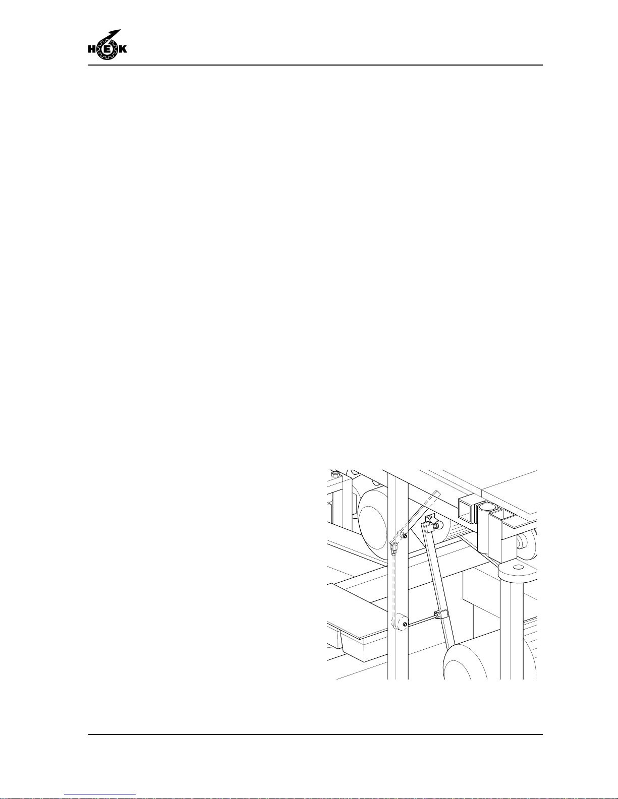
7.4 Brake test
The brake test must be carried out daily .
1. Release the brake on one of the
motors by pulling the lever on the
motor. The platform may not
descend. Release the brake lever .
2. Release the other brake. The
platform should not descend.
Release the brake lever .
Fig.7-3 Brake lever drive unit
Page 64
OPERATION
7-4 MSHF • 7295-026A
3. Repeat the previous two steps for the
other drive unit.
If the platform descends, the
mast climbing work platform
must not be used. Consult the
service engineer.
7.5 Operation from the platform
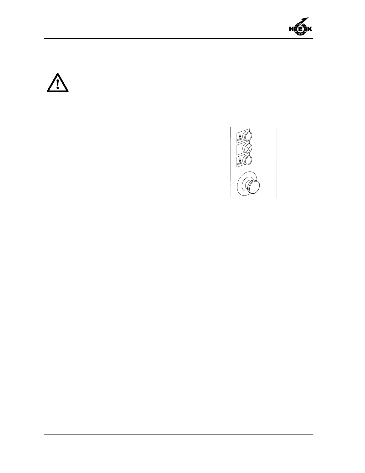
UP: If this push-button is
pressed, the platform is
raised. When the
push-button is released,
the platform stops
immediately.
DOWN: If this push-button is
pressed, the platform is
lowered. When the
push-button is released,
the platform stops
immediately.
EMERGENCY: When this push-button is
pressed, the platform is
locked.
7.6 Operation in an emergency
situation
In an emergency , for example in the event
of a power failure, the platform can always
be lowered.
- Using the malfunction analysis in
chapter 10, try to solve the problem. If
the problem can not be solved it is
possible to make a emergency descent
in the following way .
Fig.7-4 Push-buttons control box
Page 65
OPERATION
7-5MSHF • 7295-026A
1. Open the trap door in the platform.
2. Remove the toolbox.
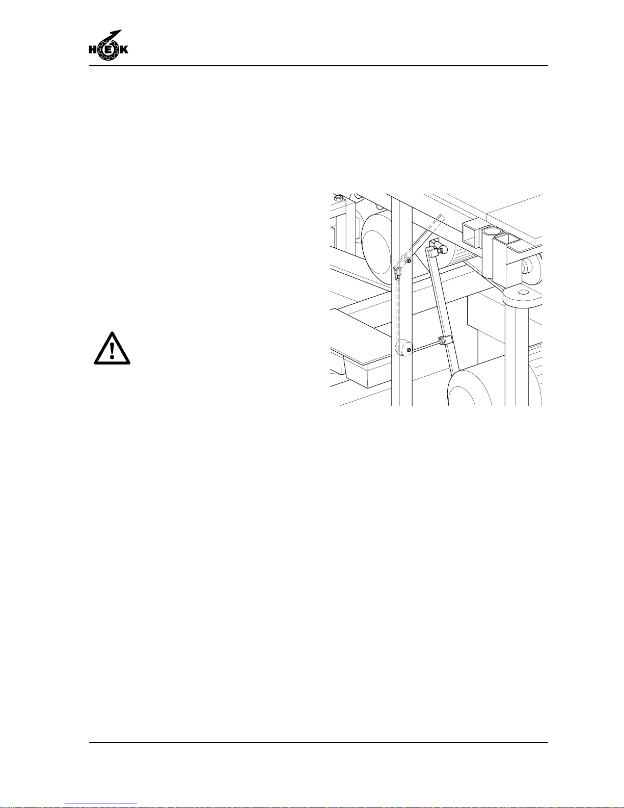
3. The motors have a lever which
permits the brake to be released.
4. When this lever is operated, the
platform will begin to descend. For a
two-mast construction, the brakes
must be released by two persons
simultaneously so a clear system
must exist between them.
The speed of descent will be limited
by the centrifugal brake.
After a maximum descent of 5
metres / 16.4 ft, stop the platform
for 2 minutes in order to avoid
the centrifugal brakes becoming
overheated, which will result in
their working less efficiently .
5. For a two-mast construction, take the
opportunity during the stop situation
the set the platform level with the aid
of the brake release mechanisms. If
the platform becomes excessively
inclined, the autolevel safety system
will come into operation. In this event,
external help will be required.
Fig.7-5 Drive unit brake release
Page 66
OPERATION
7-6 MSHF • 7295-026A
7.7 Eccentric overload device
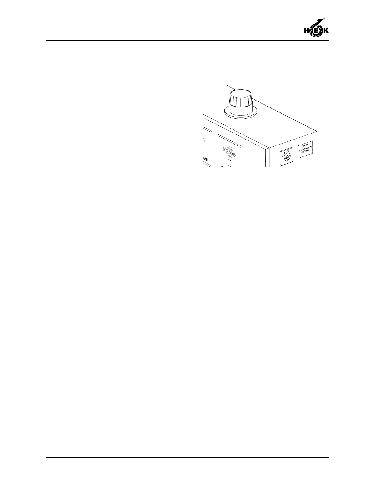
The MSHF mast climbing work platform is
provided with an eccentric overload
device. The eccentric overload device is
only active in a single-mast construction.
When the platform is eccentric overloaded
to 90%, the light on top of the control box
starts to burn.
When the platform is eccentric overloaded
to 100%, the light on top of the control box
will burn and a buzzer will sound. In this
situation the machine can not be operated.
When the cause of overload is removed
the eccentric overload device will be reset
automatically .
Fig.7-6 Signal light
Page 67
DISASSEMBLY AND TRANSPORT
8-1MSHF • 7295-026A
8. DISASSEMBLY AND TRANSPORT
Ensure that the maximum
loading allowed during assembly
is not exceeded.
In winds of strenghts above
6 Beaufort (12,5 m/s) (41 ft/s),
the machine may not be
disassembled.
1. Remove the mast guards.
2. Disassemble the mast elements
above the uppermost anchor. Before
loosening the uppermost anchor,
lower the disassembled elements to
the ground. Now disconnect the
uppermost anchor.
3. T ogether with the disassembly of the
mast, the anchor tubes, the anchors
and the cable guides must be
disassembled.
4. If a crane is available on the building
site, the mast can be more quickly
disassembled. As many as five mast
elements can be removed together
and lowered to the ground with the
crane. The mast elements can further
disassembled on the ground.
5. Repeat this procedure until the mast,
with the platform in its lowest
position, has been completely
disassembled.
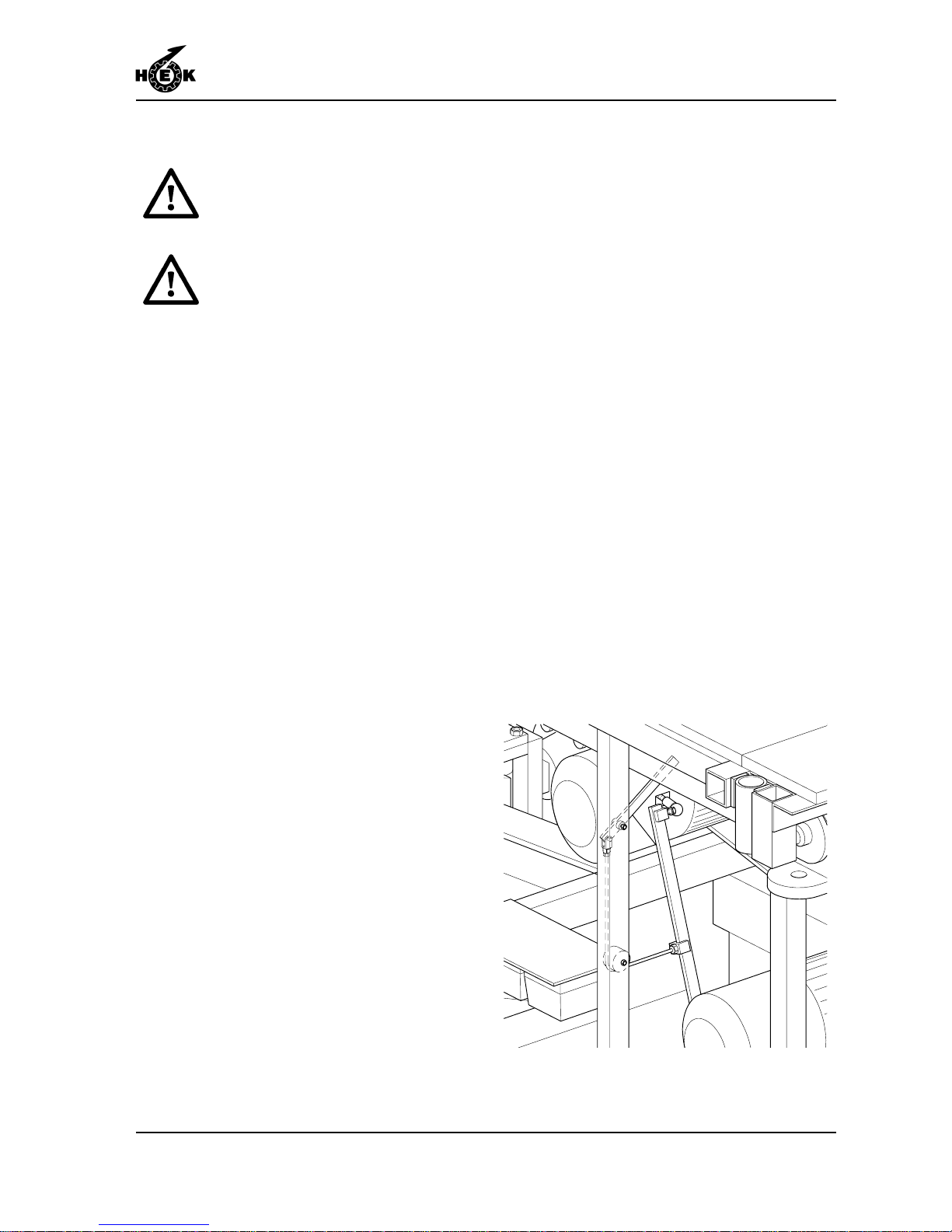
6. Release the brakes and allow the
platform to descend onto the buffers.
Fig.8-1 Drive unit brake release
Page 68
DISASSEMBLY AND TRANSPORT
8-2 MSHF • 7295-026A
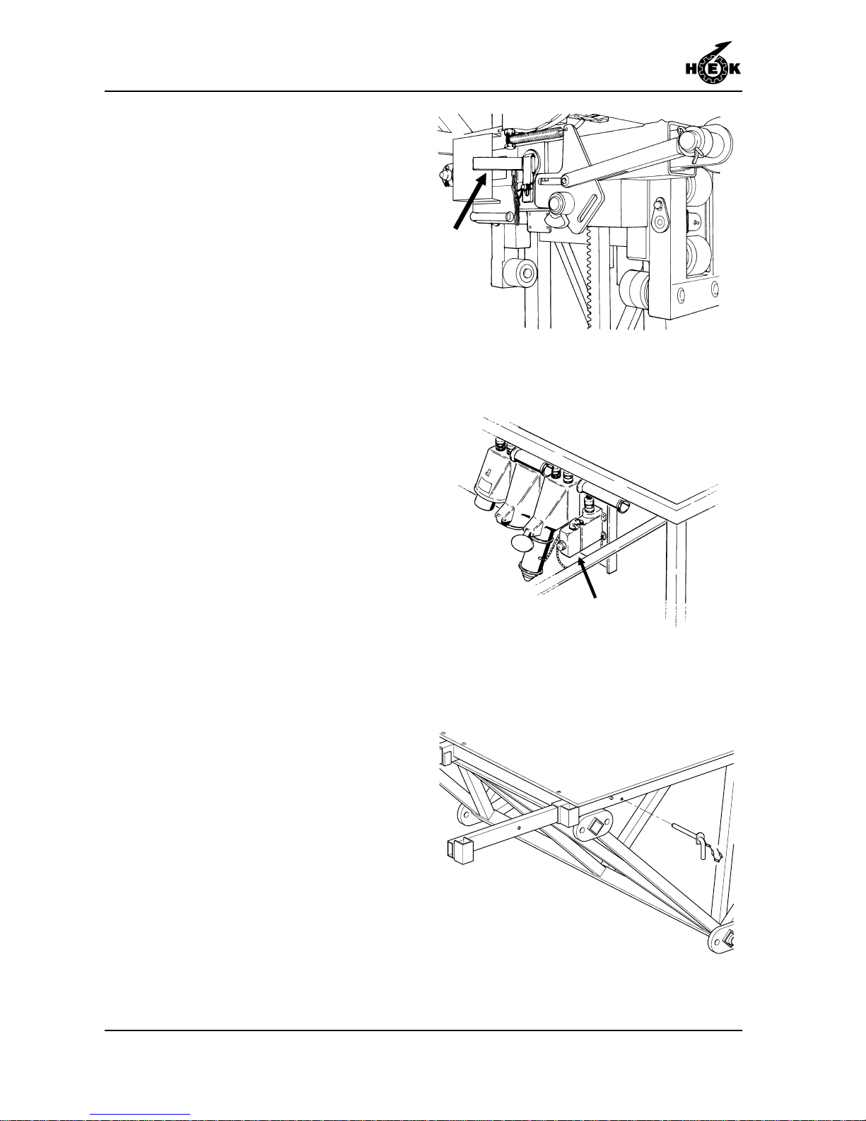
7. Insert the locking pins in the autolevel
devices and secure them.
8. Disconnect the electrical supplies
and replace the control cable dummy
plug (for a twin mast construction).
9. Raise the jacks and remove the
ground supports.
10. Remove the control box.
There are two possible ways to transport
the basic machine. This can be done with
or without the platform elements being
attached. The transport method depends
on the dimensions of the platform and the
widths and lengths of vehicles permitted by
national regulations.
If the basic machine is too large to be
transported in one piece, take the following
steps.
1 1. Disassemble the fences, the gates
and the gate posts.
12. Disassemble the platform
extensions. Slide in the outriggers
and secure them.
Fig.8-2 Autolevel locking locking pin
Fig.8-3 Control cable dummy plug
Fig.8-4 Securing outrigger
Page 69
DISASSEMBLY AND TRANSPORT
8-3MSHF • 7295-026A
13. Disassemble the platform elements.
During the disassembly of the
platform elements, care must be
taken that the machine remains in
balance. Support the platform if
necessary .
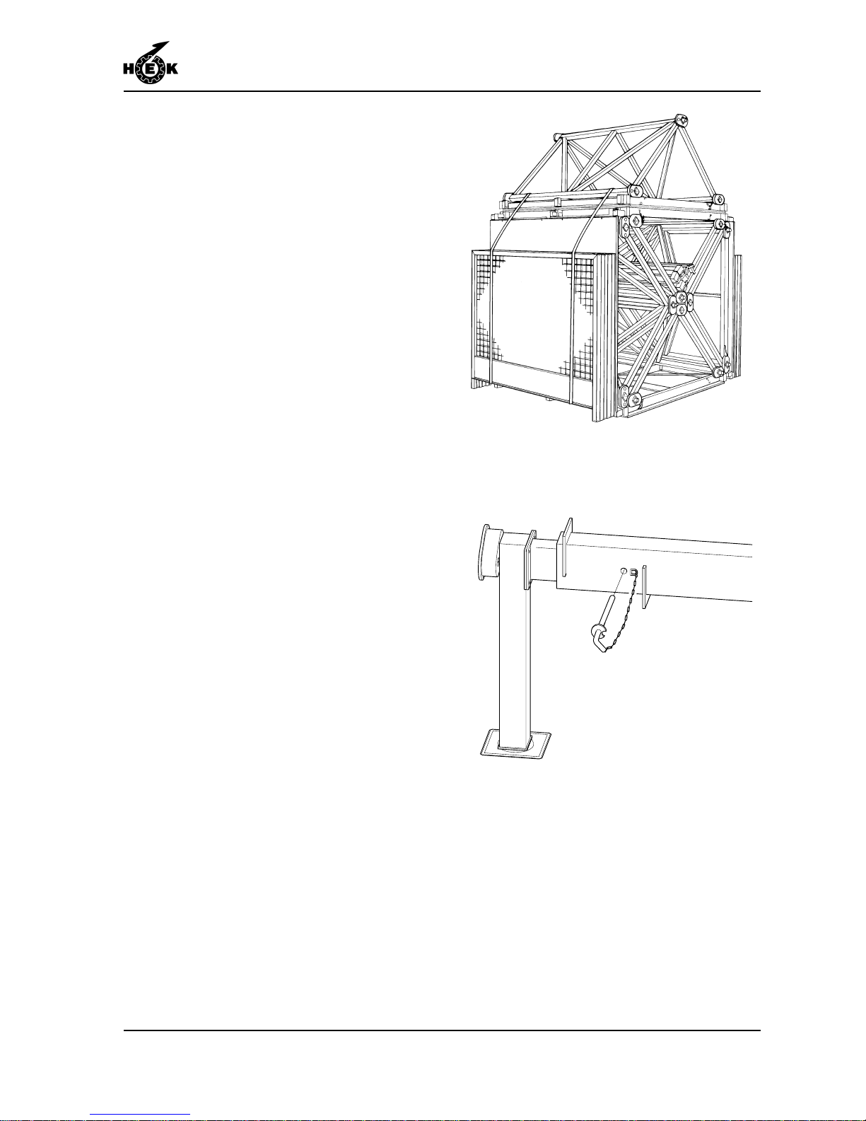
14. The platform elements can be
packed in bundles of five.
15. Slide in the outriggers of the chassis
and secure them.
Fig.8-5 Bundle platform elements
Fig.8-6 Locking pin outrigger
Page 70

DISASSEMBLY AND TRANSPORT
8-4 MSHF • 7295-026A
Page 71

MAINTENANCE
9-1MSHF • 7295-026A
9. MAINTENANCE
9.1 General
The simple robust construction of the machine ensures that maintenance can be kept to a
minimum. Sensible use of the machine, regular checks for correct functioning and regular
cleaning will result in a minimum requirement for maintenance. This will guarantee a long
working life for the mast climbing work platform.
Parts must comply with to the technical specification of Hek Manufacturing b.v .!
Use only original parts of Hek Manufacturing b.v .
9.2 Maintenance intervals
The following maintenance activities are essential:
A. Weekly maintenance
- Grease the rack and pinion. If these are heavily contaminated with sand or grit they must
be cleaned first.
Specification for grease:
- HEK-rack and pinion grease
- Shell Rhodina 2
- Clean the platform and the drive unit.
- Carry out the checks detailed in section 7.2.
- Visually inspect the rack and pinion drive.
B. Monthly maintenance
- Inspect the guide rollers (visual inspection of security devices, gaskets and bearings).
- Check that all mast bolts are tightened with the correct torque.
- Check that all anchors are secure and re-secure any loose parts.
- Check the functioning of all limit switches.
- Grease the jacks and the king pins of the chassis.
- Grease the drive unit pressure rollers.
- Perform the activities listed at A.
Page 72

MAINTENANCE
9-2 MSHF • 7295-026A
C. Quarterly maintenance
- Check the motor brake (see section 9.4.2)
- Check the play in the guide rollers.
- Check the rack and pinion (visual).
- Perform the activities listed at A and B.
- For a mast climbing work platform with twin masts, check the operation of the autolevel
device (see section 9.3).
D. Annual maintenance
- Check that the platform elements are tightened with the correct torque.
- Check the rack fixing bolts.
- General inspection of paintwork, corrosion and welds.
- Perform the activities listed at A, B, and C.
- Eccentric overload mechanism
- remove the eccentric mechanism.
- clean the eccentric mechanism.
- grease the moving parts and reinstall the mechanism.
- Check all welds of the mast climbing work platform.
E. Biennial maintenance
- Change the oil in the drive unit reduction gearbox. Lubricant specification for STEPHAN
motors:
According to DIN 51502, kinetic viscosity acc. to DIN 51562 of approx. 220 mm²/sec.
- Aral Degol BMB
- Shell Macoma W 71
- Esso V artan 220
- Re-grease the bearing of the reduction gearboxes.
- Perform the activities listed at A, B, C and D.
F . Maintenance during storage of the machine
- Inspect the machine in its entirety.
- Check all vital parts and replace any which have become damaged.
- Clean and grease the rack and pinion drive.
- Inspect the mast elements (with the racks) and check that all separate connection
pieces are in order .
- Check the lowest mast bolts for corrosion and replace them if necessary.
- Cover the basic machine with a tarpaulin; in every case, cover the control boxes and the
limit switches.
- Screw out the jack of the chassis so that it does not rest on its wheels.
- For long-term storage, consult your dealer.
Page 73

MAINTENANCE
9-3MSHF • 7295-026A
9.3 Autolevel mechanism check
1. Raise the platform by three metres.
2. Operate the brake release
mechanism on one drive unit. The
autolevel safety mechanism must
now operate.
3. Set the platform back in the horizontal
position with the "UP" push-button.
4. Repeat the previous step for the
other unit.
5. If the autolevel safety mechanism
does not function correctly , the mast
climbing work platform must not be
used! Consult your service engineer .
9.4 The motor brake
The motor has a built-in electromagnetic
brake. This brake functions according to
the "normally ON" principle, that is, when
the motor has no power supply the brake is
active and the motor shaft will be braked.
(n = 0 rev ./min).
The braking effect is achieved by friction
between several discs and the brake must
be used "dry" (not greased).
Fig.9-1 Drive unit brake release
Page 74
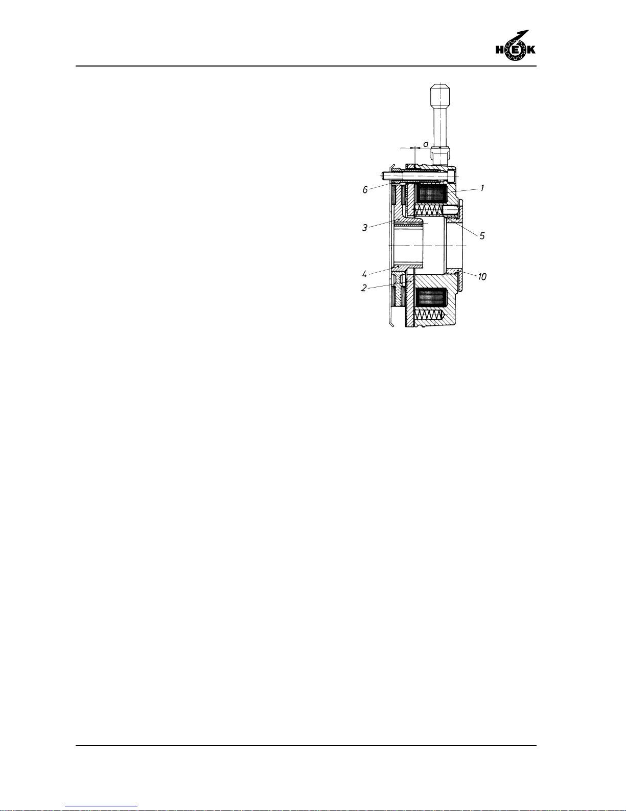
MAINTENANCE
9-4 MSHF • 7295-026A
9.4.1Operation
The brake mechanism has a metal rotor
(3) with friction material on both sides.
Four pressure springs (5) in the stator
exert an axial force on an anchor plate (2).
This anchor plate is pressed by the spring
force against rotor. The rotor is mounted on
the motor shaft in such a way that it can
slide in an axial direction along the shaft.
Because the anchor plate presses against
the rotor, the rotor is pressed against the
friction plate (6). The contact between the
friction material on either side of the rotor,
the anchor plate and the friction plate
results in the required braking effect.
The stator has a built-in braking coil (1)
which produces a strong magnetic field
when a DC current is applied to it.
When the brake is to be released, a
current is made to flow through the braking
coil. The resulting magnetic field "pulls" the
anchor disc toward the stator , thus
releasing the brake.
It is also possible to release the brake
manually . If the manual release lever is
pressed in the direction indicated by the
arrow on the cover, the anchor plate is
moved against the spring pressure with the
aid of two ball bolts, so that it is pressed
towards the stator, releasing the brake.
Fig.9-2 Motorbrake
Page 75
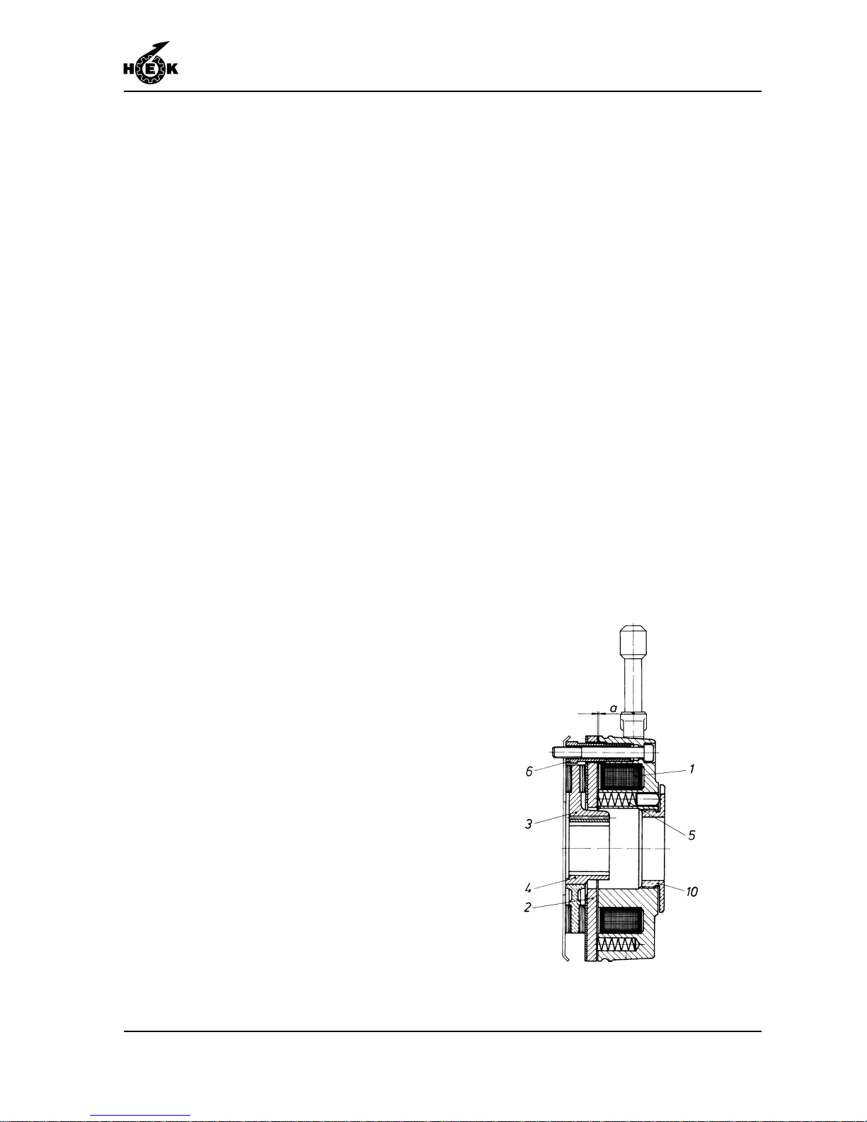
MAINTENANCE
9-5MSHF • 7295-026A
9.4.2Maintenance
In normal use the motor brake is more or
less maintenance free. However, after
frequent raising and lowering of the
platform it may be necessary to adjust the
air gap between the anchor disk and the
stator, and if necessary , to replace the
rotor.
In order to check the condition of the brake,
the width of the air gap "a" and the
thickness of the friction material on the
rotor must be measured every three
months.
The air gap "a" is adjusted by the
manufacturer to 0.3 mm / 0.012 in and
must never be more than 0.9 mm /
0.035 in. The total thickness of the rotor
(including the friction material) must not be
less than 9.5 mm / 0.37 in.
T o check:
1. Switch off the mast climbing work
platform at the main switch and
secure the switch with the padlock.
2. Remove the brake release
mechanism using an open ended
spanner.
3. Remove the fan cover from the motor.
4. Use a feeler gauge to measure the
width of the air gap "a" close to the
three hollow adjusting bolts (6).
5. Remove the rubber dust ring and use
a vernier calliper gauge to measure
the thickness of the rotor. Replace the
rotor if the thickness is 9.5 mm / 0.37
in or less.
Fig.9-3 Motorbrake
Page 76
MAINTENANCE
9-6 MSHF • 7295-026A
6. Adjust the width of the air gap "a" as
follows:
- Use an open-ended spanner to
turn the three hollow adjusting bolts
(6) further into the stator. Ensure
that these bolts are all screwed
into the stator by the same amount.
- Use a feeler gauge to measure the
width of the air gap "a" close to
each of adjusting bolts and turn the
bolts until the gap by each bolt is
just 0.3 mm / 0.012 in wide.
The adjustment of the hand
release may not be changed, not
even when air gap "a" is
readjusted, as security can be
adversely affected.
7. Mount the rubber dustring, the fan
cover and the brake lever.
Page 77
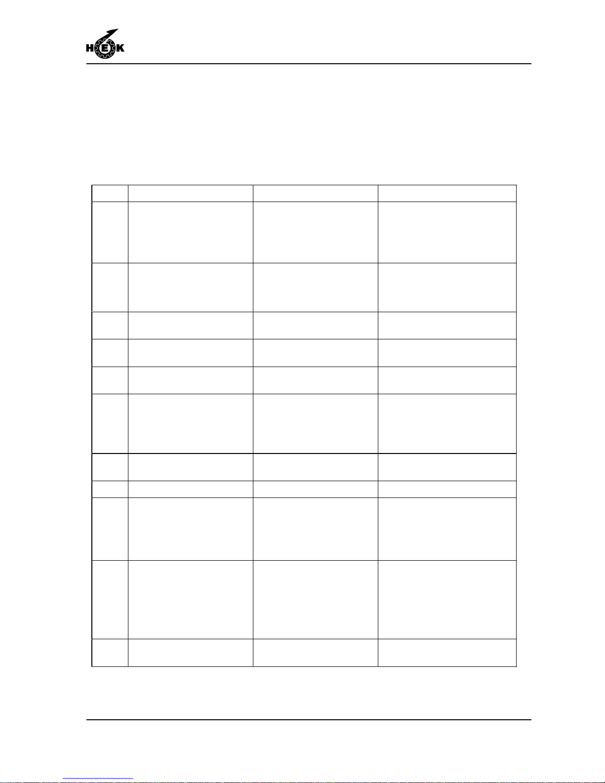
MALFUNCTION ANALYSIS
10-1MSHF • 7295-026A
10. MALFUNCTION ANALYSIS
The control box on the platform has an "information panel". This "information panel"
consists of a display on which fault codes appear in the event of a malfunction. An
explanatory list of fault codes is attached to the control box as an aid to rapid and efficient
fault repair. The following table gives an indication of the methods to be employed in the
event of a malfunction.
In all cases not covered by the above malfunction tables an electrician must be
consulted.
Code Description Malfunction Solution
01 Motor M1 & M2 thermal
overload
- Platform loading too high
- Voltage too low
- Motor stalled
- Reduce loading
- Consult an electrician
- Consult an electrician
02 Phaseguard relay - Main switch incorrect
position
- Set main switch in the other
position; if the malfunctio n is
not corrected, consult an
electrician.
03 Emergency stop
pushbutton
- Pushbutton depressed - Rotate pushbutton to release
04 Eccentric overload - Platform eccentriacally
overloaded
- Reduce loading
05 Limiting switch bottom - The machine has run too
far downward
- Consult an electrician
06 Motor control unit - Motor control malfunction - Switch off the main switch for
30 seconds and then on
again; if the malfunction is not
corrected, consult an
electrician
07 Limiting switch top - The machine has run too
far upwards
- Consult an electrician
08 Fall safe brake/other - Fall safe brake in operation - Consult an engineer
09 Gate/other - Gate is open
- Connector not in socket
- Switch defective or
"sticking"
- Close the gate
- Plug connector into socket
- Check the switch
12 Mast detection sensor - Machine run too far during
assembly phase
- Switch defective
- Move the machine downward;
if the malfunction is not
corrected, consult an
electrician
14 L/R malfunction - Fuse F104 deactivated - Set machines Left and Right,
activate fuse F104
Page 78
MALFUNCTION ANALYSIS
10-2 MSHF • 7295-026A
In all cases not covered by the above malfunction tables an electrician must be
consulted.
No power supply
- Defective fuses in building site supply
- Damaged cable
- Motor safety relais switched off
- Main switch defective
Voltage too low
- Incorrect cable type
- Cable is too long
Motor does not run
42 Vac control voltage
not present
- Automatic fuses operated
Voltage present but
platform cannot be raised or
lowered
Relays K102 en K103 are
energized but platform
does not move up or
down
- Motor brake locked
- Adjust brake
Brake distance too long
- Wrong adjusting parralel movement
protection
- Adjust brake
The platform decends
erratically
- Minimum mast distance too little
Other malfunctions
The platform does not
develop sufficient power
- Inform your technical service or dealer
Page 79

MACHINE DISPOSAL
11-1MSHF • 7295-026A
11. MACHINE DISPOSAL
General
After a number of years of reliable service the life of every machine inevitably comes to an
end. The machine must then be disposed of in an as environmentally friendly manner as
possible.
Amongst others, the following possibilities present themselves:
- Part exchange for a new machine.
- Disposal by a recycling facility.
- Demolition.
Discarding the machine
- Drain the oil out of the reduction gearbox and dispose of this via an authorized facility.
- Remove any usable parts.
- Dispose of the remainder via waste disposal facility.
Page 80

MACHINE DISPOSAL
11-2 MSHF • 7295-026A
Page 81

LIST OF KEYWORDS
12-1MSHF • 7295-026A
12. LIST OF KEYWORDS
A
A-symmetrical configurations 1- 8
Adjustment switch EMOS 5-2
Air gap 9- 5
Anchor forces 1-14, 6-17
Anchor ramp 6-19
Anchoring 6-17
Assembly and anchoring 6-1
Autolevel mechanism 9 -3
Autolevel switches 6-23
B
Blue control light 5-2
Brake test 7-3
Buffer 6-15
Built-in and additional safety features 3-3
C
Chassis drive unit 4-3
Concrete foundation 6- 3
Config panel 5-2
Control cable 6-10, 6-13
Control components 5- 1
Crane 2-1
D
Definition left and right 6-1
Dimensions X
Disassembly and transport 8- 1
Distance to the facade 6- 4
Drive unit 2-1
E
EC Declaration of Conformity VIII
Eccentric overload device 7- 6
Electrical installation 1-5
Electrical power supply 6 - 2
Emergency push-button 5- 2
Emergency situation 7- 4
EMOS system 6-24
F
Fencing 6-4, 6-6, 6-7, 6-9, 6-12, 6-20
Foreword V
G
Gate safety switch 6-6, 6-7, 6-10, 6-12
Ground pressure 6- 3
Ground support 6- 3
H
Hard road surface 6-3
Horn 5-2
I
Info panel 5-2
K
Keyswitch adjustment left/right 5 - 2
Keyswitch buffer 5-2
L
Lightning protection 6-24
Loaded and unloaded 4 -1
Locking pin 6-5, 6-7, 6-8, 6-11
Lower striker plate 6-5, 6-7, 6-8, 6-11, 6-22
M
Machine disposal 11 -1
Main switch 5- 2
Maintenance 9-1
Maintenance intervals 9- 1
Malfunction analysis 10-1
Mast 6-14
Mast cover 6-16
Motor brake 9- 3
O
Operation 7-1
Outriggers 1-10
P
Parts 9-1
Platform control box 5- 2
platform width 6-19
Positioning the mast climbing work platform 6-4
Power supply socket chassis 5-1
Power supply socket drive unit 5- 1
Proximity switch 6-15
Push button DOWN 5-2
Push button UP 5- 2
R
Reaction force 7- 1
Repositioning on the building site 4- 2
Repositioning with a crane 4- 4
Page 82

LIST OF KEYWORDS
12-2 MSHF • 7295-026A
S
Safety 3-1
Safety after use 3-3
Safety in use 3- 1
Safety prior to use 3- 1
Scaffold coupling 1-14
Setting the machine left or right 6-21
Signal light 5- 2
Special situations 1-1
Symbols IX
Symmetrical platform construction 1- 8
T
Testing 7-3
T op element 6-16
Transport 4 -1
Transport weight 4-4
Page 83

APPENDICES
1MSHF • 7295-026A
Page 84

APPENDICES
2 MSHF • 7295-026A
 Loading...