

Page 1

Network Video Recor
der
USER MANUAL v1.1
Page 2

Page 3
To prevent re or shock hazard, do not expose the unit to rain o
r moisture.
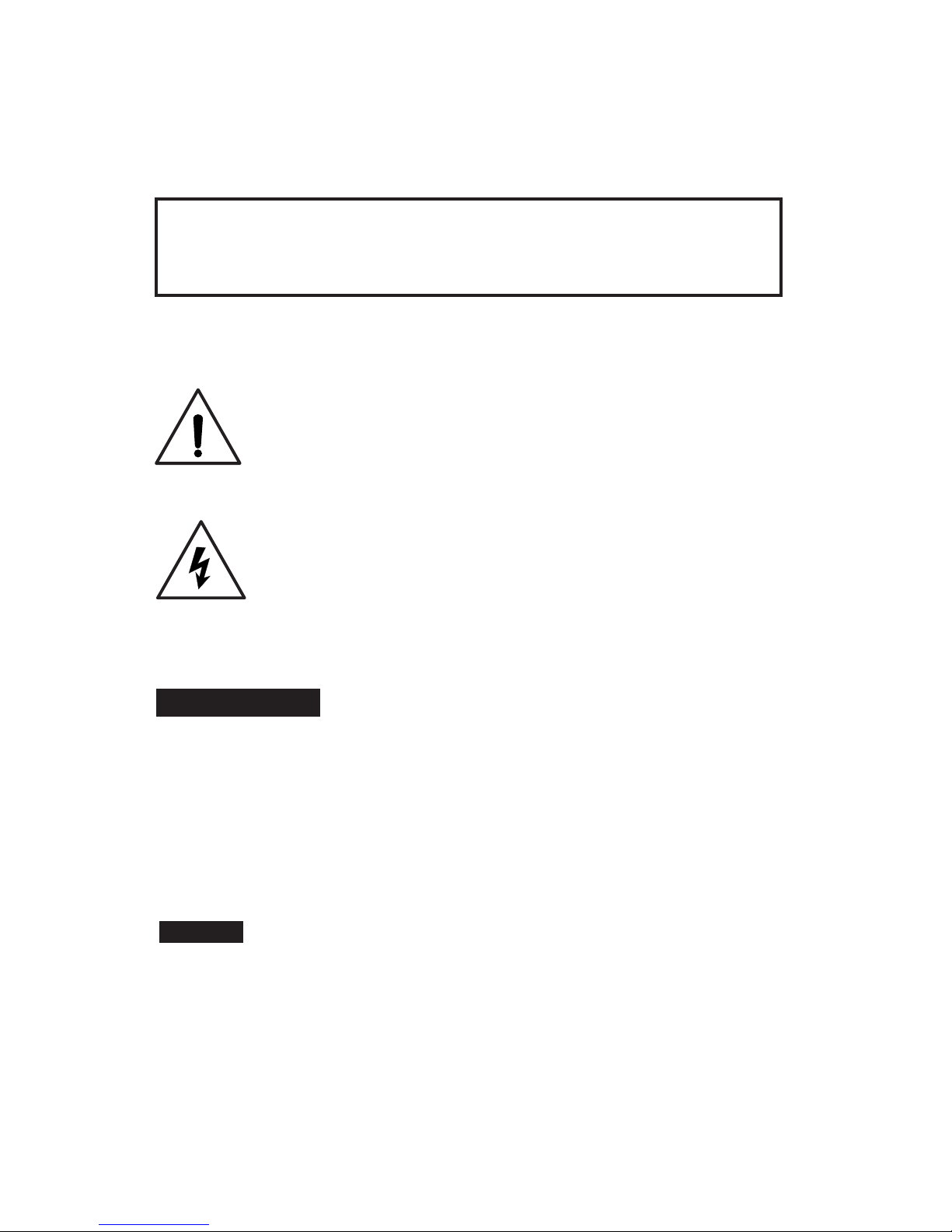
The symbol is intended to alert the user to the presence of important
operating and maintenance(servicing) instructions in the literature
accompanying the appliance.
The symbol is intended to alert the user to the presence of uninsulated
“dangerous voltage” within the product’s enclosure that may be of sufcient,
magnitude to constitute a risk of electric shock to persons.
SA1966
SA1965
CAUTION
TO
PREVENT ELECTRIC SHOCKS AND REDUCE RISK OF FIRE HAZARDS, DO NOT USE
OTHER THAN SPECIFIED POWER SOURCE.
WARNING
FCC INFORMATION
This
equipment has been tested and found to comply with the limits for a Class A digital
device. Pursuant to part 15 of the FCC rules, these limits are designed to provide reasonable
protection against harmful interference when the equipment is operated in a commercial
environment. This equipment generates, uses, and can radiate radio frequency energy
and if not installed and used in accordance with the instruction manual, may cause harmful
interference to radio communications. Operation of this equipment in a residential area is
likely to cause harmful interference in which case the user will be required to correct the
interference at his own expense.
Any changes of modications in construction of this device which are not expressly approved
by the party responsible for compliance could void the user’s authority to operate the
equipment.
Page 4

Page 5

目 录
CHAPTER 1 Introduction ............................................................................................................... 1
1.1 Pr
ecautions
....
...............................................................................................................
1
1.2 Product Appearance
....
.............................................................................................
1
1.2.1 Front P
anel
..
......................................................................................................
1
1.2.2 Rear P
anel
....
.....................................................................................................
2
1.3 Specification
.....
............................................................................................................
4
CHAPTER 2 Syst
em User Manual
.................................................................................................5
2.1 Syst
em Application
....
................................................................................................
5
2.1.1 Star
ting up the NVR
....
...................................................................................
5
2.1.2 The main inter
face
....
......................................................................................
5
2.1.3 Playback ..
............................................................................................................
7
2.2 Paramet
ers Configuration
....
...................................................................................
8
2.2.1 Video ....
..............................................................................................................
8
2.2.2 Scheduled Record ....
.......................................................................................
9
2.2.3 Users ....
..............................................................................................................
10
2.2.4 Network ....
........................................................................................................
11
2.2.5 Reboot
..
.............................................................................................................
12
2.2.6 St
orage
.................
...................
....
.....................................................................
12
2.2.7 Document management
..
...........................................................................
13
2.2.8 Adjustment ....
..................................................................................................
14
2.2.9 Motion Detection ....
......................................................................................
15
2.2.10 PTZ ....
...............................................................................................................
16
2.2.11 Decoder ..
........................................................................................................
17
2.2.12 Alarm ..
.............................................................................................................
18
2.3 Remot
e view
....
.........................................................................................................
20
2.3.1 Network S
tructure
..
.......................................................................................
20
2.3.2 Network Setting ..
...........................................................................................
20
2.3.3 IE Remot
e Monitoring System
....
..............................................................
21
2.3.4 Central Monitoring S
ystem
..
.....................................................................
23
Page 6

2.3.4.1 User Instruction ....
............................................................................
23
2.3.4.2 Local Settings .....
..............................................................................
23
2.3.4.3 Remot
e Settings
.....
.........................................................................
25
CHAPTER 3 Syst
em Installation
................................................................................................28
Page 7
-1-
User manual of NVR
CHAPTER 1 Introduction
1.1 Precautions
1.
Before starting NVR, make sure that the voltage of the extra power supply is
the same as the NVR's requirement (110V/220V), and the ground connection is
working properly.
2. Power off the NVR before connecting or disconnecting accessories and
peripherals.
1.2 Product Appearance
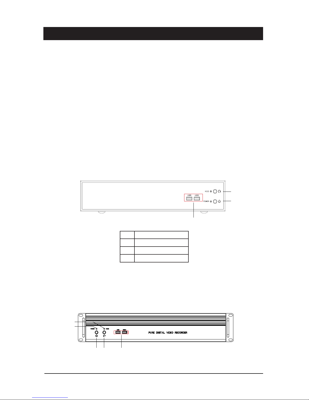
1.2.1 Front P
anel
1.
Type A
(4/9/16-ch);
T
ype G
(16-ch, 4 SATA)
2.
Type G
(16-ch, 8 SATA)
No. Name
1 Pow
er On/Off
2 Reboot
3 USB Interfaces
1
2
3 4 5
3
2
1
PURE DIGITAL VIDEO REC
ORDER
Page 8
-2-
User manual of NVR
1.2.2 Rear P
anel
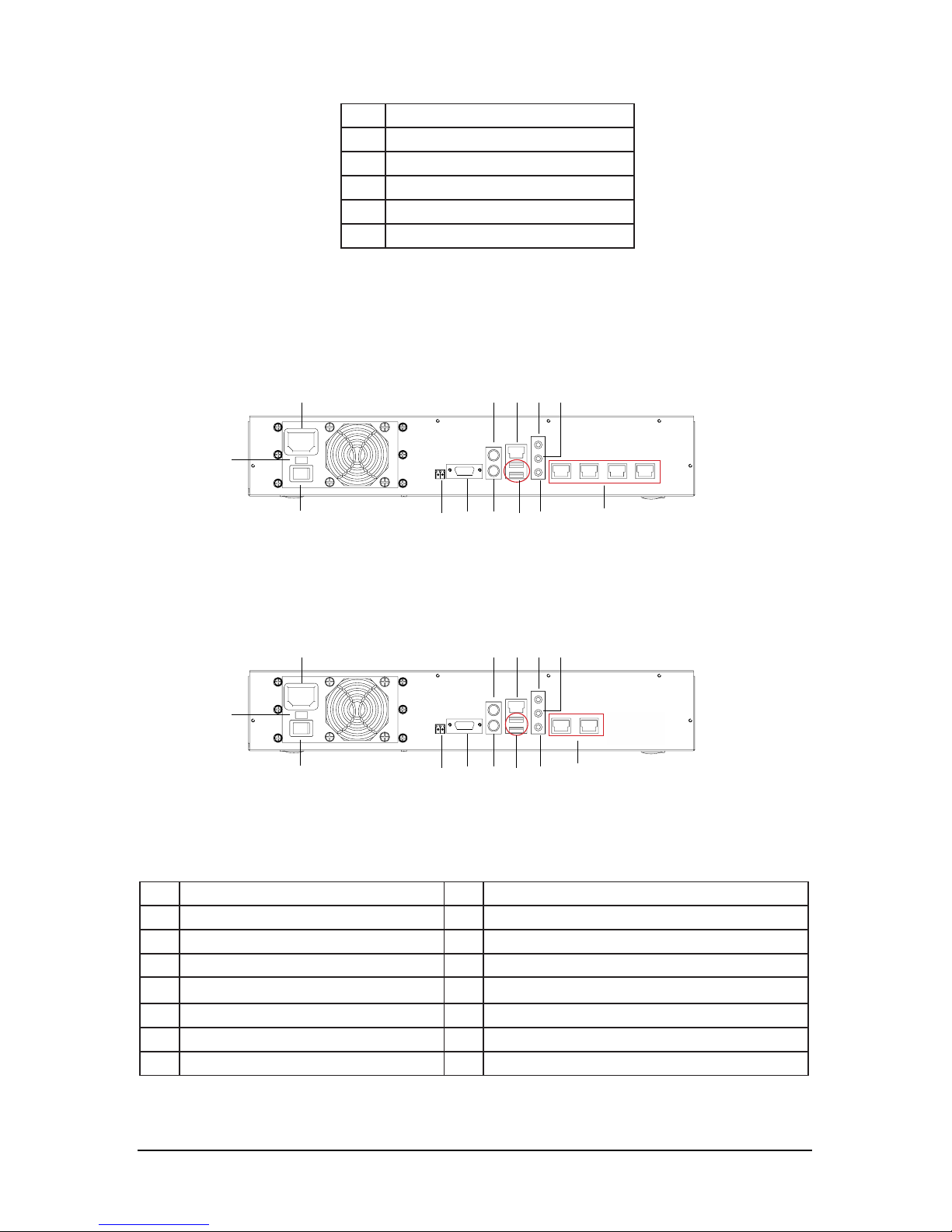
1. (1)
Type A
(4-ch)
(2)
T
ype A
(9/16-ch)
No. Name No. Name
1 AC 220V/110V P
ower Input 8 USB Interfaces
2 220V/110V Transfer Switch 9 LAN 1 (For LAN or WAN Connection)
3 Power On/Off 10 Audio In
4 RS485 Interface 11 Audio Out
5 VGA Output 12 Line In
6 PS/2 Mouse Interface 13 LAN
7 PS/2 Keyboard Interface
No. Name
1 P
ow
er Indicator LED
2 HDD Indicator LED
3 Power On/Off
4 Reboot
5 USB Interfaces
3 4 5 7 8 10 13
1 6 9 12 11
2
3 4 5 7 8 10 13
1 6 9 12 11
2
Page 9
-3-
User manual of NVR
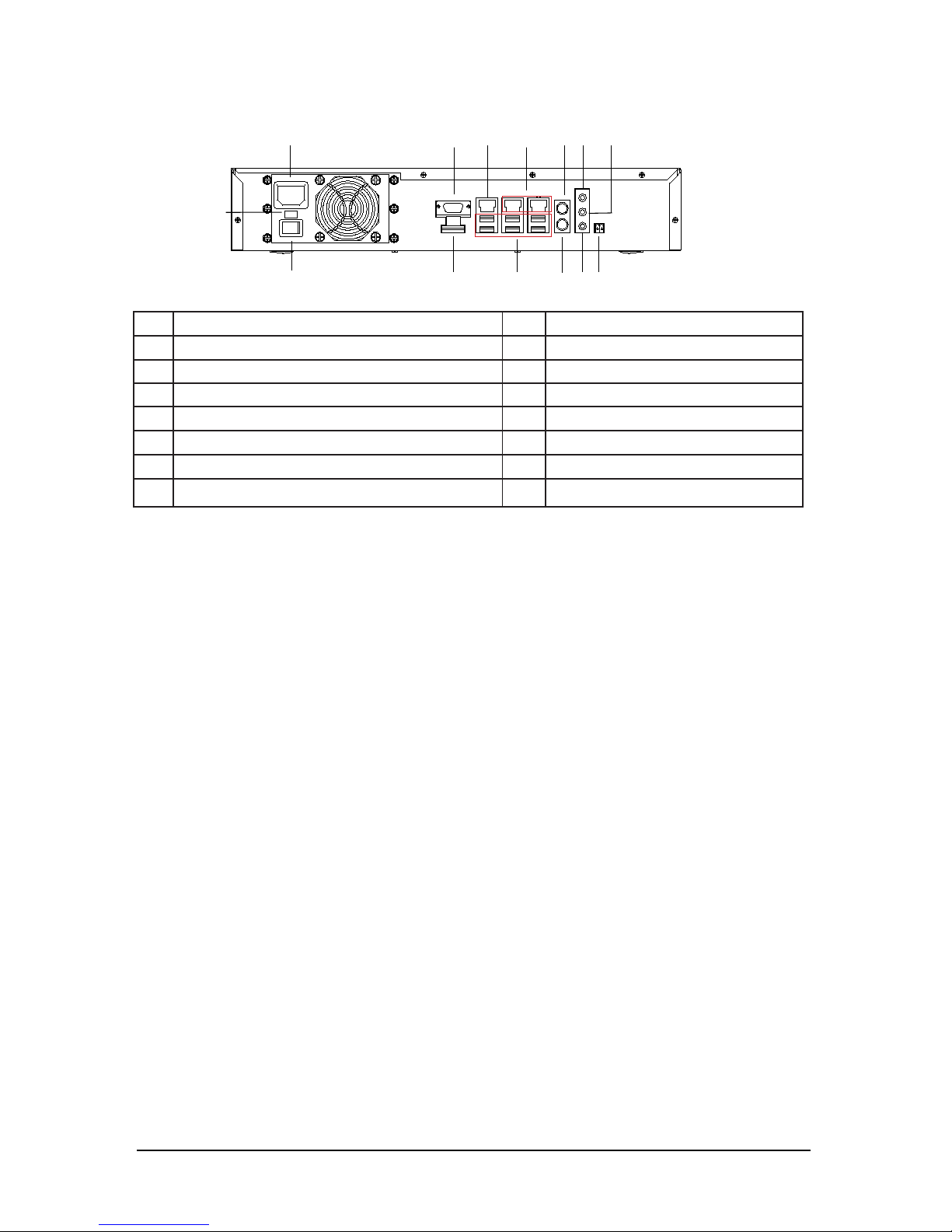
2.
Type G
(16-ch)
No. Name No. Name
1 AC 220V/110V P
ower Input 8 USB Interfaces
2 220V/110V Transfer Switch 9 PS/2 Keyboard Interface
3 Power On/Off 10 PS/2 Mouse Interface
4 VGA Output 11 Line In
5 HDMI Output 12 Audio Out
6 LAN 1 (For LAN or WAN Connection) 13 Audio In
7 LAN2/LAN3 14 RS 485 Interface
Notes:
1.Pictur
es are for reference only, specifications are subject to the phisycal product.
2. LAN 1
for LAN or WAN connection
, and the other netw
ork int
erfaces are for IP cameras.
1 4 6 7 10 11 12
2
3
5
8 9
13
14
Page 10

-4-
User manual of NVR
1.3 Specification
Model No.
Type A Type G
Video Input 4-ch 9/16-ch 16-ch
Video compression MPEG-4/H.264
R
ecord Resolution 1280x720 1280x720/1920x1080
Preview Resolution 1280x720/432x240 1920x1080/1280x720/432x240
Video Output VGA VGA/HDMI
Mouse interface 1 PS/2
Keyboard interface 1 PS/2
RS-485 Interface 1
Audio Interface MIC IN/SPEAKER OUT/ LINE IN
Network Interface
4 R
J45 10M/100Mbps
1 R
J45 1000Mbps
2 RJ45 10M/100Mbps
1 RJ45 1000Mbps
3 RJ45 1000Mbps
POE suppor
t without
USB Int
erface 4 8
Interface Type 2 SATA 3 SATA 4 SATA 8 SATA
Power Supply 220V 50Hz/ 110V 60Hz
Consumption
(without HDD)
≤ 50W ≤ 70W
Wo
rking Temperature
-10℃ ~+60℃
W
orking Humidity 10%~90%
Operating System Linux
Page 11
-5-
User manual of NVR
CHAPTER 2 Syst
em User Manual
Different
models of NVR are functionally similar,we take
Type G
as an example to
introduce function in detail.
2.1 Syst
em Application
2.1.1 S
tar
ting up the NVR
Pre
ss the
Power
button on the front panel. The Power indicator LED turn green
indicating that the NVR begins to start up. After successfully starting up, it come
into the main interface.
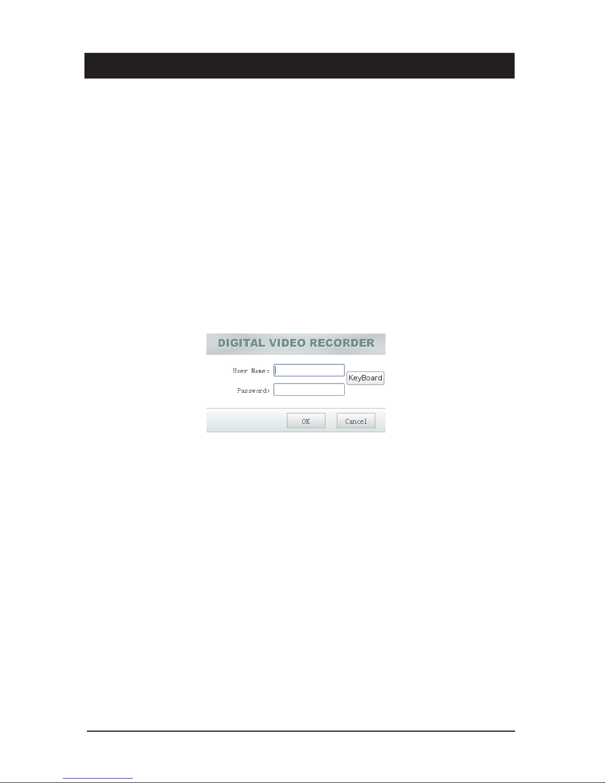
Click
lock
botton to enter login window.By default, the username and password of
administrator are empty, press ok button directly. To change username and
password, Please refer to
Users
in
Config
.
Notes:You could use on-screen keyboard by clicking the
keyboard
button.
2.1.2 The main inter
face
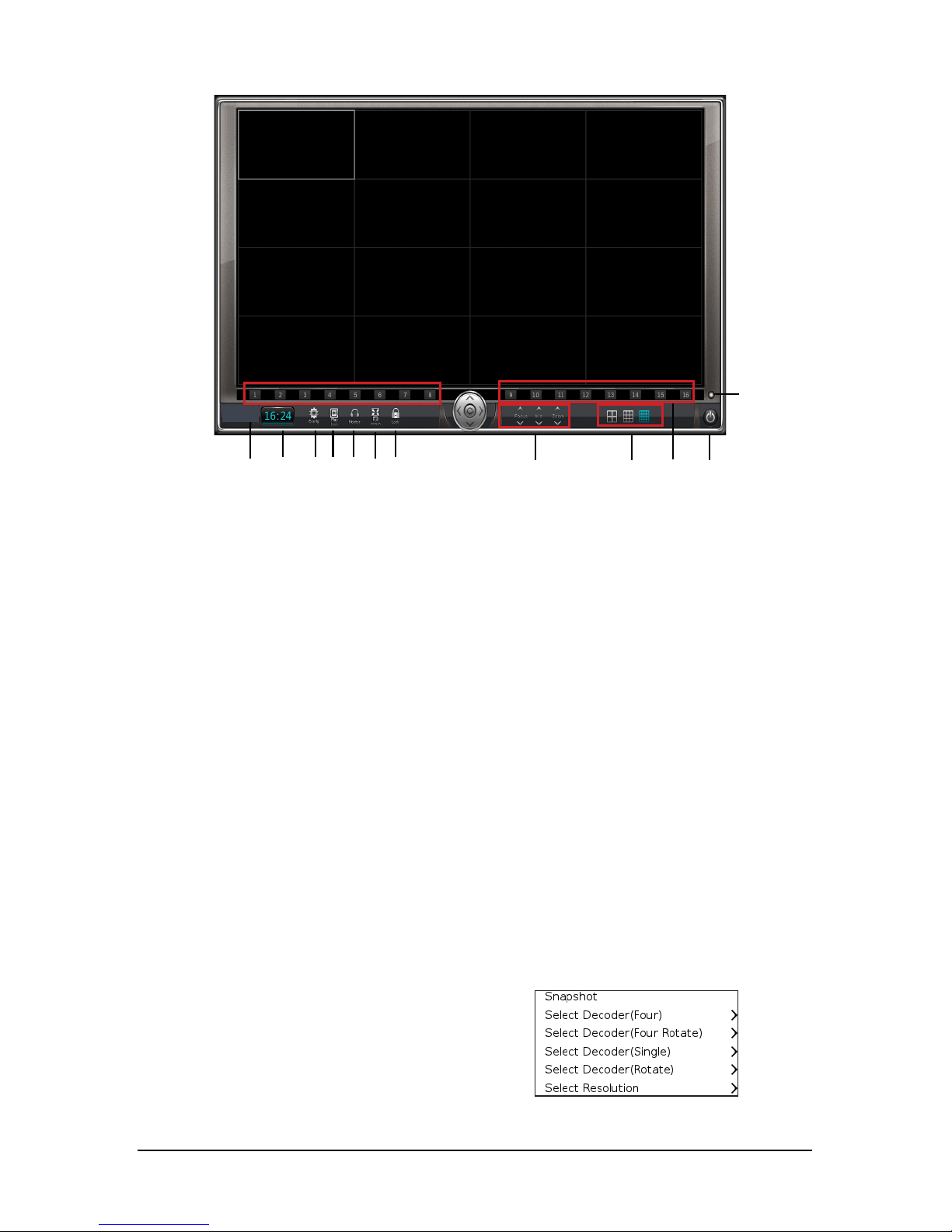
Syst
em Login interface is shown as following.
1-System Time
2-Config
Click to set up parameters.
3-Playback
Click to enter the playback Interface.
4-Monitor
Audio on.
5-Full Screen
Click to take you to full screen. To exit full screen mode, right click over the screen
then check
Backward
.
6-Lock/Unlock
Lock or unlock the system. Any click on the screen is invalid after locking the
Page 12
-6-
User manual of NVR
system. It is r
equired username and password to unlock the system.
7-PTZ Control
Click Up,Down,Left and right arrows to control PTZ rotating.
8-Screen Mode
Support 1/4/9/16 screen division.
9-Recording Status
Different background color of channel icon stands for different recording status,
Blue for recording and grey for out of recording. You can click channel ID to control
recording status when recording mode is setted "No Record" in
Scheuduled
Record
.
10-EXit
Click to shutdown or reboot the NVR.
11-ALL
Click to start or stop recording of all channels.
Menu of the main interface:
Right click over the screen on the main interface to get the menu as follow:
• Snapshot
click to take a snapshot.
• Select Decoder
Please refer to 2.2.11
Decoder
.
• Select Resolution
Click to select the proper resolution.
9 1 2 3 4 5 6 7 8 9 10
11
Page 13
-7-
User manual of NVR
2.1.3 Playb
ack
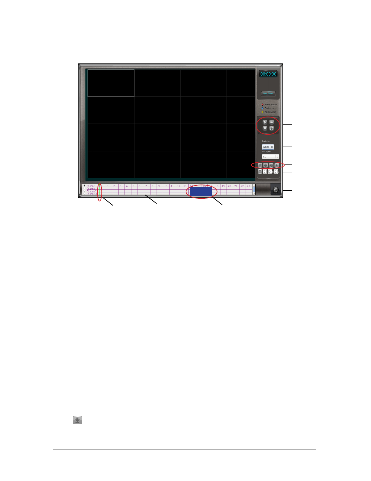
Click playback butt
on to enter the playback interface.
5
6
7
8
9
10
4
1 2
3
1-Progr
ess cursor
Move the cursor to control playing progress.
2-Playback coordinate
The abscissa represents the time of playing, and the ordinate the channel of
camera. Choose the channel you that want to play by checking the corresponding
channel number.
3-Recording Progress bar
Blue bar means continuous record, red bar means motion record.
4-Date select
Click to select date of record to playback. Dates marked in color means there is
record(files) in the day.
5-Play/Stop, Single frame play, Light, Monitor
6-Display time font in white or black optional.
7-Play speed
Support x1, x2, x4, x1/2, x1/4 and fast browse(playback 1hour file in 1minute).
8-Zoom,Print,Snapshot,Backup
Steps for backup:
1.click
to access Backup window;
2. choose the camera y
ou want to backup;
3. Enter begin time and end time of the record;
Page 14
-8-
User manual of NVR
4. choose
the format of backup files ( “dvr”format files can be played with DVR
player, “exe” format files can be played directly, just double click the file);
5. choose the path to backup .
9-Time positioned play
To enter a specific time for playback.
10-EXIT
2.2 Paramet
ers
Configuration
2.2.1 Video
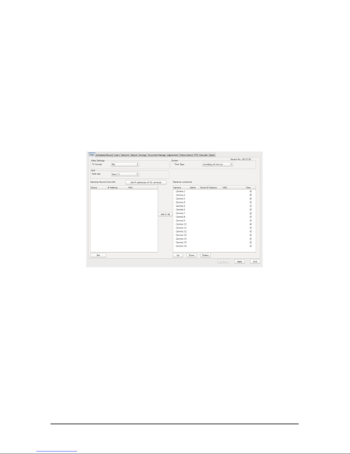
Click
Config
button on the main int
erface, enter into the
Video
interface as shown.
• TV Format
PAL/NTSC
• Font Size
Click dropdown list to select the proper font size.
•
Time type
Select the time display format.
• Get IP addresses of HD cameras
Click to search cameras in the LAN which will be listed on the leftside box.
• Device
Show the network card to which IP camera connects. There are eth0,eth1 and eth2.
• IP Address
Show IP addresses of cameras searched in the LAN.
• MAC
Show MAC addresses of cameras searched in the LAN.
• Set
Page 15
-9-
User manual of NVR
Select the camera you want t
o change IP on the left list. Click
Set
and input new IP.
•
Add to list
Choose
the IP address on the left list and then click
Add to list
to add the camera
onto the NVR host.
• Name
Double click camera's Name on the right list and input new name for camera.
• View
Check the box, the video will be shown on the main interface.
• up/down
To adjust cameras' order. Choose the camera, click up(down) to adjust it's order.
• Delete
Choose the camera on the right list, click
Delete
to disconnect it.
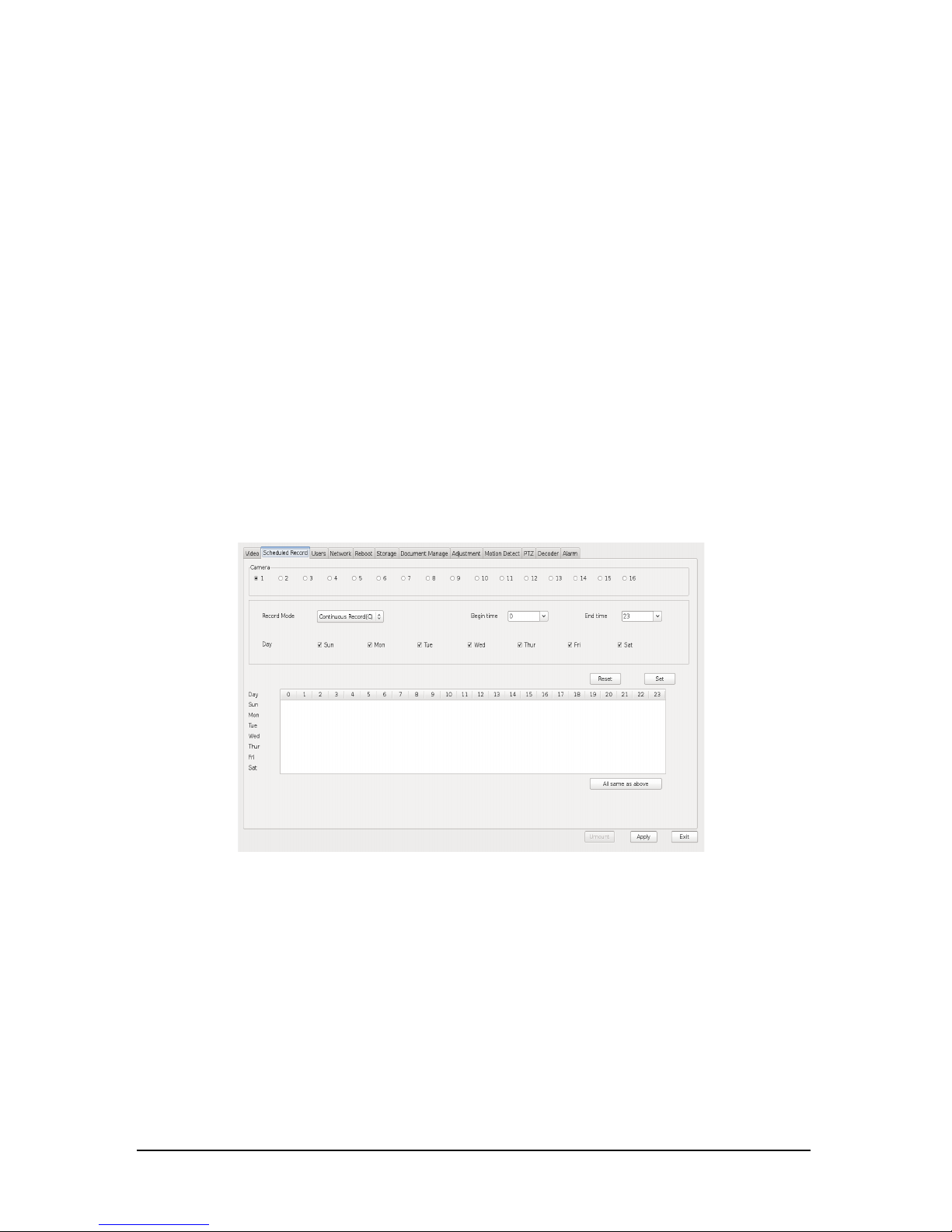
2.2.2 Scheduled Recor
d
Click
config
button on the main interface, to access the
Scheduled Record
interface as shown.
•Camera
Select the camera you want to configure.
•
Record mode
There are three different record modes:
1)Continuous Record(C)
The system will start recording untill you stop it.
2)Motion Record(M)
The system will start recording only when there are movements in defined area
you set for motion detection.
3)No Record
Just for live view, no recording.
Page 16
-10-
User manual of NVR
•Begin time/End time
Set begin time and end time of recording.
•Day
Choose the day which you want to set in schedule.
•Reset
Delete record mode which you have set.
•Set
Choose record mode, begin time and end time, click
Set
to set new record mode.
The lower list on the interface will show the record mode when successfully done.
•All settings the same as above
Click the button to configure the same setting to other cameras.
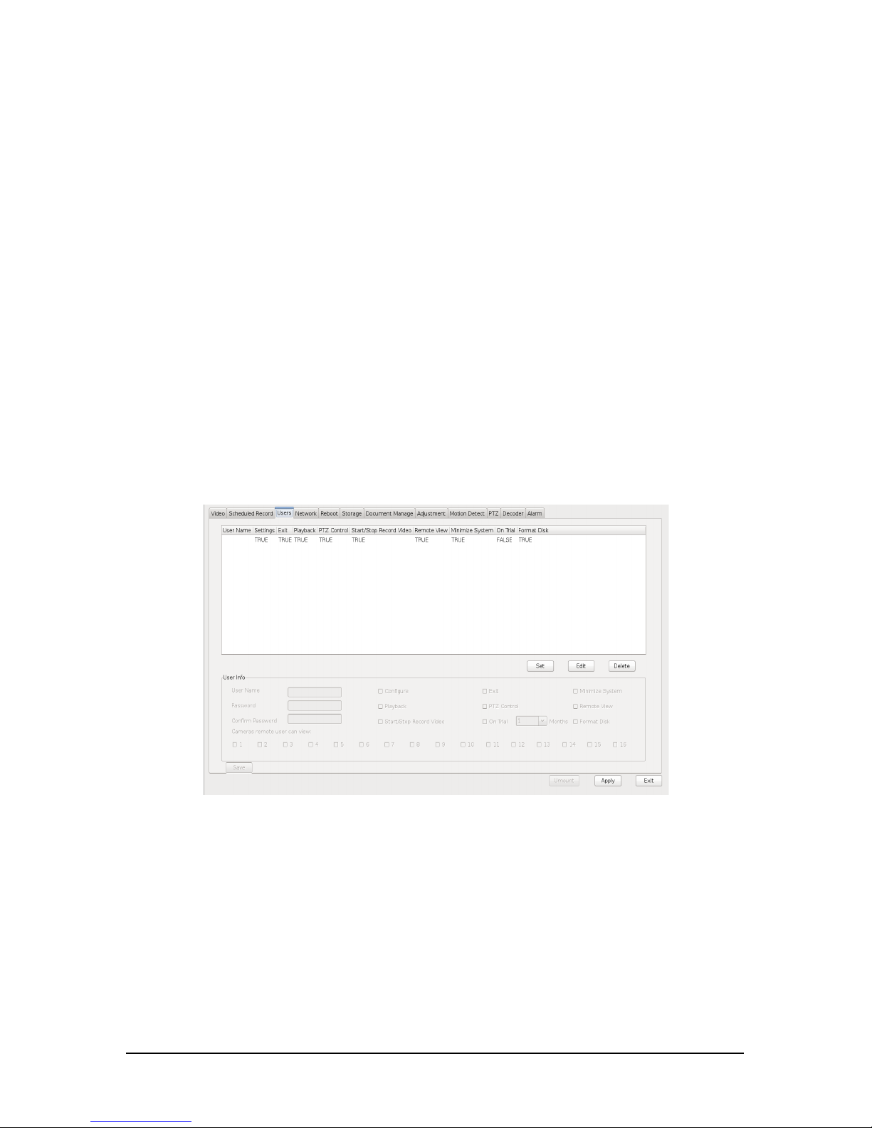
2.2.3 Users
Administrator can setup, manage and change the rights o
f the sub-users.
Click
config
button on the main interface, enter into the
Users
interface as shown.
•Set
Click
Set
to add new user, enter username and password, and check the items you
want the sub-users have.
•Edit
Choose one user,click
Edit
to change setting according to administrator's
requirements.
•Delete
Choose one user,click
Delete
and OK.
•Viewing of cameras remote
Check channels so that user can view the chosen cameras remotely.
Page 17
-11-
User manual of NVR
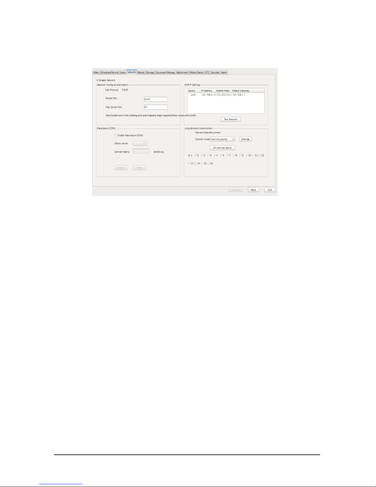
2.2.4 Network
Click
config
button on the main interface, enter into the
Network
interface as
shown.
• Enable network
Check the bo
x to enable remote monitoring.
• Socker Port
The default socket port are 9000、9001、9002,you can change them to others,
such as 9003、9004、9005.
• HTTP Server Port
In general, the default http server port is 80 when remote viewing through IE.
you can also change it to other which is not in conflict with the other networking
softwares in pc system, such as 90,8080. If change 80 to other, input "http" before
the domain name and a colon before HTTP Server Port. For instance, change 80
to 90,you should input: http://*****.dvr99.org:90。
• Enable Manufacture DDNS
Apply for a free domain name with 4-8 characters (letters or numbers). You can
access NVR host After successfully applied.
• NVR IP Setting
Setup the Ip address, subnet mask and gateway of the network card which needs
to connect in the WAN. Eth0 is for public network card and the host's ip address,
subnet mask and gateway should be setup here. Eth1 and Eth2 is RJ45 port of the
cameras.
• Test Network
Click to test whether network is well connected.
• Transfer Mode
There are Space priority and Speed priority for option.
Page 18
-12-
User manual of NVR
Not
es:
1.
When reinstall the NVR system, please delete the domain name first, otherwise the original
domain name cannot be used.
2. 9000、9001、9002 can be changed,the number is better larger than 9000 to avoid conflicts
with the other ports and have to be three sequential numbers, such as 9004,9005, 9006.
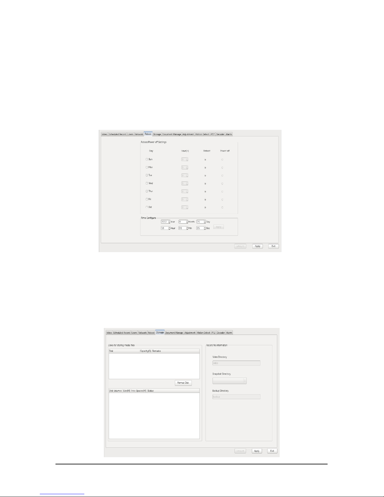
2.2.5 Reboot
Click
c
onfig
button on the main interface, enter into the
Reboot
interface as
shown.
• Reboot/P
ower off settings
Check
Day
to reboot/shutting down NVR.
• Time configure
Set the exact time to reboot/shutting down NVR.
2.2.6 St
orage
Click
config
butt
on on the main interface,enter into the
Storage
interface as
shown.
Page 19
-13-
User manual of NVR
• Disks for storing media files
Show disk's information.
• Format Disk
Click to format the choosen disk.
• Video Directory
• Snapshot Directory
• Backup Directory
NVR system supports recycle recording on multi-hard disks, choose the harddisk
you need to save recording files in. If you choose more than one harddisk,
recording files will be saved one by one, when the first one is full, files will be
automatically saved in the second one, then the third one. When all the harddisks
are almost full, the system will delete the earliest files which is recorded on the first
day in the first harddisk and it will automatically release space.
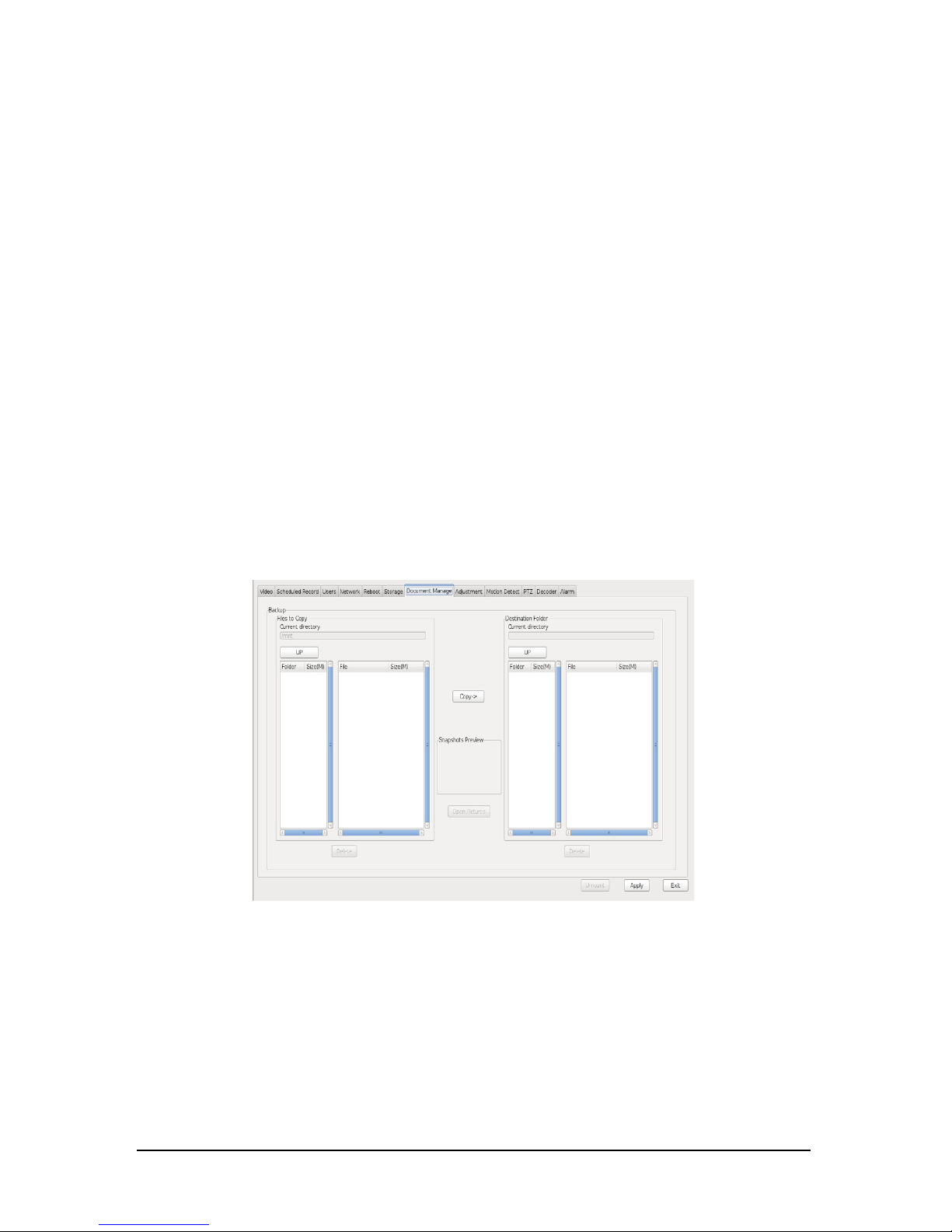
2.2.7 Document management
Click
config
button
on the main interface, enter into the
Document management
interface as shown.
You can b
ackup record files and images to removable storage device.
Steps:
Insert the removable storage device into NVR, Select files to copy on the left list
and select destination folder on the right list,click
copy
to backup. And unmount
removable storage device.
Page 20
-14-
User manual of NVR
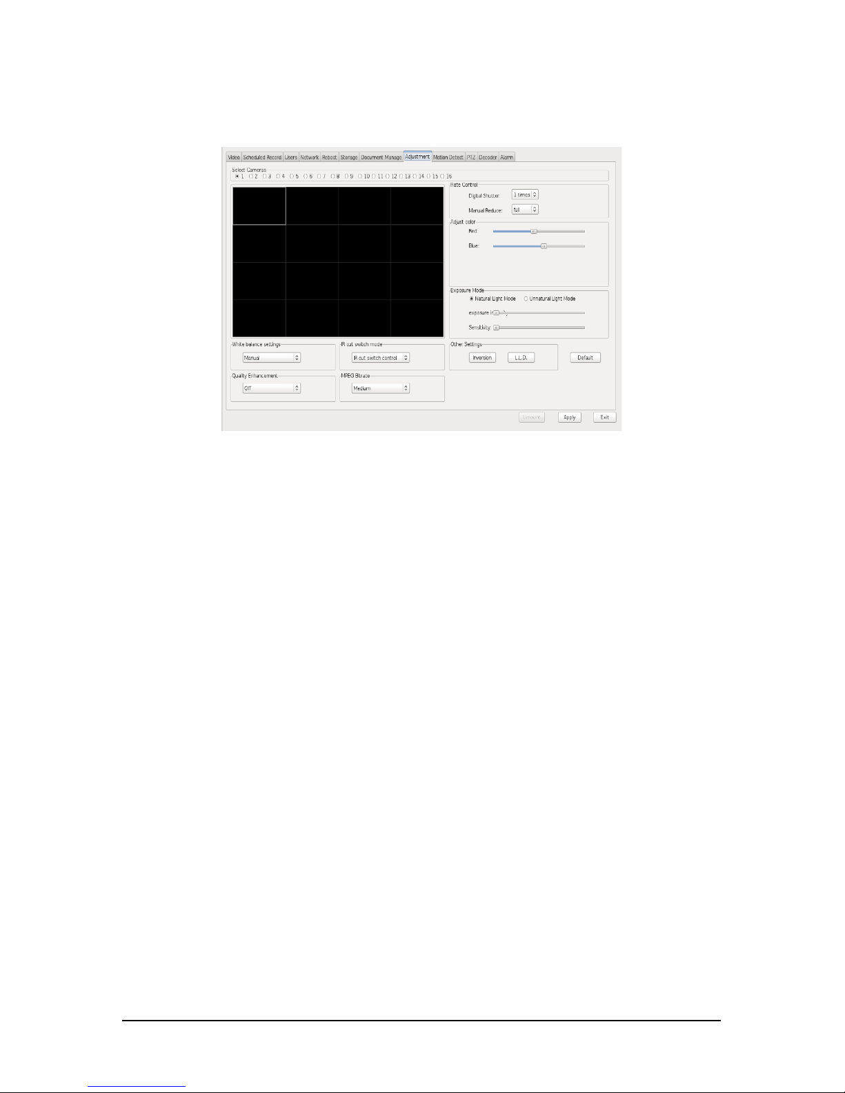
2.2.8 Adjustment
Click
config
button
on the main interface, enter into the
Adjustment
interface as
shown.
•Select Camera
Select the camera you want t
o setup.
•Digital shutter
There are 6 levels for option. By default, it is 1. You can choose 1/4 to avoid
shadow when there is high-speed movement. If the video is too dark when it is 1/4 ,
you can change to 1/2 to increase the brightness.
•Manual Reduce
Decrease frame rate manually, there are 4 levels for option.
•Adjust Color
Drag the Red/Blue bar to adjust the image color.
•Default
Reset options to default.
•Set Balance mode
There are auto,outdoor, fluorescence, manual, indoor, tungsten wire for option.
•Quality Enhancement
Strengthen the image edges to increase the image quality when edge gain is on.
•MPEG Bitrate
There are Low, Medium, High, Default for option.
•Exposure Mode
There are 3 levels for option.
•IR cut switch
1)Hardware switch:Switch according to the outside light with photoresistor.
Page 21
-15-
User manual of NVR
2)Sof
tware switch:Switch according to the brightness of Image.
3)Combine:Switch according to both hardware and software.
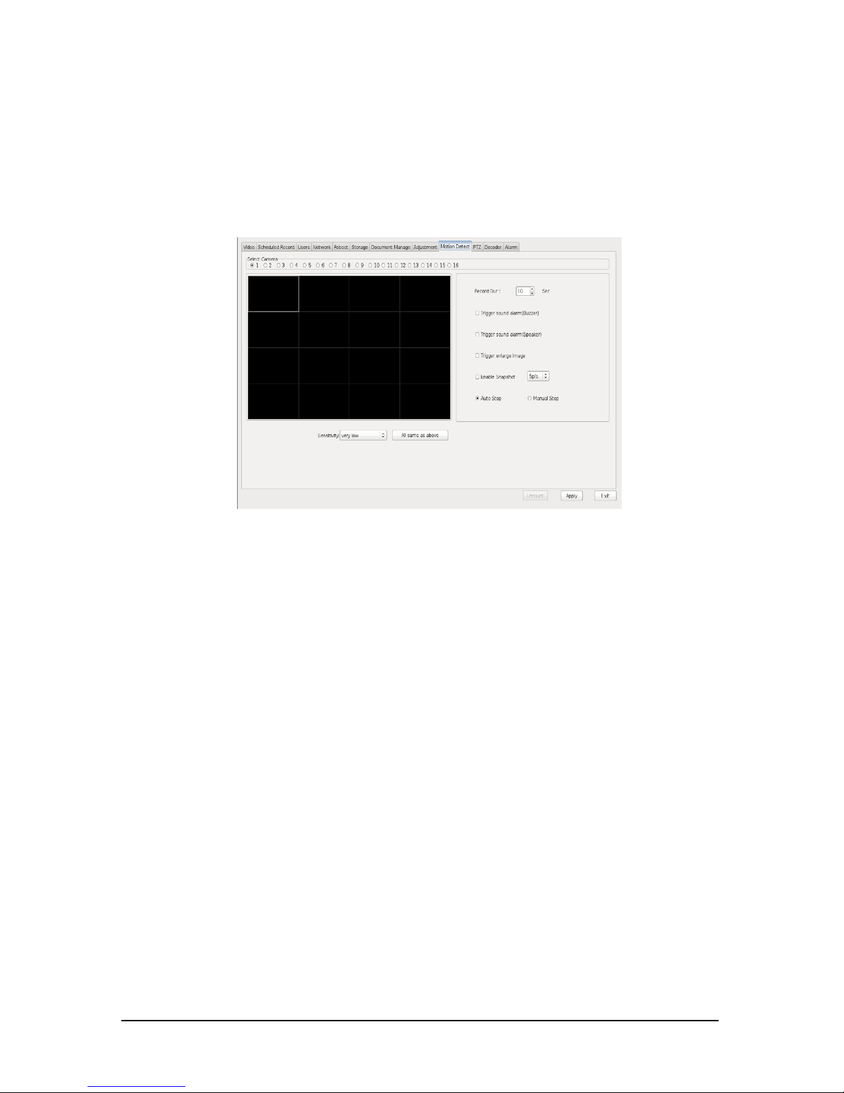
2.2.9 Motion Detection
C
lick
c
onfig
button on the main interface, enter into the
Motion Detection
interface.
• Motion Detection Areas
Select one camera channel and then set the areas you need for motion detection.
You can set multi-zone areas. Left click and drag the red box for motion detection
area. The area can be cleared by draging the right mouse.
• Sensitivity
The higher sensitivity the stronger ability to detect moving objects.
• All Settings the same as above
Click the button if you want to configure same settings to other cameras.
• Record Dur
Duration of NVR continues recording after the moving object disappear in the
detection area.
• Trigger sound alarm(Buzzer/Speaker)
Check the box, it will give an alarm sound when it detects moving object on
selected areas.
• Trigger enlarge image
Check the box, the screen will enlarge to one division when it detects moving
object on selected areas.
• Enable Snapshot
Check the box, the screen will enlarge to one division when it detects moving
object on selected areas.
Page 22
-16-
User manual of NVR
• Auto stop
Auto stop alarm.
• Manual stop
Double click the screen to stop the alarm.
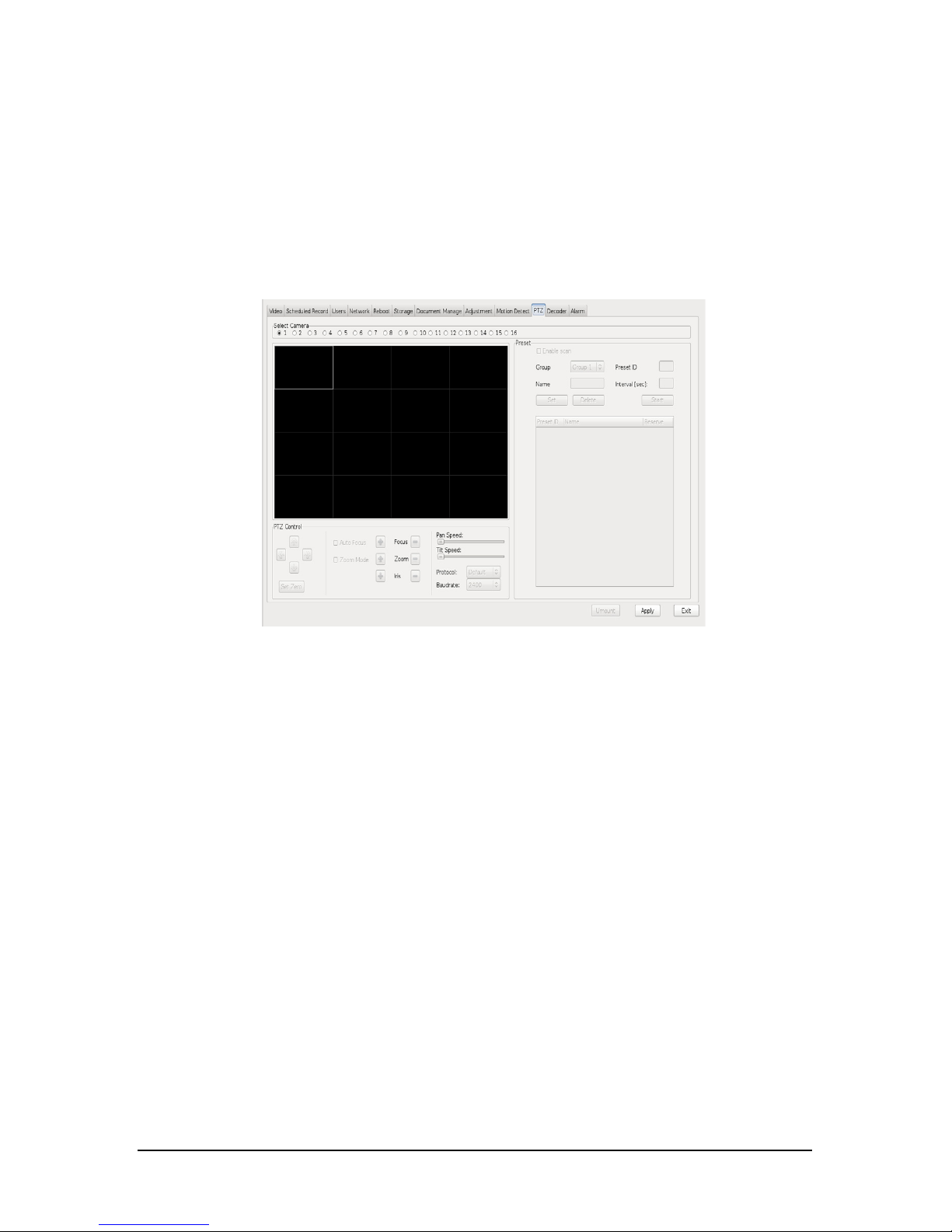
2.2.10 PTZ
Click
config
butt
on on the main int
erface, enter into the
PTZ
interface as shown.
•PTZ Control
Click Up,Down,Left and right arrows to control PTZ rotating.
•Zoom
•Focus
•Iris
•PAN Speed
Adjust PTZ pan speed.
•TILT Speed
Adjust PTZ tilt speed.
•Preset
Set the preset of the dome camera.
1.Setting steps
Choose the camera channel, adjust its location, focus and zoom , enter the preset
ID and preset name, and then click
Set
to save the preset. After successfully added,
the preset ID and preset name will display in the blank area. You can repeat the
steps to add more presets.
2. Presets Using
Right click the video image on the interface of the channel which has presets , a
menu will come out. This menu includes the added preset name and auto- cruise.
Page 23
-17-
User manual of NVR
Click the
preset name, the dome camera will turn to certain position. Click
Cruise
,
the dome camera will auto-rotate among added presets.
• Preset ID
Input ID for new preset.
• Name
Input name for the preset.
• Interval(sec)
The time in seconds to dwell between switching of presets.
• Set
Fill in preset ID, preset name, then click
Set
to make them valid.
• Delete
Choose one preset, click
Delete
to delete it.
• Start
Click to start cruising.
Remark:PTZ control can only work when connecting to digital dome camera
while not analog camera.
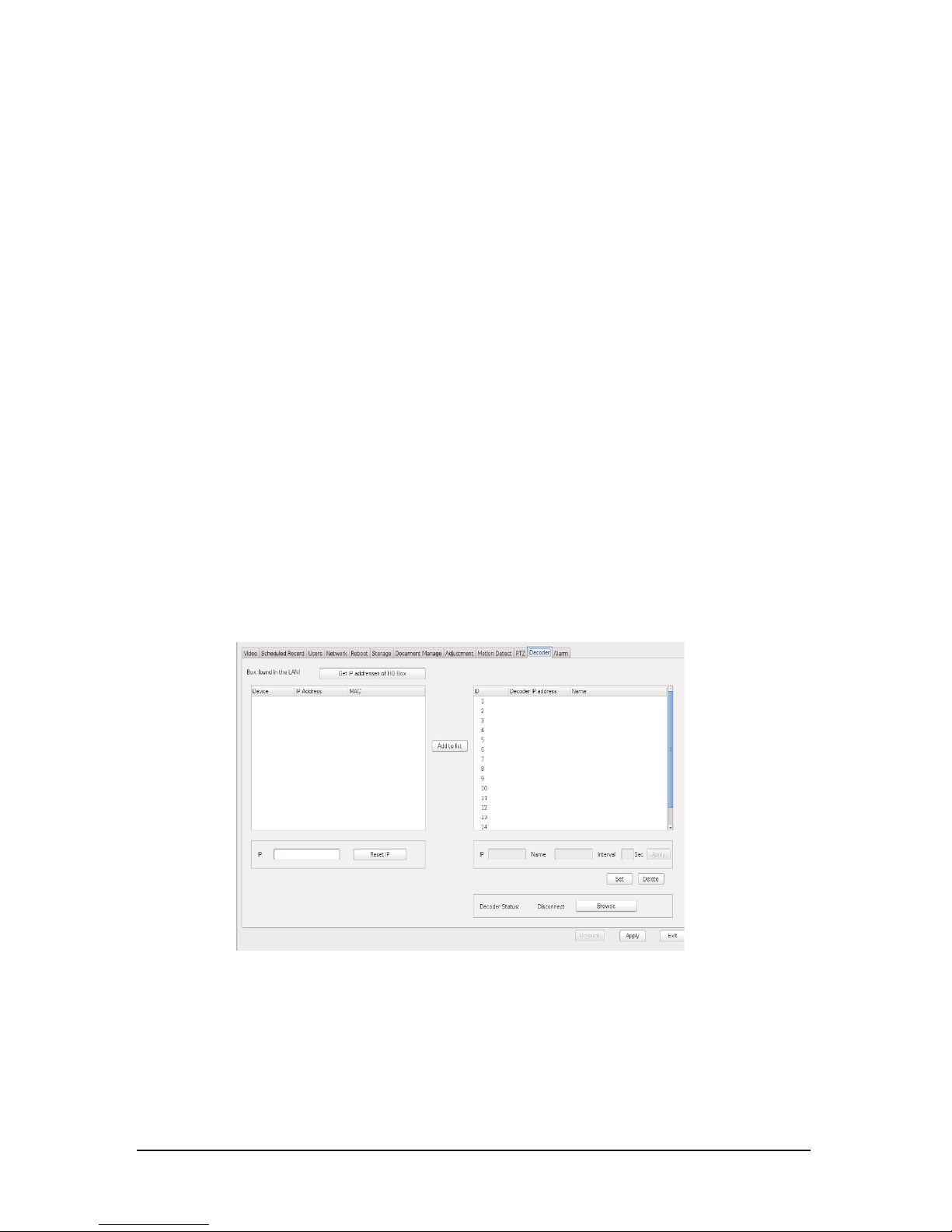
2.2.11 Decoder
Click
config
button on the main int
erface, enter into the
Decoder
interface.
•Get IP addresses of HD Decoder
Search decoders in LAN.
•IP Address
Show the IP of the added decoder.
•Name
Input the name for added decoder.
Page 24
-18-
User manual of NVR
•Add to list
Select one decoder on the left list, click
Add to list
. All added decoders will be
shown in the right list.
•
Reset IP
Select one decoder on the left list, input new IP, click
Reset
to make it valid.
•Delete
Delete the added decoder.
•Set
Input IP and
Name
, and then click
set
to add decoder manually.
•
Interval(sec)
The time in seconds to dwell between switching cameras.
Remark:The decoder will aut
o restart after changing IP address. This takes about 1min.
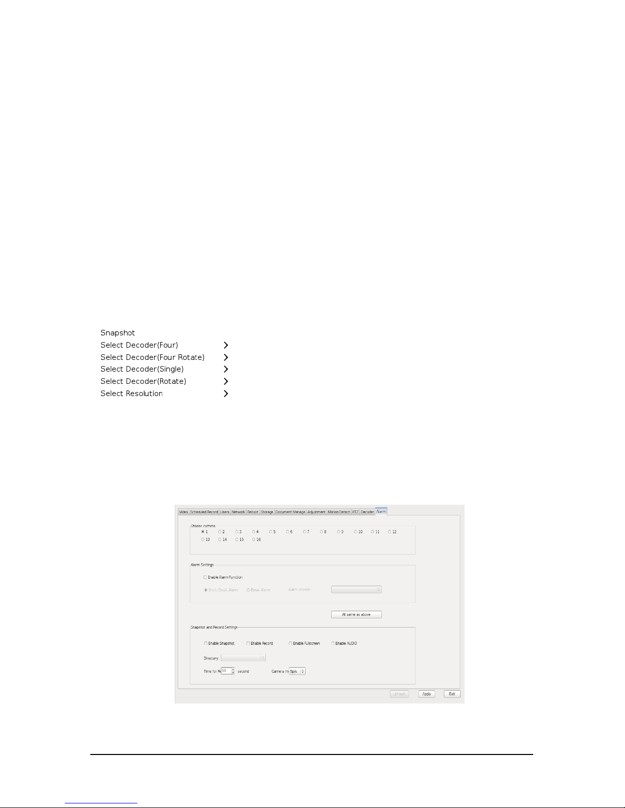
NVR videos switch to TV
After successfully adding the decoder, go back to the main interface, right click on
the image which you want to switch to TV , the menu will come out as shown.
Click Decoder name and then select mode to switch to TV .
2.2.12 Alarm
Click
config
button on the main int
erface, enter into the
Alarm
interface.
• Alarm Settings
Check
Enable Alarm Function
, you can choose shot-circuit alarm or Break alarm.
Page 25

-19-
User manual of NVR
•
Select camera
Select the camera you want t
o setup.
• Short-circuit
When there is short-circut, alarm will be working.
•
Break Alarm
When there is break alarm,alarm will be working.
• Enable Snapshot
Check the box, NVR will take a snapshot once the alarm triggering.
• Enable record
Check the box, NVR will start recording once the alarm triggering.
• Enable Fullscreen
Check the box, NVR will enlarge image to fullscreen once the alarm triggering.
•
Enable Audio
Check the box, NVR will alarm in sound once the alarm triggering.
• Directory
Path to store images and record files of alarm.
• Time for record
Duration of NVR continues recording after the alarm triggering.
Page 26
-20-
User manual of NVR
2.3 Remot
e view
2.3.1 Network S
tructure
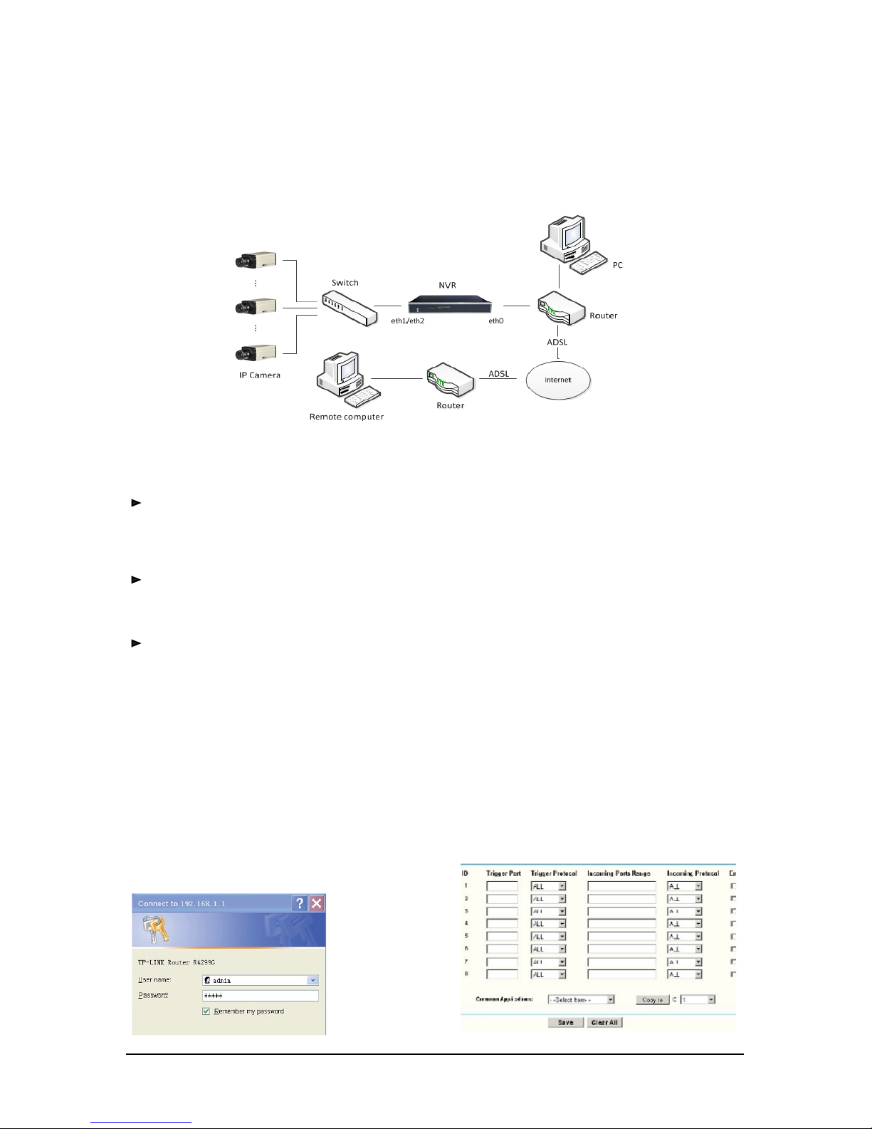
Syst
em Network is as shown.
2.3.2 Network Setting
Remot
e access to the host through a fixed IP and Dynamic Domain Name.
•
LAN user
s can access through fixed IP or dynamic domain name.
•
ADSL users can access only thr
ough dynamic domain name .
Remot
e View Via IP
Users could access to the host through fixed IP, just add host IP address in remote
monitoring software.(please refer to 2.3.3 and 2.3.4 for setting )
Remot
e View Via Dynamic Domain Name
1) Remote view through internet need to set up host-side router.
The methods to connect internet in most companies and families are :
PC ---Router---Modem ADSL ---Internet
The settings vary depending on different models of routers. We take TP-LINK router
for example:
Click "Internet Explorer",open the IE browser, input http://192.168.1.1 then
confirm
,
coming to next interface as bellow. Enter username and password, click
port
forwarding
in the list on the left side. According to the picture below, forward the
ports 80 9000 9001 9002 to corresponding private IP (assume host IP is 192.168.1.3)
then save it .
Page 27
-21-
User manual of NVR
2)
Register a dynamic domain name through NVR software , please refer to 2.2.4.
After successful registration, you could Monitoring host through dynamic domain
name.
2.3.3 Using IE Remot
e Monitoring System
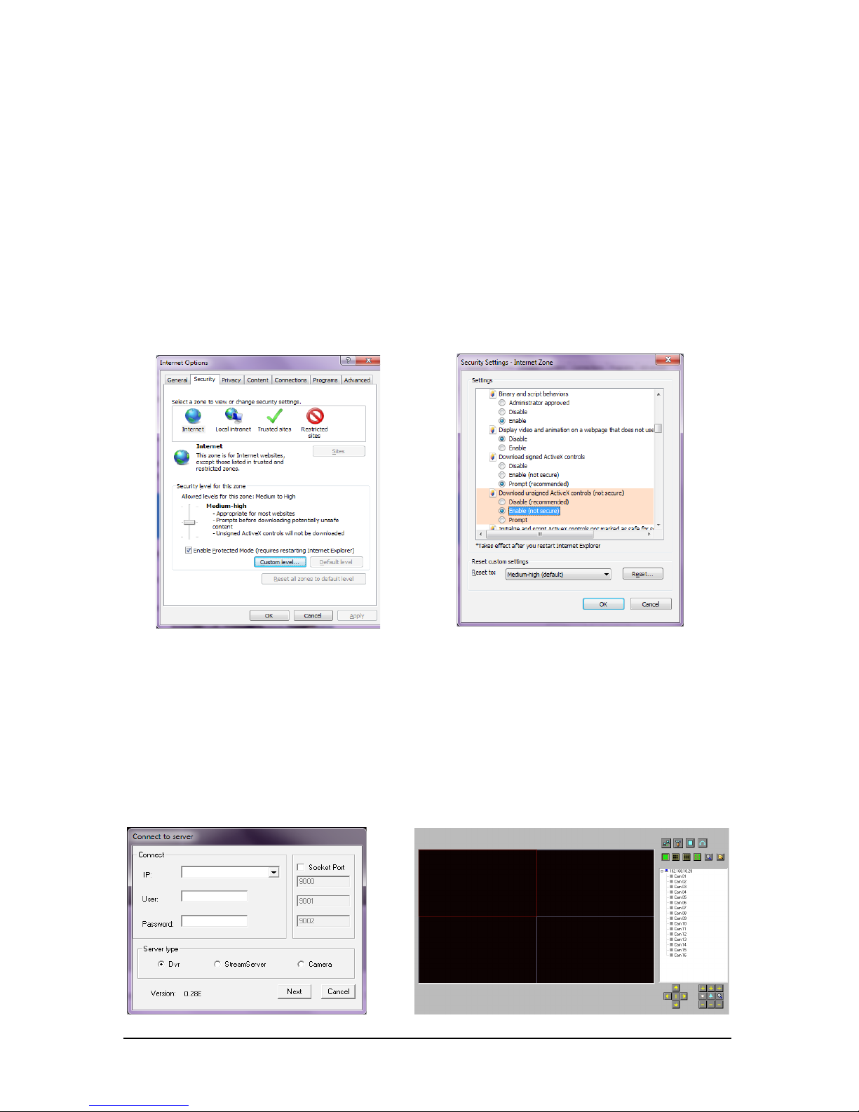
Please set the security o
f IE corr
ectly before remote view,steps are as follows:
1)Right click the icon
internet explorer
on the desktop,click
property
in the
menu;
2)Click
custom level
, come into the dialog box of
security setup
,
enable
download unsigned Active X
.
3) click
confirm
, IE security setup finished, you can view through IE remotely.
•Connecting to Host
1. First you need to install
WEBVIEW
, and then Input host IP address or dynamic
domain name and HTTP port in the IE browser address bar, click enter key to go
to figure A, For example: assume the NVR host IP is 192.168.1.200, http port is 99,
then, enter http://192.168.1.200:99/ in the IE address bar.
2. Enter IP, User,Password,Server type,and Socket Port in figure A, a camera ID list
will come out on figure B when successfully connecting.
Figure A Figure B
Page 28

-22-
User manual of NVR
3) Click on
figure B to get figure A again,Enter IP, User,Password of other NVR
servers. Then you could monitor several NVRS under the same IE.
• Playb
ack local files r
emotely
Click button,coming
to
open DVR file
dialog box, find a "*.DVR" file and play
it.
Remarks:
Remarks:
1. please close the firewall of the host as well as remote computer before remote connecting
through IE.
2. You could view maximum 16ch at the same time in one computer when remote view by IE.
3. Totally, you could view maximum 64ch remotely for the same NVR host. When the total
amount of CHs which are remotely viewed via IE by many computers are more than 64CHs at
the same time, the IE side will get the message "please close the other cameras" or "please
connect later".
Page 29
-23-
User manual of NVR
2.3.4 Central Monitor
ing System
2.3.4.1 User Instruction
1. Please put the file dvr_caption_en.ini under the direct
ory of C:\windows.
2. Please open the folder RCMS system, and double click RCMS.exe to run the
system.
Remarks: Please do not open the dvr_caption_en.ini file at random, it will easily
lead to characters changed to be irrecognizable because different coder or
other reasons.
2.3.4.2 Local Settings
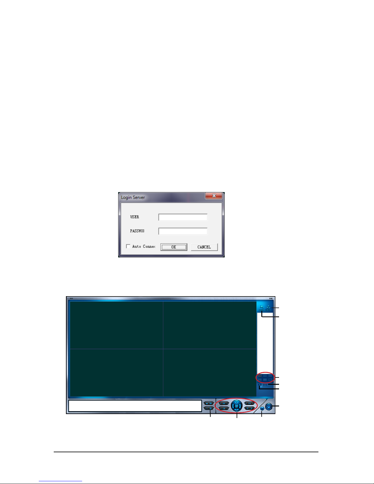
1.Double click the RCMS.exe, you will see the interface as the following picture. The
default USER and PWD(p
assword) are all blank. Please click “OK”to enter.
2.There are two icons on the right part of the main interface ---
Local setting
and
remote setting
.
3.
Please enter the
Local setting
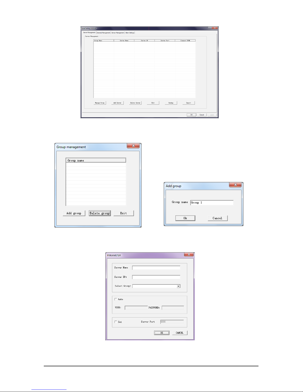
, y
ou will see the picture below.
Lock/Unlock
PTZ Control
Minimize
Shut Down
Playback
Bright
en
Screen Mode
Local Setting
Remote Setting
Page 30
-24-
User manual of NVR
4.Creat
e a Group. Click
Manage Group
and click
ADD
and then input group name,
such as “Group 1” and then click OK.
5.Add the server. Please click
Add Server
, input the server name and input host's
(NVR) IP address or domain name (such as 192.168.10.34) at first. Then select the
group (such as“Group 1”) for the server. Then please click OK.
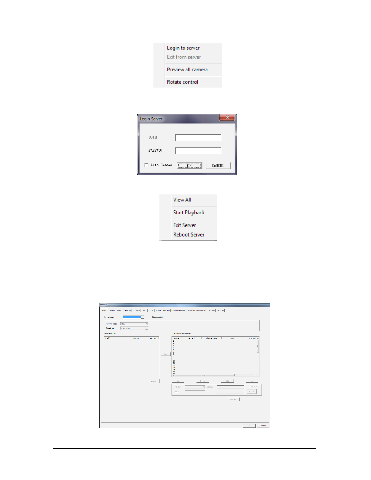
6.Please go back to the main interface. You will see that there is a Group named
“Group 1” listed at the right list of the interface which you just created. Right click
Page 31
-25-
User manual of NVR
the specific serv
er name, then click
login server
to get connected.
7.You will see the picture as follows. Please click
OK
and you will get connection to
the server.
8.After the connection is built, Please right click the specific server name again and
click
View All
,then you will get the video of the remote server.
2.3.4.3 Remot
e Settings
• Back up remotely
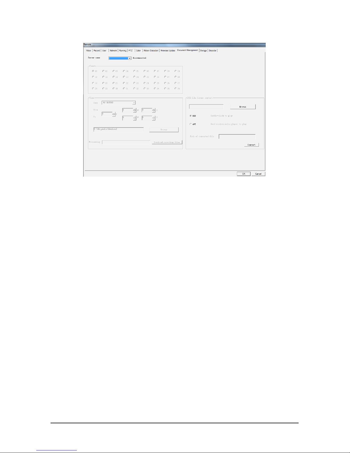
1.When NVR
is connected, click the
remote setting
in the main interface. You will
see the interface as below.
Page 32
-26-
User manual of NVR
2.Please go to
Document Manage
it
em, you will see interface as follows:
Please select the server name you want to back up. Then do as follows.
a.Select the camera you want to back up.
b.Select the date and time for back up.
c.Select the directory for back up.
d.Click
Download Video
to start the download.
After finishing download, the video file in dvr. format is saved under the directory
for back up.
If you want to convert the video file from DVR format to EXE or AVI format, please
do as follows:
a.Click
Select DVR File
to select the video file in DVR format.
b.Please select
EXE
or
AVI
format.
c.Click
File conversion
to convert.
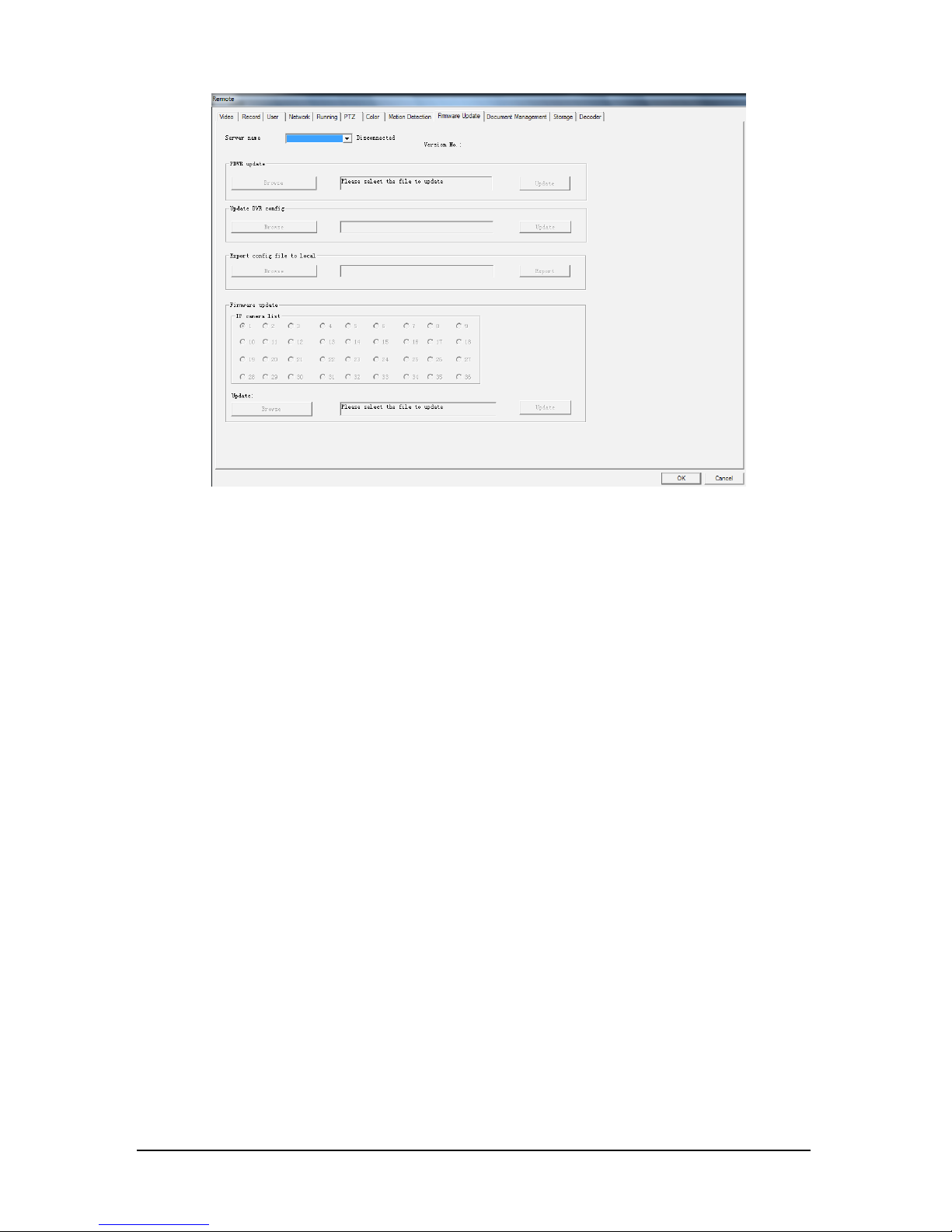
• Update NVR Fir
mware System
1.When
NVR is connected, click the
remote setting
icon in the main interface.
Please go to the item
Firmware Update
. Select the NVR needed to be updated
(server name) and click
SELECT UPDATE FILE
to choose the file (called "Linux_dvr_
update" ) and click
Update
button.
Page 33
-27-
User manual of NVR
2.When the updating process finishes, the NVR would restart. It means NVR is
updated successfully.
Page 34
-28-
User manual of NVR
CHAPTER 3 S
yst
em Installation
1.Downlo
ad mapping file o
f the NVR system;
2.Extract files and install
ifw_en_trial
(using the default options), and you will get
shortcut of
Image for windows
on the desktop;
3.Insert Pen drive to the computer, and format it;
4.Double click
Image for Windows
on the desktop;
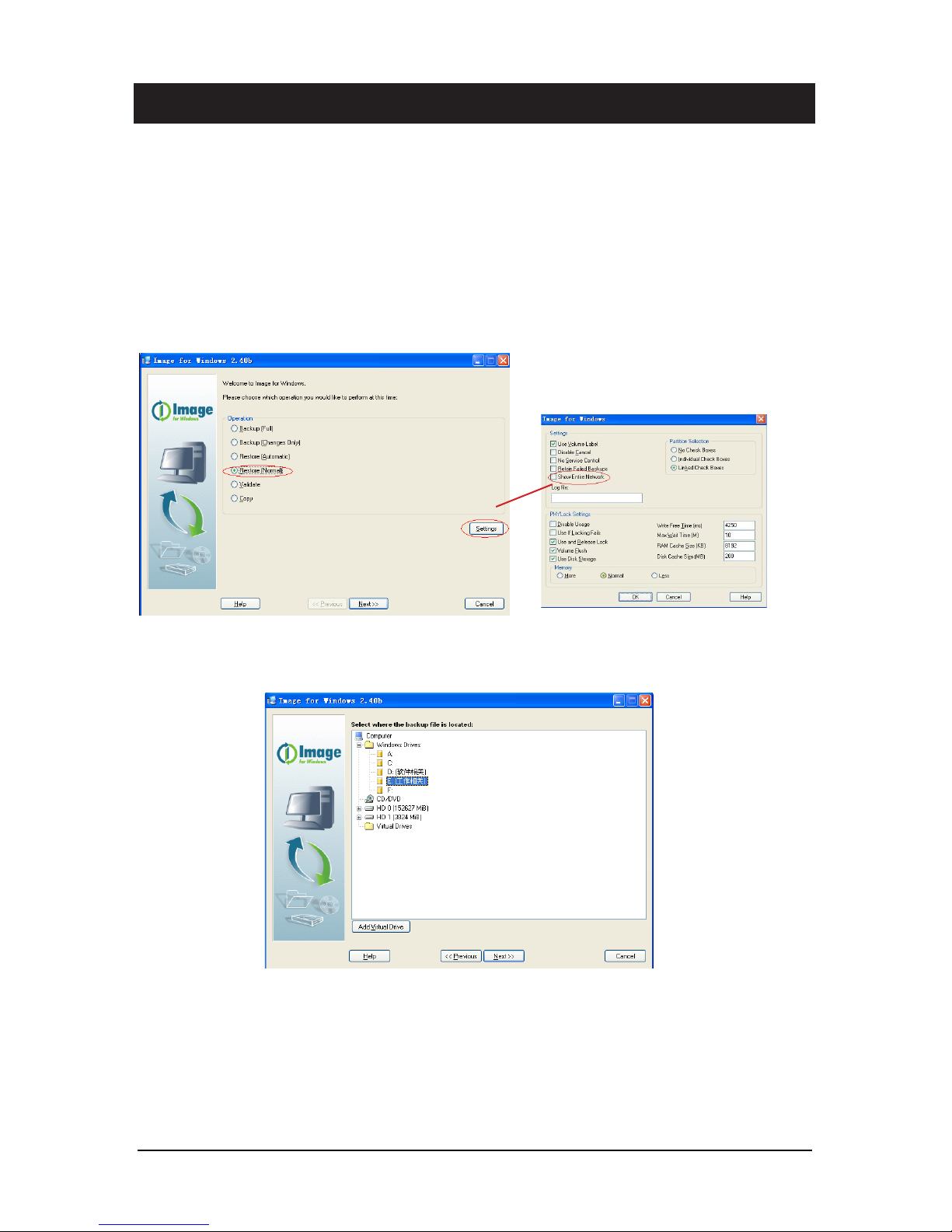
5.Uncheck
show Entire Network
in
Settings
, and go back to select
Restore(Normal)
,click
Next
;
6.Select the disk you have stored the mapping file, and then click
Next
;
Page 35
-29-
User manual of NVR
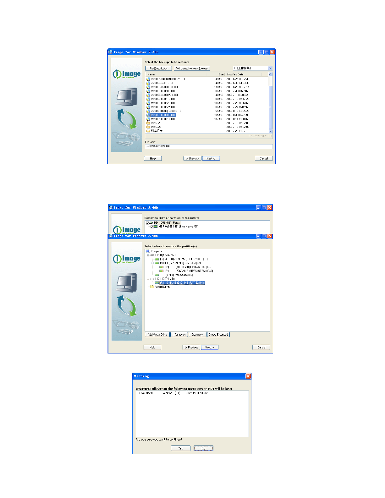
7. Select the mapping file you hav
e download and then click
Next
;
8. Select the Destination directory(the Pen drive ),and then click
Next
;
9.Click
Yes
;
Page 36
-30-
User manual of NVR
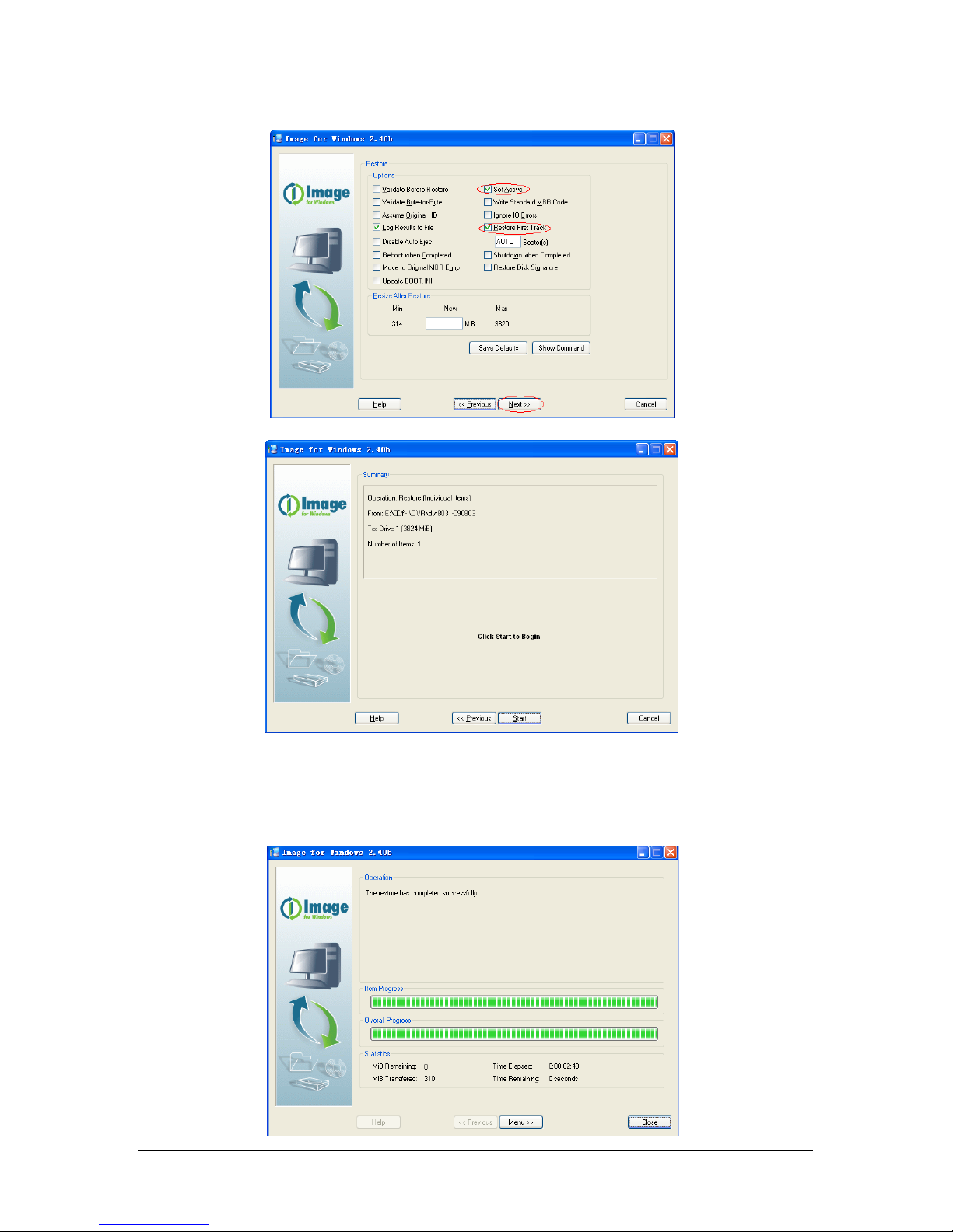
10. Check
Set Active
and
R
estore First Track
, click
Next
,and then click
Start
;
11.Click
Close
after finishing restoring,unmount Pen drive,then insert the Pen
drive into NVR,and then start up NVR;
Page 37

-31-
User manual of NVR
12.
The
system will autoamtic install when starting up,Please input Y and press
enter
when it comes out:
“Are you sure to be continue ?(y or n):)”
13.NVR will shutdown when successfully installing, remove Pen drive and then start
up NVR.
Notes:
1.Please for
mat the Pen drive before restoring NVR system to it;
2.Please do not remove Pen drive during the installation;
Page 38

Page 39

Page 40

USER MANUAL
 Loading...