

Page 1
INSTRUCTIONS
Manual Reset Relay
Part # 835220
2370 Firehall Road • PO Box 730
Canandaigua, N Y 14424
1.800.828.9638 • 1.585.394.8692
2370 Firehall Road • P.O. Box 730 • Canandaigua, NY 14424
1.800.828.9638 • 1.585.394.8692
Reset Relay 10A, 220VAC
External Control Switch Closure Required
835220WD
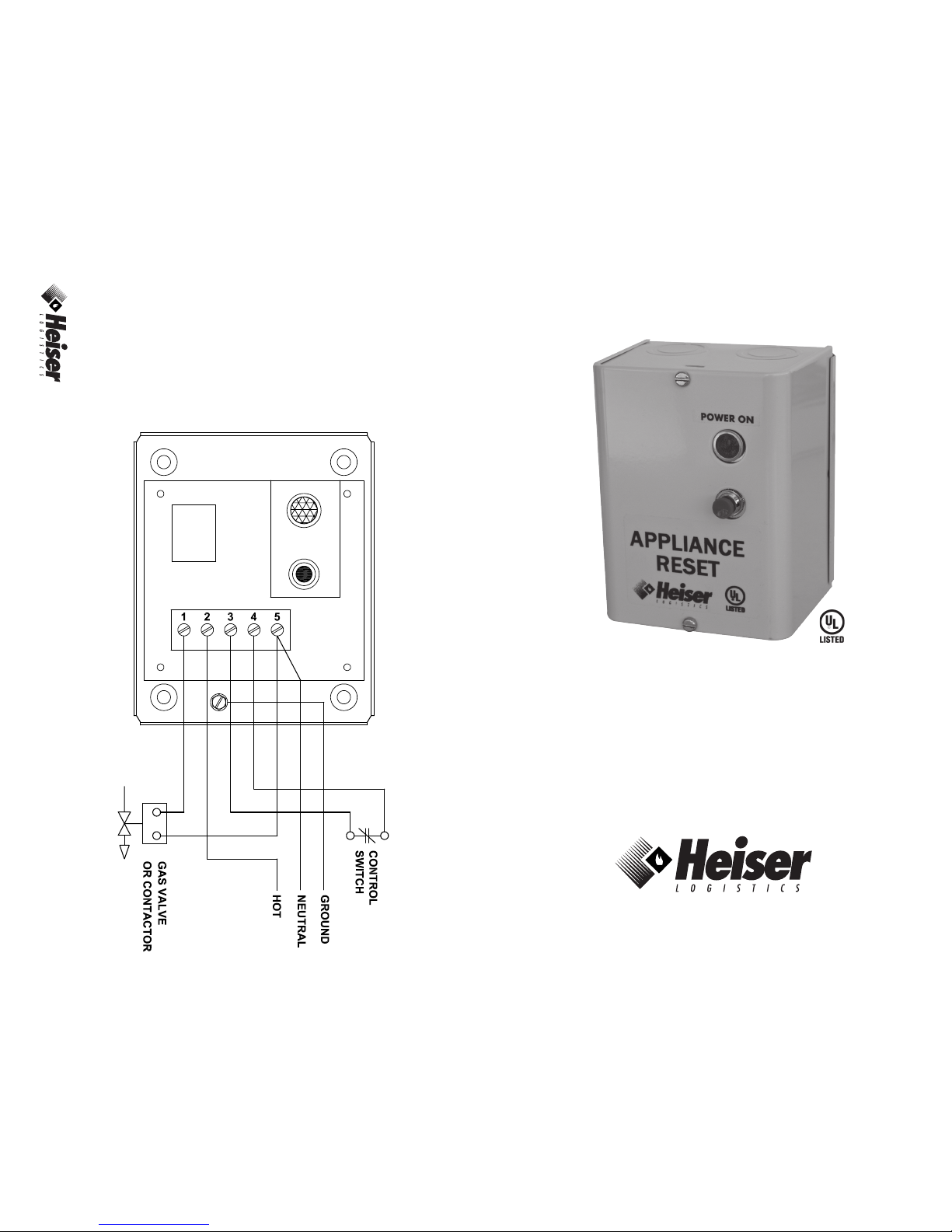
NOTE 1– Control
switch must be closed
before the reset switch
can be pressed.
NOTE 2– To test, apply
220VAC to terminals
2 and 5. Then jumper
3 and 4. Push the
reset and relay should
operate. Remove
jumper and relay will
drop out.
All external wiring
must conform to local
electrical code.
BE-12 53
Page 2
INSTRUCTIONS
#835220 Manual Reset Relay
The 835220 is a manual reset intended to prevent the unintended restoration of
power to a gas or electric powered appliance. In the event of a power failure or
the release of a connected control switch, the 835220 interrupts power to a gas
valve or electrical contactor, shutting down the appliance. The fuel or power
supply to the appliance is restored only after the control switch has been set,
and the 835220 has been manually reset by pushing the reset switch on the
835220. When power is being supplied to the gas valve or electrical contactor,
the red indicator light is on. The red indicator light is off when power is not
supplied to the gas valve or electrical contactor.
INSTALLATION
1. Mount the 835220 in a suitable location.
2. Install 220VAC, 60HZ power line.
a. Hot (black) wire to terminal 2
b. Neutral (white) wire to terminal 5
3. Test unit by jumpering terminals 3 and 4 and pushing reset switch.
Note: Relay should operate and lamp should come on.
4. If relay operates, remove jumper from terminals 3 and 4.
5. Install wires from control switch to terminals 3 and 4.
6. Install one side of load cable to terminal 1, the other to terminal 5
7. Set control switch to closed position.
8. Operate the reset switch. Lamp should come on indicating that power is
being supplied to the load.
9. Remove wire on terminal 4 from control switch and unit should deactivate,
turning off the red lamp and the load. If not, recheck your wiring.
10. If system works as stated, reconnect wire to terminal 4.
11. Operate reset switch to activate load (gas valve or contactor).
12. Installation is complete.
WIRING: All Wiring Must Comply With Applicable Codes, Regulations, and
Ordinances.
© 2012 The written material and photographs in this brochure are copyrighted and
may not be reproduced without written permission.
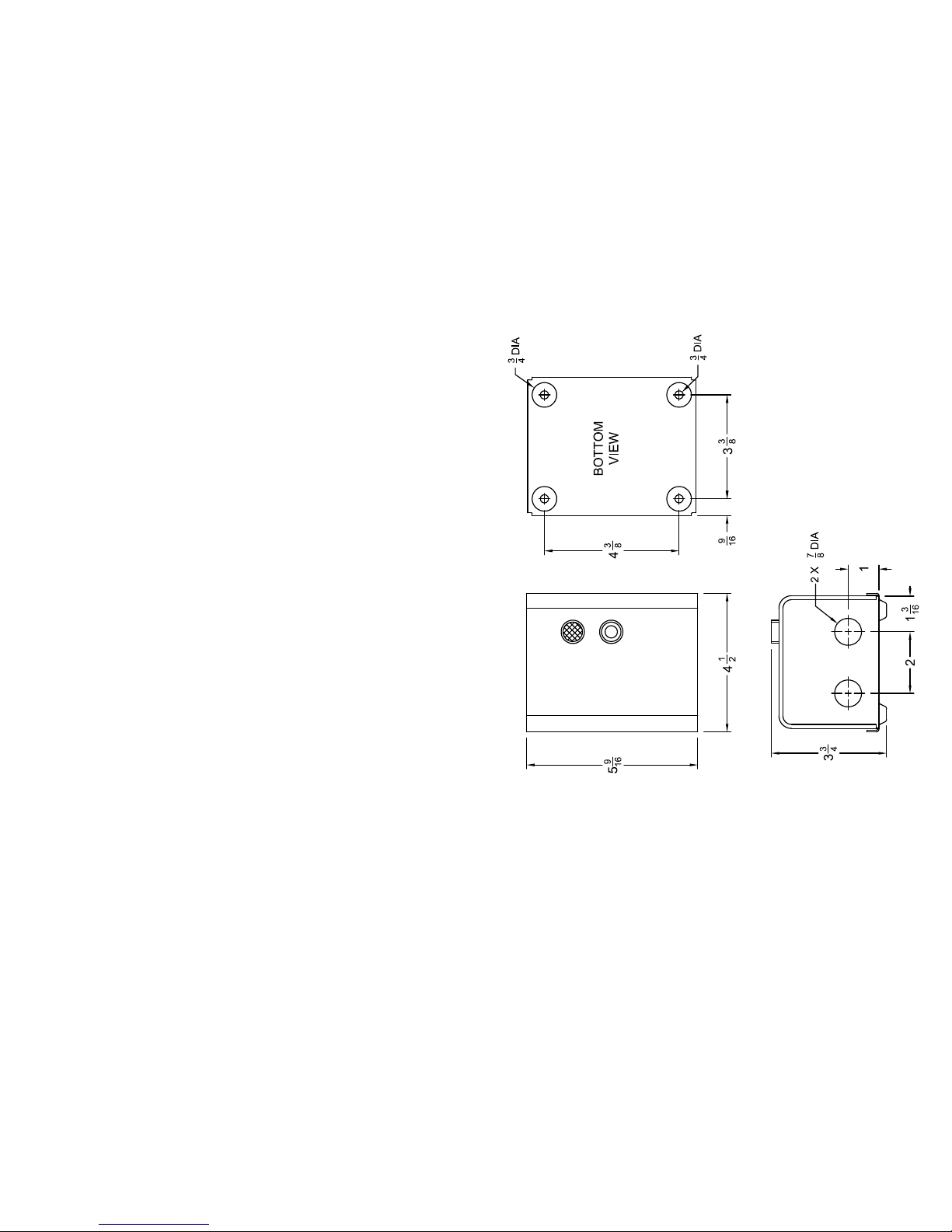
MOUNTING DIMENSIONS
 Loading...