


Engine & Turbine Management
Am Haselbach 1
D-79677 Schönau
Germany
Phone +49 7673 8208-0
Fax +49 7673 8208-188
E-mail info@heinzmann.com
www.heinzmann.com
V.A.T. No.: DE145551926
Heinzmann GmbH & Co. KG
HEINZMANN®
Digital Speed Governors
Digital Basic System
PANDAROS - III
DG 16.6 - 01 up to - 05
DG 30.6 - 01 up to – 05
DG 40.6 - 01 up to - 05
This publication may not be reproduced by any means whatsoever or passed on to any third parties.
6685 Manual DG 01 010-e / 01-14
Copyright 2014 by Heinzmann GmbH & Co. KG. All rights reserved.


The appropriate manuals must be thoroughly studied before
installation, initial start-up and maintenance.
All instructions pertaining to the system and safety must be followed in
full. Non-observance of the instructions may lead to injury to persons
and/or material damage.
HEINZMANN shall not be held liable for any damage caused through
non-observance of instructions.
Independent tests and inspections are of particular importance for all
applications in which a malfunction could result in injury to persons or
material damage.
All examples and data, as well as all other information in this manual
are there solely for the purpose of instruction and they may not be used
for special application without the operator running independent tests
and inspections beforehand.
HEINZMANN does not guarantee, neither expressly nor tacitly, that
the examples, data or other information in this manual is free from
error, complies with industrial standards or fulfils the requirements of
any special application.
To avoid any injury to persons and damage to systems, the
following monitoring and protective systems must be provided:
Overspeed protection independent of the rpm controller
HEINZMANN shall not be held liable for any damage caused through
missing or insufficiently rated overspeed protection.
thermal overload protection
The following must also be provided for alternator systems:
Overcurrent protection
Protection against faulty synchronisation for excessively-large frequency, voltage or
phase difference
Directional contactor
The reasons for overspeeding may be:
Failure of positioning device, control unit or its auxiliary devices
Linkage sluggishness and jamming
The following must be observed before an installation:
Always disconnect the electrical mains supply before any interventions to the system.
Only use cable screening and mains supply connections that correspond with the
European Union EMC Directive
Check the function of all installed protection and monitoring systems

Please observe the following for electronically controlled injection
(MVC):
For common rail systems each injector line must be equipped with a separate
mechanical flow-rate limiter
For unit pump (PLD) and pump-injector unit (PDE) systems, the fuel enable is
first made possible by the solenoid valve’s control plunger motion. This means that
in the event of the control plunger sticking, the fuel supply to the injection valve is
stopped.
As soon as the positioning device receives power, it can actuate the
controller output shaft automatically at any given time. The range of the
controller shaft or control linkage must therefore be secured against
unauthorised access.
HEINZMANN expressly rejects any implied guarantee pertaining to
any marketability or suitability for a special purpose, including in the
event that HEINZMANN was notified of such a special purpose or the
manual contains a reference to such a special purpose.
HEINZMANN shall not be held liable for any indirect and direct
damage nor for any incidental and consequential damage that results
from application of any of the examples, data or miscellaneous
information as given in this manual.
HEINZMANN shall not provide any guarantee for the design and planning
of the overall technical system. This is a matter of the operator its planners
and its specialist engineers. They are also responsible for checking whether
the performances of our devices match the intended purpose. The operator is
also responsible for a correct initial start-up of the overall system.


Contents
Contents
Page
1 Safety instructions and related symbols .............................................................................. 1
1.1 Basic safety measures for normal operation ............................................................... 2
1.2 Basic safety measures for servicing and maintenance ................................................ 2
1.3 Before putting an installation into service after naintenance and repair works ......... 2
2 General ................................................................................................................................... 3
3 Functions ................................................................................................................................ 5
3.1 General functions ............................................................................................................. 5
3.2 Variation specific additional functions ............................................................................ 6
3.2.1 Variation DC 6-01 (standard generator) .................................................................... 6
3.2.2 Variation DC 6-02 (standard general) ....................................................................... 6
3.2.3 Variation DC 6-03 (extended generator 1) ................................................................ 7
3.2.4 Variation DC 6-04 (extended generator 2) ................................................................ 7
3.2.5 Variation DC 6-05 (extended general, especially vehicle) ........................................ 7
4 Further information .............................................................................................................. 9
5 Block diagram ...................................................................................................................... 11
6 Sensors .................................................................................................................................. 13
6.1 Overview ....................................................................................................................... 13
6.2 Magnetic pick-up IA ... .................................................................................................. 14
6.2.1 Technical data.......................................................................................................... 14
6.2.2 Installation ............................................................................................................... 14
6.2.3 Tooth profile ............................................................................................................ 15
6.2.4 Clearance of magnetic pick-up ................................................................................ 15
6.2.5 Dimensions .............................................................................................................. 16
6.3 Cooling medium temperature sensor TS 01 - 28 - PT 1000 (EDV- No.: 600 00 053 00) ....... 17
6.4 Pressure sensors ............................................................................................................. 18
6.4.1 Oil pressure sensor .................................................................................................. 18
6.4.2 Boost pressure sensors............................................................................................. 19
6.4.2.1 Boost pressure sensor with plug ....................................................................... 19
6.4.2.2 Boost Pressure Sensor with Housing and Terminal Strip ................................ 20
Digital Governor Basic System PANDAROS III

Contents
7 Setpoint adjusters ................................................................................................................ 21
7.1 Setpoint potentiometer SW 01 - 1 - b (1 turn) (EDV- No.: 600 00 041 01) .................. 21
7.2 Setpoint potentiometer SW 02 - 10 - b (10- turn) (EDV- No.: 600 00 042 01) ............ 21
7.3 Setpoint value adjustment by current signal .................................................................. 22
7.4 Digital presetting of setpoint values .............................................................................. 22
7.5 Setpoint value adjustment by pedal ............................................................................... 22
7.6 Pneumatic setpoint adjuster ........................................................................................... 22
8 Control unit DC 6 – 01 ... 05 ............................................................................................... 23
8.1 Specification .................................................................................................................. 23
8.1.1 General .................................................................................................................... 23
8.1.2 Inputs and outputs ................................................................................................... 24
8.2 Dimensions .................................................................................................................... 25
8.3 Mounting ....................................................................................................................... 26
9 Actuators .............................................................................................................................. 27
9.1 Design and Mode of Operation...................................................................................... 27
9.2 Installation ..................................................................................................................... 28
9.3 Specification .................................................................................................................. 29
9.4 Dimensions .................................................................................................................... 30
10 Regulating linkage ............................................................................................................. 31
10.1 Length of lever arm ..................................................................................................... 31
10.2 Order specification for lever arm ................................................................................. 31
10.3 Connecting linkage ...................................................................................................... 31
10.3.1 Linkage adjustment for diesel engines .................................................................. 32
10.3.2 Linkage adjustment for carburettor engines .......................................................... 33
11 Electrical connection ......................................................................................................... 35
11.1 Connection for variation DG 6-01 (standard generator) .............................................. 35
11.2 Connection for variation DG 6-02 (standard general) ................................................. 36
11.3 Connection for variation DG 6-03 (extended generator 1) .......................................... 37
11.4 Connection for variation DG 6-04 (extended generator 2) .......................................... 38
11.5 Connection for variation DG 6-05 (extended general) ................................................ 39
11.6 Harness ........................................................................................................................ 40
12 Parametrization options .................................................................................................... 43
12.1 Parametrization at the factory ...................................................................................... 43
12.2 Parametrization with the Hand Held Programmer HP 03 ........................................... 43
12.3 Parametrization with the PC ........................................................................................ 43
Digital Governor Basic System PANDAROS III

Contents
12.4 Parametrization with user mask ................................................................................... 44
12.5 Transferring data sets ................................................................................................... 44
12.6 Assembly line end programming ................................................................................. 44
13 Starting the engine - brief instruction ............................................................................. 45
14 Download of manuals ........................................................................................................ 47
Digital Governor Basic System PANDAROS III

1 Safety instructions and related symbols
DANGER indicates a hazardous situation the consequence of which could
be fatal or severe injuries if it is not prevented.
WARNING indicates a hazardous situation which could lead to fatal injury
or severe injuries if it is not prevented.
CAUTION indicates a hazardous situation which could lead to minor
injuries if it is not prevented.
NOTICE indicates possible material damage.
Safety instructions are not only denoted by a signal word but also by hazard
warning triangles. Hazard warning triangles can contain different symbols
to illustrate the danger. However, the symbol used is no substitute for the
actual text of the safety instructions. The text must therefore always be read
in full!
This symbol does not refer to any safety instructions but offers important
notes for better understanding the functions that are being discussed. They
should by all means be observed and practiced.
1 Safety instructions and related symbols
This publication offers wherever necessary practical safety instructions to indicate inevitable
residual risks when operating the engine. These residual risks imply dangers to
- Personnel
- Product and machine
- The environment
The primary aim of the safety instructions is to prevent personal injury!
The signal words used in this publication are specifically designed to direct your attention to possible
damage extent!
Digital Governor Basic System PANDAROS III 1

1 Safety instructions and related symbols
In this publication the Table of Contents is preceded by diverse instructions that among
other things serve to ensure safety of operation. It is absolutely imperative that these
hints be read and understood before commissioning or servicing the installation.
1.1 Basic safety measures for normal operation
The installation may be operated only by authorized persons who have been duly trained
and who are fully acquainted with the operating instructions so that they are capable of
working in accordance with them.
Before turning the installation on please verify and make sure that
- only authorized persons are present within the working range of the engine;
- nobody will be in danger of suffering injuries by starting the engine.
Before starting the engine always check the installation for visible damages and make
sure it is not put into operation unless it is in perfect condition. On detecting any faults
please inform your superior immediately!
Before starting the engine remove any unnecessary material and/or objects from the
working range of the installation/engine.
Before starting the engine check and make sure that all safety devices are working
properly!
1.2 Basic safety measures for servicing and maintenance
Before performing any maintenance or repair work make sure the working area of the
engine has been closed to unauthorized persons. Put on a sign warning that maintenance
or repair work is being done.
Before performing any maintenance or repair work switch off the master switch of the
power supply and secure it by a padlock! The key must be kept by the person
performing the maintenance and repair works.
Before performing any maintenance and repair work make sure that all parts of engine
to be touched have cooled down to ambient temperature and are dead!
Refasten loose connections!
Replace at once any damaged lines and/or cables!
Keep the cabinet always closed. Access should be permitted only to authorized persons
having a key or tools.
Never use a water hose to clean cabinets or other casings of electric equipment!
1.3 Before putting an installation into service after naintenance and
repair works
Check on all slackened screw connections to have been tightened again!
Make sure the control linkage has been reattached and all cables have been reconnected.
Make sure all safety devices of the installation are in perfect order and are working
properly!
2 Digital Governor Basic System PANDAROS III

2 General
2 General
The HEINZMANN Digital Governors of the PANDAROS series have been designed as
speed governors for diesel and gas engines with low and medium power. In addition to their
primary purpose of controlling speed, these governors are capable of performing some other
tasks and functions.
The control system consists of the control unit, the actuator, the setpoint adjusters, the sensors,
and the connection cables.
The control unit includes the control electronics. At the core of the control unit is a very fast
and powerful 16 bit microprocessor. The actual controller programme based on which the
processor operates is permanently stored in a FLASH-EPROM.
The current engine speed is sensed by a magnetic pick-up on the flywheel or a measuring wheel.
One temperature sensor can measure the engine temperature and can cause changings of
governor parameters or alarm messages.
The speed setpoint, additional sensor inputs and the inputs for the analogue accessory are
depending on variations. There are 5 standard variations available. More variations are
possible on customer request.
With the serial interface ISO 9141 resp. RS 232 is communication to other devices possible.
Digital Governor Basic System PANDAROS III 3


3 Functions
3 Functions
The HEINZMANN electronic governors of PANDAROS series are speed governors that
offer a small range of functions. Even so, in addition to speed regulation, there are depending
on the variation the following functions available:
3.1 General functions
a) Start quantity adjustment
For setting start quantity, minimum start quantity or maximum start quantity may
alternatively be selected. If necessary either can be configured in dependence of
temperature. Furthermore, variable start quantity can be provided, by which start
quantity is automatically increased during start-up.
b) Speed ramps
For applications where speed is not supposed to respond to changes of setpoint values as
fast as possible, a speed ramp is available. According to requirements, it may be
parametrized separately for increasing or decreasing speed. In addition, a separate speed
ramp is provided for start-up which will make the engine ramp slowly to operating
speed after starting.
c) All speed governing with adjustable droop
Some applications require speed governing with droop, e,g, generator parallel operation
without HEINZMANN load measuring unit. The droop can be adjusted as desired.
With droop adjusted to 0, the governor operates in isochronuous mode.
d) Setting the speed range
The minimum and maximum speed adjustable by the (external) setpoint, can be
parametrised.
e) Engine stop
When the switch input for engine shutdown is activated, the governor will cause the
actuator to fully pull to stop direction until the engine has stopped.
f) Overspeed protection
An overspeed point can be parametrised. If this point is overcome, the governor will
issue an alarm and the actuator will fully pull to stop direction.
g) Correction of PID parameters
To optimize the dynamics for every operating point, the PID parameters may be
corrected in dependence of speed, temperature and load by means of freely
programmable stability maps.
Digital Governor Basic System PANDAROS III 5

3 Functions
h) Speed dependent quantity limitation
It is possible to programme quantity limitation curves in dependence of speed so that for
all speeds there can be torque reduction as is admissible for the engine or desired by the
user.
i) Temperature dependent idling speed and quantity limitation
At low temperatures, the engine can be run at some higher idling speed. With the engine
warming up, idling speed is reduced to its normal value. It is possible to programme
quantity limitation curves in dependence of temperature so that for every temperature
there will be torque reduction available as is admissible for the engine or desired by the
user.
j) Operating hour meter
The operating hours when the engine is turning (speed is detected) will be added.
k) Failure diagnosis and display
If a sensor or the actuator is at fault, an alarm is issued and there will be a change-over
to emergency operation if so provided or an engine shutdown. Internal errors get
detected also and they will be stored as all other failures. All failures can be read out
with an external handprogrammer or with a communication program on a PC or laptop
with communication cable.
l) Communication
Two serial interface ports are available: ISO 9141 and RS-232.
3.2 Variation specific additional functions
3.2.1 Variation DC 6-01 (standard generator)
(refer to connection diagram page 31)
The setpoint is realized with two push buttons: increase speed and decrease speed.
3.2.2 Variation DC 6-02 (standard general)
(refer to connection diagram page 32)
The setpoint is given by an analogue setpoint source (voltage source 0..5 V, current
4..20 mA or potentiometer 5 k ) and one switch input for fixed speed.
6 Digital Governor Basic System PANDAROS III

3 Functions
3.2.3 Variation DC 6-03 (extended generator 1)
(refer to connection diagram page 33)
The speed setpoint is realized with two switch inputs to increase speed and decrease
speed each.
The HEINZMANN load measuring unit is connected to an additional analogue input
for load governing in parallel operation.
An additional switch input it to select if the switch inputs for synchronization or the
analogue input from the load measuring unit is active.
3.2.4 Variation DC 6-04 (extended generator 2)
(refer to connection diagram page 34)
The setpoint is given by an analogue setpoint source (voltage source 0..5 V, current
4..20 mA or potentiometer 5k ).
Two additional analogue inputs are used for connecting the HEINZMANN load
measuring unit for load governing in parallel mode and for connecting the
HEINZMANN synchronizer.
A switch input is to select if the inputs of the HEINZMANN units or if the analogue
setpoint source is active.
3.2.5 Variation DC 6-05 (extended general, especially vehicle)
(refer to connection diagram page 35)
The setpoint is given by an analogue setpoint source (voltage source 0..5 V, current
4..20 mA or potentiometer 5k ) and a switch input for fixed speed.
For turbocharged engines, fuelling can be reduced to achieve smokeless operation
whenever there is no boost pressure (e.g., during start-up or on load changes). The
respective limit curves can be programmed accordingly.
For the purpose of oil pressure monitoring, speed/pressure dependent limit curves can
be provided. If oil pressure is low, an alarm is issued; if oil pressure continues to drop,
the engine is shut down.
The governor may also be adjusted as an idle/max speed governor.
Digital Governor Basic System PANDAROS III 7


4 Further information
4 Further information
This publication describes in detail the technical data and connections of the control
electronics, of the sensors, of the setpoint adjusters and of the actuators.
The functions of the different adjustment parameters and characteristics are described in detail
in the manual
Basic Information: DG 07 001-e 04-10-Control-device-for-conventional-injection.
The mode of operation of the communication programme DcDesk 2000 is described in detail
in the manual and in the programms help function.
Operation Instructions of Communication Program DcDesk 2000,
Manual-No. DG 00 003-e.
Digital Governor Basic System PANDAROS III 9


-
DC
24 V - Power Supply
Switch Inputs
Analogue Setpoint Adjuster
Interface RS 232
Pressure Sensors
Temperature Sensor
Micro Controler
Actuator
Drive
DC
EEPROM
ISO9141
Speed Sensor
Watch-
dog 1
Watch-
dog 2
Watch-
dog 3
DC 6 Board
5 V
Actuator Position
Sensing
M
Integrated Hand Programmer
Failure Lamp
Analogue
Synchronizer
Analogue
Load Measuring Unit
LCD-Display
WINDOW
FUNCTION
ESCAPE
ENTER
5 Block diagram
5 Block diagram
According to the different types, there are not all functions and inputs available!
Fig. 1: Block Diagram
Digital Governor Basic System PANDAROS III 11


Sensor
Speed
Coolant
Temperature
Oil Pressure
Boost Pressure
HZM Designation
IA ..
TS 01-28-PT1000
DSO 01-6
DSO 01-10
DSL/G 0..-2
DSL/G 0..-5
DSL/G 0..-10
Connection
SV 6-IA-2K
2 pole
SV 6-IA-2K
2 pole
DIN 43650 A
2 Line System
DIN 43650 A
2 Line System
Measuring Procedure
inductive, active
PT1000, passive
active
active
Measuring Range
50...9.000 Hz
-50...+150°C
0...6 bar
0...10 bar
0...2 bar
0...5 bar
0...10 bar
Supply Voltage
Range
passive
10...34 V DC
12...36 V DC
Output Signal Range
0...10 V AC
ca. 700...1500 Ohm
4...20 mA
4...20 mA
Operating
Temperature Range
-55...+120°C
-50...+150°C
-25...+125°C
-40...+100°C
6 Sensors
6.1 Overview
6 Sensors
In order to ensure maximum flexibility with regard to the sensors, the minimum/ maximum
current values and the measuring ranges of the pressure and temperature sensors have been
provided programmable.
Digital Governor Basic System PANDAROS III 13

6 Sensors
60
*min)/1( zn
60
160*1500
Mind that the speed can be measured by the pulse pick-up without any bias. For best
results the speed pick-up should take the engine speed signal from the crankshaft.
A suitable position for this is, e.g., the starter gear but not the injection pump wheel!
The pick-up gear must consist of magnetic material (e.g., steel, cast iron).
6.2 Magnetic pick-up IA ...
6.2.1 Technical data
Operating principle inductive sensor
Distance from sensing gear 0.5 .. 0.8 mm
Output 0 V .. 10 V AC
Signal form Sine (depending on tooth shape)
Resistance approx.. 52 Ohm
Temperature range -55°C up to +125°C
Protection grade IP 55
Vibration < 10g, 10 .. 100 Hz
Shock < 50g, 11 ms half sine wave
Corresponding plug SV 6 - IA - 2K (EDV- No.: 010-02-170-00)
6.2.2 Installation
The installation of the pick-up has to be arranged in such a way as to obtain a frequency
as high as possible. Normally, the HEINZMANN governors of the series Pandaros are
designed for a maximum frequency of 9000 Hz. Frequency (by Hz) is calculated
according to the formula
f
z = number of teeth on the pick-up wheel
Example:
n = 1.500
z = 160
f =
(Hz)
=
= 4.000 Hz
14 Digital Governor Basic System PANDAROS III

6 Sensors
6.2.3 Tooth profile
Any tooth profile is admissible. The top width of the tooth should be 2.5 mm minimum,
the gap and the depth of the gap at least 4 mm. For index plates the same dimensions are
valid.
Due to tolerances, a radial arrangement of the magnetic pick-up is preferable..
6.2.4 Clearance of magnetic pick-up
The distance between the magnetic pulse pick-up and the tooth top should range from
0.5 and 0.8 mm. (It is possible to screw in the magnetic pick-up till it touches the tooth
and then unscrew it for about half a turn.)
Fig. 2: Clerance of pick-up
Digital Governor Basic System PANDAROS III 15

6 Sensors
G
L
35
19
Measures
L G Remarks
Type
(mm)
01 - 38
38
M 16 x 1,5
02 - 76
76
M 16 x 1,5
appropriate
03 - 102
102
M 16 x 1,5
plug
11 - 38
38
5/8"-18UNF-2A
SV6-IA-2K
12 - 76
76
5/8"-18UNF-2A
13 - 102
102
5/8"-18UNF-2A
6.2.5 Dimensions
Fig. 3: Dimensions of pick-up
Ordering specification, e.g. IA 02-76
16 Digital Governor Basic System PANDAROS III

6 Sensors
B
A
seal ring DIN 7603-14x18 (Cu)
pin configuration:
B = -
19
SW
5/8"-24
M14x1,5
8
h7
16
28
17,5
56,5
A = +
6.3 Cooling medium tem perature sensor TS 01 - 28 - PT 1000
(EDV- No.: 600 00 053 00)
Measuring range -50°C up to +150°C
Precision 1.5°C
Resistance at 25 °C (R25) 1000 Ohm 0.5 %
Maximum operating voltage 5 V
Maximum operating current 3 mA
Recommended operating current approx 1mA
Time constant in fluids approx. 13 seconds
Admissible temperature range
connector socket -40°C up to +105°C
Protection grade IP 65
Vibration < 20 g, 10 - 300 Hz
Shock < 50 g, 11 ms half-sine wave
Tightening torque 50 Nm 15 %
Connector SV 6 - IA - 2K (EDV- No.: 010 02 170 00)
Fig. 4: Temperature sensor TS 01 - 28 - PT 1000
Digital Governor Basic System PANDAROS III 17

6 Sensors
12
22
48,8 26
Ø 19
27
G1/4"
M5
SW 19
Pressure Sensor
EDV- No.
Max. Operating
Pressure (bar)
DSO 01 - 6
600-00-058-00
6
DSO 01 - 10
600-00-058-01
10
6.4 Pressure sensors
6.4.1 Oil pressure sensor
Measuring range 0 - 6 bar or 0 - 10 bar
Over pressure 15 bar resp. 20 bar
Supply voltage 10 - 34 V DC
Output signal 4 - 20 mA
Storage temperature -25°C up to +85°C
Ambient temperature -25°C up to +85°C
Oil temperature -25°C up to +125°C
Protection grade IP 65
Vibration < 20 g, 10 - 300 Hz
Shock < 50 g, 11 ms half-sine wave
Tightening torque max. 25 Nm
Connection DIN 43650-A, 2-line system
18 Digital Governor Basic System PANDAROS III
Fig. 5: Oil pressure sensor

6 Sensors
89
12
2
G3/8"
Ø 30
124,7
30,5
Ø 19
PG9
SW 24
33,5
53
Boost Pressure
EDV- No.
Max. Operating
Pressure (bar rel.)
DSL 01 - 2
600-00-057-00
2
DSL 01 - 5
600-00-057-01
5
DSL 01 - 10
600-00-057-02
10
6.4.2 Boost pressure sensors
The boost pressure sensors are also available in an additional housing with terminal
strip.
Measuring range 0 - 2 bar, 0 - 5 bar or 0 - 10 bar
Over pressure 4 bar resp. 10 bar resp. 16 bar
Supply voltage 12 - 36 V DC
Output signal 4 - 20 mA
Storage temperature -55°C up to +100°C
Ambient temperature -40°C up to +100°C
Protection grade IP 65
Vibration < 2 g, 5 - 500 Hz
Shock < 50 g, 11 ms half-sine wave
Connection DIN 43650-A or terminal strip, 2-line system
6.4.2.1 Boost pressure sensor with plug
Fig. 6: Boost pressure sensor with plug
Digital Governor Basic System PANDAROS III 19

6 Sensors
Am Haselbach 1
D-79677 SchÎnau/Schw.
Germany
Phone: (07673) 8208-0
Telefax: (07673) 8208-88
GmbH + Co.
HEINZMANN
R
10
4,5
52
57
27,5
14
80
113
125
6
91
29,5
SW 24
G3/8"
G1/4"
15
30
30
Pressure Sensor
EDV- No.
Max. Operating
Pressure (bar rel.)
DSG 04 - 2
600-00-056-00
2
DSG 04 - 5
600-00-056-01
5
DSG 04 - 10
600-00-056-02
10
6.4.2.2 Boost Pressure Sensor with Housing and Terminal Strip
Fig. 7: Boost pressure sensor with housing
20 Digital Governor Basic System PANDAROS III

7 Setpoint adjusters
9,5
3/8" - 32 NEF - 2A
Ø 27
23
26
8,8
3/8" - 32 NEF - 2A
Ø 23
17
32
7 Setpoint adjusters
With regard to the variety of applications, various setpoint adjusters are available for the
HEINZMANN digital speed governors of series Pandaros.
7.1 Setpoint potentiometer SW 01 - 1 - b (1 turn)
(EDV- No.: 600 00 041 01)
Displacement angle approx. 312°
Resistance 5 kOhm
Temperature range -55°C to + 120°C
Protection grade IP 00
7.2 Setpoint potentiometer SW 02 - 10 - b (10- turn)
(EDV- No.: 600 00 042 01)
Displacement angle 10 turns
Resistance 5 kOhm
Temperature range -55°C to + 120°C
Protection grade IP 00
Fig. 8: Potentiometer SW 01 - 1 - b
Digital Governor Basic System PANDAROS III 21
Fig. 9: Potentiometer SW 02 - 10 - b

7 Setpoint adjusters
On request, the potentiometers, as specified under 6.1. and 6.2. can be supplied with
analogue adjustment knob with lock in place of the standard rotating knob. In this case,
ordering specification is SW..-..-m.
Likewise, a clamping fixture can be installed instead of the knob. The ordering
specification will then be SW ..-..-k.
7.3 Setpoint value adjustment by current signal
For the speed setpoint value a current signal of 4 – 20 mA can be directly connected to the
control unit. If the signal fails, the governor will adjust minimum speed according to the
4 mA value or use a pre-programmed substitute value.
7.4 Digital presetting of setpoint values
On condition that the governor is configured correctly, a digital setpoint source is possible
directly with two switch inputs (increase/decrease speed), e.g. digital synchronizing
manually or with PLC.
7.5 Setpoint value adjustment by pedal
This unit is basically an angular position transducer that translates gas pedal positions into
a proportional current or voltage for 0 - 45° rotational displacement. The resulting output
can be used for speed setting. For more information refer to manual E 83 005 - e.
7.6 Pneumatic setpoint adjuster
If pneumatic setpoint adjustment is desired, the boost pressure sensors may be used to
supply the signals. For detailed specifications of these sensors refer to chapter 5.5.2.
22 Digital Governor Basic System PANDAROS III

8 Control unit DC 6 – 01 ... 05
8 Control unit DC 6 – 01 ... 05
8.1 Specification
8.1.1 General
Supply voltage 12 V DC or 24 V DC
min. voltage 9 V DC
max. voltage 33 V DC
max. ripple voltage max. 10 % bei 100 Hz
Current consumption max. 7 A, and
max. 11 A for max. 60 Seconds
Permissible voltage dip at
maximum current consumption max. 10 % in control unit
Fuse protection of governor 12 A
Storing temperature -40°C up to +85°C
Operating temperature -40°C up to +80°C
Operating temperature LCD -10°C up to +60°C
optional -20°C up to +70°C
Humidity up to 98% at 55°C
Dynamic strength max. 2 mm at 10 up to 20 Hz,
max. 0,24 m/s at 21 up to 63 Hz
max. 7 g at 64 up to 2000 Hz
Shock 50 g, 11 ms- half-sine wave
Protection grade IP 00
Insulation resistance > 1 MOhm at 48 V DC
Weight approx. 0.5 kg
EMC Directives 2004/108/EC
2004/104/EG
according to EMC Standards: ISO 11452-2
ISO 7637-2 / -3
DIN EN 61000-6
Digital Governor Basic System PANDAROS III 23

8 Control unit DC 6 – 01 ... 05
8.1.2 Inputs and outputs
All inputs and outputs are protected against reverse-voltage and short circuit to battery
plus and minus.
Speed input for inductive sensor, with
fi = 25 up to 9000 Hz, Ui = 0.5 up to 30 V AC
Temperature input for PT1000 / Ni1000 sensors
tolerance: < ±2°C at 0°C up to 130°C,
rest < ±4°C
Reference voltage setpoint adjuster U
= 5 V ±1 %, I
ref
< 30 mA
ref
Setpoint default analogue U = 0..5 V, Re = 100 k , fg = 15 Hz
or I = 4 .. 20 mA, Re = 200 , fg = 15 Hz
Setpoint default digital 1 U0 < 2 V, U1 > 6.5 V, Rpd = 100 k
Setpoint default digital 2 U0 < 2 V, U1 > 6.5 V, Rpd = 4.75 k ,
oder Rpu = 4.75 k oder Rpd = 150 k
Digital input engine stop U0 < 2 V, U1 > 6.0 V, Rpd = 4.75 k
or Rpu = 4.75 k or Rpd = 150 k
Actuator position sensing internal in actuator with reference feedback
analogue U
= 1.4 ..3.0 V, U
Reg.weg
= 8 V ±x %, I
ref
< 20 mA
ref
digital only with HEINZMANN-StG and Bosch EDC
Drive output I < 7 A, I < 11 A für T < 60 s, PWM
Digital output failure lamp I
< 0.3 A, U
sink
< 1.0 V, I
rest
< 0.1 mA
leck
Rpu = 4.75 k oder Rpu = , ground switched
Serial interface ISO 9141, RS 232 variable from 2.4 kbit/s up to 57.6 kbit/s
standard 9.6 kbit/s
Additional Inputs
only for DC 6 – 03… 05 Ue = 0..10 V, Re = 20 k , fg = 15 Hz
or Ue = 0..5 V, Re = 100 k , fg = 15 Hz
or Ie = 4 .. 20 mA, Re = 200 , fg = 15 Hz
or U0 < 2 V, U1 > 6.5 V, Rpd = 4.75 k
or Rpu = 4.75 k oder Rpd = 150 k
24 Digital Governor Basic System PANDAROS III

84,5
Am Haselbach 1
D-79677 Schönau/Germany
Phone: +49 (7673) 8208-0
Fax: +49 (7673) 8208-188
R
1918
T
17151413121110
9
8
7654H L 1 2 3 16 20 21
CANH
CANL P2 P1 0V
Tmp
0V
+5V SpA 0V SpD
Err Stp
0V
Pu
0V
FbC FbM FbR 0V +Act- -Batt+
FOR StG 6...10 ADD COIL UNIT!
GND
GND
GND
REF
GND
GND
Multi Funct. Port Setpoint / MFP
DRIVE-
DRIVE+
FB-REF
FB-MEA
FB-COM
Actuator
STOP/DI
+
-
GND
CANH
CANL
12A
Serial No.
Type-No.
V
22 23
24
25
to Actuator
DRIVEDRIVE+
COIL UNIT FOR StG 6...10
DRIVEDRIVE+
CU-01
to DC6
282726
25
22212019171615141312111098761 2 3 4 5 18 23 24
DC 6
PANDAROS
6
ca. 35
31,5
5
5
240
250
5
101,5
111,5
5
The terminals 1 to 3 are not available with standard versions DC 6-01 and DC 6-02
8.2 Dimensions
8 Control unit DC 6 – 01 ... 05
Fig. 10: Housing of control unit DC 6-01..05
Digital Governor Basic System PANDAROS III 25

8 Control unit DC 6 – 01 ... 05
8.3 Mounting
When selecting the location, care should be taken for easy access in order to facilitate readout of the failure indication and replacement of the device under field conditions. Any
mounting position is admissible. When fitting the device directly on the engine, it should
be mounted using vibration absorbers.
26 Digital Governor Basic System PANDAROS III

9 Actuators
feedback probe
feedback cam
governor output shaft
gearbox
dc disk armature
motor
9 Actuators
9.1 Design and Mode of Operation
The actuator torque is generated by a DC disk armature motor and transmitted to the
governor output shaft by way of a gearbox.
The use of special materials and long-time lubricants assures maintenance-free operation
and long working life of the actuators.
A feedback cam is mounted on the governor output shaft which is scanned contactlessly by
a probe, thus transmitting the precise position of the output shaft to the control unit.
If the actuator strikes against a stop, as may occur, e.g., under parallel mains operation or
may be caused by engine overload or cylinder failure, the current limitation will take effect
after approx. 20 seconds; by this the current to the actuator is reduced to a value that cannot
harm the motor.
Fig. 11: Sectional drawing of actuator
Digital Governor Basic System PANDAROS III 27

9 Actuators
Altogether, this type of actuator provides the following advantages:
- High regulation power working in both directions.
- Extremely low current consumption during steady state and relatively low current
consumption on change of load.
- Indifference to slow voltage changes of the supply; abrupt voltage changes cause governor
disturbances.
9.2 Installation
The actuator must be mounted firmly on the engine by means of reinforced brackets.
Unstable arrangements, as caused by weak bracket material or missing stiffenings, have to
be avoided by all means; they are bound to intensify vibrations, which will lead to
premature wear of the actuator and the connecting linkage!
Generally any mounting position is possible; however, the actuators should not be mounted
with the plug connection pointing straight upward.
28 Digital Governor Basic System PANDAROS III

StG 16 - 01
StG 30- 01
StG 40 - 01
Effective rotation at
output shaft
42°
Max. torque at governor
output shaft
approx. 15 Nm
approx. 28 Nm
approx. 44 Nm
Torque in steady state
condition
approx. 5 Nm
approx. 9 Nm
approx. 14.5 Nm
Response time 0-100 %
without load
approx. 120 ms
approx. 170 ms
approx. 190 ms
Current consumption of
whole governor
maximum current
safe current in
steady state condition
approx. 5 A
approx. 1.7 A
Storage temperature
-55°C up to +110°C
Ambiente emperature in
operation
-25°C up to +90°C
Ambiente temperature
special version
-40°C up to +90°C
Humidity
up to 98 %
Protection grade
IP 55
Weight without base
Weight of base
approx. 12.3 kg
approx. 1.3 kg
9.3 Specification
9 Actuators
Digital Governor Basic System PANDAROS III 29

9 Actuators
Patents pending
Range Voltage
for BasicSystem E
Serial No.
R
GmbH + Co.
HEINZMANN
Am Haselbach 1
D-79677 SchÎnau
Germany
Telefon: (07673) 8208-0
Telefax: (07673) 8208-88
Patents pending
Range Voltage
for BasicSystem E
Serial No.
R
GmbH + Co.
HEINZMANN
Am Haselbach 1
D-79677 SchÎnau
Germany
Telefon: (07673) 8208-0
Telefax: (07673) 8208-88
Diese Schraube darf nicht verstellt werden!
Never turn this screw!
Ne pas toucher a cette vis!
216
30
SAE Serration 1/2" - 36
238
M8
66
18
2
11 70
79,5
151,5
Füllung Fuel Combustible
100
50
0
42°
12
72
74
289
38
81
180
A B
134
146
125,4
112,7
actuator without base
section A-B
72
Diese Schraube darf nicht verstellt werden!
Never turn this screw!
Ne pas toucher a cette vis!
Füllung Fuel Combustible
100
50
0
42°
166
217
38
81
180
9.4 Dimensions
Fig. 12: Actuators StG 16 – 01, StG 30 – 01 and StG 40 - 01
30 Digital Governor Basic System PANDAROS III

10 Regulating linkage
10 Regulating linkage
10.1 Length of lever arm
The length of the lever arm is determined in such a way that approx. 90 % of the governor
output shaft adjustment angle can be used. Based on this, the rack length L of governors
with 36° adjustment angle is calculated as L = 1.8 a, "a" being the travel distance of the
injection pump or the carburettor.
10.2 Order specification for lever arm
Please order RH 16 - 01 (EDV- No.: 504 170 02 00)
10.3 Connecting linkage
The connecting linkage from the governor to the injection pump or the carburettor should
be length-adjustable and have a (pressure or tension) elastic link. If possible, joint rod
heads in accordance with DIN 648 should be used as connecting links. The linkage must
operate easily and without clearance.
In case of friction or backlash in the linkage connecting actuator and injection pump resp.
throttle valve no optimal control is possible.
Digital Governor Basic System PANDAROS III 31

10 Regulating linkage
Patents pending
Range Voltage
for BasicSystem E
Serial No.
R
GmbH + Co.
HEINZMANN
Am Haselbach 1
D-79677 SchÎnau
Germany
Telefon: (07673) 8208-0
Telefax: (07673) 8208-88
Diese Schraube darf nicht verstellt werden!
Never turn this screw!
Ne pas toucher a cette vis!
Füllung Fuel Combustible
100
50
0
pressure elastic member
stop
stop
displacement
angle
injection pump
actuator
0 - 2 fuel mark
full load position
10.3.1 Linkage adjustment for diesel engines
The length of the connecting linkage is adjusted in such a way that with the governor in
stop position the injection pump is set to 0 - 2 fuel marks. (Travel of the injection pump
control rack is limited by the governor.)
Fig. 13: Linkage for diesel engines
The resistance of the pressure elastic link is overcome when the control rack has reached
the full load stop and the speed continues to decrease (overload). Furthermore, the elastic
link is overcome when stopping via the emergency switch.
32 Digital Governor Basic System PANDAROS III

10 Regulating linkage
Patents pending
Range Voltage
for BasicSystem E
Serial No.
R
GmbH + Co.
HEINZMANN
Am Haselbach 1
D-79677 SchÎnau
Germany
Telefon: (07673) 8208-0
Telefax: (07673) 8208-88
Diese Schraube darf nicht verstellt werden!
Never turn this screw!
Ne pas toucher a cette vis!
Füllung Fuel Combustible
100
50
0
actuator
tension elastic member
displacement
angle
full load position
no load position
throttle valve
opened completely
If carburettor or injektion pump are to the left of the governor as opposed to their
position on the drawings, then the direction of motion of the elastic link must also be
reversed
10.3.2 Linkage adjustment for carburettor engines
For carburettor or gas engines, the length of the connecting linkage is adjusted in such a
way that with the governor in full load position the throttle valve is completely open. In
idling speed position, the elastic link must be slightly overcome. This allows adjustment of
the idle screw without changing the governor adjustment.
Fig. 14: Linkage for carburettor and gas engines
Digital Governor Basic System PANDAROS III 33


11 Electrical connection
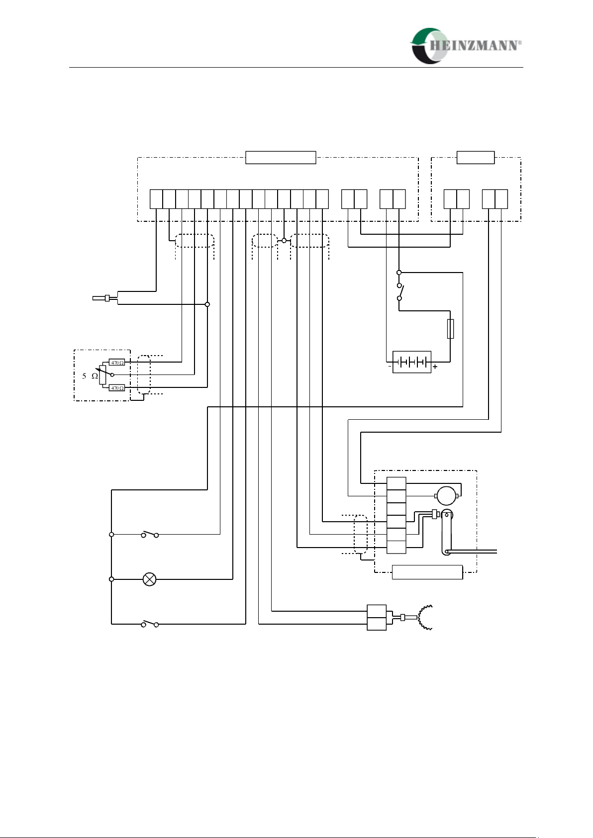
4 5 6 7 8 9 10 11 12 13 14 15 16 17 18 19 20 21
24V
C
B
D
A
E
A
B
M
DC .. 6-01
StG 6 .. 10 - 01
Actuator
Magnetic Pickup IA ..
Battery
Fuse
12 A
Governor
on
Control Unit
Temperature Sensor
Common Alarm
Run (open Engine Stop)
Increase Speed
Decrease Speed
22 23 24 25
CU-01
StG 16, 30, 40
11 Electrical connection
The electrical connection possibilities are depending on the variation of the control unit.
11.1 Connection for variation DG 6-01 (standard generator)
Digital Governor Basic System PANDAROS III 35
Fig. 15: Connection diagram for variation DG 6-01
11 Electrical connection
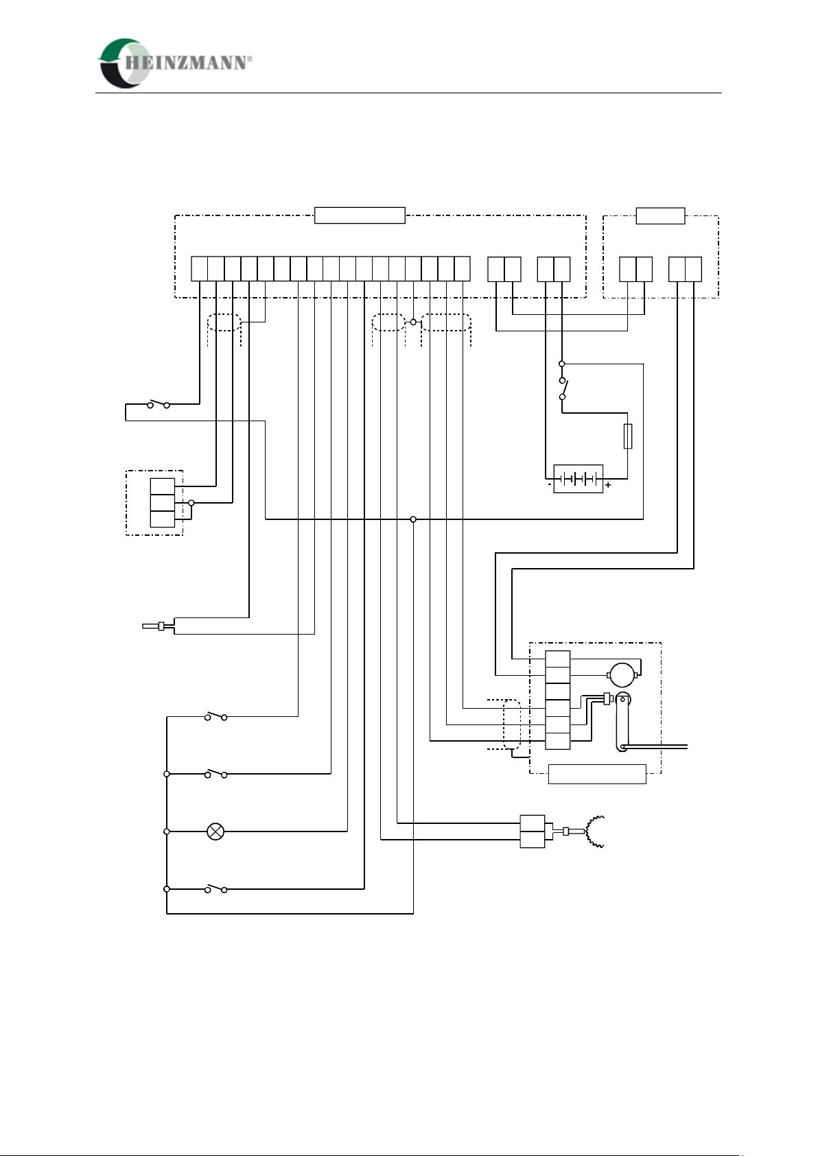
4 5 6 7 8 9 10 11 12 13 14 15 16 17 18 19 20 21
24V
C
B
D
A
E
A
B
M
DC .. 6-02
StG 6 .. 10 - 01
Actuator
Magnetic Pickup IA ..
Battery
Fuse
12 A
Governor
on
Control Unit
Common Alarm
Run (open Engine Stop)
Fixed Speed
22 23 24 25
CU-01
k
max.
min.
Temperature Sensor
Setpoint Potentiometer
cw
ccw
out
StG 16, 30, 40
11.2 Connection for variation DG 6-02 (standard general)
36 Digital Governor Basic System PANDAROS III
Fig. 16: Connection Diagram for Variation DG 6-02
11 Electrical connection
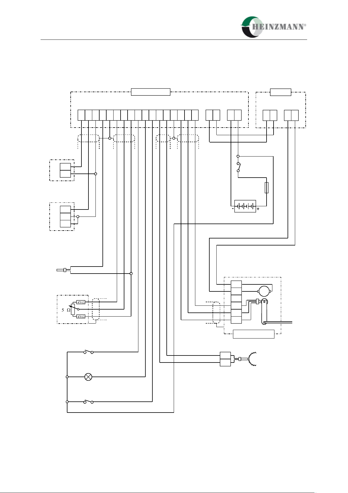
1 2 3 4 5 6 7 8 9 10 11 12 13 14 15 16 17
C
B
D
A
E
A
B
M
DC .. 6-03
StG 6 .. 10 - 01
Actuator
Magnetic Pickup IA ..
Control Unit
Temperature Sensor
Common Alarm
Run (open Engine Stop)
16
15
14
Load Measuring Unit
LMG 03-S2
Auxiliary Contact
Generator Breaker
Increase Speed
Decrease Speed
18 19 20 21
24V
Battery
Fuse
12 A
Governor
on
22 23 24 25
CU-01
StG 16, 30, 40
11.3 Connection for variation DG 6-03 (extended generator 1)
Digital Governor Basic System PANDAROS III 37
Fig. 17: Connection diagram for variation DG 6-03
11 Electrical connection
1 2 3 4 5 6 7 8 9 10 11 12 13 14 15 16 17 18 19 20 21
k
max.
min.
DC .. 6-04
Control Unit
Temperature Sensor
Setpoint Potentiometer
Selector Switch
Analogue Accessory Units/
Setpoint Potentiometer
Common Alarm
Run (open Engine Stop)
16
15
17
16 A
14
Synchronizer
SyG 02
Load Measuring Unit
LMG 03-S2
C
B
D
A
E
A
B
M
StG 6 .. 10 - 01
Actuator
Magnetic Pickup IA ..
24V
Battery
Fuse
12 A
Governor
on
22 23 24 25
CU-01
cw
ccw
out
StG 16, 30, 40
11.4 Connection for variation DG 6-04 (extended generator 2)
38 Digital Governor Basic System PANDAROS III
Fig. 18: Connection Diagram for Variation DG 6-04

11 Electrical connection
1 2 3 4 5 6 7 8 9 10 11 12 13 14 15 16 17 18 19 2021
k
max.
min.
DC .. 6-05
Control Unit
Oil Pressure Sensor
Boost Pressure Sensor
Temperature Sensor
Setpoint Potentiometer
Fixed Speed
Run (Engine Stop)
Common Alarm
C
B
D
A
E
A
B
M
StG 6 .. 10 - 01
Actuator
Magnetic Pickup IA ..
24V
Battery
Fuse
12 A
Governor
on
22 23 2425
CU-01
cw
ccw
out
StG 16, 30, 40
11.5 Connection for variation DG 6-05 (extended general)
Fig. 19: Connection Diagram for Variation DG 6-05
Digital Governor Basic System PANDAROS III 39

11 Electrical connection
It is not possible to use all offered signals at the same time, because some
inputs have to be assigned differently depending on the variation.
L1
Battery
Control Unit DC 6-01..05
Actuator
Setpoint Adjuster
Magnetic Pickup
Sensors
Switch Inputs
Error Messages
Communication
L2
L3
L4
L5
L6
L7
L10
+
-
Füllung Fuel Combustible
0
50
100
10
20
30
40
50
60
70
80
90
100
0
Generator-
management
DGM 02
CAN communication
L13
11.6 Harness
40 Digital Governor Basic System PANDAROS III
Fig. 20: Cable Designation

11 Electrical connection
The allowed length and necessary cross-sections of the cables to connect are as follows:
L 1 Power supply max. 15 m 2 x 2.50 mm²
L 2.1 Actuator feedback 3 x 0.75 mm², shielded
L 2.2 Actuator drive up to 10 m 2 x 2.50 mm²
over 10 - 20 m 2 x 4.00 mm²
L 3.1 Setpoint potentiometer 3 x 0.75 mm², shielded
L 3.2 4 - 20 mA input 2 x 0.75 mm²
L 3.3 0 - 5 V 2 x 0.75 mm², shielded
L 3.4 Synchronizer 2 x 0.75 mm², shielded
L 3.5 Load measuring unit 2 x 0.75 mm², shielded
L 4 Magnetic pick-up 2 x 0.75 mm², shielded
L 5.1 Temperature sensor 2 x 0.75 mm²
L 5.2 Boost sensor 2 x 0,75 mm²
L 5.3 Oil pressure sensor 2 x 0.75 mm²
L 6.1 Engine stop 1 x 0.75 mm²
L 6.2 Increase speed 1 x 0.75 mm²
L 6.3 Decrease speed 1 x 0.75 mm²
L 6.4 other switch functions 1 x 0.75 mm²
(the switches have to be supplied with battery plus)
L7 Error message 1 x 0.75 mm²
(the error lamp has to be supplied with battery plus, ground is switched)
L 13 CAN communication with DGM 02 2 x 0,14 mm², shielded
Digital Governor Basic System PANDAROS III 41

11 Electrical connection
42 Digital Governor Basic System PANDAROS III

12 Parametrization options
12 Parametrization options
The software for the HEINZMANN series Pandaros has been designed in a way that will
allow programming both at the HEINZMANN factory and by the engine manufacturer.
Since erroneous programming can cause considerable damages, full use should be made of the
level structure and the user masks.
As a principle, first programming should always be conducted by experienced personnel and
must be checked before first commissioning the engine. If possible, a HEINZMANN
specialist should be consulted when first programming is performed.
The following sections describe the possibilities of parametrizing the control unit:
12.1 Parametrization at the factory
During final inspection at the factory, the functionability of the unit is checked by a test
programme. If the operational data for the control unit is available, the test programme is
carried out using this data. It is then only the dynamics data and if need be the fuel
limitations and sensors that will have to be calibrated on the engine.
12.2 Parametrization with the Hand Held Programmer HP 03
All parametrization can also be done by means of the hand held programmer
‘Programmer 3’. This handy device is particularly suited for development and series
calibration as well as for servicing.
12.3 Parametrization with the PC
Parametrization can also be conducted using a PC and the comfortable HEINZMANN
software DcDesk 2000. As compared with the hand held programmer, it offers the great
advantage of having various curves graphically represented on the screen and being at the
same time able to introduce changes as well as of having time diagrams displayed without
an oscilloscope when commissioning the control unit on the engine. Furthermore, the PC
offers a better overview as the PC programme has a menu structure and allows to have
several parameters continuously displayed.
Besides, the PC programme permits to save and download the operational data to and from
diskettes.
Digital Governor Basic System PANDAROS III 43

12 Parametrization options
12.4 Parametrization with user mask
Principally, parametrization may be performed with the help of user masks that have been
provided by HEINZMANN or may conveniently be created by the user himself. Within a
user mask, only those parameters are accessible that are actually needed.
12.5 Transferring data sets
Once parametrizing a particular engine model and its application has been completed, the
data set can be saved (in the hand held programmer or on a floppy disk). For other
applications of the same kind the data set can then be downloaded into the respective
control units.
12.6 Assembly line end programming
This type parametrizing is used by the engine manufacturer during the test bench run when
the control unit is programmed in accordance with the engine requirements as laid down in
the order.
44 Digital Governor Basic System PANDAROS III

13 Starting the engine - brief instruction
Additional overspeed protection independent of the speed
controller is compulsory!
13 Starting the engine - brief instruction
13.1 Adjust clearance of magnetic pulse pick-up.
13.2 Check program with respect to relevant parameters: number of teeth, speed, etc.
13.3 Calibrate sensors and setpoint adjusters, if necessary.
13.4 Make autoadjustment of actuator.
13.5 Set point potentiometer in mid-position:
P - Gain to 50
I - Stability to 0
D- Derivative to 0
If the dynamic values have already been determined for an installation, they can be
programmed directly at this point.
13.6 Start engine and run it up to nominal speed using the set point potentiometer.
13.7 Increase gain (P-fraction) up to instability and reduce until stability is attained.
Increase stability (I-fraction) up to instability and reduce until stability is attained.
Increse derivative (D-fraction) up to instability and reduce until stability is attained.
With these values set, engine speed is to be disturbed briefly (e.g., by shortly
pressing the stop switch), and the transient oscillations are to be observed.
13.8 Check over the entire speed range.
If for maximum and minimum speed other values than the programmed ones should
result, this will be due to tolerances of the set point potentiometer. If the speed
derivation is not acceptable, it will be necessary to measure the setpoint source.
13.9 Gain-correction (P-correction) for gas engines resp. for variable speed governors
with larger speed ranges; adjust map if necessary.
13.10 Checking the remaining program items, e.g., starting fuel injection, ramp time, etc.
Digital Governor Basic System PANDAROS III 45


14 Download of manuals
14 Download of manuals
Technical manuals can be downloaded in pdf-format from our homepage:
www.heinzmann.com
If the desired manual should not be available there, send an e-mail to:
info@heinzmann.de
or write to:
HEINZMANN GmbH & Co. KG
Technische Redaktion
Am Haselbach 1
D-79677 Schönau/Germany
Please include the following information:
your name
name and address of your company
e-mail or address where you want the manuals to be sent to (if different from above)
item code (as on front page, bottom right) and title of the desired manual
or alternatively the technical data of your HEINZMANN equipment
We would be pleased to receive your comments about the contents and presentation of our
publications. Send your comments to the e-mail or address shown above please.
Digital Governor Basic System PANDAROS III 47
 Loading...