

Page 1
Magnetic-Inductive Flow Velocity Sensor
PIT
UMF2 (B)
Operating Manual
Page 1 of 14
Page 2

Heinrichs Messtechnik GmbH Operating Manual PIT-UMF2 (B)
Contents
1 IDENTIFICATION ................................................................................................................................................................ 3
1.1 Manufacturer/supplier ...................................................................................................................................................... 3
1.2 Product type ..................................................................................................................................................................... 3
1.3 Product name ................................................................................................................................................................... 3
1.4 Issue date ........................................................................................................................................................................ 3
1.5 Version No. ................................................................................................................................ ...................................... 3
2 APPLICATION .................................................................................................................................................................... 3
3 MODE OF OPERATION AND SYSTEM DESIGN ............................................................................................................... 4
3.1 Mode of operation ................................................................................................ ............................................................ 4
3.2 System design ................................................................................................................................................................. 4
3.2.1 Transmitter mounted on the sensor ................................................................ .................................................... 4
3.2.2 Remote installation of the transmitter ................................................................................................................. 5
3.2.3 Sensor versions PIT
4 CHARACTERISTICS .......................................................................................................................................................... 6
4.1 Accuracy .......................................................................................................................................................................... 6
4.2 Conductivity of fluid .......................................................................................................................................................... 6
4.3 Influence of ambient temperature ..................................................................................................................................... 6
4.4 Influence of medium temperature ..................................................................................................................................... 6
5 CONDITIONS OF USE ........................................................................................................................................................ 6
5.1 Installation conditions ....................................................................................................................................................... 6
5.1.1 Immersion depth of PIT-*** in the pipe ................................................................................................................ 6
5.1.2 Removal and installation under process pressure .............................................................................................. 7
5.1.3 Grounding ................................................................ .......................................................................................... 7
5.2 Use in hazardous areas ................................................................................................................................................... 7
5.3 Ambient conditions ........................................................................................................................................................... 7
5.3.1 Ambient temperature ranges .............................................................................................................................. 7
5.3.2 Storage temperature .......................................................................................................................................... 7
5.3.3 Climatic category ................................................................................................................................................ 7
5.3.4 Ingress Protection .............................................................................................................................................. 7
5.3.5 Shock resistance/vibration resistance ................................................................................................................. 7
5.4 Medium temperature and pressure ................................................................................................................................... 8
5.4.1 Direct mounted transmitter ................................................................................................................................. 8
5.4.2 Remote mounted transmitter .............................................................................................................................. 8
6 DIMENSIONS/WEIGHT ....................................................................................................................................................... 8
6.1 PIT-UMF2 (B) dimensional drawing for remote transmitter .............................................................................................. 8
6.2 PIT-** dimensional drawing with direct mounted transmitter UMF2 (B) ............................................................................. 9
7 POWER SUPPLY / ELECTRICAL CONNECTION ............................................................................................................ 10
8 CE-MARK10
9 STANDARDS AND DIRECTIVES, CERTIFICATES AND APPROVALS .......................................................................... 10
10 SAFETY INFORMATION .................................................................................................................................................. 10
10.1 Intended use .................................................................................................................................................................. 10
10.2 Installation, start-up and operating personnel ................................................................................................................. 10
11 PACKAGING, STORAGE AND TRANSPORT .................................................................................................................. 10
12 MAINTENANCE ................................................................................................................................................................ 10
13 RETURNING DEVICES FOR REPAIR AND SERVICE ..................................................................................................... 11
14 OPTIONS11
14.1 Removal and installation under process pressure .......................................................................................................... 11
14.2 PIT (Sensor) Ingress protection IP68 ............................................................................................................................. 11
14.2.1 Wiring diagram for remote installation .............................................................................................................. 12
15 DECONTAMINATION CERTIFICATE FOR DEVICE CLEANING ..................................................................................... 13
16 DECLARATION OF CONFORMITY .................................................................................................................................. 14
Page 2 of 14
Page 3

Operating Manual PIT-UMF2 (B) Heinrichs Messtechnik GmbH
Introduction
These Installation and Operating Instructions serve as a tool for the correct installation, operation and
maintenance of the device. They are a supplement to the PIT-UMF2 (B) device description. Read
theses manuals carefully before the device is installed and put into use. They do not include special
versions or applications.
All devices were thoroughly checked for order compliance and operability before delivery. Upon
receipt, please conduct a visual inspection of possible damage that may be identified as having
occurred during shipment. If you discover any defect, please contact our head office in Cologne or the
local sales office responsible for your area (see our Web site). Apart from a description of the error,
we will need the equipment type and serial number of the delivery.
Heinrichs Messtechnik shall not furnish guarantee for any repair work done without prior notice.
Unless otherwise agreed on, the rejected parts must be made available to us in case a claim is made.
1 Identification
1.1 Manufacturer/supplier
Heinrichs Messtechnik GmbH
Robert-Perthel-Str. 9 D-50739 Cologne
Phone +49 (221) 49708 - 0
Fax +49 (221) 49708 - 178
Internet: http://www.heinrichs.eu/
E-mail: mailto:[email protected]
1.2 Product type
Magnetic – inductive flow sensor based upon Faraday’s law of induction
1.3 Product name
PIT-UMF2 (B)
1.4 Issue date
13.02.2014
1.5 Version No.
File: PIT-UMF2 (B)_BA_02_EN_REV1.DOC
2 Application
The magnetic-inductive flow velocity sensor PIT-UMF2 (B) is used to measure or monitor the volume
flow of liquids with and without solids concentration and also other electrically conductive media while
minimizing pressure drops. The conductivity of the medium must be at least 20 µS/cm. Pressure,
temperature, density and viscosity do not affect the volume measurements. Smaller portions of solid
particles and small gas bubbles are also measured as part of the volume flow. A larger number of
solid particles or gas bubbles will lead to failures. Special electrodes are available for media that tend
to form greasy films or crusts.
Page 3 of 14
Page 4
Heinrichs Messtechnik GmbH Operating Manual PIT-UMF2 (B)
Fitting
Flange
Socket weld fitting
Lining
UMF2 transmitter
housing
Electrodes
Transmitter neck
3 Mode of Operation and System Design
3.1 Mode of operation
It was back in 1832 that Faraday suggested utilizing the principle of electromagnetic induction for
measuring flow velocities. His experiments in the Thames, though unsuccessful due to superimposed
polarization effects, are nonetheless regarded as the first ones in the field of magnetic-inductive flow
measurement.
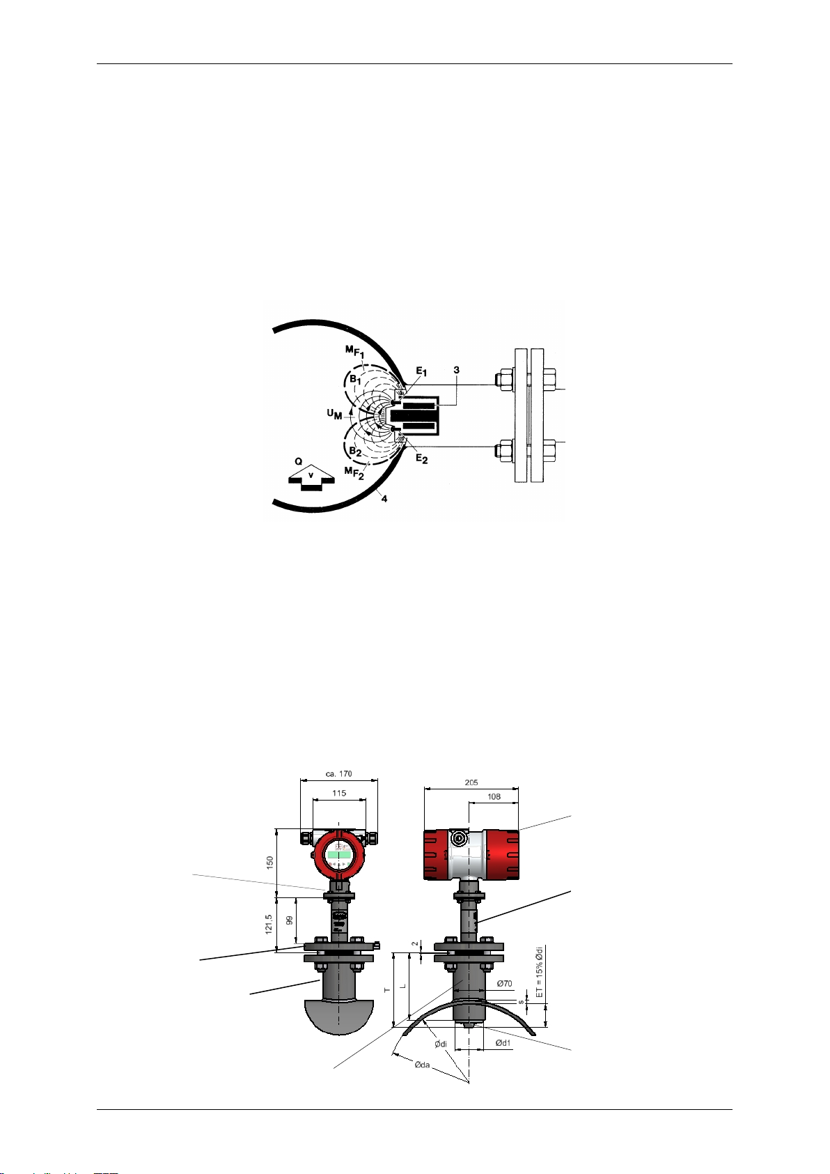
According to Faraday’s law of electromagnetic induction, an electrical field E is produced in a
conductive liquid moving through a magnetic field B at a velocity v in accordance with the vector
product E = [v x B]. A liquid at flow velocity v and a flow rate Q flows through a meter tube (4),
producing a measuring-circuit voltage Um at the two electrodes (E1 and E2) at right angles to the
direction of flow and the magnetic field B generated by the field coils (3). The size of this measuringcircuit voltage is proportional to the mean flow velocity and thus the volume flow rate.
3.2 System design
The magnetic-inductive PIT-UMF2 (B) flow measurement system consists of a sensor (PIT), which
picks up an induced measuring signal from the medium flowing through the pipe, and a transmitter
(UMF2 (B)), which transforms this signal in standardized output signals (4-20 mA or pulses).
The PIT-*** sensor can be operated with all transmitters for magnetic-inductive flow meters
manufactured by Heinrichs Messtechnik. The sensor is installed in the pipe while the transmitter is
mounted directly on the sensor or separately on the outside, depending on the equipment design.
3.2.1 Transmitter mounted on the sensor
This type of construction ensures easy and trouble-free installation
Page 4 of 14
Page 5
Operating Manual PIT-UMF2 (B) Heinrichs Messtechnik GmbH
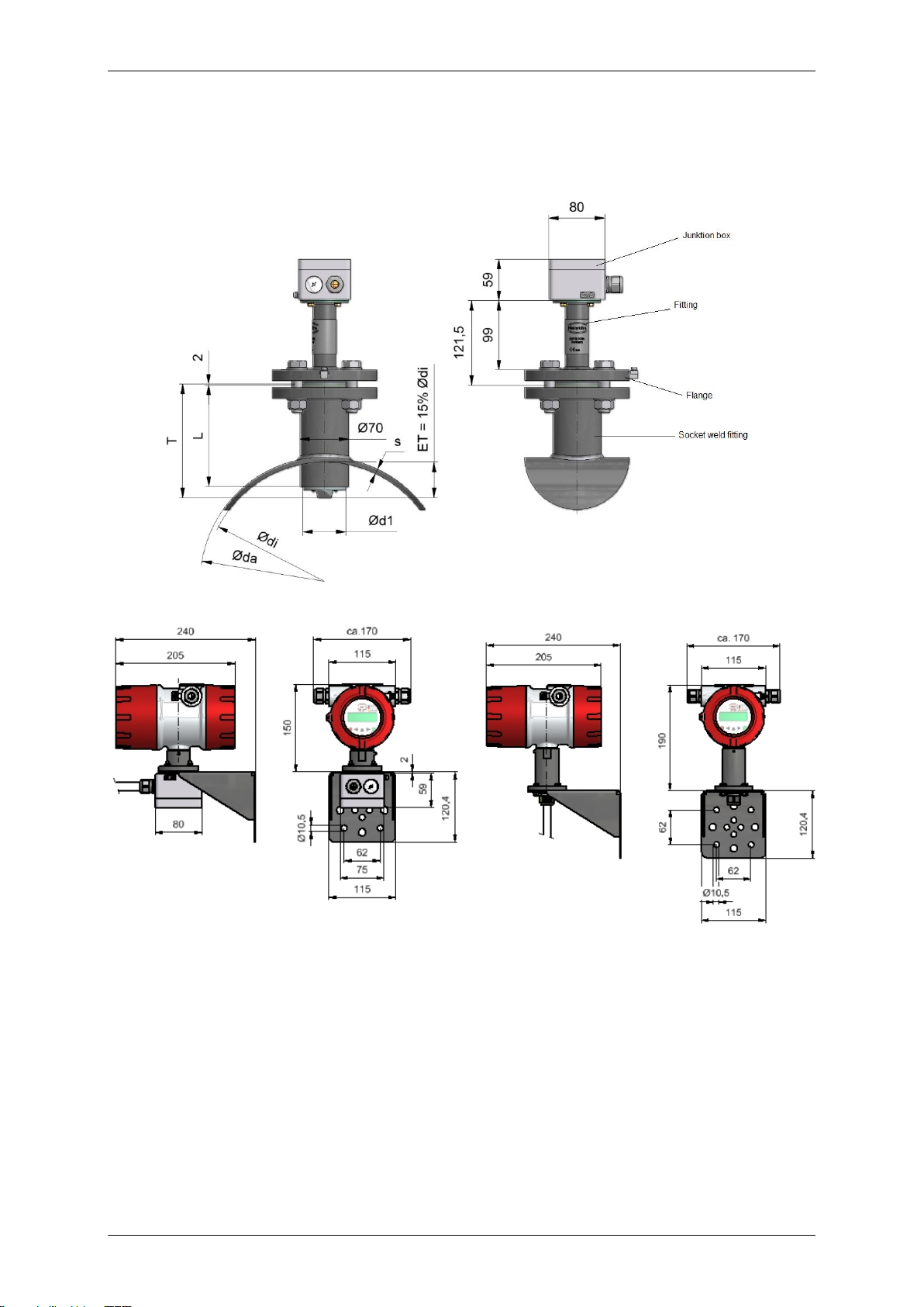
Remote transmitter with terminal connection box,
(For cable length longer than 10 m)
Remote transmitter with direct connected cable to transmitter,
(For cable length of max. 10 m)
(All dimensions in mm)
3.2.2 Remote installation of the transmitter
Heinrichs Messtechnik recommends this type of installation when there is little space or the medium
temperatures are high. The sensor and the transmitter are connected by a field coil and an electrode
cable. The electrode cable must be shielded and protected against disturbing interferences.
3.2.3 Sensor versions
PIT-S Wetted parts stainless steel / hastelloy / PTFE,
Transmitter neck connection flange stainless steel
PIT-A Wetted parts PFA / hastelloy,
Transmitter neck connection flange stainless steel
PIT-U Version with retraction device
Page 5 of 14
Page 6
Heinrichs Messtechnik GmbH Operating Manual PIT-UMF2 (B)
4 Characteristics
4.1 Accuracy
1.5 % of measured value plus 0.5 % of URV
4.2 Conductivity of fluid
20 µS/cm
4.3 Influence of ambient temperature
Pulse output 0, 05% pro 10K
Current output 0, 1% pro 10K
4.4 Influence of medium temperature
None
5 Conditions of use
5.1 Installation conditions
Disturbing elements (e.g. shut-off and control valves) are to be arranged downstream from the sensor.
If this is not possible, flow conditioners must be installed so that no vortexes can reach the pipe
section of the sensor. The mounting location in the pipe system should be selected so that the sensor
is continually filled with the medium. This requirement can be met by using drains and check valves.
.
In order to stay within the indicated accuracy, the installation must be performed according to
EN 29104 "Measurement of Fluid Flow in Closed Conduits – Methods of Evaluating the Performance
of Magnetic-Inductive Flow meters." Based on this standard, the minimum straight run of pipe ahead
of the inlet must be 10 pipe diameters (> 10 x DN) and 5 pipe diameters following the outlet (> 5 x DN)
[DN = nominal diameter of pipe].
In order to prevent serious measuring errors when the pipe is partially filled or when there are gas
bubbles or sediment deposits, the mounting position described above should be chosen.
The limits for the product and ambient temperature must be met at the mounting location. Corrosive
atmospheres must be avoided. Please also take into account the space requirement for a possible
removal of the device.
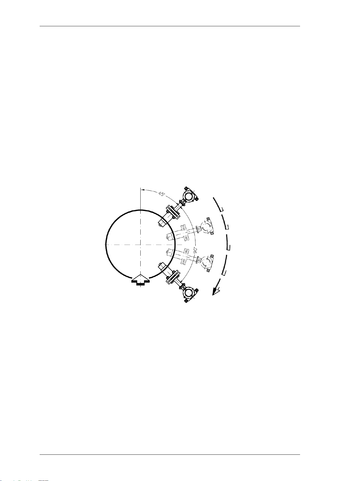
5.1.1 Immersion depth of PIT-*** in the pipe
In order to suppress the influence of the flow profile as much as possible, the depth of immersion of
the sensor head in the pipe must be 15 % of the inside diameter of the pipe. The socket weld fitting
must not cover the top of the sensor head and must be shortened if necessary.
Page 6 of 14
Page 7
Operating Manual PIT-UMF2 (B) Heinrichs Messtechnik GmbH
Caution:
Ingress protection IP68 is only achieved if suitable and tightly screwed down cable
glands or conduits are used. If the cable glands are only tightened manually water may
leak into the terminal compartment in the housing.
Danger:
Particular care must be taken if the window in the housing becomes fogged over or
discolored because moisture, water or product might seep through the wire sheath into
the terminal compartment in the housing!
Warning:
Electromagnetic compatibility is only achieved if the electronics housing is closed.
Leaving the enclosure open can lead to electromagnetic disturbances.
5.1.2 Removal and installation under process pressure
For easy removal and installation under pressure, a special retraction device is available. When using
this device, the sensor head must not be damaged by closing the valve.
For details, see the Additional Operating Instructions for Removal and Installation the meter under
process pressure Additional Operating Instructions PIT-Druck_BA_0X_eng.doc (see also Section 14
"Options").
5.1.3 Grounding
For safety reasons and to ensure faultless operation of the magnetic-inductive flow meter, earthing of
the flow sensor is important. In accordance with VDE 0100, Part 540, the earthing connections must
be connected to the grounding conductor. To avoid false measurement, the ground potential must be
identical to the ground potential of the medium.
When using insulated and lined pipes or plastic pipes, the metrological grounding of the medium for
PIT-S (SS) is carried out via the wetted part of the sensor head.
All wetted parts of PIT-A (PFA) are coated with PFA. Therefore it is not possible to ground the medium
via the housing parts. In this case make sure that the PIT-A sensor will be supplied an earthing. If the
sensor does not have an earthing electrode ensure that a suitable earthing disc will be used.
5.2 Use in hazardous areas
The flow meters PIT-…/UMF2 (B) are not intended for use in hazardous areas.
5.3 Ambient conditions
5.3.1 Ambient temperature ranges
-20°C to +60°C, below 0°C the readability of the LCD is limited
5.3.2 Storage temperature
-25°C to +60°C
5.3.3 Climatic category
In accordance with IEC 654-1
Not weather-protected Class D locations exposed directly to open-air climate
5.3.4 Ingress Protection
PIT standard sensor: IP65, option: IP68
UMF2 (B) standard housing IP68 (NEMA 6P)
5.3.5 Shock resistance/vibration resistance
The meter should be protected from extreme shocks and vibrations, which could cause damage.
Page 7 of 14
Page 8
Heinrichs Messtechnik GmbH Operating Manual PIT-UMF2 (B)
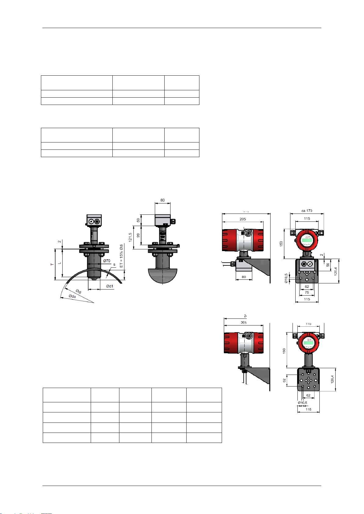
Version
Medium
temperature
Pressure
PIT-S (SS / PTFE)
-20°C to 80°C
16 bar
PIT-A (PFA)
-20°C to 80°C
40 bar
Version
Medium
temperature
Pressure
PIT-S (SS / PTFE)
-40°C to100°C
16 bar
PIT-A (PFA) standard
-40°C to 140°C
40 bar
Version
DN T Ød1
L
PIT-A (PFA)
150-600
163mm
62mm
145mm
PIT-S (SS / PTFE)
150-600
163mm
60,3mm
145mm
PIT-S (SS / PTFE)
700-1200
263mm
60,3mm
170mm
PIT-S (SS / PTFE)
1400-2000
363mm
60,3mm
170mm
Transmitter with term. conn. box
Transmitter with directly connected
cable (up to 10 m)
IP 68 terminal connection box
57x75x110 mm
5.4 Medium temperature and pressure
5.4.1 Direct mounted transmitter
5.4.2 Remote mounted transmitter
6 Dimensions/weight
6.1 PIT-UMF2 (B) dimensional drawing for remote transmitter
(All dimensions in mm)
Weight: 3.6 kg
DN: Nominal Diameter
T: Length of sensor
Ød1: Diameter of sensor
L: Length of socket weld fitting
ET: Immersion depth in % of pipe diameter
Page 8 of 14
Page 9
Operating Manual PIT-UMF2 (B) Heinrichs Messtechnik GmbH
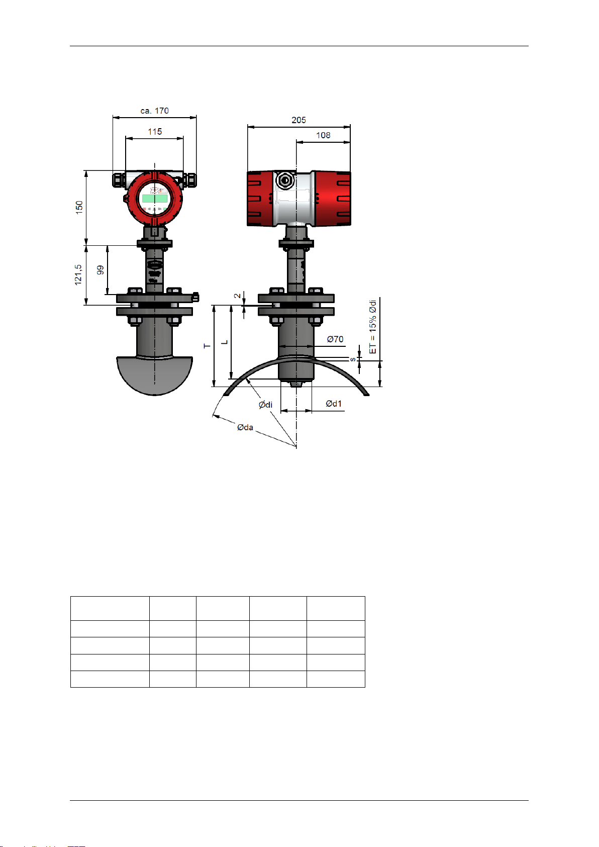
Version
DN T Ød1
L
PIT-A (PFA)
150-600
163mm
62mm
145mm
PIT-S (SS / PTFE)
150-600
163mm
60,3mm
145mm
PIT-S (SS / PTFE)
700-1200
263mm
60,3mm
170mm
PIT-S (SS / PTFE)
1400-2000
363mm
60,3mm
170mm
6.2 PIT-** dimensional drawing with direct mounted transmitter UMF2 (B)
(All dimensions in mm)
Weight: 5.5 kg
DN: Nominal Diameter
T: Length of sensor
Ød1: Diameter of sensor
L: Length of socket weld fitting
ET: Immersion depth in % of pipe diameter
Page 9 of 14
Page 10

Heinrichs Messtechnik GmbH Operating Manual PIT-UMF2 (B)
7 Power supply / electrical connection
See name plate or Operating Instructions of the corresponding transmitter.
8 CE-Mark
The measuring system complies with the legal requirements of the following EU Directives: Low
Voltage Directive 2006/95/EC, Electromagnetic Compatibility Directive 2004/108/EC
Heinrichs Messtechnik confirms compliance with the directives by attaching the CE mark to the device.
9 Standards and directives, certificates and approvals
Certified to DIN-EN-ISO 9001:2008
Production in accordance with AD2000 guidelines
TÜV approval for welding requirements in accordance with EN 3834-2
General standards and directives
EN 61010 – Safety requirements for electrical measuring, control and laboratory devices
EN 60529:2010 – Degrees of protection through housing (IP code)
EMC Directive 2004/108/EC
EN 61000-6-2:2005 immunity for industrial environments
EN 61000-6-3:2007+A1:2011 emissions residential environments
EN 55011:2009+A1:2010 group 1, class B (emitted interference)
10 Safety information
10.1 Intended use
The PIT-UMF2 (B) flow meter may be used only for flow measurements of fluids whose conductivity
exceeds 20µS/cm. The manufacturer shall not be liable for damages that may result from unintended
or inappropriate use.
When dealing with an aggressive medium, clarify the material durability of all wetted parts.
10.2 Installation, start-up and operating personnel
Only trained specialists authorized by the system operator may carry out the installation, electrical
installations, start-up maintenance and operation. They must read and understand the operating
manual and follow its instructions. Basically, the national conditions and provisions must be followed.
11 Packaging, storage and transport
Carefully unpack the device to avoid damaging it.
Storage and installation must be done in a clean and dry room so that contamination – especially of
the interior of the fitting – is avoided. The ambient temperature ranges must be observed.
With the help of the delivery note enclosed in the packaging, check whether all technically relevant
data coincide with your requirements.
When transporting the device to a remote mounting location, we recommend that you reuse the
factory-issued packaging and the transport protection.
12 Maintenance
The device requires no maintenance if used according to its intended purpose. Cleaning might be
necessary due to deposits and dirt on the electrodes or the sensor head.
Page 10 of 14
Page 11
Operating Manual PIT-UMF2 (B) Heinrichs Messtechnik GmbH
13 Returning devices for repair and service
Note: In accordance with the applicable German waste disposal legislation, the owner/client is
responsible for the disposal of special waste and hazardous materials. Consequently, all devices sent
to us for repair must be free of any hazardous materials. This also applies to possible hollow spaces
and fissures in the devices.
If repair is necessary, confirm the above-mentioned item in writing (please use the form in the
Appendix). If hazardous materials remain in or on the device after it has been returned, Heinrichs
Messtechnik shall be authorized to remove them at the client’s expense without further inquiry.
14 Options
14.1 Removal and installation under process pressure
In some cases it might be necessary to remove and reinstall the PIT sensor head for cleaning when
the pipe is under process pressure. A special retraction device can be used for this purpose.
When using this device, it is important to ensure that the sensor head will not be damaged by closing
the valve. For a detailed description of this process, see the Additional Operating Instructions (PITDruck_BA_03_eng) for removal and installation the meter under process pressure (Section 5.1.2).
14.2 PIT (Sensor) Ingress protection IP68
A special version of PIT is available with the IP 68 degree of protection. This version is equipped with
a special terminal box, special cable glands and a special cable. The length of the cable must be
specified when placing the order. The terminal box does not need to be opened during the
installation. If this should be necessary, the cover must be remounted carefully. This is the only way to
ensure the IP 68 degree of protection.
The standard immersion depth is 5 m. (Material of term. connection box Aluminum)
Longer immersion depth up to 25 m with filling of the term. Connection box with special
sealing Compound „GHB1” and with factory connected cable at the sensor terminal
connection box. (Option)
Material of term. connection box: Aluminum
IP 68 version - seawater resistant: material of term. connection box : PE glass fiber reinforced,
black 57x75x110 mm (Option)
Page 11 of 14
Page 12
Heinrichs Messtechnik GmbH Operating Manual PIT-UMF2 (B)
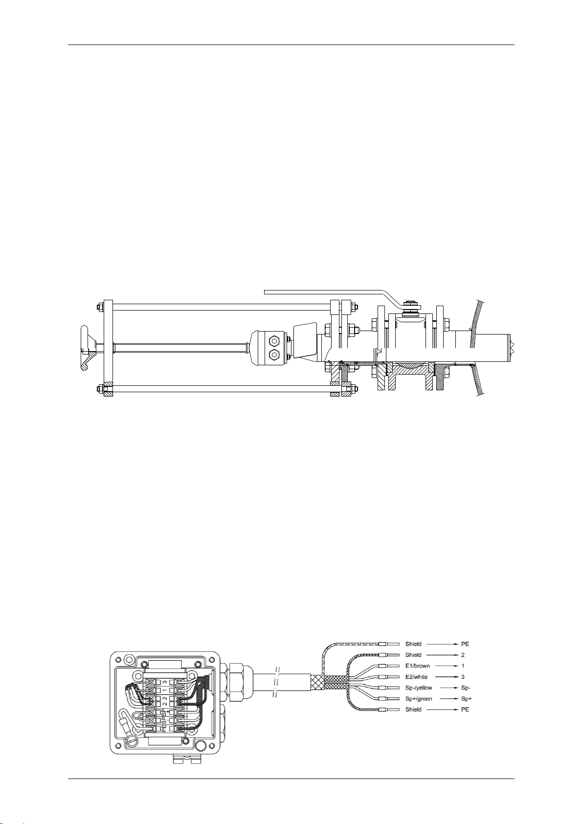
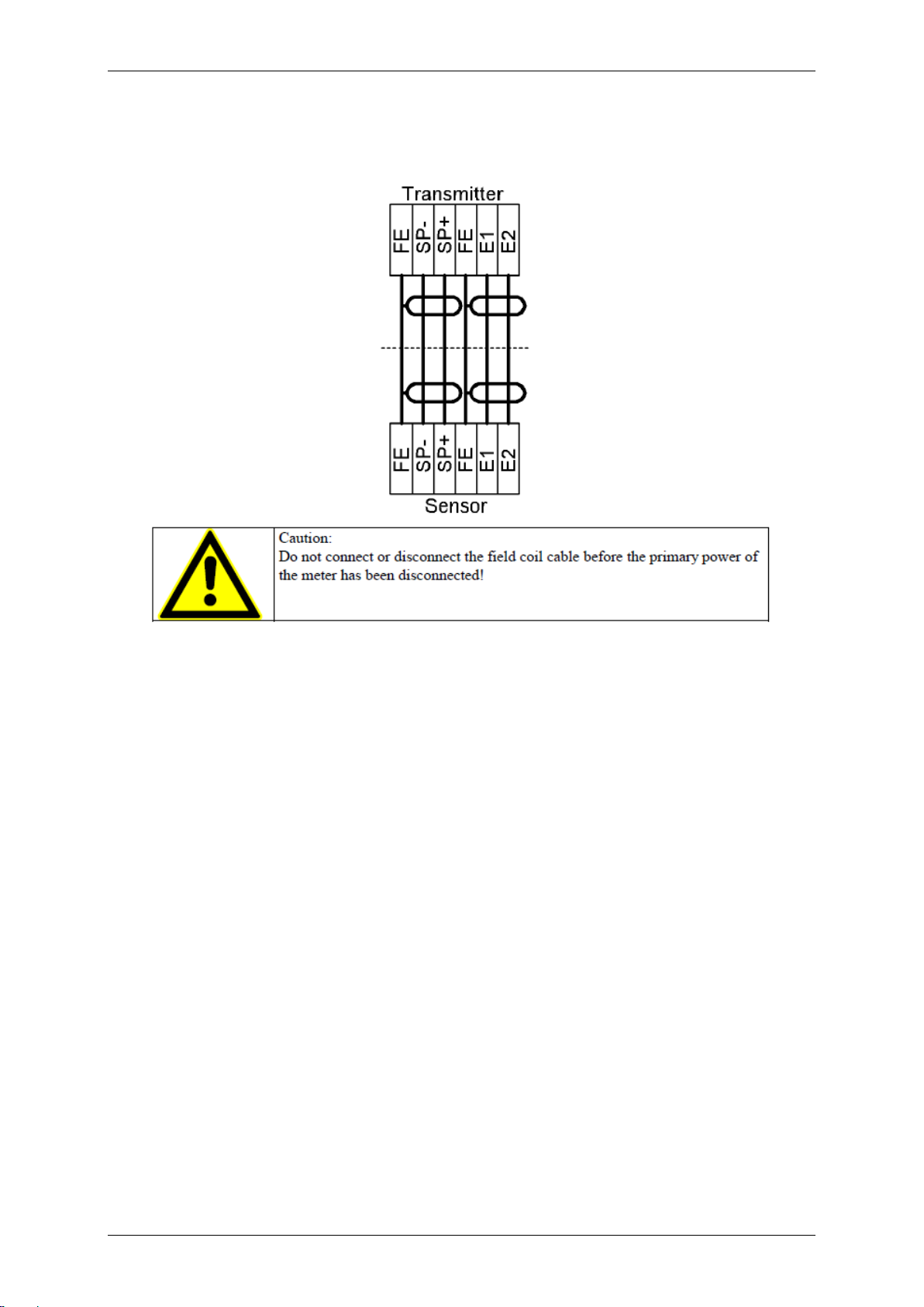
14.2.1 Wiring diagram for remote installation
The outer shield hast o be connected to the metalized cable glands at both ends. The inner shields
are connected to each other and are plugged into the terminal with the label “Schirm / shield”.
For more details on wiring see Instruction Manual UMF2 (B)(b)_BA_01_eng.pdf
Page 12 of 14
Page 13

Operating Manual PIT-UMF2 (B) Heinrichs Messtechnik GmbH
15 Decontamination certificate for device cleaning
Company: ............................... City: ...................................
Department: ......................... Name: ..............................
Tel. No.: .............................
This flow meter
Type PIT- .........
was operated using the measured medium..................................................................
Since this measured medium is dangerous in water/poisonous/corrosive/flammable,
we have
- checked that all hollow spaces of the device are free of these materials*
- neutralized and flushed all hollow spaces of the device*
*cross out what is not applicable.
We hereby confirm that in resending the device no danger to persons or the
environment is posed by the residual measured substance.
Date: ............................. Signature: ...........................
Stamp
Page 13 of 14
Page 14

Konformitätserklärung
Declaration of conformity
Heinrichs Messtechnik GmbH, Robert-Perthel-Straße 9, 50739 Köln
erklärt in alleiniger Verantwortung, dass das Produkt
declares in sole responsibility that the product
magnetisch induktiver Messumformer in Kombination mit Sensor der Baureihe
electromagnetic flowmeter transmitter in combination with electromagnetic flow meter sensor
Typ / type
mit den Vorschriften folgender Europäischer Richtlinien übereinstimmt:
conforms with the regulations of the European Directives:
EMV-Richtlinie 2004/108/EG, EMC Directive 2004/108/EC
Niederspannungsrichtlinie 2006/95/EG, Low Voltage Directive 2006/95/EC
EN 61000-6-2:2005 Störfestigkeit Industriebereich / immunity industrial environment
EN 61000-6-3:2007+A1:2011 Störaussendung Wohnbereich / emission residential, commercial
EN 55011:2009+A1:2010 Funkstörungen / Radio-frequency disturbance characteristics
EN 61010-1:2010 Sicherheitsbestimmungen für elektrische Mess-, Steuer-, Regel- Laborgeräte /
Safety requirements for electrical measuring, control and laboratory devices
Name und Anschrift der benannten Stellen der QS-Überwachung, Name and address of the Notified Bodies
DEKRA EXAM GmbH
Carl-Beyling-Haus
Dinnendahlstraße 9
D-44809 Bochum
Identifikationsnummer RL 94/9/EG: 0158
Köln, 16.03.2016
PIT& UMF2(b)
Frank Schramm
(Geschäftsführung / General Management)
 Loading...