

Page 1
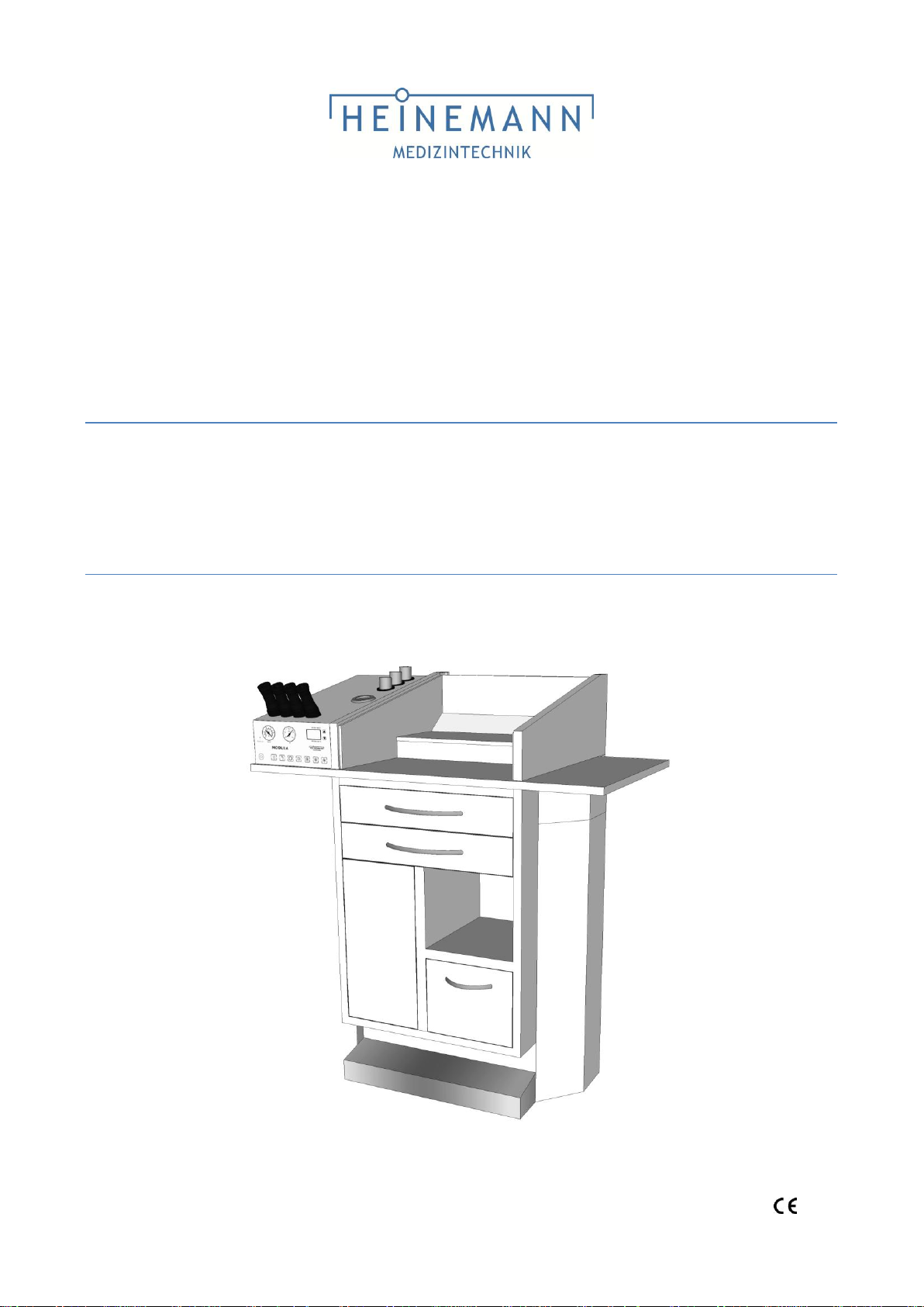
USER`S MANUAL
ENT Diagnostic & Treatment Unit
MODULA Paris
0482
Page 2

G. Heinemann Medizintechnik GmbH
MODULA Paris
2
User`s manual MODULA Paris (HM_TK_GA-Paris_28062013_06_EN)
Page 3
G. Heinemann Medizintechnik GmbH
MODULA Paris
3
User`s manual MODULA Paris (HM_TK_GA-Paris_28062013_06_EN)
Introduction
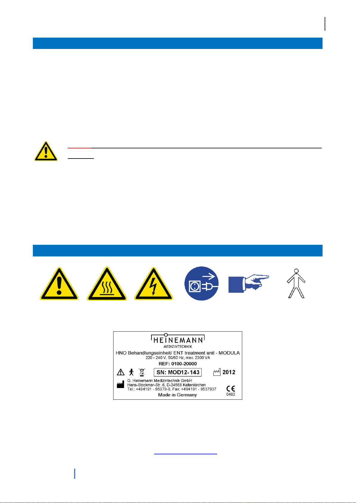
Attention!
Attention! Hot!
Dangerous
voltage!
Pull plug
before
opening!
Note
Appliance type
B
Type label for MODULA units
Thank you for choosing to purchase the MODULA Paris treatment unit. Its modular design allows the unit to
be used for a wide range of applications in every practice or hospital.
These operating instructions contain information on operation, care and simple maintenance tasks. All of the
information on the following pages relates to a MODULA unit fitted with all optional items of equipment.
Descriptions for items which are not installed are therefore non-binding. If you would like to add specific
optional equipment to your MODULA unit, please contact us on: +49 4191-95379-0
Caution! Before using the treatment unit, please read these operating instructions
carefully.
These operating instructions were produced by G. Heinemann Medizintechnik GmbH and have been
checked for accuracy. They do not, however, claim to be exhaustive. All information may be amended
without prior notification.
No part of these operating instructions may be copied or broadcast by any method or means, whether
electronic or mechanical, without the express written approval of G. Heinemann Medizintechnik GmbH.
Signs and symbols
Manufacturer:
G. Heinemann Medizintechnik GmbH, Leibnizstraße 13-15, D-24568 Kaltenkirchen
Phone: +49 4191-95379-0, Fax: +49 4191-9537937, E-mail: [email protected]
Web: www.heinemann-ent.de
Page 4

G. Heinemann Medizintechnik GmbH
MODULA Paris
4
User`s manual MODULA Paris (HM_TK_GA-Paris_28062013_06_EN)
Contents
Introduction ......................................................................................................................................................... 3
Signs and symbols .............................................................................................................................................. 3
1 General notes for usage ............................................................................................................................. 5
1.1 Purpose of the device ........................................................................................................................ 5
1.2 Indications / Contraindications ........................................................................................................... 6
2 Delivery and unpacking .............................................................................................................................. 7
2.1 Returns .............................................................................................................................................. 7
2.2 Connecting and setting up the unit .................................................................................................... 7
3 Safety instructions ...................................................................................................................................... 8
4 Note on operation ....................................................................................................................................... 9
4.1 Main power switch ............................................................................................................................. 9
4.2 Mirror heater .................................................................................................................................... 10
4.3 Suction with manual emptying (option) ............................................................................................ 10
4.4 Suction with „Sekretomatik“ system (option) ................................................................................... 11
4.5 Cold light sources (option) ............................................................................................................... 12
4.6 Compressed air unit (option) ........................................................................................................... 13
4.7 Ear irrigation with water connection (option) ................................................................................... 13
4.8 Ear irrigation with autonomous water system (option) .................................................................... 14
4.9 Tube rinsing system (option) ........................................................................................................... 15
4.10 Tube rinsing system with disinfectant (option) ................................................................................. 15
4.11 Laryngoscope/ endoscope holders (option) .................................................................................... 16
4.12 Heated instrument tray (option) ....................................................................................................... 16
5 Maintenance and repair ............................................................................................................................ 17
5.1 Cleaning ........................................................................................................................................... 17
5.2 Changing the bacteria filter .............................................................................................................. 18
5.3 Emptying the suction reservoir ........................................................................................................ 18
5.4 Replacing the waste bag ................................................................................................................. 19
5.5 Optical cable .................................................................................................................................... 19
5.6 Replacing the halogen lamp ............................................................................................................ 19
5.7 Cleaning the water filter ................................................................................................................... 20
5.8 Replacing fuses ............................................................................................................................... 22
6 Hygiene ..................................................................................................................................................... 23
7 Guarantee ................................................................................................................................................. 24
8 Annex ........................................................................................................................................................ 25
8.1 Technical details .............................................................................................................................. 25
8.2 Figures ............................................................................................................................................. 25
8.3 Consumables & spare parts ............................................................................................................ 27
Page 5
G. Heinemann Medizintechnik GmbH
MODULA Paris
5
User`s manual MODULA Paris (HM_TK_GA-Paris_28062013_06_EN)
1 General notes for usage
The MODULA treatment unit may only be used by persons offering a guarantee of correct usage of the
device and who have been instructed in its use. Instruction may only be given by authorized G. Heinemann
Medizintechnik GmbH personnel.
As for all highly developed technical devices, care and regular maintenance of the treatment unit is very
important. You should also ensure that you are thoroughly familiar with the functions and specifications of
the device.
Caution! Before using the device in actual practice, it is essential that you thoroughly
familiarise yourself with the functions of the treatment unit.
Should you require further information, please contact our sales and service office. Telephone: +49 419195379-0
Caution! G. Heinemann Medizintechnik accepts no liability for the safety or proper
function of the device where it has been installed, extended or repaired by persons who
have not been authorised by the manufacturer or if the device is used incorrectly or other
than as described in the operating instructions.
1.1 Purpose of the device
The product is a Class IIa medical device as defined by Directive 93/42/EEC. The product is to be used for
human medical purposes only. The product consists of a metal body and additional options.
The treatment unit is intended for diagnosis and treatment of ENT conditions. Depending on the equipment
installed, the unit may include ear irrigation, compressed air, suction and cold light.
Operation of the unit requires a power supply and, depending on the equipment installed, water and
drainage connections. Specifications for these can be found in appendix.
Page 6

G. Heinemann Medizintechnik GmbH
MODULA Paris
6
User`s manual MODULA Paris (HM_TK_GA-Paris_28062013_06_EN)
1.2 Indications / Contraindications
Ear irrigation:
Cleaning the auditory canal
Vestibular investigations (caloric stimulation of the vestibular system)
Suction:
Suctioning blood (emergency, haemorrhage, post-op)
Suctioning wound exudate post-op
Suctioning of secretions
Cleaning the auditory canal
Cleaning the nostrils and sinuses
Oral suctioning (tonsilar calculi/pus)
Compressed air:
Application of medications (nebulisation), including to surfaces
Performing politzerisation
Light sources:
Illumination during endoscopy, microscopy, investigations involving a
headlight
Ear irrigation:
Perforated eardrum
Cholesteatoma
Chronic otitis media
Episodes of acute vertigo
Otitis externa
Tympanoplasties
Compressed air:
Intracranial injuries
Orbit (eye socket) injuries
CSF fistula
Following middle ear surgery
Sinusitis
Purulent rhinorrhoea
Petrous fracture
The treatment unit is for use in all preliminary examinations of the ear, nose and throat in hospitals or
medical practices. The following table provides an overview of potential indications and contraindications:
Should you require any further information, please contact our sales and service office. Telephone: +49
4191-95379-0
Page 7

G. Heinemann Medizintechnik GmbH
MODULA Paris
7
User`s manual MODULA Paris (HM_TK_GA-Paris_28062013_06_EN)
2 Delivery and unpacking
Please examine the treatment unit for any damage during transportation and check that all items are present
immediately on receipt. Check the enclosed delivery note. Failure to do so may result in loss of the right to
replacement. Some accessories are packed within the treatment unit.
2.1 Returns
Any missing parts or incorrect functionality should be reported to the supplier of the treatment unit together
with the invoice, serial number and a precise description of the fault, immediately!
2.2 Connecting and setting up the unit
Caution! G. Heinemann Medizintechnik accepts no liability for the safety or proper
function of the device where it has been installed, extended or repaired by persons who
have not been authorised by the manufacturer.
The treatment unit must not be used in areas in which there is a danger of explosion.
A service technician will connect and set up the treatment unit for use after delivery.
Please ensure that building water and power connectors are properly installed by your fitter. Further
information can be obtained from our service department.
A water and power supply connection diagram follows. The dimensions for water connections given in the
diagram below must be adhered to.
Our service technician / medical products advisor will instruct you on operation after installing the device.
Page 8

G. Heinemann Medizintechnik GmbH
MODULA Paris
8
User`s manual MODULA Paris (HM_TK_GA-Paris_28062013_06_EN)
3 Safety instructions
The device must be directly connected to a properly installed earthed socket. The supply voltage
must conform to the voltage indicated on the type label. Rooms used for medical purposes must be
equipped with residual current circuit breakers.
Ensure that the device is functioning correctly and in a proper condition before each use. Any
damaged cables or tubes must be replaced immediately. Malfunctions must be reported to the
technical service department without delay.
Avoid spilling liquids or placing used (contaminated) instruments on the treatment unit. If your unit
has a dish for discarded instruments, ensure that instruments are discarded such that no liquids
enter the treatment unit. For further hygiene and care instructions, please refer to our hygiene
booklet.
Please be aware of the risk of crushing injuries from moving parts.
Do not place used (contaminated) instruments on the unit. Please observe the instructions given in
the hygiene booklet.
The environmental conditions specified in the technical data (section 8.1) must be adhered to.
The suction unit on MODULA units is intended for suctioning liquids in medical areas only. Do not
suction explosive, inflammable or corrosive gasses or liquids. The unit is for use in rooms used for
medical purposes only, but must not be used in areas in which there is a danger of explosion.
The MODULA unit meets the standards for susceptibility to interference set out in EN 60601-1-2
(EMC of medical electrical equipment). The MODULA unit may not be used in conjunction with
devices which do not conform to the standards EN 60601-1 "Medical Electric Equipment" and EN
60601-1-2 "Electromagnetic compatibility (medical electric equipment)".
The warranty does not cover loss or damage occurring as a result of the use of third party accessories or
consumables. Heinemann Medizintechnik is not liable for bodily injury or damage to property in the event
that parts other than original Heinemann parts are used, in the event of failure to observe the instructions for
use given in these operating instructions or if the device has been assembled, reinstalled, modified,
extended or repaired by persons not authorised by Heinemann.
Page 9
G. Heinemann Medizintechnik GmbH
MODULA Paris
9
User`s manual MODULA Paris (HM_TK_GA-Paris_28062013_06_EN)
4 Note on operation
The treatment unit should be inspected and its proper function
checked daily prior to being used with patients (tubes, cable
connectors, display instruments, cleanliness, etc.)
Power and water connections for the treatment
unit must be secure!
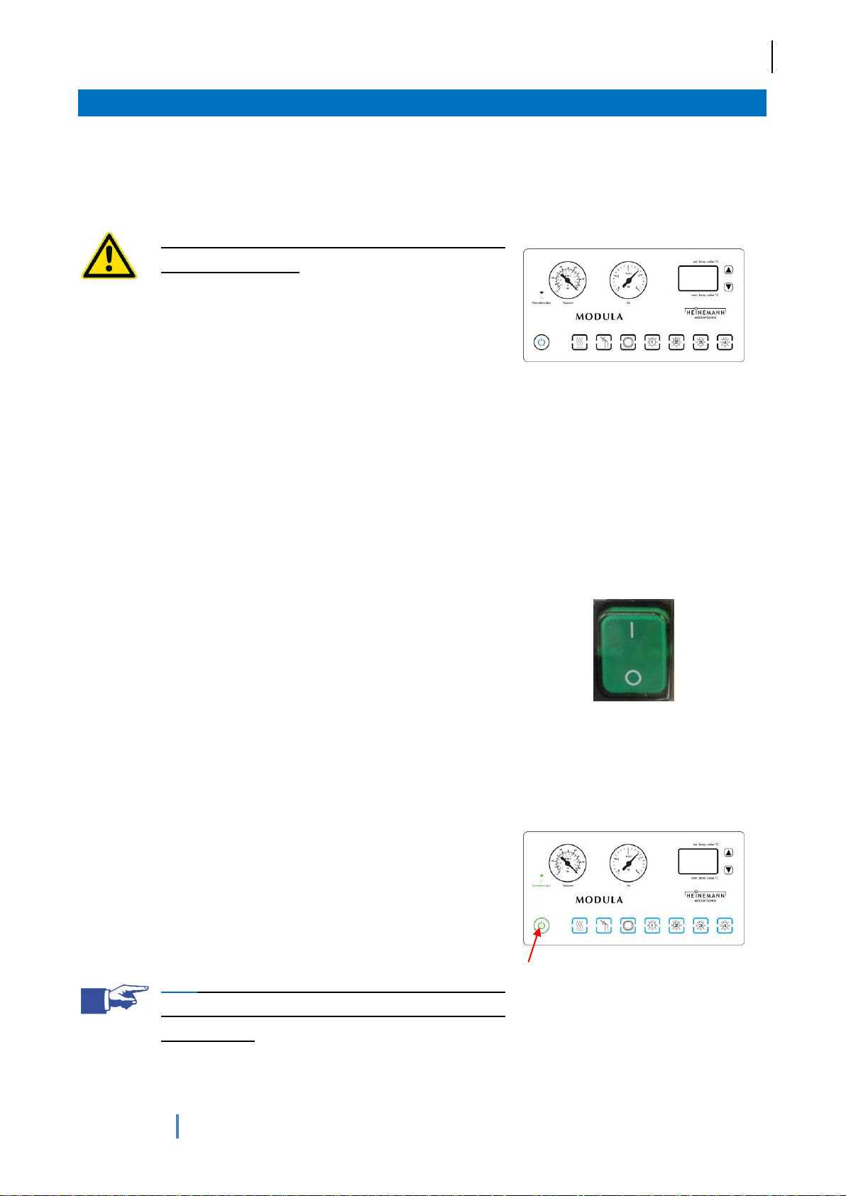
Note for units with a glass display: the unit is operated using a
touch-sensitive glass surface, which covers a set of sensors. The
sensors transform touches of the sensor field into a switching
signal. The sensors react to touch with a short delay (in order to
avoid unintended touches) and activate the relevant function.
Activation of a function is signalled with a click. After activating a
function, the colour of the sensor field changes from blue to green.
It remains blue for as long as the function remains active.
Fig. 1: Glass display
4.1 Main power switch
The treatment unit is switched on via the main power switch (fig. 2)
and is then ready to use.
Models with glass display only: on the Europa and Paris models,
the main power switch is located on the rear of the control panel.
Pressing the main power switch places the unit in stand-by mode.
To switch the unit into ready mode, touch the on button (fig. 3) for 3
seconds. The unit is then ready to use. The illuminated green
buttons indicate that the unit is ready to use. Only those buttons
which can be activated will be illuminated (i.e. only those options
which have been ordered).
To switch the unit back into stand-by mode, touch the on button for
3 seconds. The buttons will cease to be illuminated and the on
button will be colored blue.
Note: always deactivate the unit by touching the
stand-by button before turning off at the main
power switch.
Fig. 2: Main power switch
Fig. 3: Glass display
Page 10
G. Heinemann Medizintechnik GmbH
MODULA Paris
10
User`s manual MODULA Paris (HM_TK_GA-Paris_28062013_06_EN)
4.2 Mirror heater
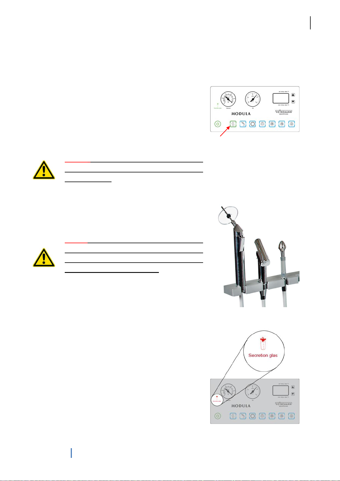
Pressing the button (fig. 4) causes warm air to flow from the
opening. The mirror is warmed at a distance of 3 - 4 cm from this
opening. The mirror heater remains active for about 16 seconds
before switching itself off automatically. In order to avoid a build up
of heat within the casing, the fan continues to run for a further 10
seconds.
Should an excess temperature be detected, a safety thermostat will
deactivate the mirror warmer.
Caution! Do not place any objects or body parts
directly over the opening, as the metal grid can
become very hot.
Fig. 4: Glass display
4.3 Suction with manual emptying (option)
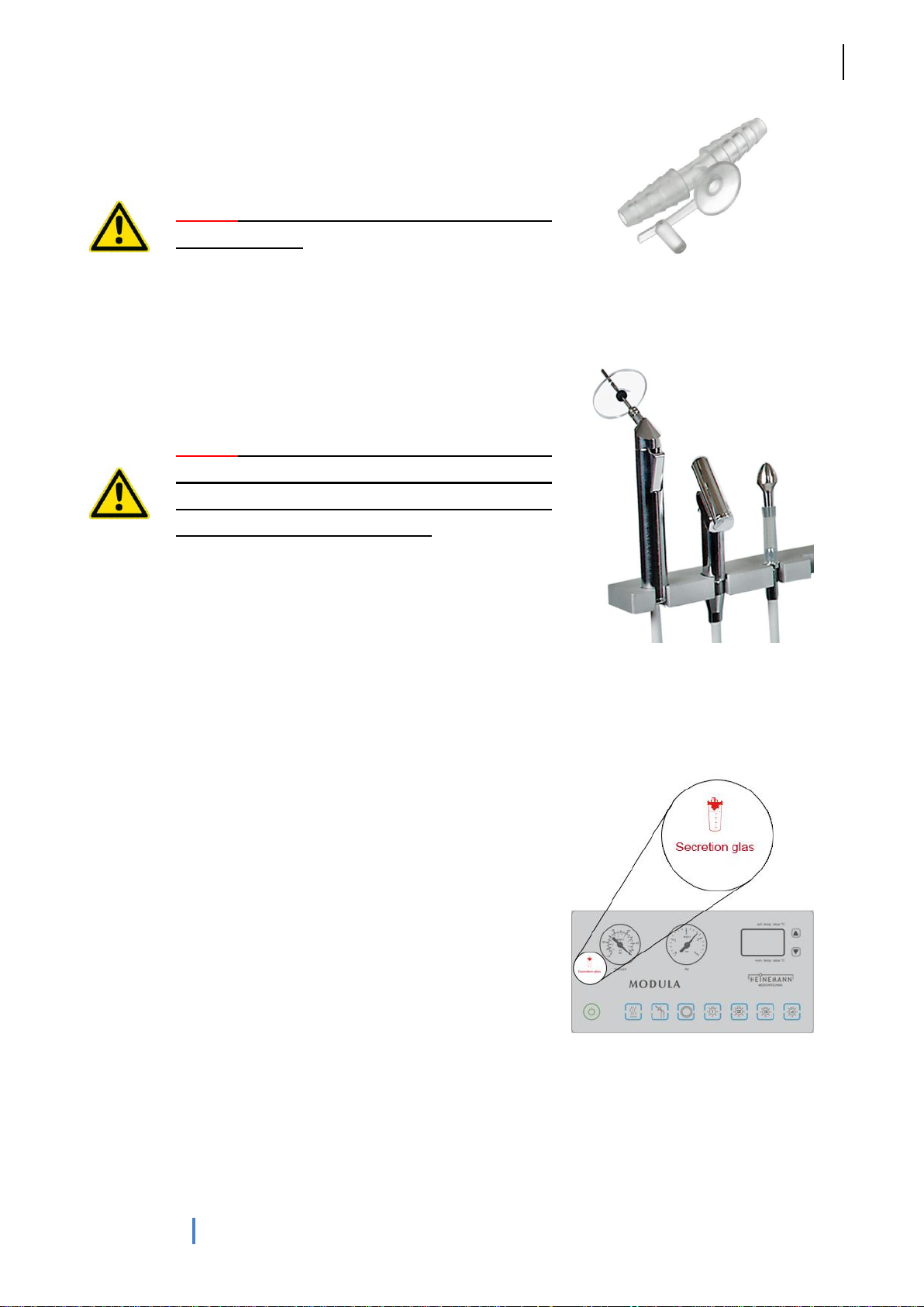
Suction is activated automatically when the suction tube is
removed.
Caution! Please use suitable suction catheters for
suctioning and regulate the volume of flow to
prevent any risk of injury as a result of excessive
pressure focused at a single point.
The end of the suction tube has an adaptor for either an ear rinsing
bowl or a suction cannula (you have to change the suction
cannula after each patient!). After completing treatment, the
vacuum pump deactivates automatically when the suction tube is
replaced in the suction tube holder (the 3rd holder form the left on
the swivel arm). Patient secretions are suctioned into a dedicated
reservoir which is located behind the side hatch, where they are
collected until the reservoir is full.
For reasons of hygiene, this reservoir should be emptied daily. The
reservoir will otherwise continue to fill until the overflow prevention
mechanism is triggered. A red warning light on the control panel
indicates that the reservoir is full. The reservoir must be emptied
when this warning light is illuminated.
Fig. 5: Swivel arm
Fig. 6: Glass display
Page 11
G. Heinemann Medizintechnik GmbH
MODULA Paris
11
User`s manual MODULA Paris (HM_TK_GA-Paris_28062013_06_EN)
Optional manual suction pressure control, allowing the required
suction pressure to be controlled using a control knob or an
adapted “Fingertip” (fig. 7), can be ordered separately.
Caution! The contents of the suction reservoir may
be contaminated.
Fig. 7: Fingertip
4.4 Suction with „Sekretomatik“ system (option)
Suction is activated automatically when the suction tube is
removed.
Caution! Please use suitable suction catheters for
suctioning and regulate the volume of flow to
prevent any risk of injury as a result of excessive
pressure focused at a single point.
The end of the suction tube has an adaptor for either an ear rinsing
bowl or a suction cannula (you have to change the suction
cannula after each patient!). After completing treatment, the
vacuum pump is deactivated automatically when the suction tube is
replaced in the suction tube holder (the 3rd holder form the left on
the swivel arm).
The “Sekretomatik” system is activated automatically when the
suction tube is replaced in its holder. This empties the contents of
the suction reservoir into the drainage system. After emptying, the
suction reservoir is rinsed. A small volume of water is left in the
reservoir to prevent adhesion of secretions.
Optional manual suction pressure control, allowing the required
suction pressure to be controlled using a control knob or an
adapted “Fingertip” (fig. 7), can be ordered separately.
Fig. 8: Swivel arm
Fig. 9: Glass display
Page 12
G. Heinemann Medizintechnik GmbH
MODULA Paris
12
User`s manual MODULA Paris (HM_TK_GA-Paris_28062013_06_EN)
4.5 Cold light sources (option)
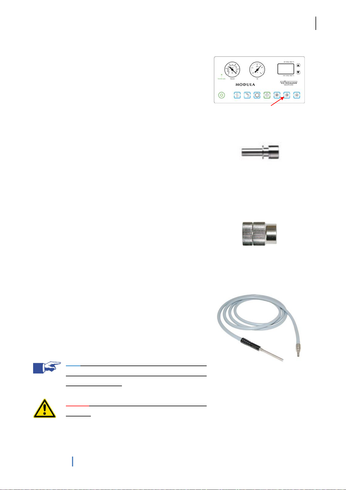
The light sources are activated by cold light source buttons 1 to 4
(fig. 10 buttons 1 to 4). Only one light source can be active at any
one time – an automatic electronic system prevents more than one
light source from being activated simultaneously. The light
extinguishes automatically after 15 minutes.
If you intend to leave the device switched on for a prolonged period
(30 minutes), hold down the light button for 2 seconds when turning
the device on (operation mode). Only one light source can be
activated at any one time. An automatic electronic system prevents
multiple light sources from being activated simultaneously. If a cold
light headlight is used, the cold light source will switch on when the
headlight is removed from its holder. This cold light source can also
be switched on from the control panel as a ‘normal’ cold light
source using the corresponding button, should you subsequently
prefer an alternative use. This requires the headlight holder to
remain actuated or the jack to be removed in order to deactivate
the holder.
All treatment units are equipped with removable STORZ-type light
outputs as standard. Other outputs can be supplied on request. An
adaptor at the end of the optical cable can be used to connect
lenses or endoscopes. Please ensure that you use the correct
adaptor.
Units built after July 2010 can also be equipped with LED cold light
sources. The LEDs are switched on and off using the same
buttons. LED cold light sources have a brightness control next to
the light outputs on the side hatch as standard.
Note! Save energy by only activating the cold light
source when it is really needed. This also extends
the life of the lamps.
Caution! Never direct the light beam directly into
the eyes!
Fig. 10: Buttons „Cold light“
Fig. 11: Storz-adapter (light source
side)
Fig. 12: Storz-adapter (optic side)
Fig. 13: Light cable
Page 13
G. Heinemann Medizintechnik GmbH
MODULA Paris
13
User`s manual MODULA Paris (HM_TK_GA-Paris_28062013_06_EN)
4.6 Compressed air unit (option)
The compressor is activated when the unit is switched on. It
compresses air into a compressed air reservoir until the fixed or
required pressure is achieved. The air pressure (in bar) is displayed
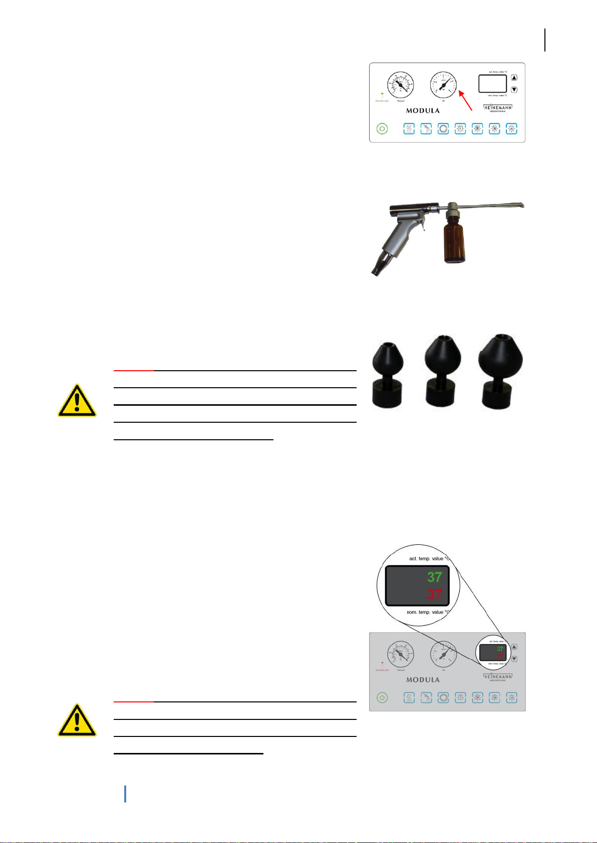
on a right manometer (fig. 14). The delivered pressure can be
adjusted using the lever on the compressed air sprayer. If the lever
is depressed with more force, more air is discharged from the air
outlet. An optional continuously variable control knob allows air
pressure to be adjusted within the range 0.2 to 2,5 bar (required for
“Politzer”-application or for application of children!). The unit is able
to generate a maximum pressure of 2,5 bar.
The medicament sprayers are included with the unit, (optional)
Politzer olive or other devices can be attached to the front end of
the compressed air sprayer (fig. 16).
Caution! Politzerisation may only be performed on
units with an optional compressed air regulator
and at a maximum pressure of 0.5 bar. Please
check the pressure gauge and that the unit is
functioning correctly beforehand.
Fig. 14: Glass display
Fig. 15: Compressed air handpiece
Fig. 16: Politzer olives
4.7 Ear irrigation with water connection (option)
The hot water irrigation system is primarily used for ear irrigation.
The hot water irrigation system is activated by actuating the water
irrigation button. A temperature indicator continuously displays the
set and actual water temperatures. The top temperature is the
actual temperature, the bottom temperature the factory-set target
temperature (37° C).
An electronic safety system prevents the water temperature from
rising and deactivates the water system if the temperature reaches
45° C.
Caution! Check the water temperature before
using the ear irrigation system. Check the
temperature display and run some water over the
back of your hand if necessary.
Fig. 17: Glass display
Page 14
G. Heinemann Medizintechnik GmbH
MODULA Paris
14
User`s manual MODULA Paris (HM_TK_GA-Paris_28062013_06_EN)
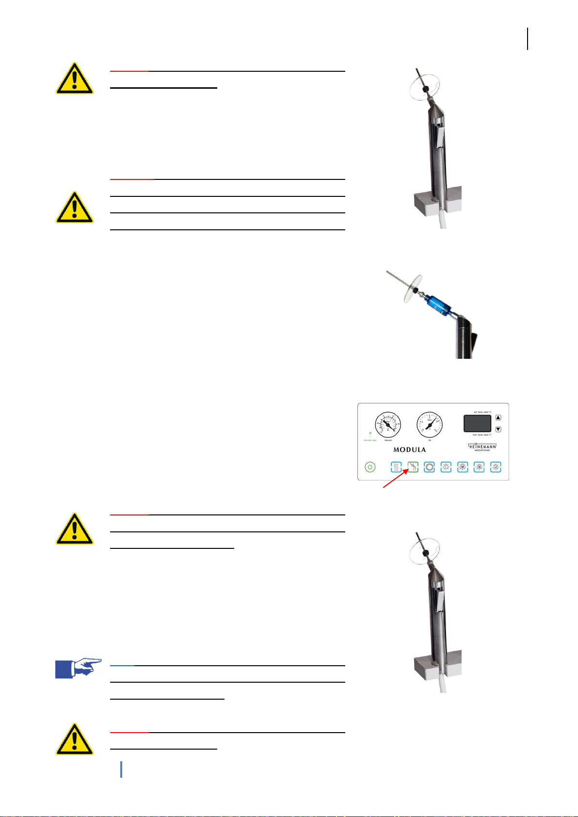
Caution! The water jet must not be directed
directly at the eardrum.
Flow rate (max. 500 ml/min) is adjusted using the lever on the
water handpiece (fig. 18). You have to change the water cannula
after each patient!
Caution! The unit should be taken out of service
and customer services informed if severe
fluctuations in temperature are experienced
(persistent deviations of more than 3°C from 37°C).
The unit can also be equipped with an optional water purification
filter. This single-use filter (4 weeks) is inserted between the water
handpiece and the cannula (fig. 19).
Fig. 18: Water handpiece
Fig. 19: Single-use filter
4.8 Ear irrigation with autonomous water system
(option)
Treatment units equipped with an internal water system are
supplied with water via a 5 liter tank installed behind the unit. The
water is heated by a water heating system.
Caution! Before working with the water irrigation,
ensure that there is enough water in the tank (the
tank should ideally be full).
The hot water irrigation system is activated by actuating the button
(fig. 20). The water heater temperature is factory-set to 37° C. A
thermostat and an additional safety system (activated at 45° C)
provide redundant protection against excess temperatures.
Note! The irrigation system should be deactivated
when not in use. This saves energy and extends
the lifespan of the pump.
Caution! The water jet must not be directed
directly at the eardrum.
Fig. 20: Glass display
Fig. 21: Water handpiece
Page 15

G. Heinemann Medizintechnik GmbH
MODULA Paris
15
User`s manual MODULA Paris (HM_TK_GA-Paris_28062013_06_EN)
Flow rate is adjusted using the lever on the water handpiece, max.
400 ml/min. (fig. 21). You have to change the water cannula
after each patient!
The unit can also be equipped with an optional water purification
filter. This single-use filter (lifespan 4 weeks) is inserted between
the water handpiece and the cannula (fig. 22).
Fig. 22: Single-use filter
4.9 Tube rinsing system (option)
In order to prevent accumulation of secretions and consequent
blockages in the suction system, we recommend using the optional
tube rinsing system.
The tube rinsing system is activated when the suction tube is
pressed onto the tube rinsing nozzle with the silicone tube
(important!) attached. The automatic tube rinsing system starts
after 0.5 s and continues for 3 s. (an error will be registered if the
rinsing nozzle is activated before the suction unit. The ‘Suction
reservoir full’ light on the control panel will flash alternately red and
green. The tube rinsing system will in this case be deactivated).
This can be repeated, but should not be repeated more than three
times, as the collecting reservoir will quickly become full.
Note: We recommend using the tube rinsing
system at least daily.
Fig. 23: Tube rinsing
4.10 Tube rinsing system with disinfectant (option)
In addition to the standard tube rinsing system (using water), it is
also possible to install a disinfectant container for a disinfectant
rinse.
The tube rinsing system is activated when the suction tube is
pressed onto the tube rinse nozzle with the silicone tube
(important!) attached. The automatic tube rinsing system starts
after 0.5 s. The suction tube is rinsed alternately with water and
disinfectant (from the disinfectant container) for 5 s. (an error will be
registered if the rinsing nozzle is activated before the suction unit.
The ‘Suction reservoir full’ light on the control panel will flash
alternately red and green. The tube rinsing system will in this case
Fig. 24: Tube rinsing
Page 16
G. Heinemann Medizintechnik GmbH
MODULA Paris
16
User`s manual MODULA Paris (HM_TK_GA-Paris_28062013_06_EN)
be deactivated). This may be repeated, but should not be repeated
more than three times, as the collecting reservoir will quickly
become full.
Note: We recommend using the tube rinsing
system at least daily.
Recommended disinfectants can be found on page 28 of these
operating instructions.
4.11 Laryngoscope/ endoscope holders (option)
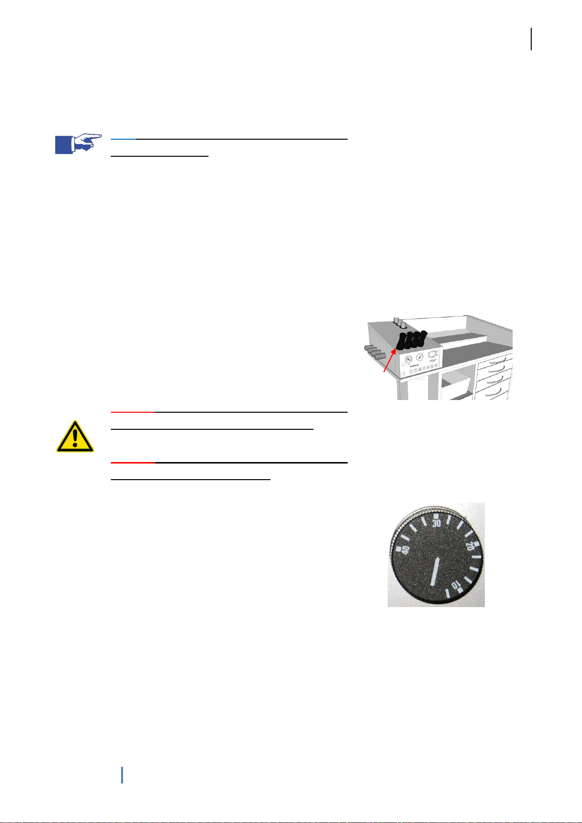
MODULA units offer optional heated endoscope holders (fig. 25) in
which endoscopes can be placed for warming. The holders are
heated to a defined temperature (factory set at 37° C). A thermostat
(fig. 26) allows the holder temperature to be set within a
continuously variable range from 0 to 40° C. The thermostat is
located to the rear of the control panel. Unheated endoscope
holders are also available.
Caution! Only endoscopes which are suitable for
warming should be placed in these holders.
Caution! Before using on patients, please check
the temperature of the endoscope.
Fig. 25: Endoscope holder
4.12 Heated instrument tray (option)
On units with a heated instrument tray, the temperature of the tray
can be controlled via a thermostat. The thermostat is located at the
rear of the unit (fig. 26).
Fig.26: Thermostat
Page 17
G. Heinemann Medizintechnik GmbH
MODULA Paris
17
User`s manual MODULA Paris (HM_TK_GA-Paris_28062013_06_EN)
5 Maintenance and repair
The treatment unit should be serviced annually.
5.1 Cleaning
Caution! Switch off at the main power switch and unplug the unit from the mains before
cleaning or disinfecting. To check that the unit is not under electrical tension, turn it on
at the main power switch.
Caution! Apply cleaning or disinfectant liquids with a soft cloth, do not pour directly onto
the casing. Extra care is required when using flammable liquids. Do not allow any liquid
to run into the device.
Clean the surface of the MODULA Paris using a soft cloth soaked in a non-aggressive cleaning agent or
disinfectant. Do not use ammonia-containing (e.g. Sidolin) or abrasive cleaning agents, as they will destroy
the painted surface over time. All-purpose cleaners and ethanol are particularly suitable as cleaning agents.
Components should always be subjected to a visual inspection after cleaning, with particular attention paid to
cracks, breaks and mechanical failure. Do not use alcohol-containing cleaning agents when cleaning the
perspex cover.
Note! Please clean the suction tubing at least daily using the optional integrated tube
rinsing system (option).
If your unit is not equipped with an integrated tube rinsing system, take a container containing a non-foaming
disinfectant solution and clean and disinfect the suction system by suctioning this solution up.
The suction reservoir (for manual suctioning) should be cleaned whenever the device is serviced (six
monthly). To do so, open the left side hatch, remove the suction reservoir and clean thoroughly. The
reservoir is resistant to disinfectants.
Never operate the treatment unit without the suction reservoir.
Note! Remember that normal cleaning of treatment surfaces achieves a 50 to 80%
reduction in the number of microorganisms. Effective disinfection achieves a statistically
significant reduction of at least 84 to 99.9%. (Source: RKI)
When using disinfectants, always follow the manufacturer’s instructions with regard to concentration and how
long to leave the disinfectant to take effect.
Page 18
G. Heinemann Medizintechnik GmbH
MODULA Paris
18
User`s manual MODULA Paris (HM_TK_GA-Paris_28062013_06_EN)
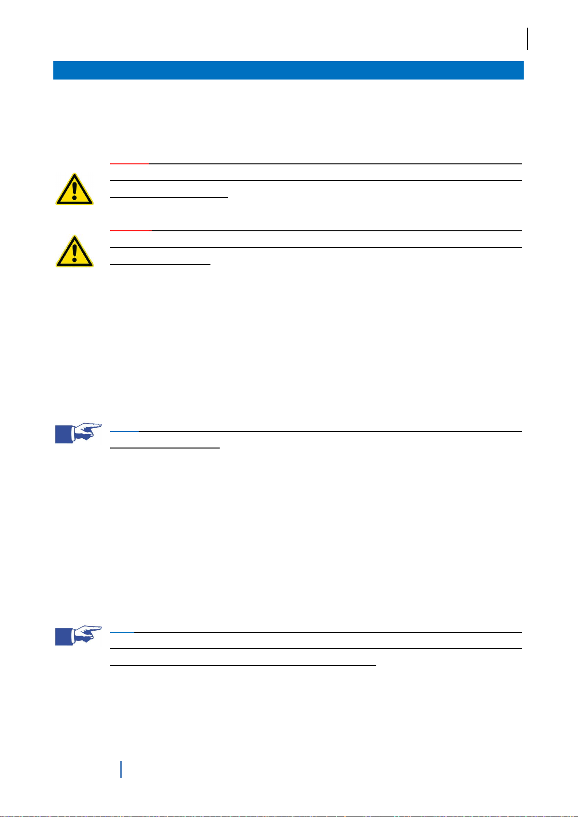
Caution! Following disinfection, the components of the nebuliser, water jet and silicone
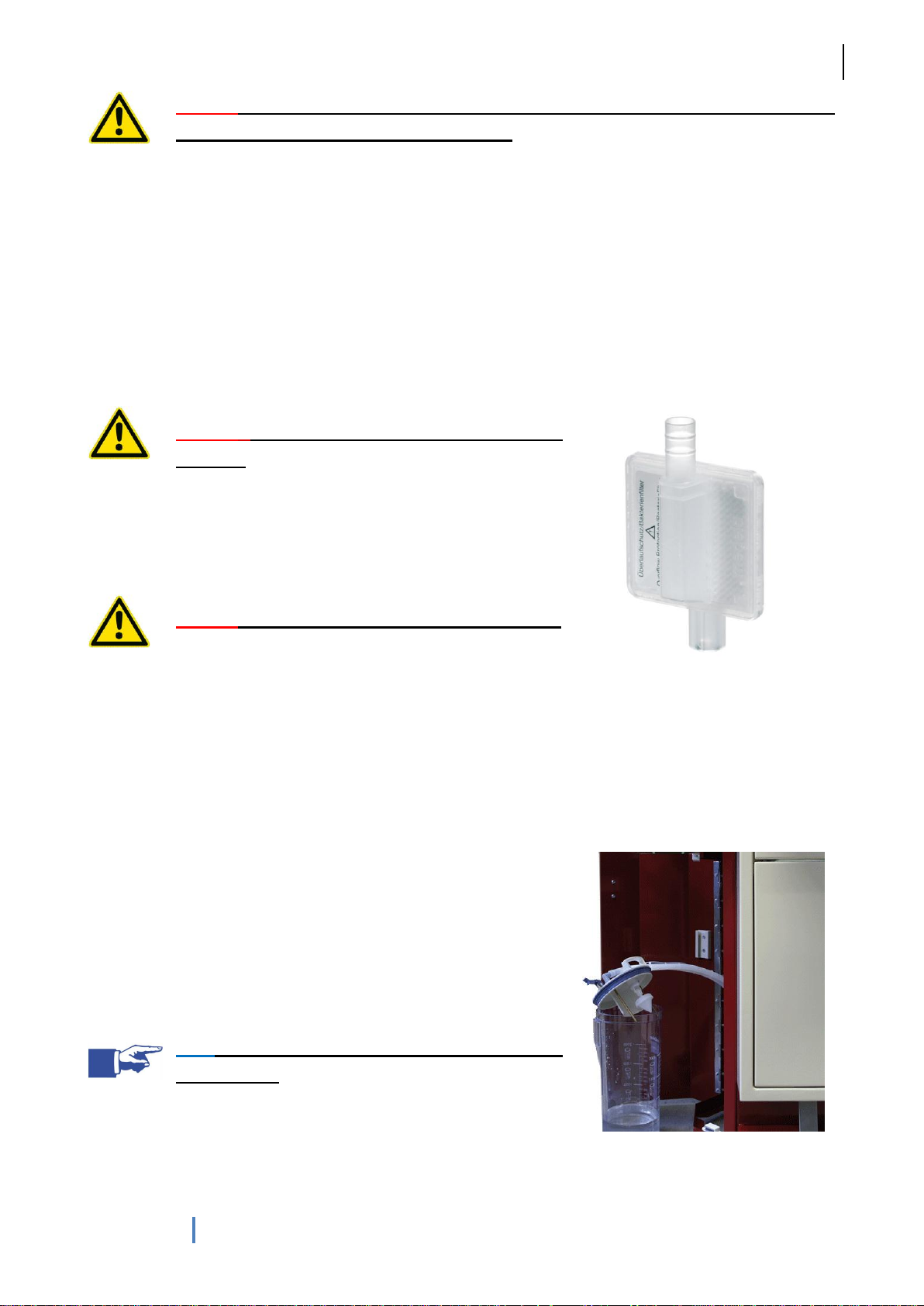
For hygiene reasons, the suction system outlet is fitted with a
bacteria filter. This is located at the rear of the left side of the unit.
Caution! Please dispose of contaminated waste
correctly.
To change the filter, disconnect the two silicone hoses from the filter
and then connect the hoses with the new filter. The flow direction is
not important.
Caution! Use gloves, the filter may be contaminated.
It is recommended to change the filter once a year or as needed.
Fig. 27: Antibacterial filter/ overflow
protection
If your MODULA Paris has a manual suction reservoir, it must be
emptied at least once a day at the end of the day, and more
frequently if it becomes full (indicated by a warning lamp).
To empty the reservoir, open the left side hatch, remove the lid and
tube, remove the suction reservoir and clean thoroughly (fig. 28).
Note! The reservoir is resistant to disinfectants (not
autoclavable).
Fig.28: Left side cover with suction
reservoir
tubing should be rinsed until free of residues.
As with other instruments, all auxiliary devices and associated instruments (e.g. ear irrigation cannulae,
instrument trays, dishes for discarded instruments, etc.) should be regularly sterilised or disinfected. This
includes water jet cannulae, the nebuliser drug vial nebulisers and the silicone suction tubing.
5.2 Changing the bacteria filter
5.3 Emptying the suction reservoir
Page 19
G. Heinemann Medizintechnik GmbH
MODULA Paris
19
User`s manual MODULA Paris (HM_TK_GA-Paris_28062013_06_EN)
5.4 Replacing the waste bag
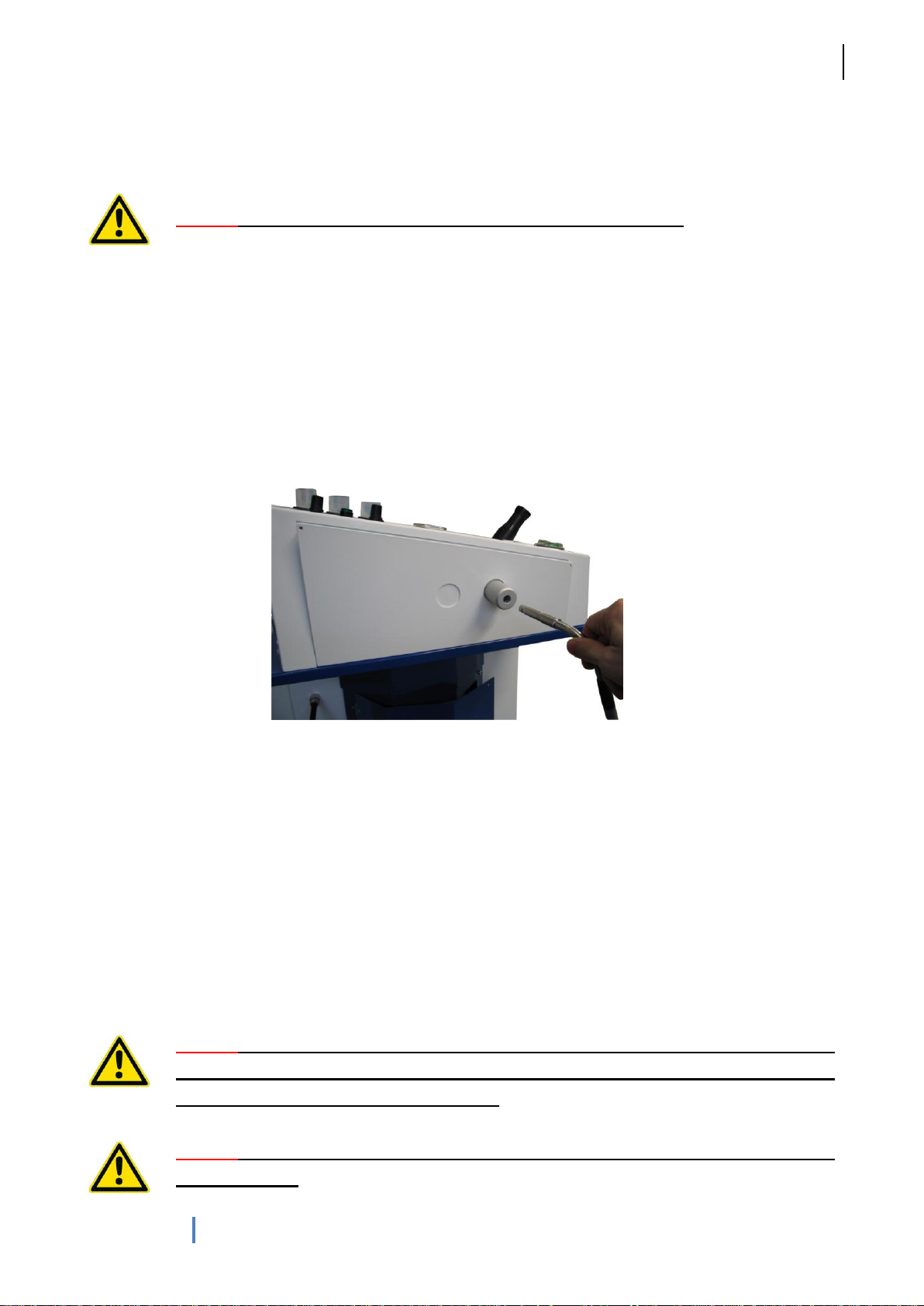
Fig. 29: Outputs for cold light sources
For hygiene reasons, check the waste bag at the end of every day and dispose of it if it is even part full.
Caution! Pay attention to the proper disposal of contaminated waste!
5.5 Optical cable
If your unit has one or more cold light sources, a range of lenses can be attached to the cold light adaptor via
an optical cable. The light adaptors have a STORZ connector. Optional detachable light outputs for
connecting Storz, Wolf, Olympus and Pentax connectors are available. The optical cable is simply inserted or
removed. No additional tools are required.
There is a pre-set locking screw beneath the cable connector. This can also be used to adjust the force with
which the locking screw secures the cable. To fix the optical cable more tightly in the connector, carefully
tighten the screw and check the force required. To fix the optical cable less tightly, carefully loosen the
screw.
A range of optional optical cable adaptors (Wolf, Storz, Olympus, etc.) can be ordered separately.
5.6 Replacing the halogen lamp
Caution! Always switch off at the main power switch before replacing the halogen lamp.
Unplug the treatment unit at the mains. To check that the unit is not under electrical
tension, turn it on at the main power switch.
Caution! Allow the halogen lamp to cool for at least 15 minutes before replacing, as it
may be very hot.
Page 20
G. Heinemann Medizintechnik GmbH
MODULA Paris
20
User`s manual MODULA Paris (HM_TK_GA-Paris_28062013_06_EN)
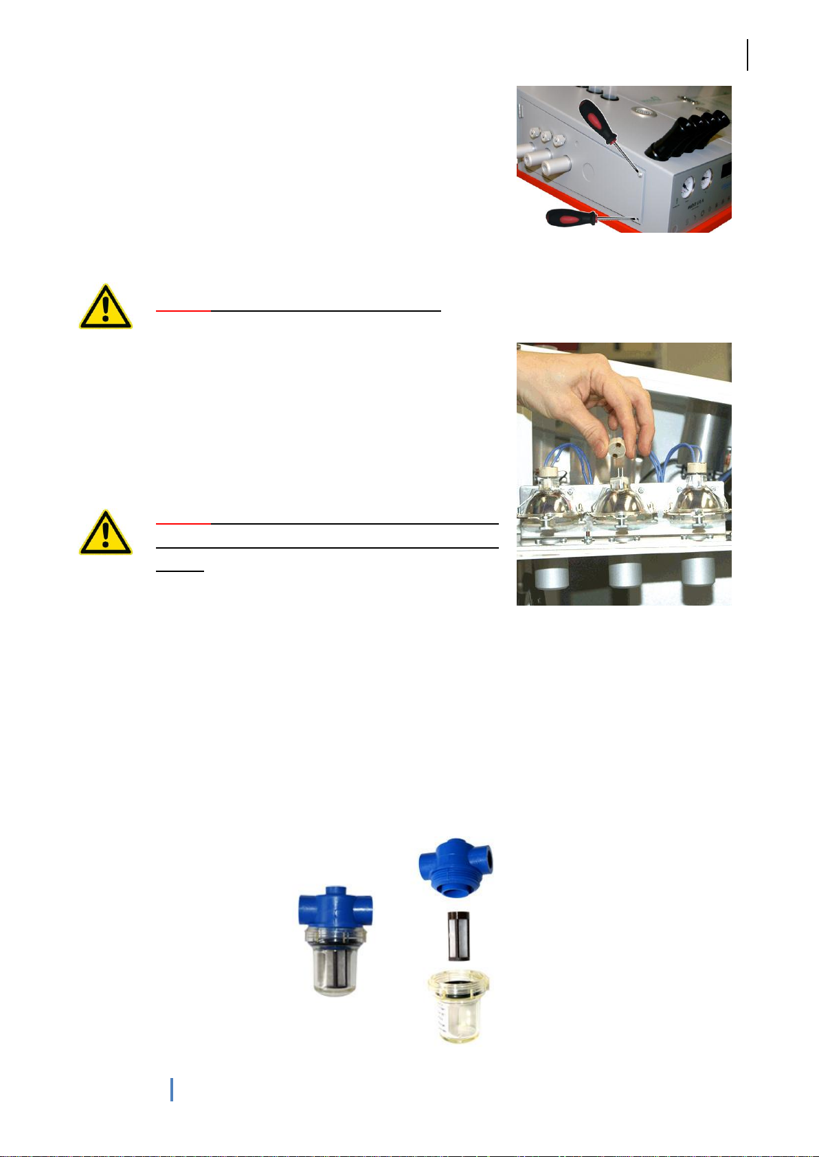
To replace the halogen lamp you will require a screwdriver able to
unscrew both screws (fig. 30). Open the side cover.
The device must be permitted to cool down before replacing
defective halogen lamps, as the lamps may be very hot. Use only
lamps which conform to the device specifications.
Fig. 30: Left side cover
To remove a halogen lamp, pull off the cable (fig. 31) and then pull
forward out of the bulb fitting. To insert a new halogen lamp, perform
this process in reverse (replacements are included with the device).
After replacing the halogen lamp, replace the console lid and tighten
the two screws.
Caution! The console lid must be replaced before
the treatment unit is reconnected to the main power
supply.
Fig. 31: Bulb fittings
Fig. 32: Water filter
Caution! Use only 15 V/10 A halogen lamps.
The following tasks may only be performed by qualified personnel.
5.7 Cleaning the water filter
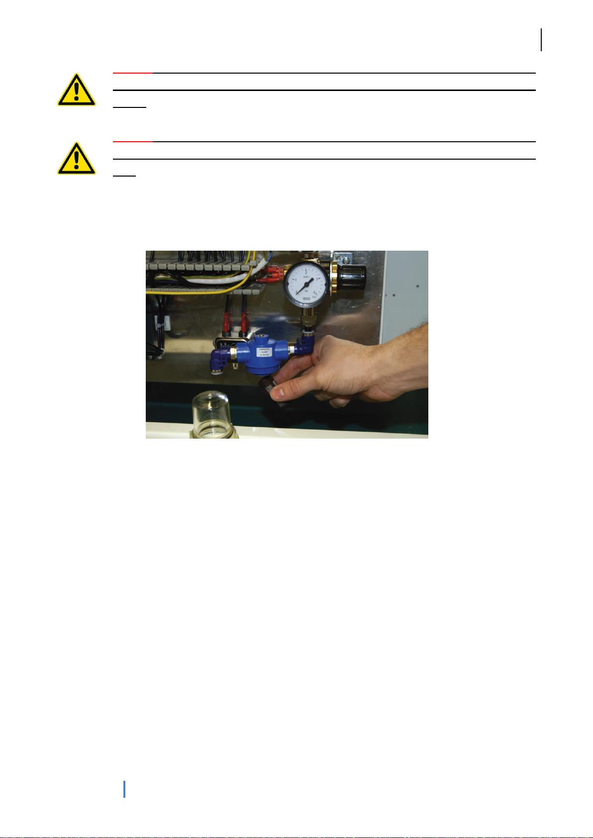
To prevent blockages or problems in the water system, the waste water filter (fig. 32) should be checked and
cleaned as necessary each time the device is serviced.
Page 21
G. Heinemann Medizintechnik GmbH
MODULA Paris
21
User`s manual MODULA Paris (HM_TK_GA-Paris_28062013_06_EN)
Caution! Switch off the treatment unit at the main power switch and unplug from the
Fig. 33: Water filter with water manometer
mains. To check that the unit is not under electrical tension, turn it on at the main power
switch.
Caution! If your MODULA unit has an internal water supply and you are carrying out work
on the interior of your unit, you must wait 30 minutes to allow the water heater unit to
cool.
The procedure for cleaning the filter is as follows: Unscrew the retaining screws on the rear of the unit using
a screwdriver.
1. Turn off the water feed.
2. On MODULA units with a water tank, disconnect the tube from the tank.
3. On MODULA units with a continuous flow heating unit, close the mains water valve and briefly
operate the water jet.
4. Water pressure is shown on the manometer next to the water filter. The needle will drop to zero (fig.
33).
5. Keep a couple of cloths to hand to catch any remaining water in the filter and carefully rotate the
transparent plastic cover anti-clockwise.
6. Remove the filter cartridge and rinse with tap water until free of dirt particles. If severely
contaminated, replace the filter element.
7. Reassemble by following the reverse procedure.
Page 22
G. Heinemann Medizintechnik GmbH
MODULA Paris
22
User`s manual MODULA Paris (HM_TK_GA-Paris_28062013_06_EN)
5.8 Replacing fuses
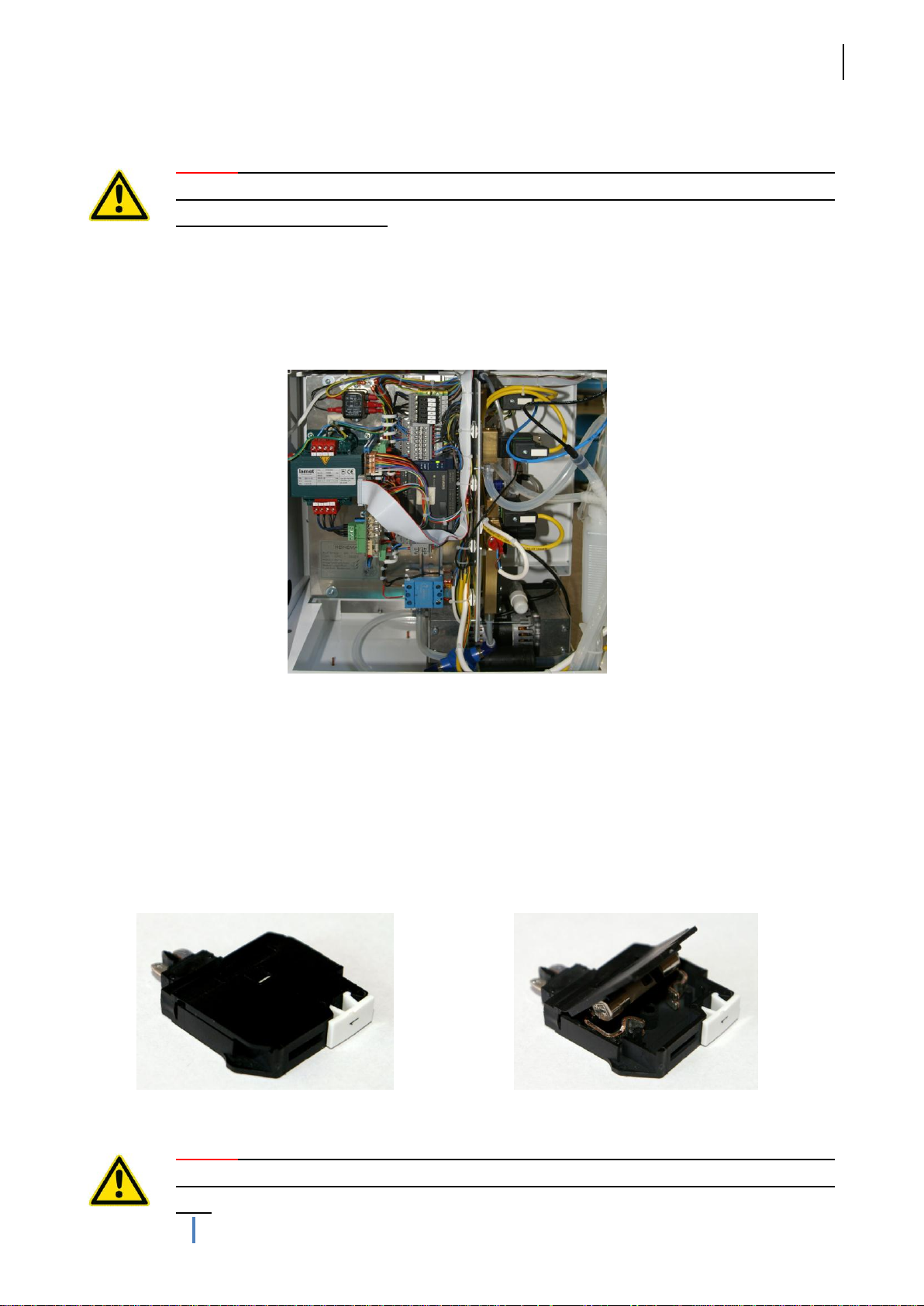
Fig. 34: Back of MODULA Paris
Fig. 35: Fuse closed
Fig. 36: Fuse open
Caution! Always switch off at the main power switch before replacing fuses. Unplug the
treatment unit at the mains. To check that the unit is not under electrical tension, turn it
on at the main power switch.
After unscrewing the retaining screws, the rear hatch can be easily removed to reveal the fuse holder
containing the fuses. A complete electrical circuit diagram, including fuse diagram, is printed on the inside of
the cover.
The blown fuse should be located using the circuit diagram and replaced with an identical fuse (same fuse
rating). Replacement fuses are supplied with the unit.
The fuse holder must be pulled out of its fitting. The holder can then be easily opened using a flat-head
screwdriver. The mini fuse can now be replaced easily (fig. 35, 36). To avoid confusion, remove only one
fuse at a time.
Caution! If your MODULA unit has an internal water supply and you are carrying out work
on the interior of your unit, you must wait 30 minutes to allow the water heater unit to
cool.
Page 23

G. Heinemann Medizintechnik GmbH
MODULA Paris
23
User`s manual MODULA Paris (HM_TK_GA-Paris_28062013_06_EN)
6 Hygiene
Bear in mind that the tap water used by the unit for warm water irrigation is low in micro-organisms, but is not
sterile. (36 - 42% of nosocomial Pseudomonas aeruginosa infections are traceable to tap water primarily
contaminated at the tap (Source: RKI, Gesundheitsschutz 4/2004). To protect yourself and patients, we
therefore recommend incorporating a downstream sterile filter.
We also offer an optional water purification filter (lifespan 4 weeks) for insertion between the water
handpiece and cannula.
The following basic principles should be observed when working with the ENT treatment unit:
wipe the unit at least daily with a suitable cleaning agent (for recommended cleaning agents, see
page …)
after each patient, replace all instruments, handpieces, instrument trays, etc. used with disinfected or
sterile items (for recommended cleaning agents, see page …)
on units with a water tank, always use fresh, cold tap water only and check the water level in the tank
clean the tube rinsing system with a non-foaming disinfectant daily (for recommended disinfectants,
see page …)
empty the waste receptacle daily
empty the suction reservoir
Note! Over-dilute or ineffective disinfectant solutions can become sources of infection,
particularly with gram-negative bacterial (especially enterobacteriaceae, pseudomonads),
especially when prepared in contaminated containers and stored for long periods.
Exact dosing of disinfectants is required for effective disinfection and to prevent selection of micro-organisms
and development of disinfectant resistance. (Source: RKI)
Page 24

G. Heinemann Medizintechnik GmbH
MODULA Paris
24
User`s manual MODULA Paris (HM_TK_GA-Paris_28062013_06_EN)
7 Guarantee
We offer a guarantee for all parts of the MODULA treatment unit for 12 months from the date of installation.
Longer guarantee periods may be agreed in your purchase agreement.
The guarantee includes the fastest possible repair by our service department in the even of a fault. For your
own benefit, you should therefore contact us immediately (contact).
The following points are not covered by our guarantee:
incorrect usage of the MODULA, accessories or special equipment
access by or operation by unauthorised persons (e.g. electricians, water engineers)
force majeure (e.g. fire, water ingress, lightning strike, etc.)
The manufacturer holds itself responsible for effects on the safety and reliability of the treatment unit only if:
extensions, reinstallation, modification or repairs have been performed exclusively by persons
authorised by the manufacturer
the room electrical and water systems meet the requirements of IEC-60601
the treatment unit is used in accordance with these operating instructions
Caution! Repairs to the MODULA treatment unit may only be carried out by G.
Heinemann Medizintechnik GmbH or agents expressly authorised to carry out such work.
Page 25
G. Heinemann Medizintechnik GmbH
MODULA Paris
25
User`s manual MODULA Paris (HM_TK_GA-Paris_28062013_06_EN)
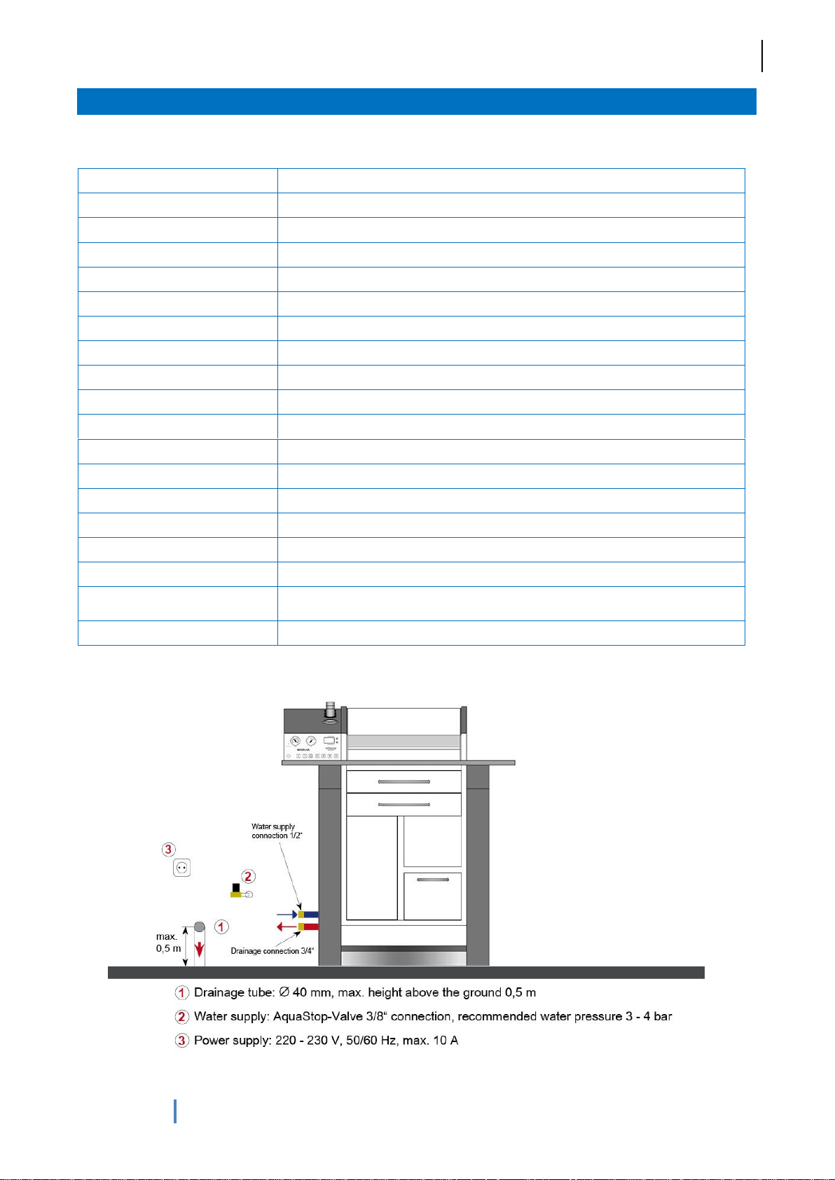
8 Annex
Power supply:
230 V (+/- 10%)
Frequency:
50/60 Hz
Current consumption:
max. 10 A
Power consumption:
max. 2,3 kVA
Classification:
IIa
CE-Sign:
MEDCERT Kenn-Nr. 0482
Protection class:
I
Degree of protection:
Type: B
Air-pressure (option):
Compressor oilfree, 12 L/min by 2700 U/min and 138 VA, adjustable from 0,2 to 4,0 bar
Vacuum pump (option):
Vacuum pump oilfree, 40 L / min up to -0,85 bar und 150 VA (option: 60 L/min)
Water heater (option):
max. 1500 VA (long-term use), minimum water pressure 1,5 bar
Water temperature: (option):
37°C +/- 1°C
Watertank (option):
5 liter
Light source, halogen (option):
150 VA, 15 V
Light source, LED (option):
30 VA, 12 V
Weight:
140 kg
Dimensions (W x H x D):
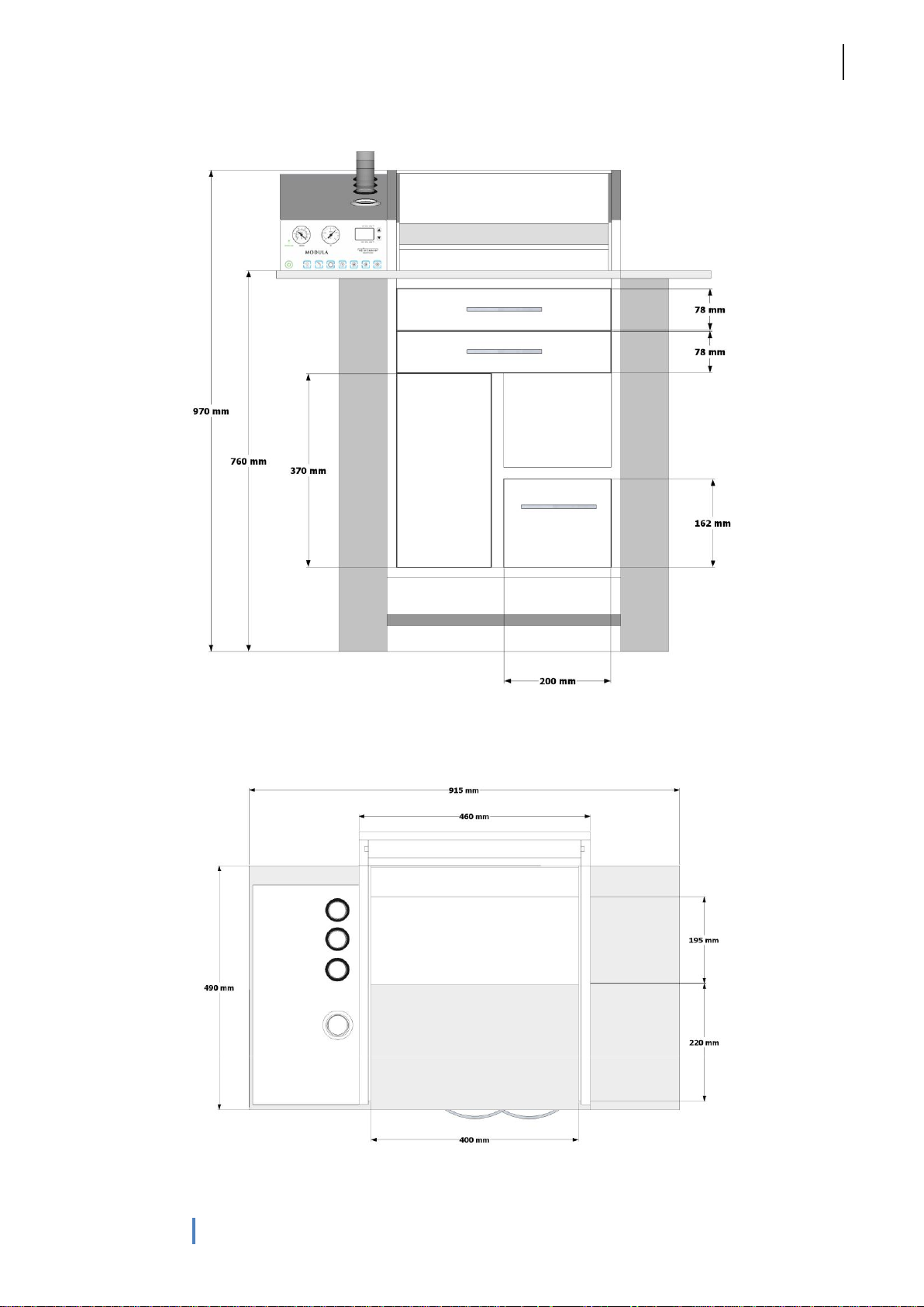
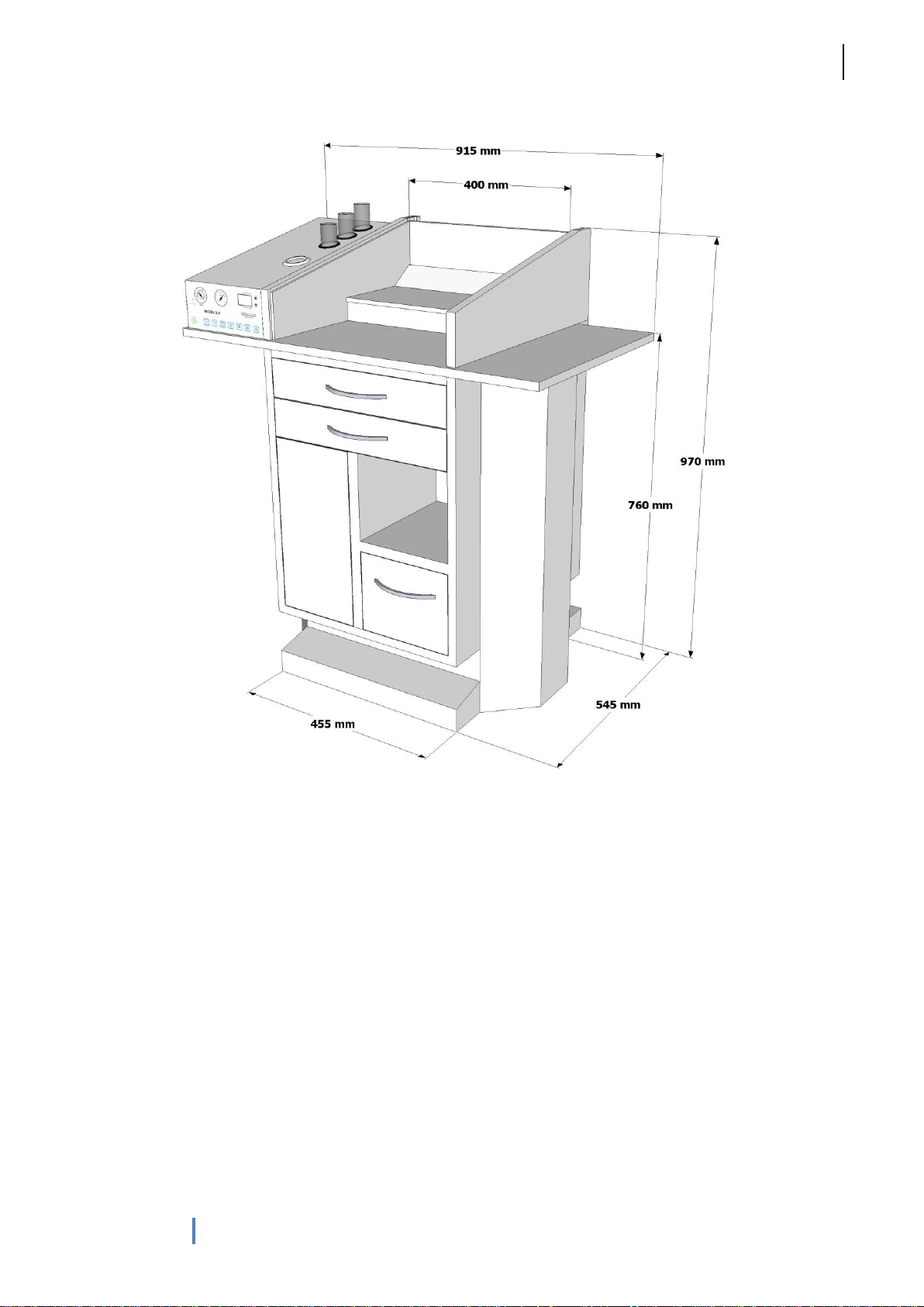
915 x 970 x 545 mm
Connections:
Power cabel and AquaStop-Valve: 2 m
Water supply and drainage hoses: 2 m
Ambient conditions:
Temperature: +5° to +35°C, Humidity: 30 to 65%
Fig. 37: Connection plan
8.1 Technical details
8.2 Figures
Page 26
G. Heinemann Medizintechnik GmbH
MODULA Paris
26
User`s manual MODULA Paris (HM_TK_GA-Paris_28062013_06_EN)
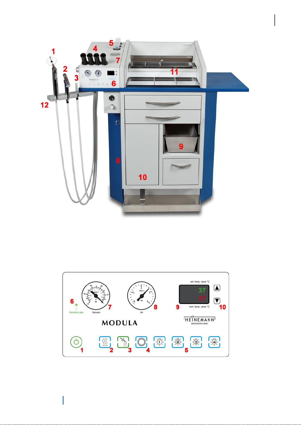
Fig. 38: MODULA Paris, front view
Fig. 39: Glass display
1: Water handpiece, 2: Compressed air handpiece, 3: Suction handpiece, 4: Endoscope holder, 5: Quiver for
disinfection, 6: Glas control panel, 7: Mirror heater, 8: Left side cover, 9: Tray for used instruments, 10:
Waste bin, 11: Instrument level with built-in illumination, 12: Swivel holder
1: Stand-By-button, 2: Button „Mirror heater“, 3: Button „Ear rinsing“, 4: Button „Option“, 5: Button „Cold light
sources“, 6: Suction reservoir indicator, 7: Manometer „Vacuum“, 8: Manometer „Compressed air“, 9:
Temperature display for ear rinsing system, 10: Buttons for “Vestitherm”-Option
Page 27
G. Heinemann Medizintechnik GmbH
MODULA Paris
27
User`s manual MODULA Paris (HM_TK_GA-Paris_28062013_06_EN)
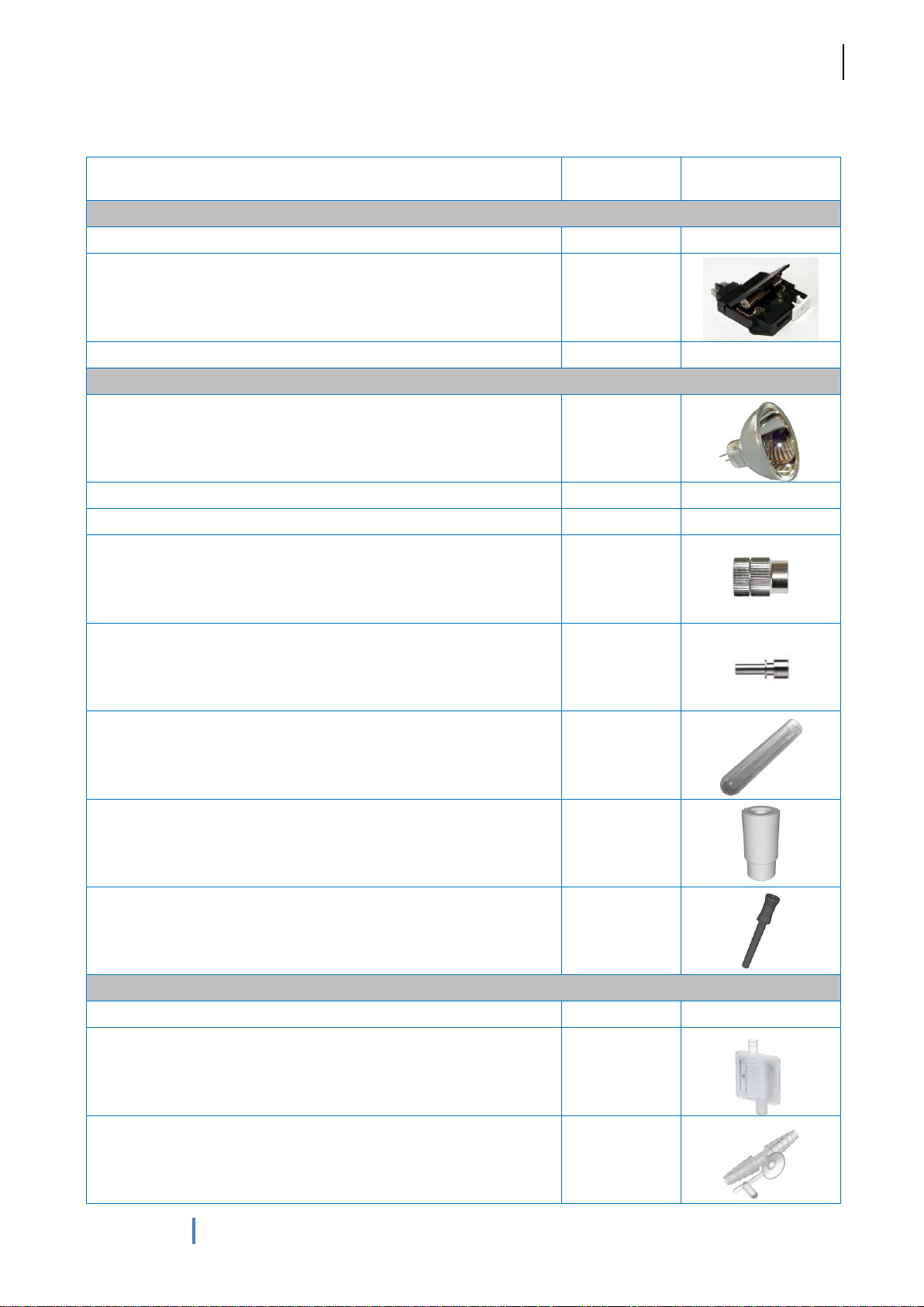
8.3 Consumables & spare parts
Product description
REF
Figure
Electrical system
Fuses set
STA20-00015
Fuse holder
MOD34-00104
Relais set
MOD14-04007
Light system
Replacement lamp 150 W (halogen)
MOD10-02701
Cold light cable, 90°, l = 180 cm
0150-30000
Cold light cable, 0°, l = 180 cm
0150-30100
Light cable adapter, endoscope side (Storz, Wolf...), 1 pc
0150-31000
Light cable adapter, light source side (Storz, Wolf...), 1 pc
0150-32000
Disinfection quiver for rigid endoscopes, autoclaveable
0150-50230
Adapter disinfection quiver, material: silicone (for rigid endoscopes)
0150-50220
Endoscope quiver
MOD13-06104
Suction system
Silicon tubes for suction hose (10 pcs.)
MOD21-08619
Overflow-/ bacterial filter (for units after 2011), 1 Stück
210-0770572
Fingertips for the temporary reduction of the suction performance
(100 pcs.)
0120-50100
Page 28
G. Heinemann Medizintechnik GmbH
MODULA Paris
28
User`s manual MODULA Paris (HM_TK_GA-Paris_28062013_06_EN)
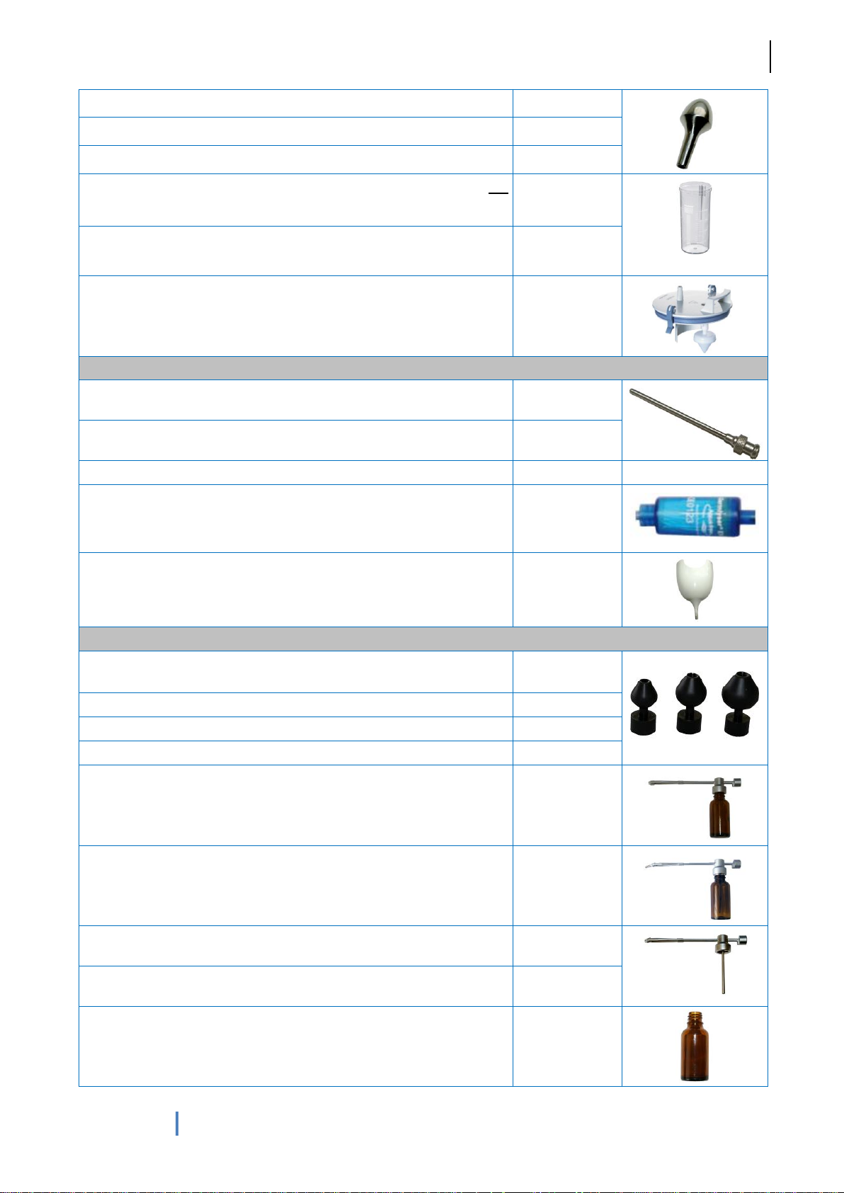
Nose olives (metal), adapted on the suction hose, small
0120-50210
Nose olives (metal), adapted on the suction hose, medium
0120-50220
Nose olives (metal), adapted on the suction hose, large
0120-50230
Secretion glass for manual emptying, 2 L (material: PC, not
autoclavable)
MOD18-05809
Secretion glass for manual emptying, 2 L (material: PSU,
autoclavable)
MOD18-05820
Cover for secretion glass (manual emptying) with overflow sensor
MOD18-05810
Water system
Cannula for water handpiece (Luer-Lock), 80 mm
0130-50025
Cannula for water handpiece (Luer-Lock), 110 mm
0130-50026
Protection cover for the water hanpiece
0130-50030
Water decontamination system with cartridge to be connected on
the water handpiece (to be replaced each month)
0130-42000
Ear rinsing bowl – adaptable to suction hose
0130-50000
Air pressure system
Politzer olives (plastic) for adaption to the handpiece for
compressed air - set with 3 different sizes
0140-21300
Politzer olives (plastic), small
0140-21301
Politzer olives (plastic), medium
0140-21302
Politzer olives (plastic), large
0140-21303
Spray bottle for fluids, complete (glass and sprayer)
0140-60101
Spray bottle for powder, complete (glass and sprayer)
0140-60102
Sprayer for fluids
0140-60103
Sprayer for powder
0140-60105
Spray bottle glass
0140-60104
Page 29
G. Heinemann Medizintechnik GmbH
MODULA Paris
29
User`s manual MODULA Paris (HM_TK_GA-Paris_28062013_06_EN)
Fig. 40: MODULA Paris, front
Fig. 41: MODULA Paris, top
Page 30
G. Heinemann Medizintechnik GmbH
MODULA Paris
30
User`s manual MODULA Paris (HM_TK_GA-Paris_28062013_06_EN)
Fig. 42: MODULA Paris, perspective
Page 31

G. Heinemann Medizintechnik GmbH
MODULA Paris
31
User`s manual MODULA Paris (HM_TK_GA-Paris_28062013_06_EN)
Page 32

G. Heinemann Medizintechnik GmbH
MODULA Paris
32
User`s manual MODULA Paris (HM_TK_GA-Paris_28062013_06_EN)
Manufacturer:
G. Heinemann Medizintechnik GmbH
Leibnizstraße 13-15
D-24568 Kaltenkirchen
GERMANY
Phone: +49 4191-95379-0
Fax: +49 4191-9537937
E-mail: [email protected]
Web: www.heinemann-ent.de
 Loading...