

Page 1
Heiland electronic GmbH
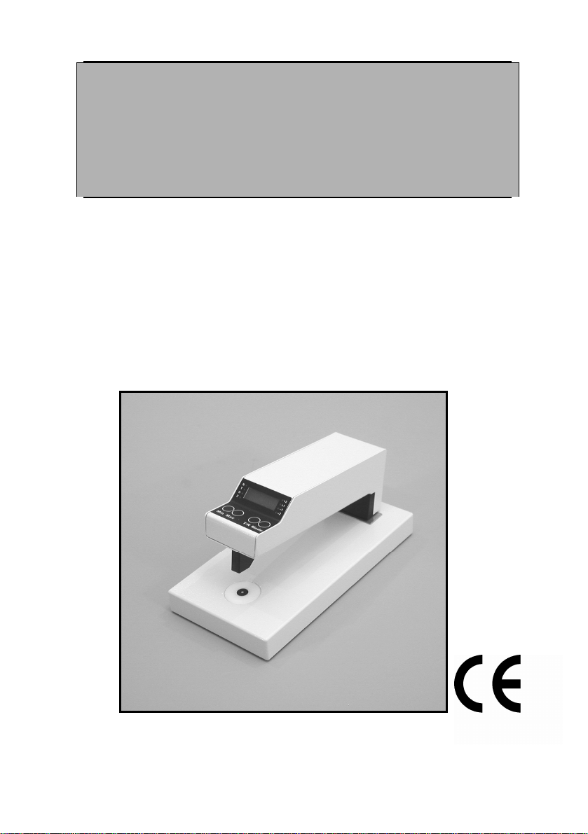
TRD 2
B&W-Densitometer
User manual
Version 6.2
Page 2

Table of Contents
1. GENERAL INFORMATION.....................................................................3
2. SAFETY REGULATIONS.......................................................................3
3. AREA OF APPLICATIONS.....................................................................3
4. INSTRUMENT DESCRIPTION
4.1. STANDARDVERSION (FIGURE 1)......................................................4
4.2. OPTIONS (FIGURE 2,3)......................................................................6
5. INSTALLATION
5.1. LOCATION CONDITIONS...................................................................8
5.2. SWITCHING ON..................................................................................9
6. READING
6.1. INSTRUCTIONS TO AVOID INCORRECT READING..........................9
6.3. INSTRUCTIONS FOR RESET TO ZERO...........................................10
6.4. DENSITY MEASUREMENT...............................................................11
7. CARE OF INSTRUMENT......................................................................12
8. CALIBRATION CHECK........................................................................12
9. GUARANTEE.......................................................................................13
10. TECHNICAL DATA.............................................................................14
2
Page 3

1. General information
Dear Customer,
thank you for purchasing a Heiland densitometer. In order to become
familiar with the operation of your instrument, please read these
instructions carefully and completely before your first use.
The packaging of the instrument is shock-absorbent and should be
kept for the case of shipping and repairs.
Use only the original packaging for transportation and shipment. First
lay the cardboard on the surface of the base unit, then place the roll
of bubble film between measuring head and base unit. Finally put the
instrument inside the plastic bag and then into the shipment-box.
Don't forget the calibration strips!
CAUTION:
Never use the removable measuring head (Opt. 01) for carrying
the instrument. The base unit may separate and drop off!
Damages caused by this are not included by guarantee.
2. Safety regulations
§ Assure that the main voltage and the frequency on the power
supply unit is the same as the one indicated on the identification
label of the power supply unit
§ It is not permitted to exchange the power supply against another
one without the permission of the manufacturer.
§ Always keep the instrument and the power supply in a dry place
and never immerse it in any kind of liquid.
§ To prevent electric shock do not open, neither the densitometer
nor the power supply. There are no user serviceable parts inside.
3. Area of applications
The densitometer is designed for the measurement of density values
of B&W and other nearly grey coloured subjects. The reading is
possible in units of logarithmic density. Please contact the
manufacturer, if you like to use the instrument for other applications.
The modular construction of the instrument enables the user to
optimise it according to his requirements.
TRD 2 USER MANUAL Version 6.2 3
Page 4
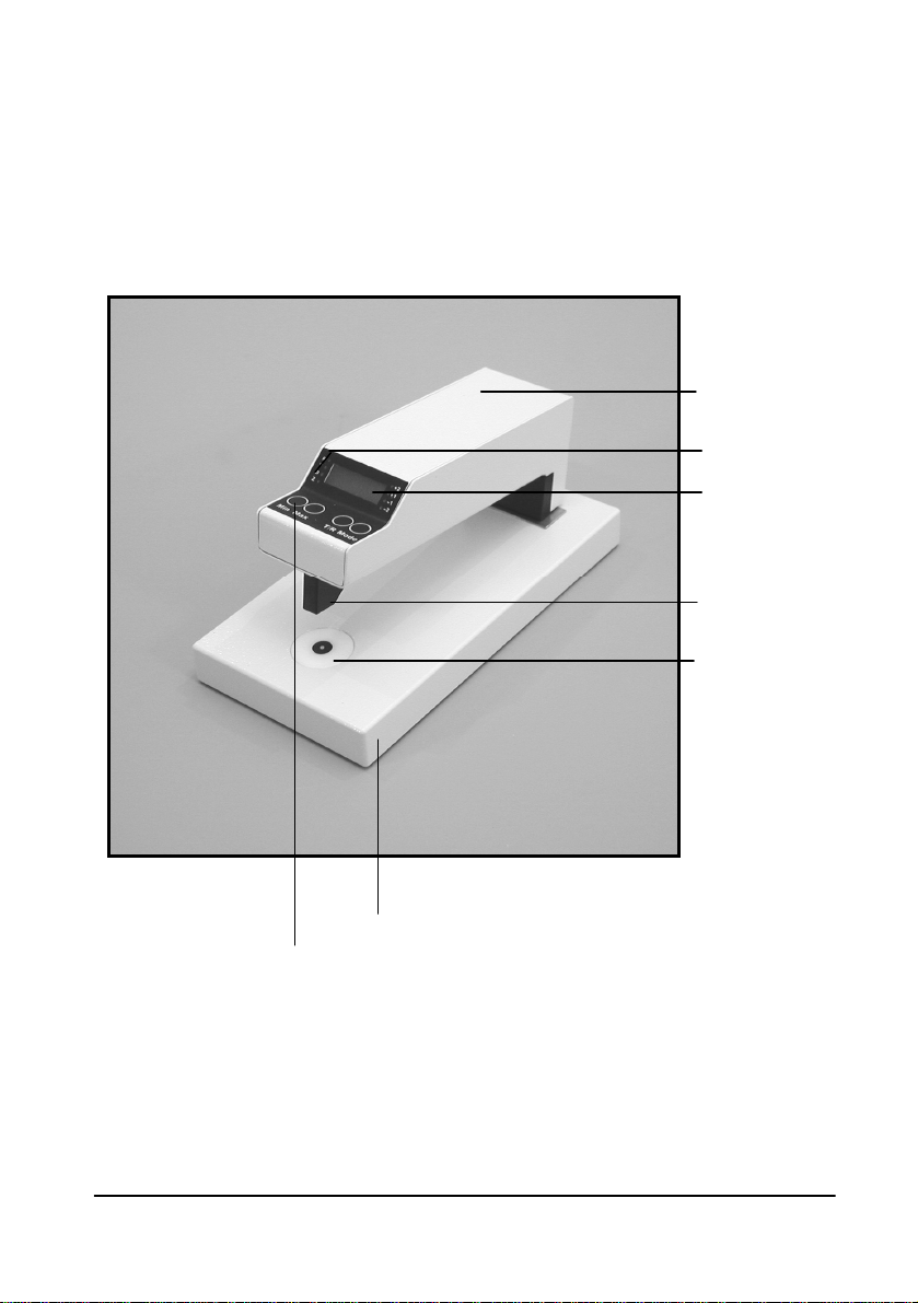
4. Instrument description.
Figure 1, TRD 2 standard version
Measuring
head
Mode-LED‘s
Display
Probe
Aperture
4
Base unit
Mode and
reference
buttons
Page 5

4.1 Standard version
§ The id-label is located on the bottom of the base unit.
§ The base unit contains the transmission lamp. The light is emitted
through an opal aperture.
§ The top of the base unit serves as a platform, on which the film or
photo rests during measurement.
§ The measuring arm is mounted to the base unit by a precise
bearing. The integrated spring pushes the measuring head in the
upper position. The head contains the sensing electronic, below
of it the probe and the reflective lamp are mounted.
§ One of the lamps and the displays are automatically activated
when the measuring head is lowered.
§ The 3-digit display allows a precise reading down to 0.01 log.D.
If the minimum sensitivity of the system is reached or if the
measuring head is depressed too fast, the display will flash
"-888". If reading a lower density than at reset, a negative sign will
appear. If the display flashes E XX (where XX is the number of
the error) please consult the manufacturer.
§ The LED's beside the 3-digit display show the selected
measurement mode while the measuring arm is lowered.
T: Transmission measurement
R: Remission measurement
D: Density values are displayed
§ The switches on the top of the measuring arm are only active,
when the display is on.
The Min switch sets the display to zero, with
T/R you switch between remission and transmission mode.
TRD 2 USER MANUAL Version 6.2 5
Page 6
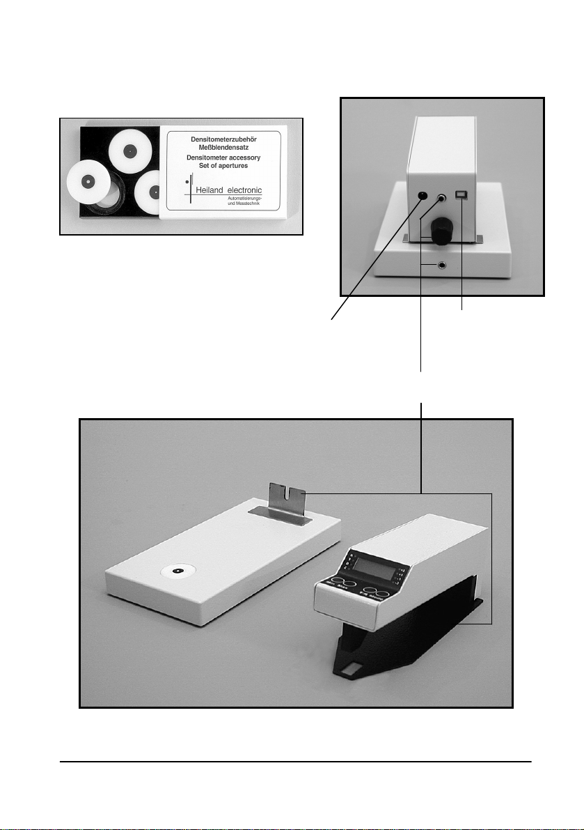
Figure 2, Rear side and options
Opt.02
Power Supply
Opt.03
Opt.01
6
Page 7
4.2 Options
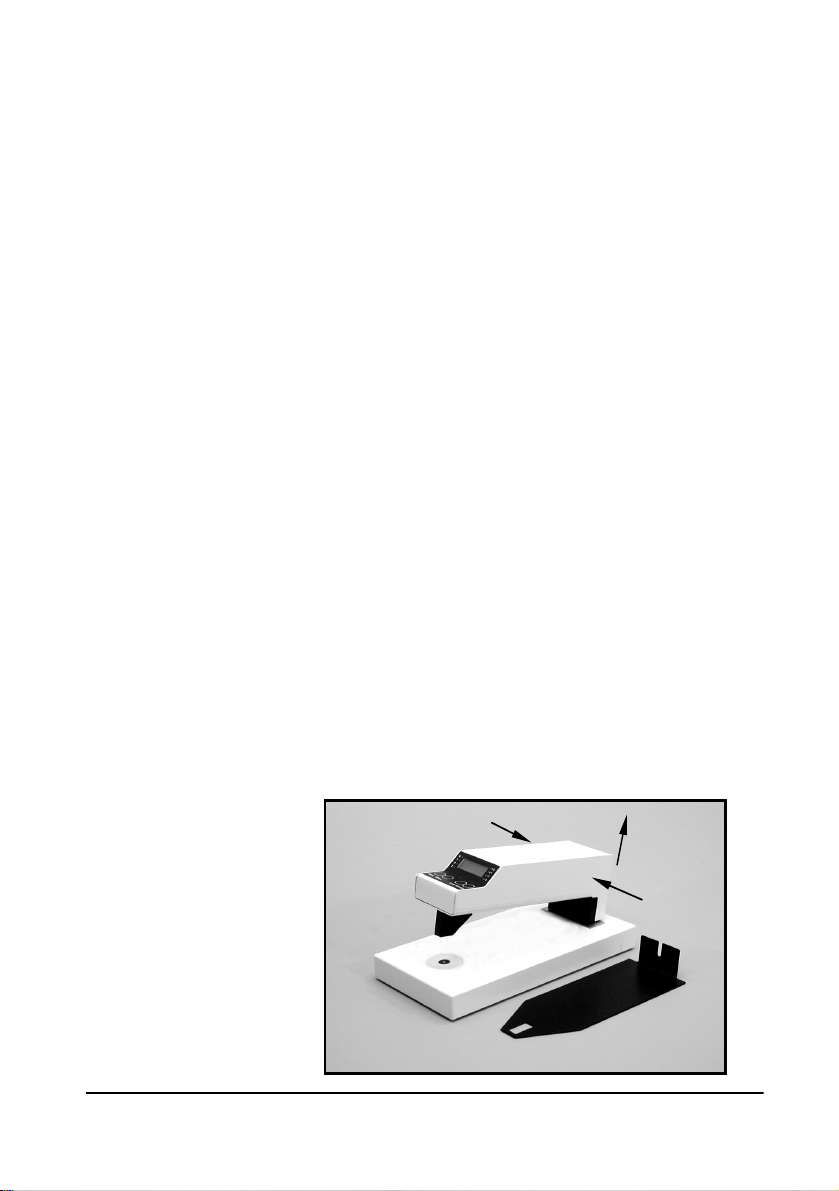
Option 01: Removable measuring head
The removed head is used for reflection measurement only! The
measuring head, when attached to the base unit or the additional
base plate, is kept in correct alignment only, when the screw with the
black knob on the rear side is tightened. For measurement of large
murals the head is easily removed from the body and then attached
to a base plate with an integrated target. The electrical connection is
made with a long or a short cable.
Measuring large prints:
§ Turn the instrument so, that the long side is right in front of you.
§ Remove the cable between the base unit and the measuring
head.
§ Loosen the screw on the rear side of the instrument by turning the
black knob.
§ Grip the back part of the measuring head in direction "A".
§ Pull the measuring head in direction "B" off the base unit and stick
it onto the additional base plate. Keep attention that the vertical
part of the base plate slips into the slot of the measuring head
(between case and bear).
§ Tighten the screw with the black knob. Use no tool.
If you attach the head to the base unit later on please connect the
cable again, otherwise the transmission lamp will not work.
Figure 3: Moving the
measuring head
B
A
TRD 2 USER MANUAL Version 6.2 7
Page 8

Option 02: Changeable apertures
The apertures have 4 different diameters (0.5/1/2/3mm). Like the
standard diffuser they are made out of opal material. Smaller
diameters reduce the amount of light, thus the maximum density is
lowered. The aperture is changed by pressing slightly on the edge of
the diffuser, e.g. with the fingernail. After changing the aperture, new
reference points must be set for transmission mode.
Option 03: PC port
To connect the densitometer to a PC, use the optional USB connector
and cable. See appendix for details.
Option 05: Extended transmission density range
The maximum density in transmission mode is extended to 5,5 log.D.
Option 06:
The resolution of the instrument is increased to 0.001 log.D in the
measurement range between –0.999 and +0.999 log.D.
5. Installation
5.1 Location conditions
§ Store and use this instrument only in rooms with a temperature
from 17°C to 27°C (degree Celsius) and relative humidity from 0
to 70 percent.
Fast temperature variations may cause condensation inside the
densitometer or the power supply. After moving the instrument
from a cold to warm environment (more than 10°C temperature
difference) please wait at least one hour until you connect the
power supply again.
§ Keep the densitometer away from these environment:
- Direct Sunlight
- Instruments that emit heat
- Aggressive chemicals or liquids
- Strong magnetic fields, e.g. from transformers, voltage
stabilisers or loudspeakers
- Electronic devices that emit strong interference’s, like dimmers
8
Page 9

5.2 Switching on
§ Assure that the main voltage of the power supply unit is the same
as the one indicated on the identification label of this unit.
§ Connect the power supply first to the densitometer and then into
the wall plug
§ The instrument switches on automatically in a stand by mode.
Wait at least 2 minutes before taking the first reading.
.
6. Reading
Caution: Always depress the measuring head softly until it stops on
the reading-area.
To prevent damage of the precise bearing, always let the measuring
head return slowly to the "up" position! Never try to raise it higher
than this stop position!
On a digital display, the actual value may intermit between two
values. The display changing back and forth between two values
should not be a cause for concern.
6.1 Instructions to avoid incorrect reading
§ Especially when measuring high densities the subject must be
free from dust, lint, finger prints, and other contaminants.
§ The right reading mode is very important: "Transmission" for film,
glass plates or filters. "Reflection" for non-transparent subjects
(i.e. pictures) The wrong mode causes considerable errors.
§ The densitometer can also be used for process control with B&W
images on colour-based film (i.e. silver-free films), if no colourextracting filter is required.
§ Thick glass plates or filters should be read in low ambient light
because of their light conducting tendency.
§ Films should be placed on the reading area with the emulsion
side down.
TRD 2 USER MANUAL Version 6.2 9
Page 10

6.2 Instructions for reset to zero
Reset the display before starting a series of density measurements. If
the part of the subject used for zeroing does not have the lowest
density, a negative sign will appear while measuring lower density.
Reset of transmission reading
§ In photographic applications you may decide either to measure
the density in relation to the absolute light or to base+fog. That is
an unexposed, but a developed area of film.
- If you zero to absolute light (no film in the light pass), the
base+fog is displayed with a positive value and this value has to
be subtracted from all density values.
-If you zero to base+fog, the density values of any area within the
negative could be read direct. The absolute value of base+fog
could also be measured, while taking a reading to absolute light
and ignoring the negative sign in this case
§ If in thick glass plates or filters zeroing to the light source is
required, then the subject to be read must be placed on the
reading area so that the light source is not covered up, but the
measuring head rests on the plate when the measuring head is
depressed. The free light flux is equivalent to absolute-zero.
Reset of reflective reading
§ There is no totally reflective and diffusing material i.e. there is no
absolute white. Barium sulphate is used for zeroing, because it
reflects up to 99% of diffuse incident light, however, it is also
sensitive to soiling and damage. Normally, the back of a fibre
based paper is sufficient for zeroing.
§ In photography, zeroing is done on the base fog, that is an
unexposed but developed part of the subject.
§ If occasionally material thicker than 2 mm is to be measured, then
the material and the paper used for zeroing should be placed
under the measuring head together to allow for the offset in the
reading geometry. This hint can be ignored, if you're working with
the removed measuring head (Opt.01).
10
Page 11

6.3 Density measurement
Transmission reading
§ If the instrument is not in mode 'T' select this mode by pushing the
"T/R" button.
§ Reset to zero on base fog. Position film so that the lightest part is
centred over the light source. Depress measuring head and press
"Min" button until display reads 0.00.
§ Measurement is done by slightly lowering the measuring head
until light comes on, then centring the area to be read over the
light source and reading the value with the fully depressed
measuring head.
Reflective reading
§ If the instrument is not in mode 'R' select the mode by pushing the
"T/R" button.
§ Place subject in a way that the area to be read is centred under
the tip of the measuring head. Press "Min"-button until display
reads 0.00.
§ Take series of readings.
TRD 2 USER MANUAL Version 6.2 11
Page 12

7. Care of instrument
§ The housing and especially the reading area should only be
cleaned with a lightly dampened soft cloth or chamois, if
necessary with the addition of a mild cleaner
§ Do not use solvents or abrasive materials.
§ The measuring head and probe should only be cleaned from dust
with a soft brush or compressed air.
§ Unplug the instrument when not in use for long time periods.
§ For necessary repairs send the densitometer and the power
supply unit to manufacturer or authorised service centre. Any
unauthorised opening, will invalidate your guarantee.
§ CAUTION: To prevent an electric shock do not open the
instrument! There are no user serviceable parts inside!!
8. Calibration check
The instrument is calibrated at the factory. Certification is shipped
with the instrument in the form of a transmission and a reflective light
calibration strip on which the density values of the calibration are
recorded.
Note: The densitometer and the calibration strips shipped with it
belong together. Since measuring geometry may differ, the calibration
strips should not be used to check an other densitometer.
The calibration strips are made of photographic material. They should
be kept in a dark, cool, dry, and dust-free place to protect density
values. Do not touch reading area with bare hands. Soiled reading
areas cause incorrect readings, especially on high densities.
12
Page 13

Calibrating should be done under the following conditions:
§ Ambient temperature 20 to 22 ° Celsius.
§ Relative humidity between 0 and 70 %
§ Voltage and frequency must be in tolerance to the one indicated
on identification label.
§ The instrument should be acclimated to ambient conditions and
have been connected to the power source for a minimum of 5
minutes before calibrating.
§ For calibrating procedure use the aperture with 3mm diameter
(Opt.02 only).
§ Position the calibration strip so, that the left field (0,00) of it is
centred over the light source. Reset the display to zero.
§ Reading of densities is done in the centre of each test area. If a
slight drifting of values is encountered, the values should be
averaged.
§ The tolerance is ± 0.02 log. D. If greater variations are
encountered, the TRD and the calibration strip should be sent to
the manufacturer, or authorised service centre, since a new
calibration is not possible without the necessary testing devices.
9. Guarantee
This instrument is fully guaranteed for the period of one year from
date of purchase. Proof of purchase is the invoice or receipt.
Damages due to improper handling or unauthorised access are
excluded.
This instrument has been carefully manufactured and tested using
defect free materials and state-of-the-art technology.
In case of a failure the instrument should be returned free of charge
to the manufacturer or authorised service centre accompanied by
proof of purchase.
For the warranted period, the manufacturer will pay cost of
replacement parts and repair. However, the manufacturer reserves
the right to exchange the instrument. Important: Both the instrument
and calibration strips must be send back together!
TRD 2 USER MANUAL Version 6.2 13
Page 14

10. Technical data
§ Dimensions length x width x height : 200 x 100 x 100 mm
§ Weight : 1 kg
§ Voltage requirements : 12 V DC by use of a wall
plug power supply
§ Power consumption : 3 VA
§ Aperture diameter : 0,5/1/2/3 mm
according to the order
§ Reading geometry
Transmission : diffuse/directed
Reflection : 45/0 degrees
Opt.04 : polarised
§ Maximum subject size
Width x Height : 260 mm x 2 mm
Opt. 01 : 2m Radius
§ Maximum measurable density
Transmission aperture. ∅ 3,0mm : 4,0 D
∅ 2,0mm : 3,5 D
∅ 1,0mm : 3,0 D
∅ 0,5mm : 2,5 D
Transmission Opt. 05 : 5,5 D
Reflection : 2,5 D
§ Reading variation : ±(1% + 0,02 log.D.)
§ Repeat accuracy : ± 0,01 D
§ Temperature range : 17 ... 27 °C
§ Relative humidity : 0 ... 70 %
§ Accessories : Power supply unit
Two calibration strips
14
Page 15

Appendix: Communication parameters
§ Communication port type: USB 2, emulating a serial com port with
9600 Baud, 8 Databit, 2 Stopbit.
§ Character which are send to the densitometer are answered with
the character NAK (15h).
§ The measurement value is transmitted automatically by the
instrument every time there is a stable value for at least 0,5
seconds. The value is transmitted with the following syntax:
Character-No. possible Char. meaning
1 T/R/0 Trans./Refl./StandBy
2 +/- Sign
3 0...9/. Value MSB
4 0...9/. Value
5 0...9/. Value
6 0...9/. Value LSB
7 D/Z/% Density/Zone/Percentage
of dot area
8 CR End of string
Examples:
T+1.53D Transmission
Density: +1.53 log D
R-0.05D Reflective
Density: -0.05 log D
T+05.7Z Transmission
Zone: 5.7
R+45.0% Reflective
45 Percent of dot area
T+.278D Transm. in case of Opt.06
Density: +0,278 log D
0+....D Stand By mode or
measuring head is up
Issue date: January 2007
Technical data may change without notice.
TRD 2 USER MANUAL Version 6.2 15
Page 16

Heiland electronic GmbH
Schulstraße 8
D-35579 Wetzlar
Telefon: ++49 6441 26978
Fax: ++49 6441 26988
 Loading...