

Heidolph Hei-VAP Expert, Hei-VAP Ultimate Control, Hei-VAP Ultimate, Hei-VAP Expert Control Operating Manual
Page 1
Intelligent
Evaporation
Leading Safety Standards Superior Ease of Use Reduced Cost of Ownership
Operating Manual 2
Rotary Evaporator Hei-VAP Expert, Hei-VAP Expert Control,
Hei-VAP Ultimate, Hei-VAP Ultimate Control
Operating manual must be read before initial start-up.
Please follow the safety instructions provided.
Please keep for future reference.
Original-Betriebsanleitung 100
Rotationsverdampfer Hei-VAP Expert, Hei-VAP Expert Control,
Hei-VAP Ultimate, Hei-VAP Ultimate Control
Betriebsanleitung vor Erstinbetriebnahme unbedingt lesen.
Sicherheits hinweise beachten.
Für künftige Verwendung aufbewahren.
Page 2

Operating Manual
ContentsContents
About this Document 4
Version and variants ...........................................................................................4
About this manual ..............................................................................................4
Symbols and keywords ........................................................................................5
Contents
Safety instructions 6
General safety instructions...................................................................................6
EU Declaration of Conformity .........................................................................6
Intended use...............................................................................................6
Installation / electrical safety ........................................................................7
Personnel training ........................................................................................7
Operator duties ..................................................................................................7
Installation site ...........................................................................................7
Modications to the device ............................................................................8
Employee safety ..........................................................................................8
Safety during use ...............................................................................................8
Disposal ............................................................................................................9
Device description 10
Device overview ...............................................................................................10
Overall view Hei-VAP Expert, Hei-VAP Expert Control ......................................10
Overall view: Hei-VAP Ultimate, Hei-VAP Ultimate Control ...............................11
Control box (for control variants only) ..........................................................13
Control panel: Hei-VAP Expert, Hei-VAP Expert Control ...................................13
Control panel: Hei-VAP Ultimate, Hei-VAP Ultimate Control .............................. 14
Start-up 15
Setting up the device ........................................................................................15
Connecting/disconnecting the power cord ............................................................15
Remove transportation lock................................................................................15
Switching the device on and o ..........................................................................16
Heating bath and ask lift ..................................................................................16
Basic Settings ..................................................................................................19
Menu navigation ...............................................................................................21
Overview of the menu tree ..........................................................................21
Operation of the menu ...............................................................................23
Changing the basic settings ...............................................................................26
Language and formats ................................................................................26
Date and time ...........................................................................................26
Settings ...................................................................................................27
Applications ..............................................................................................30
Symbols used ..................................................................................................31
Operation 35
Process sequence .............................................................................................35
Selecting an application ..............................................................................35
Recording process times .............................................................................37
Applications .....................................................................................................38
Setting parameters manually (“Application Basic”) .........................................38
Using and managing favorites (Application “Extended”) ..................................42
Using and managing ramp proles (Application “Extended”) ............................46
Page 3

Contents
Using automatic mode DAA (Application “Extended“) ......................................51
Starting an application with a timer ..............................................................53
Interfaces ........................................................................................................54
Evaporating and receiving asks .........................................................................55
Assembling and removing the evaporating ask .............................................55
Assembling and removing the receiving ask .................................................56
Ventilation .......................................................................................................56
Cleaning and Maintenance 57
Cleaning ..........................................................................................................57
Maintenance ....................................................................................................58
Troubleshooting 59
Malfunctions and remedies .................................................................................59
Resetting temperature limiter .............................................................................66
Assembly 67
Electrical connections ........................................................................................67
Installation ......................................................................................................68
Assembly parts ..........................................................................................68
Transportation lock ....................................................................................70
Heating bath .............................................................................................70
Control panel ............................................................................................72
Vapor tube ................................................................................................73
Condenser ................................................................................................75
Evaporating ask: Angle and immersion depth ...............................................80
Control box ...............................................................................................82
Vacuum manifold .......................................................................................82
Attaching the peripheral devices .........................................................................83
Connecting vacuum....................................................................................83
Cooling water connection ............................................................................87
Optional accessories .........................................................................................88
Dismantling and Storage 92
Dismantling, transportation and storage ..............................................................92
Dismantling ..............................................................................................92
Transportation and storage .........................................................................93
Spare parts and accessories 94
Scope of delivery ..............................................................................................94
Accessories ......................................................................................................94
Software copyright ....................................................................................95
Appendix 96
Technical data ..................................................................................................96
Service 97
Contact / Technical Service ................................................................................97
Warranty .........................................................................................................98
Declaration of no objection ................................................................................99
Page 4

About This Document
Copyright
This operating manual is protected by copyright and is exclusively intended for the
internal use of the purchaser.
Handing over this operating manual to third parties, reproducing it in any type or form
–in part or in full – and utilizing and/or communicating its contents is prohibited without
prior written approval from the manufacturer.
Any violations will result in an obligation to provide compensation for damages. Other
claims remain unaected.
About this Document
Version and variants
Version
This manual describes the function, operation and maintenance of the Hei-VAP Expert
and Hei-VAP Ultimate rotary evaporators.
Version Alteration date
1.0 04/2019
Variants
The device is available in dierent variants. Certain features or functions are only
available in specic product variants. These variants are described in this operating
manual.
About this manual
This operating manual is an integral part of the device described here.
➜ Carefully read through this operating manual and observe all of the
safety instructions and warnings notices.
➜ Ensure that every user has carefully read the operating manual
before using the device for the rst time.
➜ Store this operating manual so that it is accessible to all users at
all times.
➜ Pass the operating manual on to any subsequent owner.
The current version of this operating manual can also be found at:
https://heidolph-instruments.com/en/service/downloads/operation
manuals#Rotary Evaporators (Hei-VAP Expert, Hei-VAP Ultimate)
In addition, also observe the local regulations at the installation site.
4
Page 5
About This Document
Symbols and keywords
Standardized symbols and signal words are used in this operating manual to warn against
any dangers and provide important instructions. These instructions must be strictly
observed to avoid accidents and damage.
The following terms and basic symbols are used:
Symbol Additional signal words / explanation
Warning
signs
Prohibitory
signs
Mandatory
signs
Other symbols used:
Symbol Description
➜
✓
▪
The yellow triangle indicates hazardous situations. It is used in combination with the following signal words:
DANGER:
Indicates a hazardous situation which, if not avoided, will result in
serious injury or death.
WARNING:
Indicates a hazardous situation which, if not avoided, may result in
serious injury or death.
CAUTION:
Indicates a hazardous situation which, if not avoided, may result in
property damage and minor or moderate injury.
Prohibited:
The red circle indicates a situation that should be avoided under all
circumstances and which, if not avoided, may result in serious injury
or death.
Must be observed:
The blue circle indicates important information. Please observe this
information to avoid any property damage.
Handling instruction, action required
Result of action
List of information
▪
▪
a.
b.
c.
List of variants
5
Page 6

Safety Instructions
General safety instructions
Safety instructions
EU Declaration of Conformity
This device complies with the following EC-Directives*:
▪ 2006/42/EC Machinery Directive
▪ 2014/30/EU Electromagnetic Compatibility Directive
* See also the attached “EU Declaration of Conformity”.
This device was tested according to the following Directives:
▪ UL 61010-1 :2012/R:2016-04
CAN/CSA-C22.2 No. 61010-1:2012/U2:2016-04
▪ UL 61010-2-010:2015
CAN/CSA-C22.2 NO. 61010-2-010:2015
The device has been manufactured according to state-of-the-art technology and in
compliance with recognized safety regulations. However, risks may still arise during
installation, operation and maintenance.
➜ Please ensure that the operating manual is available at all times.
The device may only be used under the following conditions:
➜ Only operate the device if it is in a technically perfect condition.
➜ Only operate the device if you are properly aware of the risks and required safety
measures.
➜ Only operate the device in accordance with the instructions given in this operating
manual.
➜ If any information is ambiguous or missing, ask your superior or contact the
manufacturer.
➜ Do not operate anything on the device without authorization.
➜ Only use the device in accordance with its intended use.
Intended use
The device may only be operated by authorized personnel.
The device is suitable for the
following uses:
The device may be operated
in research laboratories,
other laboratories and
production facilities in the
following sectors:
Improper use / Foreseeable misuse
Any use which deviates from the device’s intended use is considered to be improper. The
manufacturer is not liable for damage that occurs as a result. The risk is borne by the
operator alone.
In case of application in the medical and food sector, the operator is solely responsible for
observing the regulations and standards pertaining in each case.
▪ Distillation to separate substances
▪ Concentration
▪ Crystallization
▪ Powder drying
▪ Chemistry
▪ Pharmacy
▪ Biology
▪ Environmental analytics
▪ Basic research
▪ Similar research laboratories
6
Page 7

Safety Instructions
Installation / electrical safety
▪ The device may only be connected up if the available power supply voltage corre-
sponds to the information stated on the rating plate for the device.
▪ The power supply connection must be easily accessibly at all times.
▪ An RCD circuit breaker (residual current circuit breaker) must be tted to the
electrical system in the building so that the device is disconnected from the power
circuit in the event of a fault.
▪ Repairs may only be performed by electricians authorized by Heidolph Instruments.
▪ Never operate the device with a damaged power cord.
▪ Always turn the device OFF and disconnect the power cord before carrying out any
maintenance or repair work.
Personnel training
▪ The device may only be operated by trained personnel.
▪ The device may only be operated by persons who have been instructed and super-
vised in its proper use by trained specialist personnel.
▪ The device may only be operated by specialist personnel who are the legal minimum
age or above.
▪ Other persons may only work on the device under the constant supervision of experi-
enced and trained specialist personnel.
▪ This operating manual must be read and understood by all persons working with the
device.
▪ Personnel must receive safety training that ensures responsible and safe work
practices.
Operator duties
Installation site
▪ The device must be installed in a suitable location.
▪ The device must be installed on a rm, stable and temperature-resistant surface.
▪ Ensure that the device and all of its components are easily accessible at all times.
▪ Maintain a sucient safety clearance to, in particular, any moving and/or hot
equipment components.
▪ It is not permitted to place or store any objects such as accessories, tools or
chemicals within this distance area during operation.
▪ All screw connections must be securely tightened.
▪ It is not permitted to operate the device near to highly ammable or explosive
substances.
▪ Operate the device in conjunction with a closed extractor hood if working with poten-
tially harmful media (see DIN EN 14175 and DIN 12924).
7
Page 8

Safety Instructions
▪ The device is designed for indoor use only under the following ambient conditions:
Ambient temperature 5 - 31 °C at 80% relative humidity
32 - 40 °C decreasing linearly to a
maximum 50% relative humidity
Installation altitude 0 - 2,000 m above sea level
Contamination level 2
Overvoltage category II
Permissible supply
deviations
▪ If the device is operated in corrosive atmospheres, the service life of the device will
decrease depending on the concentration, duration and frequency of the exposure to
the corrosive atmosphere, e.g. concentrated hydrochloric acid (HCl)
± 10 %
Modications to the device
▪ It is not permitted to make any unauthorized modications or changes to the device.
▪ Do not attach or install any parts that have not been approved by the manufacturer.
▪ Unauthorized modications or changes will void the EC Declaration of Conformity for
the device and operation of the device will no longer be permitted.
▪ The manufacturer is not liable for any damage, dangers or injuries that result from
unauthorized modications and changes or due to the non-observance of the instructions in this manual.
Employee safety
➜ Ensure that the device is only operated by qualied specialist personnel and trained
employees.
➜ Comply with the following instructions to avoid any personal injuries and property
damage:
- Laboratory regulations
- Accident prevention regulations
- Hazardous Substance Act
- Other generally accepted occupational health and safety regulations
- Local regulations
Safety during use
➜ Wear the appropriate clothing when working on the device (protective clothing, safety
glasses and, if necessary, safety gloves).
➜ Do not use the device in potentially explosive areas. The device is not protected
against explosion. There is no explosion or ATEX protection available.
➜ Do not carry out work with exposed ames in the vicinity of the device (risk of
explosion).
➜ Do not operate or assemble devices in the vicinity which are emission or radiation
sources (electromagnetic waves) for the frequency range (3*10
➜ Do not operate or assemble appliances in the vicinity of the device which constitute
emission or radiation sources for ionizing radiation or in the ultrasonic range.
➜ Do not operate the device where adiabatic compression or shock waves might occur
(shock wave combustion).
8
11
Hz to 3*1015 Hz).
Page 9
Safety Instructions
➜ Do not use materials which pose a potential risk of uncontrolled energy release which
might result in pressure increase (exothermic reaction; spontaneous combustion of
dusts).
➜ Do not work with hard, brittle materials (such as stones, soil samples, etc.) which
could result in the destruction of the evaporating ask.
➜ Use only heating bath uids which guarantee suitable heat transfer.
➜ Do not operate the device with excess pressure.
➜ Limit the pressure dierence for glass components to a maximum of 2 bar.
➜ Do not increase the maximum excess pressure of the cooling uid above 2 bar.
➜ Wear safety gloves and safety glasses when working with coolants in very low
temperature ranges, such as with dry ice.
➜ Do not increase the ow speed of 1 m/s while siphoning liquids in with combustible
materials (electrostatic charge; risk of ignition).
➜ Eliminate the production of gases classied in explosion group IIC during distillation
by materials or due to chemical reactions, such as hydrogen.
➜ Do not use distillation material where the distillation residue might be explosive.
➜ Only connect clean ground joints.
➜ Attach ground joints securely in order to connect them leak-tight.
➜ Attach all tube connections securely to ensure safe operation.
➜ Connect all cables and tubes without kinks and locate them outside the operating and
danger zone.
➜ Avoid putting pressure on the display when you are not operating the device.
➜ Do not spill liquids on the device or any parts of it.
➜ Wipe up any accidentally liquids spilled on the device immediately.
➜ Correct errors immediately.
➜ Do not use abrasive material to clean the glass surface. Wipe only with a damp cloth.
➜ Always switch the device OFF after use.
Disposal
Caution:
Possible environmental damage!
The device contains a CR2032 lithium button cell battery with the as
per IEC-2. Batteries must be disposed of separately pursuant to the
European Batteries Directive.
When disposing of the device, make sure that the waste management facility takes part in the joint return system for batteries or
has specically established and practices an approved return system
according to the Battery Directive 2012/56/EU.
➜ Check the device components for hazardous substances and
solvents.
➜ Clean all components before disposal.
➜ Dispose of the device in accordance with the relevant national
regulations.
➜ Dispose of the packaging material in accordance with the appro-
priate national regulations.
9
Page 10
Device Description
Device overview
Device description
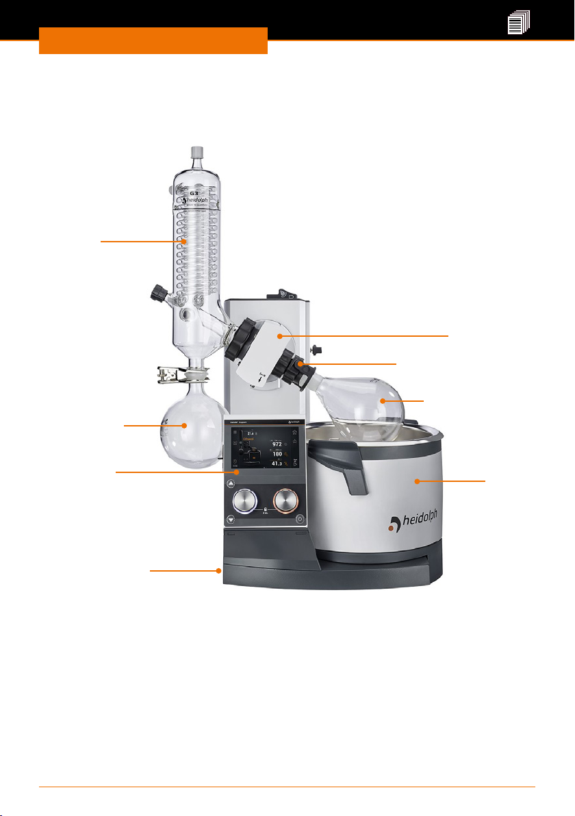
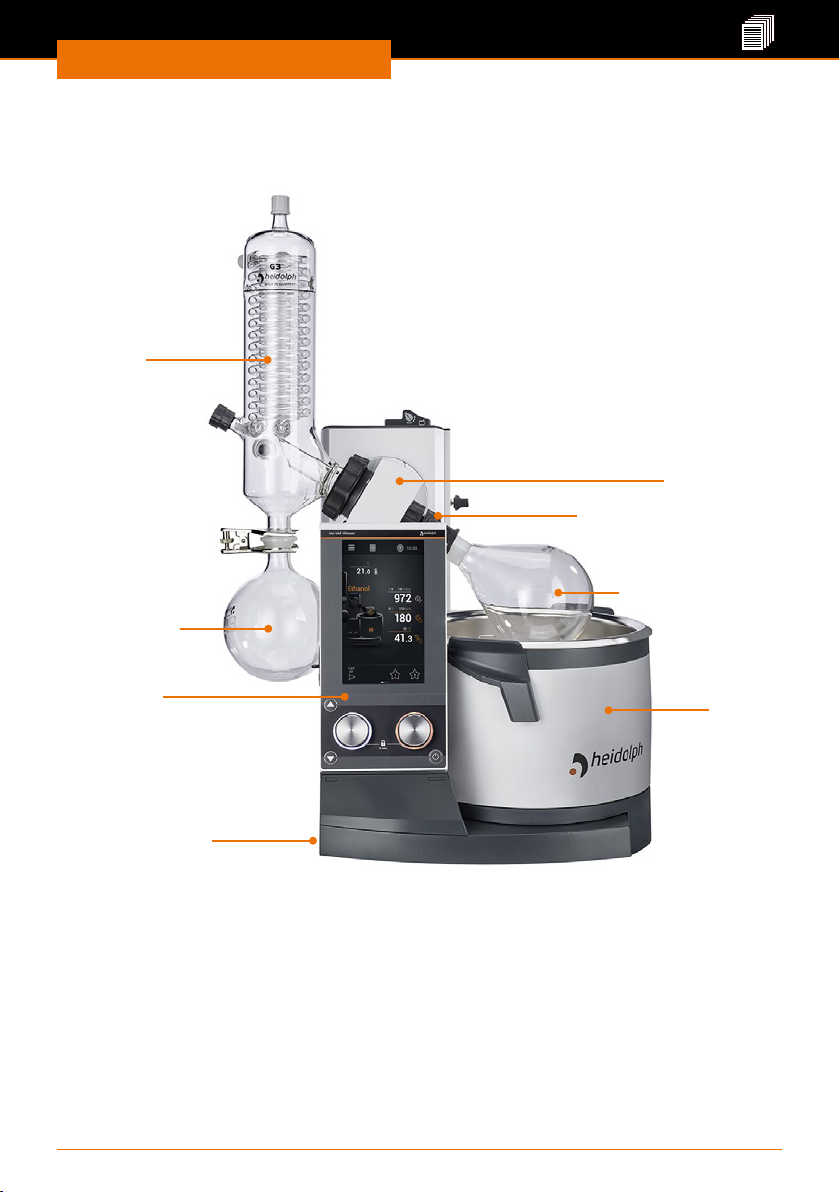
Overall view Hei-VAP Expert, Hei-VAP Expert Control
Condenser
(example)
Flask drive
Easy Clip ask clamp
Evaporating ask
Receiving ask
Control panel
Heating
bath
ON/OFF switch
10
Page 11
Device Description
Overall view: Hei-VAP Ultimate, Hei-VAP Ultimate
Control
Condenser
(example)
Flask drive
Easy Clip ask clamp
Evaporating ask
Receiving ask
Control panel
ON/OFF switch
Heating
bath
11
Page 12
Device Description
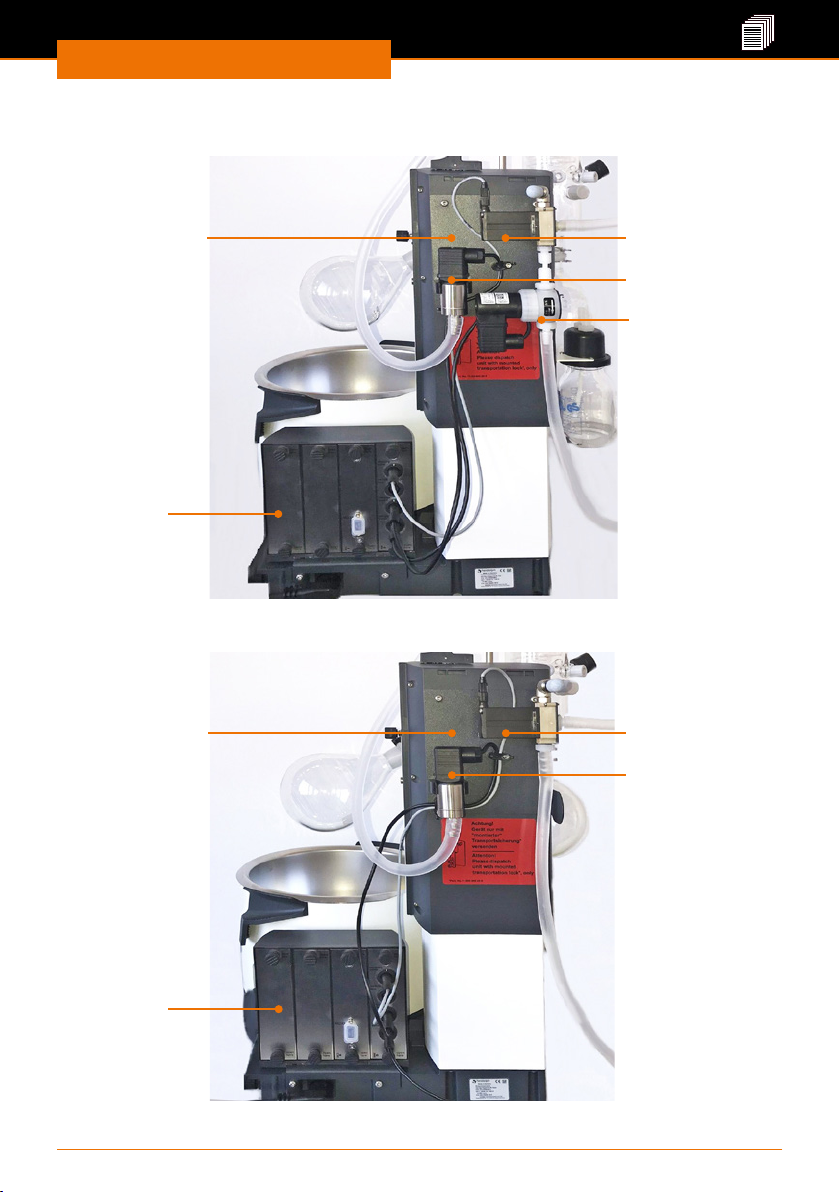
Back side of the device (control variants): valve-controlled pumps / house
vacuum:
Vacuum manifold
with components
for
vacuum control
Control box
Back side of the device (control variants): speed-controlled pumps:
Vacuum manifold
with components
for
vacuum control
Ventilation valve
Ventilation valve
Vacuum sensor
Vacuum valve
Vacuum sensor
Control box
12
Page 13

Device Description
Control box (for control variants only)
Connections for:
Blank panels for
possible extensions
RS-232 interface
(chiller connection)
Ventilation valve
Vacuum sensor
Vacuum valve
Control panel: Hei-VAP Expert, Hei-VAP Expert
Control
(Example display start page) The control panel is touch-sensitive
Switchbox
Vapor temperature
Open menu for basic
settings
Changing the
operating mode
Time display:
Stopwatch,
switching to timer/
clock
up
Lift buttons
(only for
motor lift
devices)
down
Rotary knob left:
Adjust rotation
* Conguration of rotary knob assignments is possible.
Set and read process parameters
13
Quick selection
favorites
Maintaining the
vacuum
Start / stop all
functions (except
chiller)
Standby button
Rotary knob right: Adjust heating
bath temperature or vacuum*
Page 14
Device Description
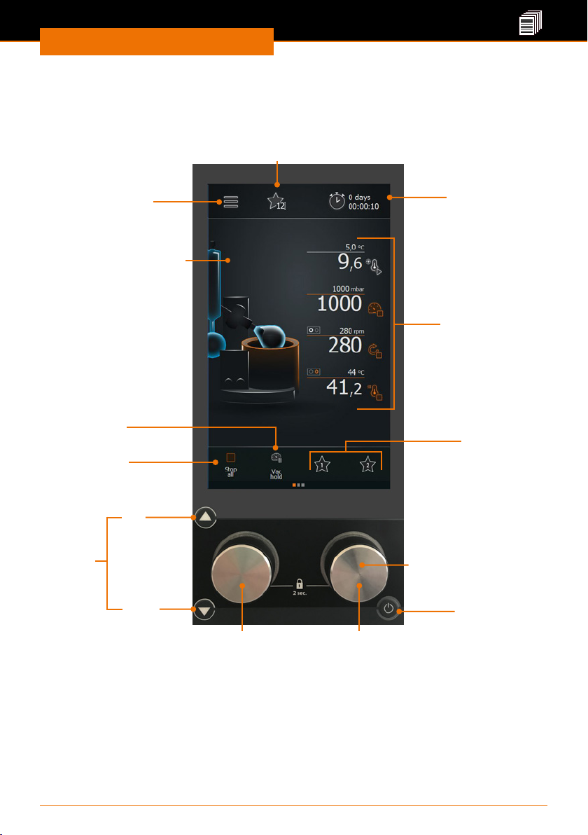
Control panel: Hei-VAP Ultimate, Hei-VAP Ultimate
Control
(Example display start page) The control panel is touch-sensitive
Changing the operating mode
Time display: Set
Open menu for basic
settings
Vapor temperature
Maintaining the
vacuum
Stop/start all
functions
(except chiller)
time, switch to timer /
stopwatch
Set and read
process parameters
Quick selection
favorites
up
Lift buttons
(only for
motor lift
devices)
down
Rotary knob left:
Adjust rotation
* Conguration of rotary knob assignments is possible.
14
Standby button
Rotary knob right: Adjusting
heating bath temperature or vacuum*
Page 15
Device Description
Setting up the device
Warning:
Risk of slipping for the device!
Due to an unsuitable surface or as a result of vibrations generated
during the operation the device may tilt or start moving and slide o
the table top.
The installation surface must be smooth, level, clean and temperature
resistant. Avoid shaking and impact forces on the device as well as at
the installation surface.
➜ Set up the device on a solid, smooth, level and temperature-resistant surface.
➜ Clean installation surface and feet o the device with a damp cloth and ethanol
regularly.
Start-up
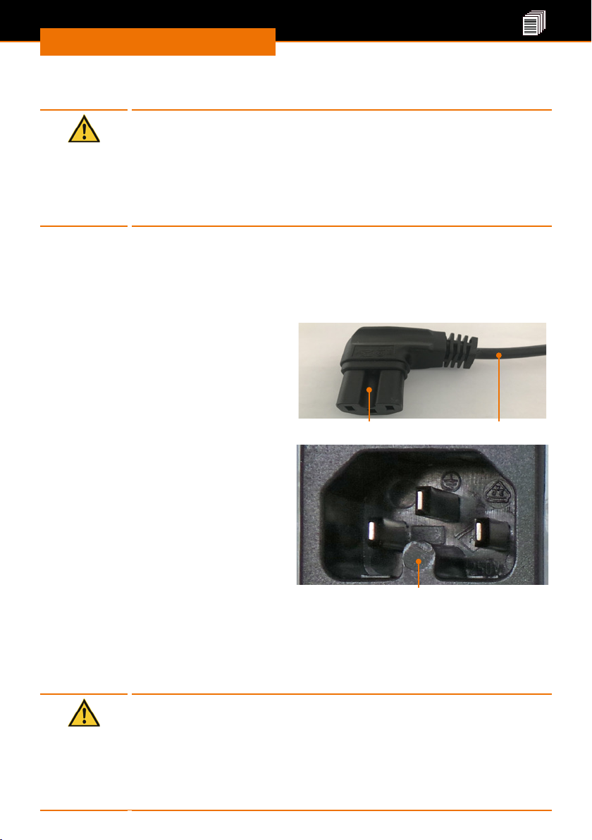
Connecting/disconnecting the power cord
Connecting the power cord
The power cord has a three-pole connector
and a recess on its bottom side.
Power cord connector
The device socket is located on the back
side of the device.
➜ Insert the power cord connector into
the device socket with the recess
pointing downwards.
✓ The connector has been securely
inserted when it has been pushed in up
to the stop.
➜ Now insert the power cord plug into the
power socket.
Disconnecting the power cord
➜ First, remove the plug from the power socket.
➜ Then disconnect the power cord connector from the device.
Device socket
Power cord
Remove transportation lock
Caution:
Possible damage to the device (motor lift variants only)
Switching the device on before the heating bath and the control panel
are connected can cause malfunctioning of the electronics the moment
the transportation lock is removed.
Prior to switching on the device for the rst time, remove the transportation lock exactly in the order given in the instructions (see chapter
“Assembly”, section “Transportation lock”).
15
Page 16
Start-up
Switching the device on and o
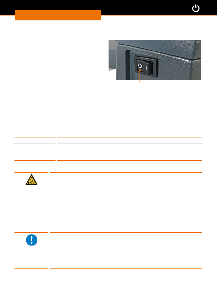
The ON/OFF switch is located at the lower
left side of the device.
Switching the device on
➜ Press the ON/OFF switch on the left
side.
✓ The currently set values will appear on
the display.
✓ The device is switched on.
Switching the device o
➜ Press the ON/OFF switch on the left side.
✓ The display will go blank.
✓ The device is switched o.
ON/OFF switch: OFF
Heating bath and ask lift
The heating bath can be lled with dierent heat transfer uids, e.g.,
20° C to 90° C tap water
20° C to 170° C polyethylene glycol (e.g. Budde heating bath uid)*
150° C to 210° C silicone oil with low viscosity (40 cP), ashpoint > 285 °C
* see chapter “Spare Parts and Accessories, Accessories”.
e. g. Wacker AP 200 silicone oil)*
Danger!
Risk of explosion!
Heating bath uid oil with a ash point < 285 °C could catch re at
high heating bath temperatures and lead to uncontrolled thermal reactions and possible explosion.
➜ Use only oil with a ash point > 285 °C.
The markings in the heating bath indicate the minimum and maximum liquid levels for
the immersed evaporating ask.
The evaporating ask is moved up and down using a lift and is immersed in the heating
bath in this manner.
When the lift moves downward, the evaporating ask displaces the
already lled in water or oil.
To prevent the heating bath from overowing:
▪ Prior to lling, move the lift with the mounted evaporating ask
downward.
▪ Only then ll the water or oil up to at most the upper mark of the
heating bath container.
16
Page 17
Start-up
1. Flask lift
Immersing the ask lift
Immerse the ask in the heating bath only so far that it does not touch
the edge or the bottom.
For adjusting the immersion depth and ask angle, see Chapter
“Assembly”, Section “Evaporating Flask: Angle and immersion depth”.
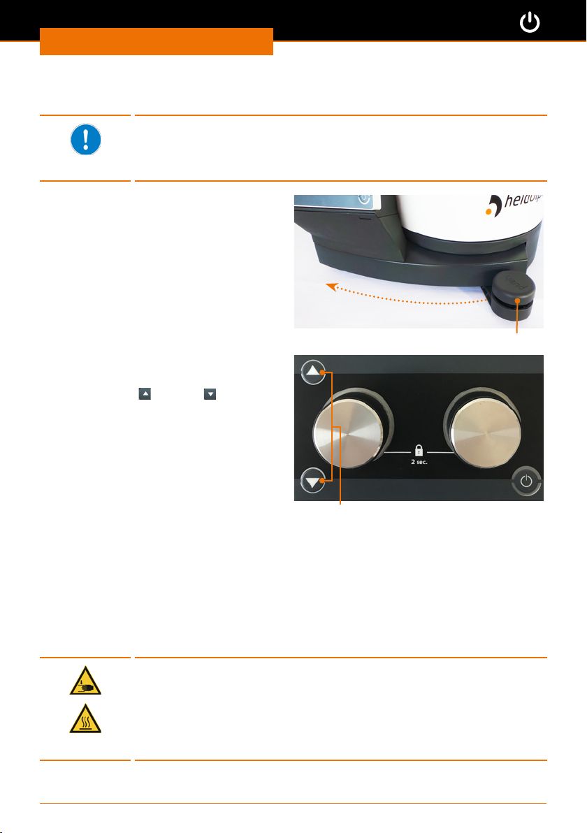
Immersing the ask: Manual lift
➜ Press the manual lift lever downward.
➜ While pressed, move the manual lift
lever to the left for lowering or to the
right for raising.
➜ Release the manual lift lever at the
desired position.
✓ The manual lift locks in the corre-
sponding position.
Immersing the ask: Motor lift
✓ The device is switched on.
➜ Press the up
➜ Release the lift button at the desired
ask position.
✓ The motor lift will stop.
You can also set that the ask is automatically lowered at the start of the processes
(see Section “Settings”).
or down lift button.
Manual lift lever: Lift position top
Lift buttons: up, down
2. Heating bath
Filling the heating bath
✓ The evaporating ask is immersed in the heating bath at the correct position.
➜ Fill the heating bath with the heating uid at most up the upper mark.
✓ The liquid level is within the minimum and the maximum mark.
Connecting the heating bath
Warning:
Risk of crushing! Risk of burns!
If the device is switched on, the heating or rotation can be started
unintentionally. This may injure and burn your hands.
Connect the heating bath to the device base only when the device is
switched o.
17
Page 18
Start-up
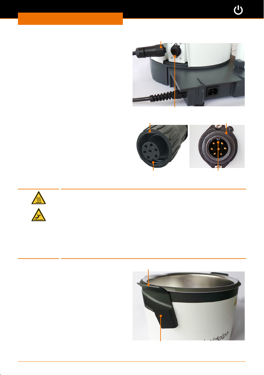
The heating bath plug is located on the
rear right of the heating bath.
✓ The device is switched o.
✓ The heating bath is locked in place on
the base plate.
➜ Insert the 7-pin connector socket with
the recess pointing upward into the
heating bath plug.
➜ Tighten the union nut clockwise to the
right.
Emptying the heating bath
Warning:
Risk of scalding! Risk of slipping!
When emptying the heating bath, you may burn yourself or slip on
spilled uid.
Before emptying heating bath:
▪ Wear protective clothing.
▪ Switch the device o.
▪ Wait until the heating bath uid has cooled below 50 °C.
▪ Disconnect device base and heating bath.
▪ Remove evaporating ask.
▪ Lift the heating bath only at the insulated handles.
Heating bath connector socket
Heating bath plug
Union nut Heating bath plug
Recess
Feather
✓ The device is switched o.
✓ The evaporating ask has been
removed.
➜ Turn the union nut on the heating bath
connecting cable to the left in counterclockwise direction until it is released.
➜ Disconnect the connector socket
contact from the heating bath.
➜ Put your thumbs on the ribbed
surfaces of the handles and then clasp
them completely.
➜ Carefully lift the heating bath at both
handles and empty it.
Protective lip
Heating bath handle
18
Page 19
Start-up
Basic Settings
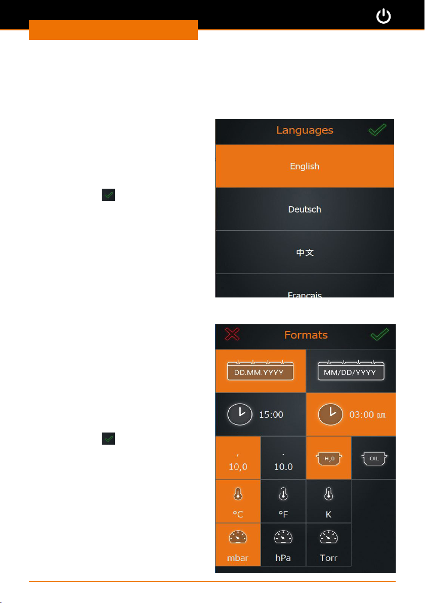
When the device is switched on for the rst time, you will be asked to make several basic
settings.
Setting the language
✓ A list of selectable languages is
displayed.
➜ Swipe down on the screen to see more
languages.
➜ Tap the desired language.
✓ The selected language is highlighted in
orange.
➜ Conrm with
✓ The window for setting the formats is
displayed.
Determine formats and units
➜ Tap the desired format or the desired
unit for:
▪ Date
▪ Clock
▪ Decimal numbers
▪ Heating bath uid
▪ Temperature
▪ Pressure
✓ The corresponding selection is
highlighted in orange.
➜ Conrm with
✓ The window for setting date and time is
displayed.
.
.
19
Page 20
Start-up
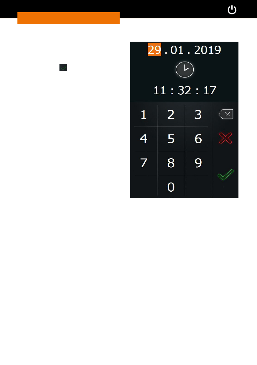
Setting date and time
➜ Tap the pair of digits for the date or the
time which you want to change.
➜ Tap the number pad to change the corre-
sponding setting highlighted in orange.
➜ Conrm with
.
20
Page 21
Start-up
Menu navigation
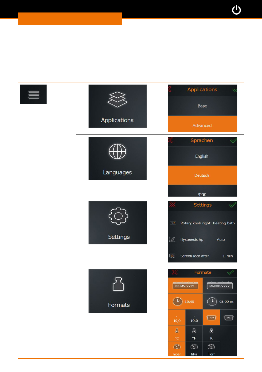
Overview of the menu tree
From the start page you can switch to the two menus “Basic Settings” and
“Operating Modes”)
Menu "Basic Settings"
21
Page 22
Start-up
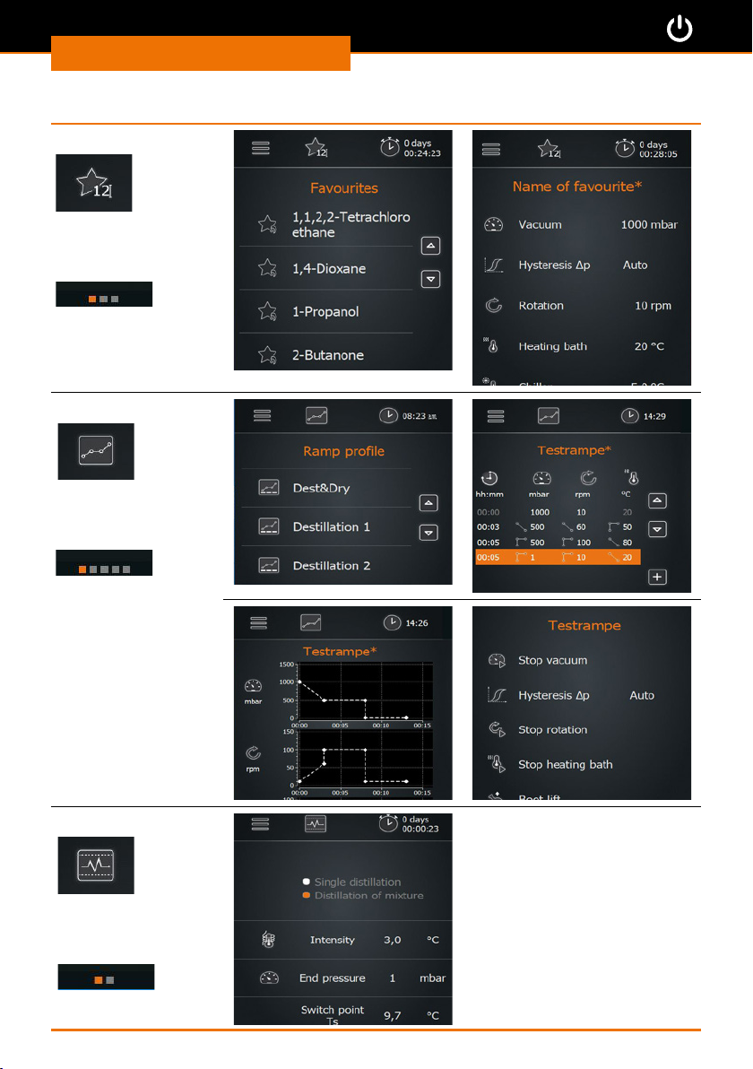
Menu “Operating Modes” (only visible in “Applications extended”):
Favorites mode
3 menu pages
Ramp mode
5 menu pages
AUTOaccurate mode
2 menu pages
22
Page 23
Start-up
Operation of the menu
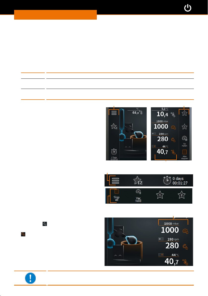
All numbers and symbols are touch-sensitive with the exception of the temperature
display for the condenser.
▪ The symbols of the menu bars direct you to more submenus or activate processes.
▪ The numbers on the right edge of the display show the selectable process parameters
which can be activated and changed by tapping.
▪ Active elements are highlighted in color in the schematic drawing of the device. The
colors are dened as follows:
White indication
Orange ▪ either: function activated
Grey the indicated function is deactivated
Hei-VAP Expert and Hei-VAP Ultimate have
the same menu navigation. In essence,
only the arrangement of the control
elements is dierent:
Hei-VAP Expert
The menu bars are located on the left and
right edge of the control panel.
▪ or: setpoint has just been changed via the rotary knob
(cannot be used at the moment, e.g. because accessory is not attached)
Menu bar left Menu bar right
Hei-VAP Ultimate
The menu bars are located on the top and
bottom edge of the control panel.
Toolbar: Symbols
➜ In the toolbar, tap a symbol (such as
“Rotation”
✓ The symbol changes its color to orange
✓ The function starts.
).
The display varies depending on the chosen operating mode, the
selected application and the attached peripheral equipment.
Toolbar
Menu bar top (example)
Menu bar bottom (example)
Toolbar
23
Page 24
Start-up
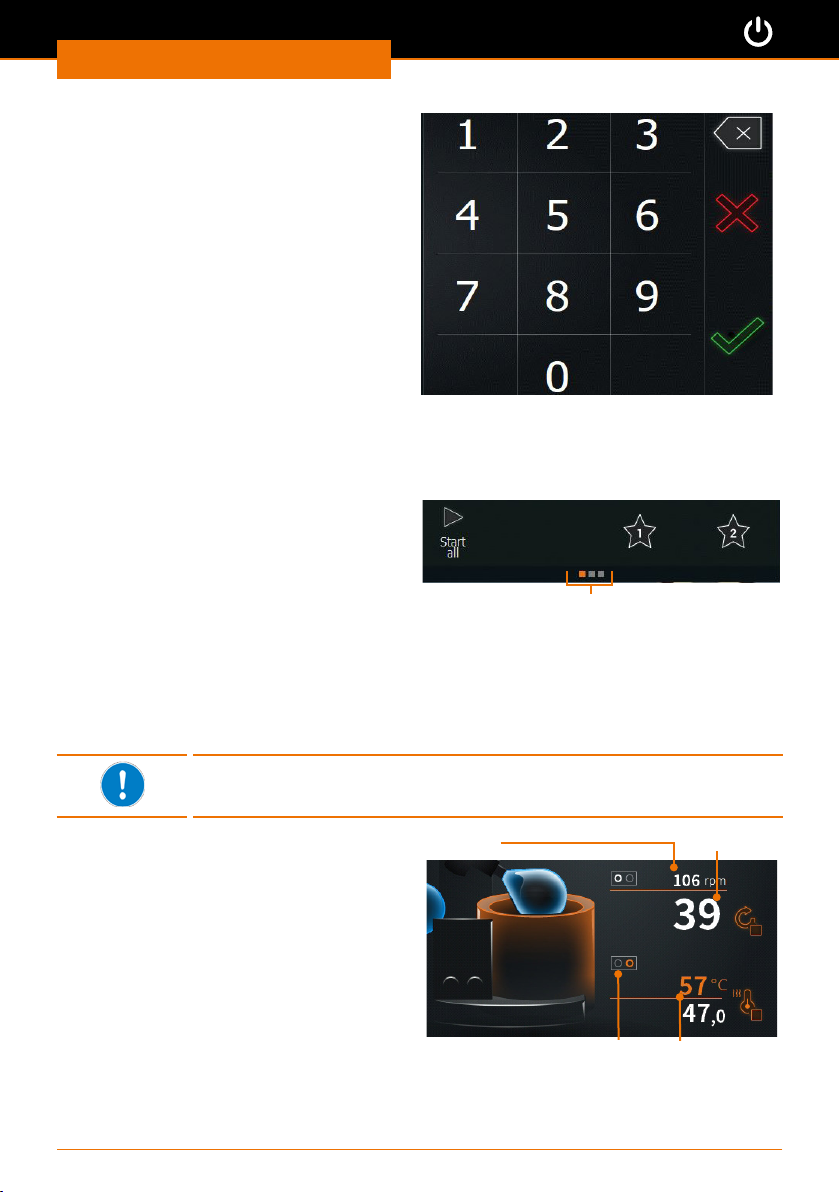
Toolbar: Numbers
➜ Tap the number of a setpoint.
➜ The adjacent numbers menu is
displayed.
➜ Tap the respective number to enter the
desired parameter value.
✓ If you enter an invalid value, the valid
range of values is indicated for a short
time.
➜ Tap the green checkmark to conrm
your entry.
➜ Tap the red cross to cancel your entry.
Open submenus
➜ Swipe the control panel from left to right (or the other way round) to switch to the
next screen.
In all three operating modes, small squares
appear at the bottom edge of the screen,
the quantity of which indicates the page
number of the submenus.
Information on submenus (example)
Additionally active elements are highlighted in color in the schematic drawing of the
device. For example, if the heating is switched on, the heating bath is lit orange.
If a vacuum pump or a chiller of series Hei-CHILL is attached, their setpoints and actual
values are also displayed on the start page with the symbol for switching on and o. The
setpoint can be changed by tapping on the corresponding number.
The values for rotation, temperature and vacuum can be adjusted
both by means of the touch-sensitive control panel or by means of the
rotary knob (see subsequent page).
Setpoints on the start page:
The setpoints are displayed in small print
above the line. The actual values are
displayed in large print below the line.
When adjusting a setpoint with the rotary
knobs, this value is displayed in larger print
and in orange for a short time.
Setpoint
Current assignment of
the rotary knob
24
Actual value
Setpoint during
entry
Page 25
Start-up
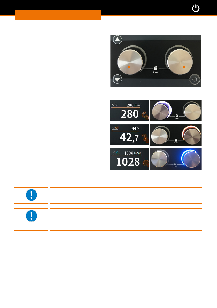
Adjustments via the rotary knobs:
➜ Turn the rotary knob to adjust the
desired value.
➜ Press the rotary knob to activate the
function.
Use the right rotary knob to adjust either
the temperature or the vacuum.
* The assignment of the right rotary
knob can be changed in the settings
(see chapter “Start-up, Basic settings”,
section “Setting the process sequence
parameters”).
✓ When rotation is switched on, the left
rotary knob lights up with a white illuminated ring.
✓ If the right rotary knob is assigned to
“temperature”, the rotary knob lights up
with an orange illuminated ring when the
heating is on.
✓ If the right rotary knob is assigned to
“vacuum”, the rotary knob lights up with
a blue illuminated ring when the vacuum
is on.
Rotation knob Temperature/vacuum
rotary knob*
✓ Press the rotary knobs again to switch o the heating resp. the vacuum or the
rotation.
You can protect the adjusted setpoints (rotation speed and temperature/vacuum) against unintentional adjustment by keeping the
appropriate rotary knob pressed for approx. 2 sec.
You determine the increment by means of the rotation speed.
You can adjust the desired value precisely or quickly by turning the
rotary knob slowly (increment of 1), medium-fast (increments of 25)
and quickly (increments of 50).
25
Page 26
Start-up
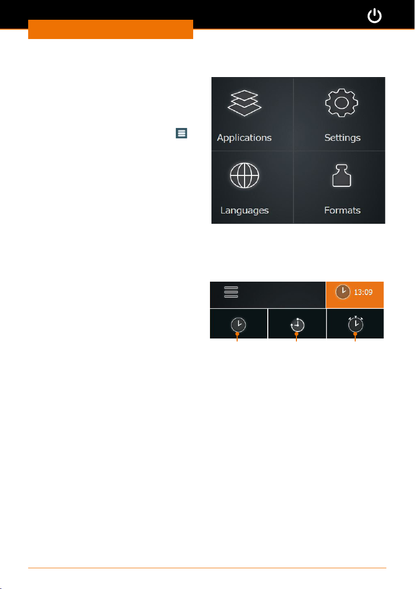
Changing the basic settings
Language and formats
You can change the language and the
formats in the main menu “Basic settings”
at any time.
➜ Tap the symbol for basic settings
the start page.
➜ In the menu “Basic settings”, tap
“Languages”.
✓ An overview of the selectable languages
is shown.
➜ In the menu “Basic settings”, tap
“Formats”.
✓ An overview of the selectable formats is
shown.
on
Date and time
Three dierent time symbols can be displayed in the menu bar of the start page.
➜ Tap the displayed time symbol.
✓ Three dierent time symbols are shown.
➜ Tap to select the clock symbol.
➜ Keep the clock symbol pressed for
approx. 3 sec.
✓ The window for setting date and time is
displayed.
Clock Timer Stopwatch
26
Page 27
Start-up
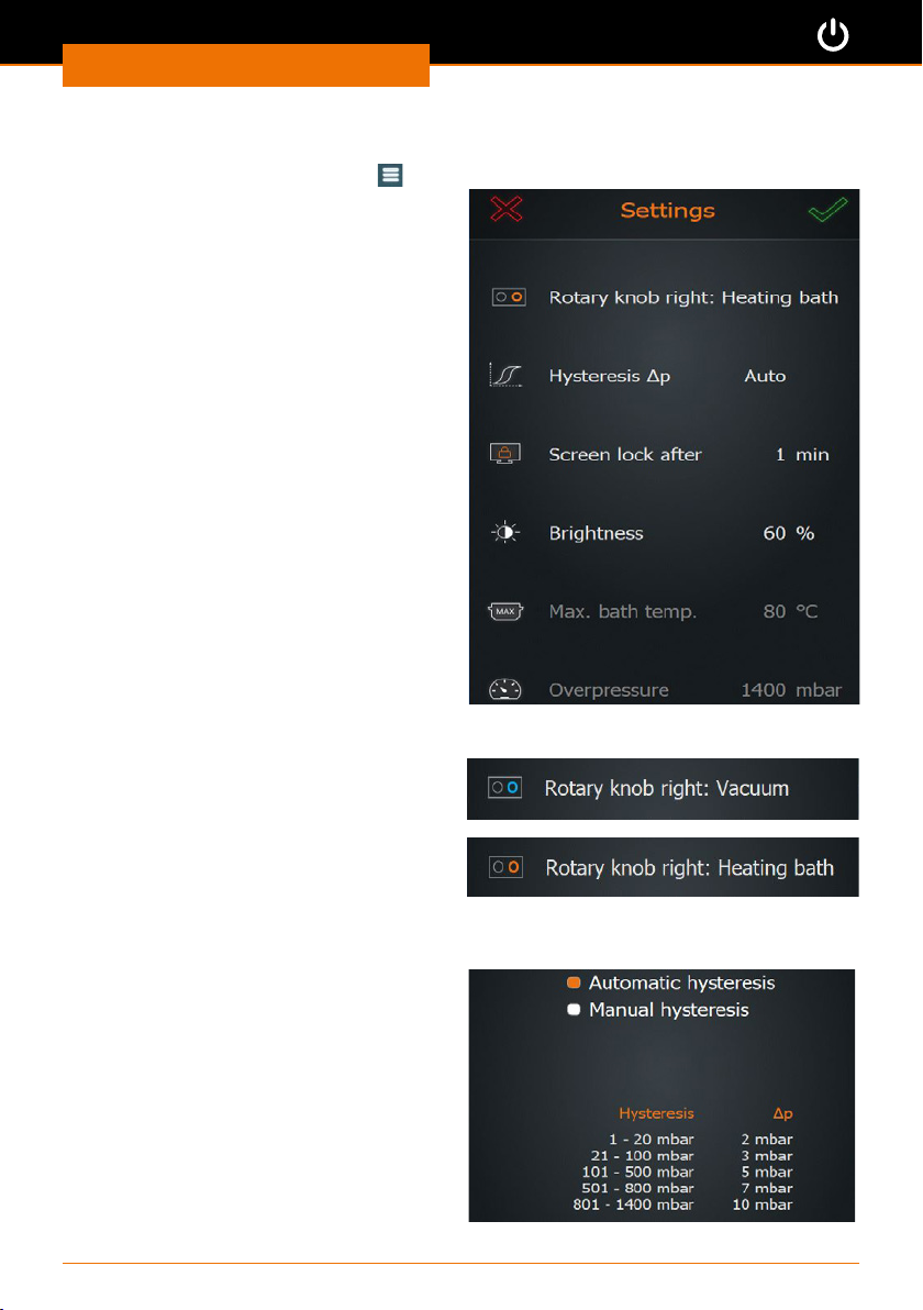
Settings
➜ Tap the symbol “Basic settings” on the start page.
➜ In the menu “Basic settings”, tap
“Settings”.
✓ A list of congurable settings is
displayed.
➜ Swipe down to see more settings.
✓ The following settings can be made:
▪ Rotary knob assignment
▪ Pressure hysteresis
▪ Period to screen lock
▪ Brightness of display
▪ Maximum bath temperature
▪ Excess pressure
▪ Leakage pressure
▪ Max. pump capacity
▪ Pressure sensor calibration
▪ Lift activation
▪ Factory settings
1. Assignment of the right rotary knob
It is possible to assign two dierent
functions to the right rotary knob. You can
choose if you want to use it to regulate
either the temperature or the pressure
(vacuum).
➜ Tap the menu item to change the rotary
knob assignment.
2. Pressure hysteresis
You can set by how many millibar the
pressure is allowed to rise before the
vacuum valve opens again.
➜ Tap “Hysteresis ∆p”.
➜ Choose between automatic and manual
hysteresis.
“Automatic hysteresis” contains prede-
ned hysteresis values for several pressure
ranges.
In “Manual hysteresis”, you can enter a
value between 1 and 50 mbar which applies
uniformly over the whole vacuum pressure
range.
27
Page 28
Start-up
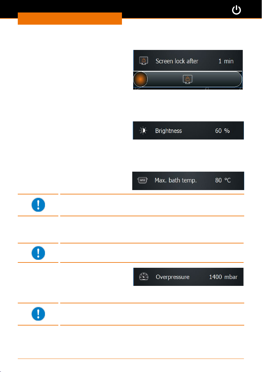
3. Screen lock
The screen lock can be set to last between 1 to 60 min.
➜ Tap “Lock screen” and set the desired
time.
➜ To unlock, tap the control panel.
➜ Swipe the orange ball from left to right
to unlock.
✓ The screen is unlocked.
4. Brightness of display
The brightness of the screen can be adjusted from 10% to 100%.
➜ Tap “Brightness” and adjust the desired
percentage value in increments of 10.
5. Maximum bath temperature
In order to protect, for example, sensitive samples, you can set a maximum temperature
here. It will then not be possible to manually enter values above this temperature.
➜ Tap “Max. bath temp.” and set the
desired maximum temperature (max.
90°C for water and max. 210°C for oil).
When loading favorites and ramp proles, the system checks if the
set maximum bath temperature could inuence the process and will
display a message, if needed.
6. Excess pressure
Here you specify the vacuum pressure at which the device will automatically cancel a
running process for safety reasons.
Default factory settings: 1400 mbar
Range of maximum values: 900 mbar - 1400 mbar
➜ Tap “Excess pressure” and set the
desired maximum pressure for vacuum.
✓ Once the set pressure is reached, vacuum, rotation and heating are stopped, the ask
lift is moved up, and a corresponding warning message appears.
When loading favorites and ramp proles, the system checks if the set
maximum pressure will inuence the process, and displays a message,
if needed.
28
Page 29
Start-up
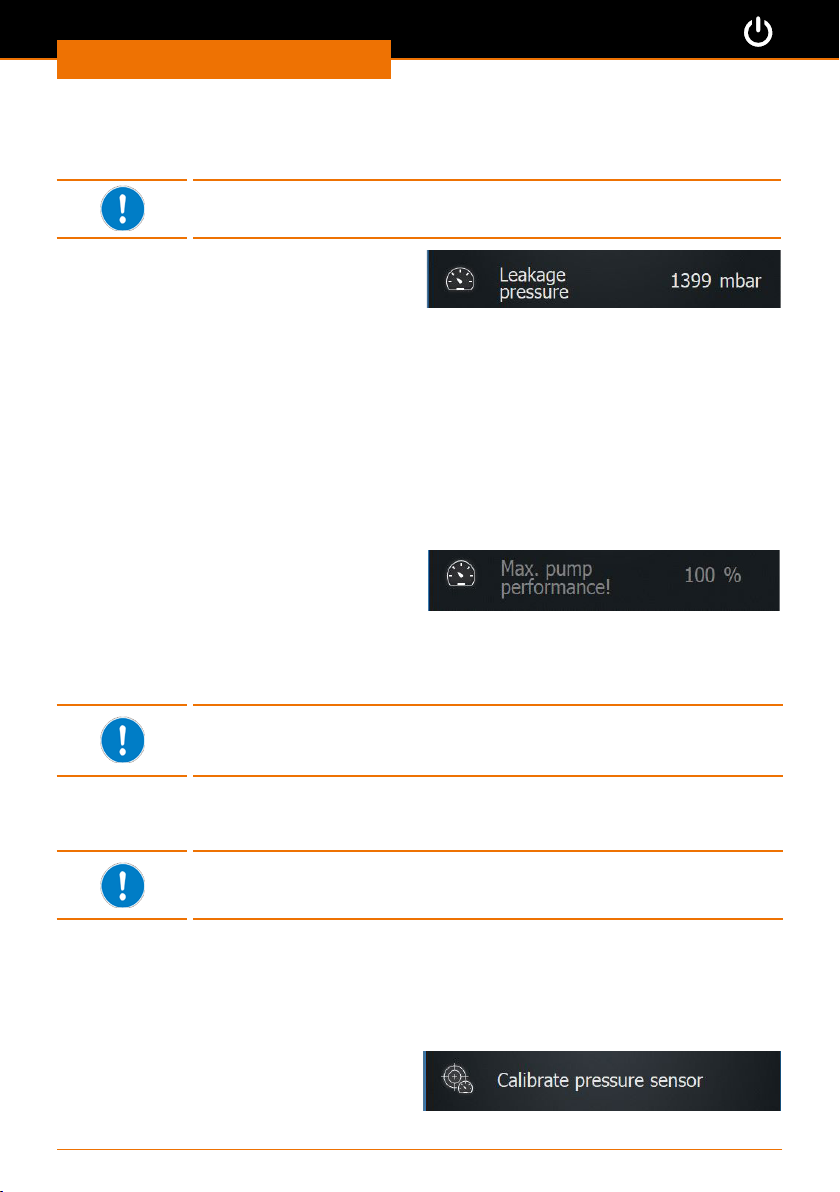
7. Leakage pressure
Here, you dene at which leakage pressure the device will automatically cancel a running
process for safety reasons.
Default factory settings: 1399 mbar
Range of maximum values: 1 mbar - 1399 mbar
➜ Tap “Leakage pressure” and set the
desired maximum leakage pressure.
✓ Once the pressure during pumping out falls below the leakage pressure, the safety
function is activated.
✓ If the value is exceeded during pumping out - for example because of glass breakage
or leakages - vacuum, rotation and heating are stopped, the ask lift is moved up,
and a corresponding warning message appears.
8. Max. pump capacity
A reduction in the suction capacity leads to a higher recovery rate of the solvent.
When using a speed-controlled pump (Rotavac Vario control and Rotavac Vario tec), here
you can reduce the max. pump capacity down to 20% by increments of 10% in order to
prevent foaming or delay in boiling.
➜ Tap “Max. pump capacity” and set the
desired capacity in percent.
If a valve-controlled pump is connected, the inscription is grayed out and it is not
possible to adjust the pump capacity.
9. Calibrating the pressure sensor
For calibration, we recommend to switch on the rotation in order to
ensure seal integrity of the system. If other processes are running
apart from the rotation, all processes will be stopped for calibration.
When using the vacuum sensor, you can calibrate it. For this purpose, you need an
calibrated external pressure gauge.
The basic calibration of the sensor is done by Heidolph Instruments.
Normally, a recalibration is not required.
✓ The vacuum sensor is attached and connected.
✓ The system is completely ventilated (no vacuum!).
✓ During calibration, a calibrated external pressure gauge is attached to the evaporator
system.
➜ Measure the atmospheric pressure on the calibrated external pressure gauge.
➜ Tap “Calibrate pressure sensor”.
➜ Following the instructions of the infor-
mation texts on the display:
29
Page 30
Start-up
➜ Enter the atmospheric pressure determined with the external pressure gauge.
➜ Close all openings on the evaporator system.
✓ When the atmospheric pressure has been entered and conrmed, the vacuum control
will start automatically. When the system has been evacuated to a low value and
keeps it stable, the second calibration value can be entered.
➜ Wait until the attached vacuum pump cannot reduce the pressure any further and
consequently the lowest possible vacuum pressure has been reached. Enter this
value.
➜ Conrm this value.
The calibration has now been corrected on the basis of the entered values.
If calibration is cancelled, the entered values are discarded. If you restore the factory
settings, the entered calibration values are also discarded and replaced by the default
values.
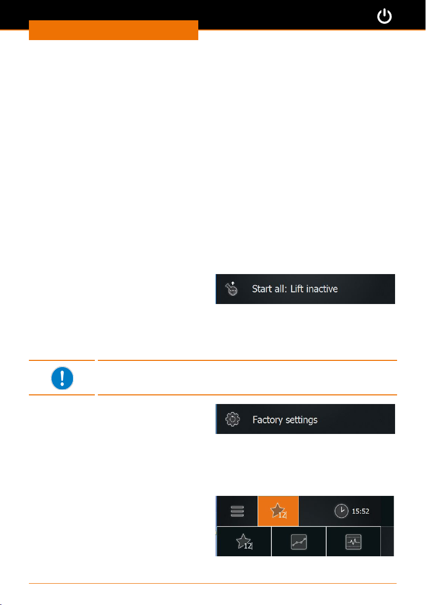
10. Lift activation
For motor lift devices, you can set that the ask is automatically lowered into the heating
bath upon starting the processes. The lift will move completely downwards. If you use
a foaming inhibitor or a dierent individual arrangement with a bigger glass ask, you
can also suppress the automatic downward movement of the lift at the start to prevent
potential glass breakage.
➜ Tap “Start all: Lift deactivated” /“Start all:
Lift activated”.
✓ If you have selected “Start all: Lift deacti-
vated”, you have to immerse the ask by
means of the lift buttons.
11. Factory settings
You can restore the factory settings at any time.
When you tap “Factory settings” and conrm the security prompt, your
favorites and ramp proles are deleted!
➜ Tap “Factory settings”.
✓ The factory settings or the settings of the
last update are restored.
Applications
Changing the operating mode
➜ In the menu bar, tap the symbol for the
current operating mode (example).
➜ The adjacent options menu is displayed.
➜ Tap the symbol to switch to the appro-
priate operating mode.
30
Page 31
Start-up
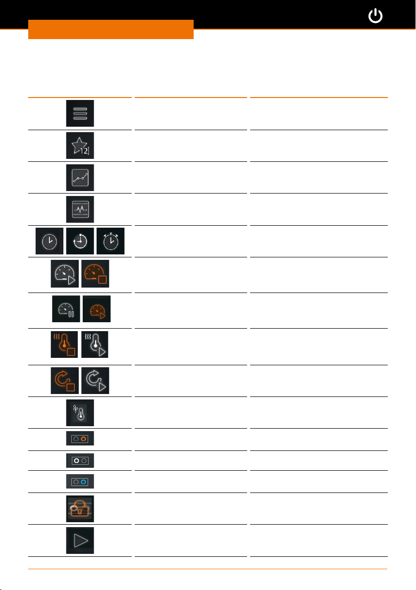
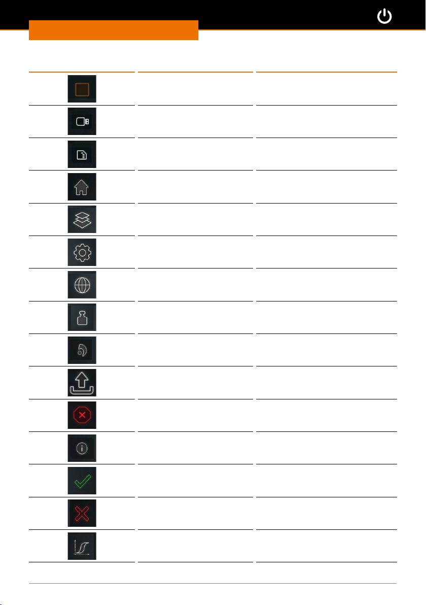
Symbols used
Symbol Designation Function or display
Menu Open the “Basic Settings” menu
Favorites mode Activate favorites mode
Ramp prole mode Activate ramp prole mode
Automatic mode DAA Activate automatic mode DAA
Clock/timer/stopwatch Display/measure/stop time
Vacuum o/on Start/stop vacuum control
Maintain/start vacuum Stop/restart vacuum control
Heating bath on/o Switch the heating on/o
Rotation on/o Start / stop rotation
Vapor temperature Monitor vapor temperature
Rotary knob right: Heating
bath
Rotary knob left: Vacuum Rotation switched on
Rotary knob right:
Vacuum
Rotary knob locked Rotary lock
Start all Start all processes
31
Heating bath switched on
Vacuum switched on
Page 32
Start-up
Symbol Designation Function or display
Stop all Stop all processes
USB port USB stick is available
SD port SD card is available
Start page Return to start page
Applications Select basic or extended
Settings Open settings
Language selection Open language selection
Format selection Open format selection
System check Display list of all connected
System update Update system
Error Open list of errors
Information Open software information
OK Conrm entry
Cancel Cancel process
Hysteresis Set hysteresis
32
components
Page 33
Start-up
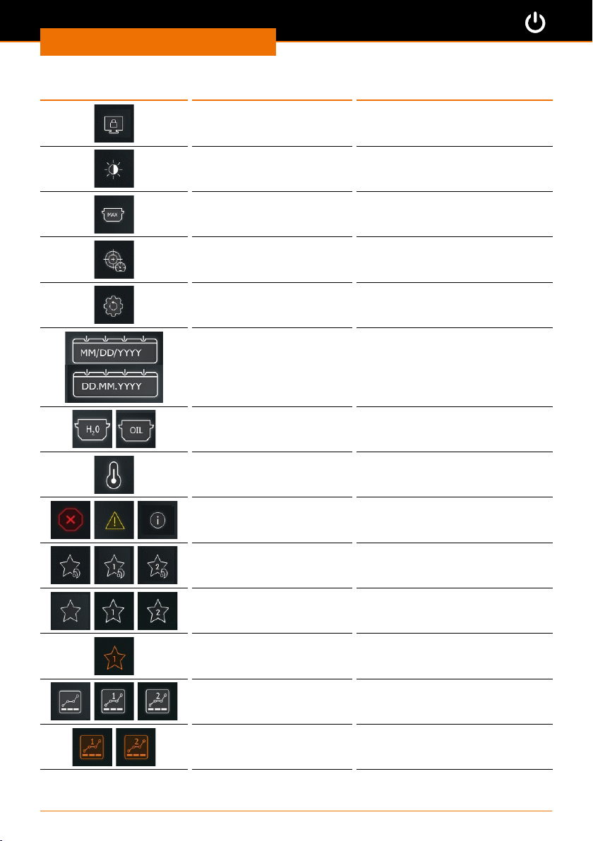
Symbol Designation Function or display
Lock screen Activate screen lock
Display brightness Adjust display brightness
Max. heating bath
temperature
Calibrated pressure Calibrate the pressure sensor
Factory settings Restore factory settings
Date format German/
English
Heating bath H2O, oil Select heating bath
Temperature units Select temperature units
Error/Warning/Information List of errors: Error/Warning/
Favorite Heidolph/Favorite
1 Heidolph/Favorite 2
Heidolph
Favorite/Favorite 1/
Favorite 2
Favorite 1 activated Loaded favorites
Indicate max. heating bath
temperature
Select date format
Information
Default favorites,
Favorite 1 and Favorite 2 are on
quick-selection buttons
Own favorites,
Favorite 1 and Favorite 2 are on
quick-selection buttons
Ramp prole/Ramp prole
1/Ramp prole 2
Ramp prole 1 activated Loaded ramp prole
33
Own ramp proles,
prole 1 and prole 2 are on
quick-selection button
Page 34
Start-up
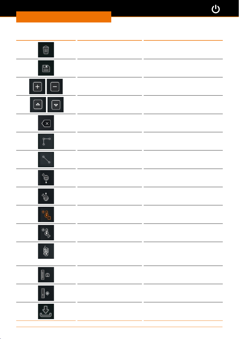
Symbol Designation Function or display
Delete Delete selection
Save Save selection
Add/remove line Add/remove ramp prole line
Line or page up/down Move or scroll ramp prole line
Backspace Delete character
up/down
Stepwise ramp Ramp prole: Value adjustment
Linear ramp Ramp prole: Continuous value
Move lift down Ramp prole settings: Stop lift
Raise lift Ramp prole settings: Move lift
Chiller on Ramp prole setting; maintain
Chiller o Ramp prole settings; stop
Temperature display Current value indication of the
Vacuum module Plug-in card present in control
Chiller module Plug-in card present in control
in steps
adjustment
up
cooling
chiller
external temperature sensor
(vapor temperature sensor or
AUTOaccurate sensor)
box
box
List on USB Export list of favorites or ramp
34
proles to USB stick
Page 35
Operation
Operation
Process sequence
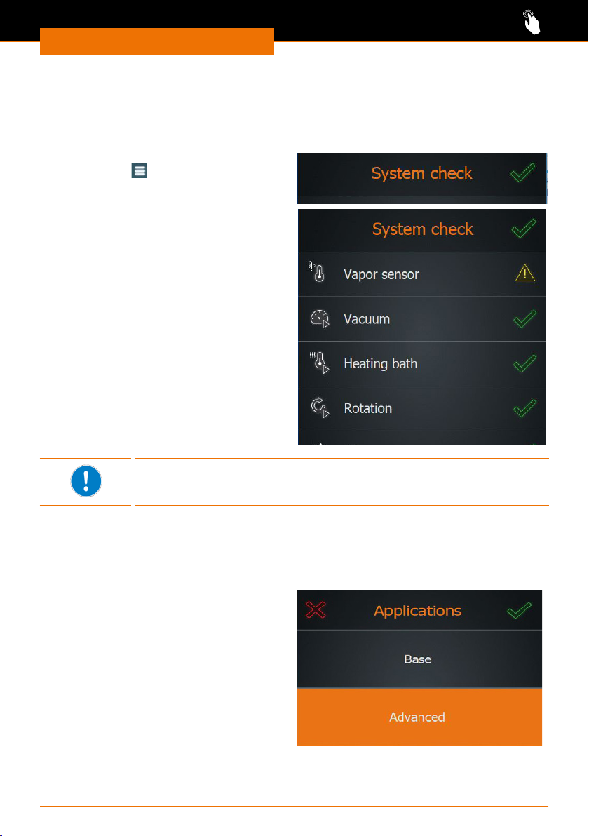
Performing a system check
After switching on the device, you can check in the overview list if all components are
connected.
➜ Open the menu “Basic settings” with
the symbol
➜ In the menu “Basic settings”, tap the
symbol “System check” at bottom left.
✓ The list of attached components is
displayed:
▪ rst, components which are not
attached (tagged with a yellow
triangle)
▪ followed by the attached
components (tagged with a green
checkmark).
If an attached component is not indicated:
➜ check the connections and restart the
device.
.
If peripheral devices, such as chillers and vacuum pump, are not
attached, the corresponding indications are grayed out in all menu
windows. Consequently, it is not possible to adjust their parameters.
Selecting an application
Depending on the desired process sequence, you can choose between two dierent applications:
▪ Basic: Here, you manually adjust the
basic parameters (vacuum, rotation
and temperature) before starting the
evaporation.
▪ Extended: Here, you can create and
use individual favorites or ramp proles
or select the automatic process control.
➜ Tap “Applications” in the menu “Basic
settings”.
➜ Select the desired application and
conrm with the green checkmark.
When you have selected the application “Extended”, you can choose one of the following
modes:
35
Page 36
Operation
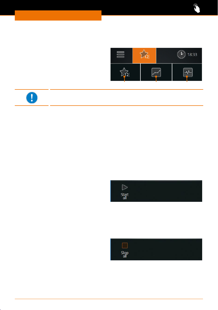
▪ Favorites mode (selected as a standard)
▪ Ramp prole mode
▪ Automatic mode DAA
➜ In the menu bar, tap the symbol of the
operating mode used last.
✓ The symbols of the three operating
modes are displayed.
➜ Tap the symbol of the desired operating
mode.
RampsFavorites DAA
To switch applications, the current processes have to be stopped.
Detailed descriptions are found in the following chapters:
▪ “Grundparameter manuell einstellen („Basis”)” on page 32
▪ “Favoriten verwenden und verwalten („Erweitert”)” on page 36
▪ “” on page 39
▪ “Automatikmodus DAA verwenden („Erweitert”)” on page 45.
Any chiller attached can be operated in all applications and modes.
Starting / stopping all processes
It is not only possible to start individual functions but also to start all functions at once.
✓ The desired settings have been made, parameters, favorites or ramp proles have
been selected.
✓ Ensure that no glass breakage will occur.
➜ In the menu bar of the current appli-
cation, tap “Start all” (or “Start prole”,
“Start DAA”).
✓ The functions rotation, heating bath, pump (vacuum) and, if needed, stopwatch are
started.
✓ If a chiller is attached, it will not be started.
✓ The lift will move down all the way if it is activated in the settings.
✓ With “Start DAA”, the AUTOaccurate temperature is determined prior to starting the
processes.
➜ In the menu bar of the current appli-
cation, tap “Stop all” (or “Stop prole”,
“Stop DAA”).
✓ All started processes are stopped.
✓ The possibly attached chiller is not stopped.
✓ The stopwatch stops and the value is displayed until the stopwatch is restarted with
“Start all”.
36
Page 37
Operation
Recording process times
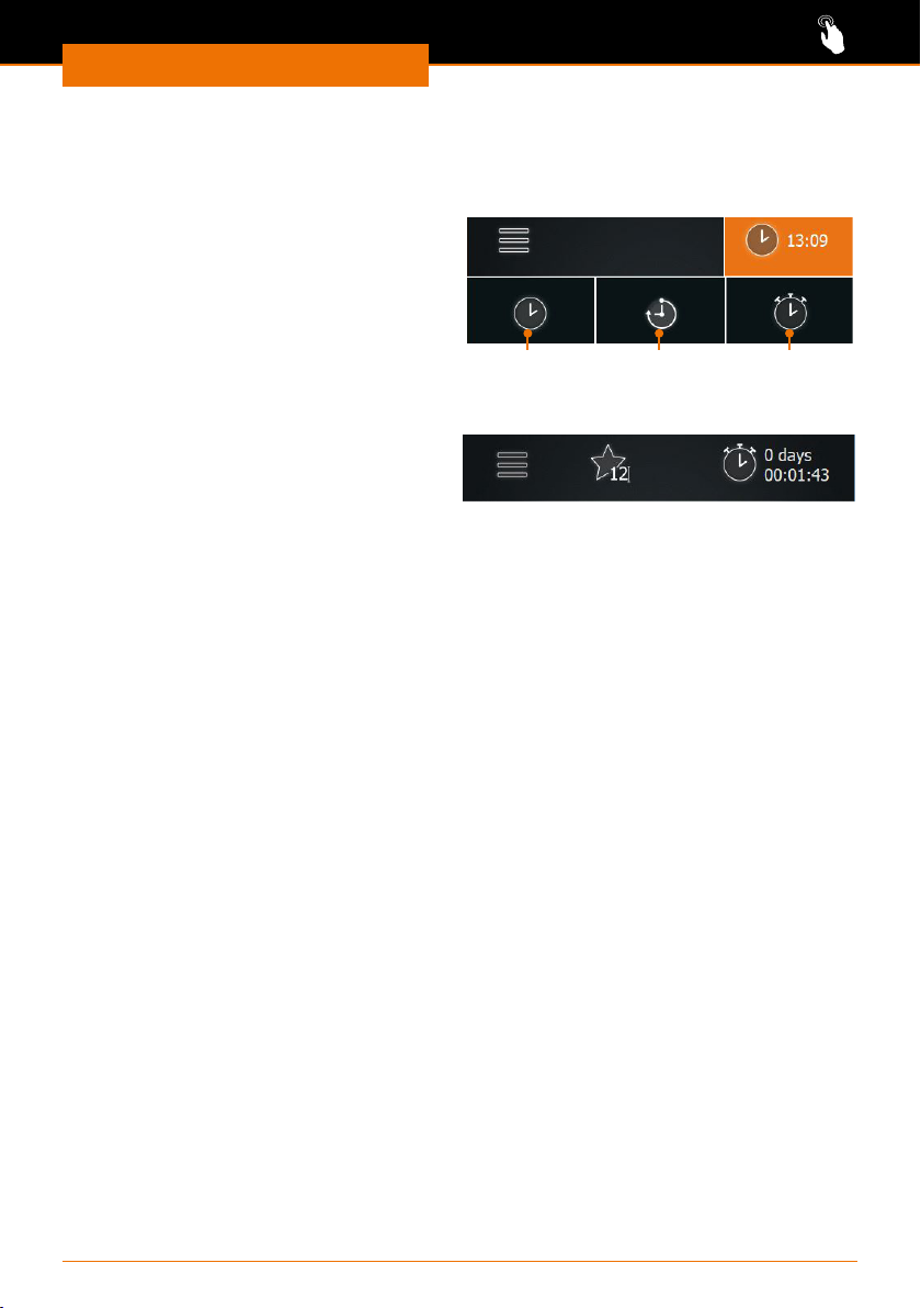
The stopwatch is automatically measuring the time of all processes which lets you keep
track of the times of any process and enables you to record them if needed.
➜ Start any desired process.
✓ The time display switches to the
stopwatch, and the stopwatch starts
running.
✓ Thus, you know at any time how long
the process has taken up until then.
➜ Stop the process.
✓ The time display switches to the clock.
➜ Switch the time display to “Stopwatch”.
✓ On the display, the elapsed time is still
shown next to the stopwatch symbol.
The stopwatch shows the duration of the last process until a new process begins or until
the device is switched o.
Clock Timer Stopwatch
37
Page 38
Operation
Applications
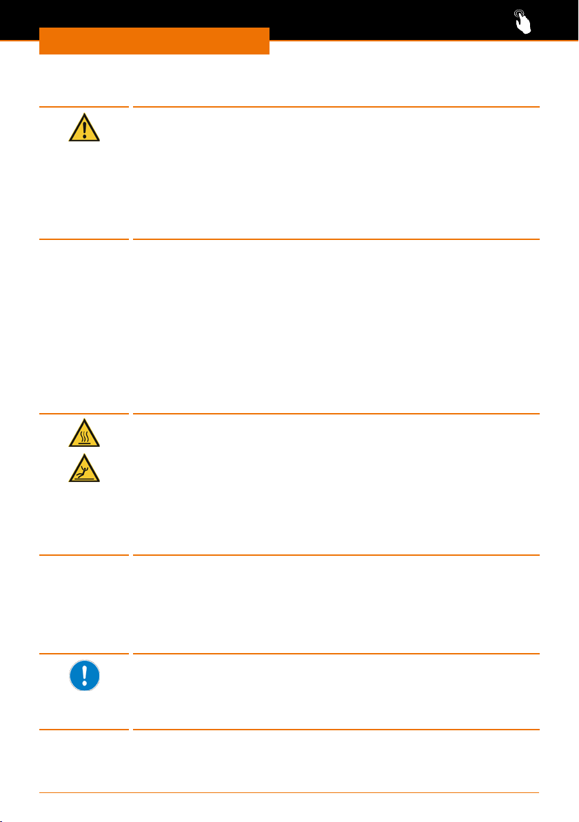
Warning:
Possible unintentional parameter changes
As long as the screen and the rotary knobs are activated, there is the
danger that parameters are changed unintentionally.
If the device is to operate unattended, do not go away before the
rotary knobs have been locked and the screen lock has been activated.
(See chapter “Operation, Setting parameters manually”, section “5.
Protecting setpoints” as well as chapter “Start-up, Settings”, section
“3. Locking the screen”.)
Setting parameters manually (“Application Basic”)
1. Setting the rotation speed
The distillation speed can be increased by increasing the rotation speed. The shortened
distillation time contributes to the thermal protection of the distillate.
However, depending on the size of the evaporating ask and the selected heating uid,
dierent rotation speeds are appropriate.
Rotation speed range and adjustment
The rotation speed can be set between 10 rpm and 280 rpm.
Warning:
Risk of scalding! Risk of slipping!
At high rotation speeds, the heating bath uid can splash and/or spill
over, resulting in slippery oors and severe scalding.
If you operate the device without a safety hood:
▪ Always test the uid used before a process and document the
spraying behavior!
▪ Make this documentation available to all employees.
▪ Wear protective clothing near the device.
▪ Make sure the oor is clean.
➜ Test the uid selected by you:
▪ at slowly increasing temperatures
▪ with your dierent evaporating ask sizes
▪ with increasing rotation speeds
➜ Note the results and make them available to all employees.
The viscosity and volume of the oil change depending on the oil
selected, the age of the oil and the setting of the bath temperature.
For this reason, document both the exact name/manufacturer speci-
cation and the period of use for oil and repeat the documentation at
specied time intervals.
✓ The base device is switched on.
✓ The evaporating ask is immersed in the heating bath.
38
Page 39
Operation
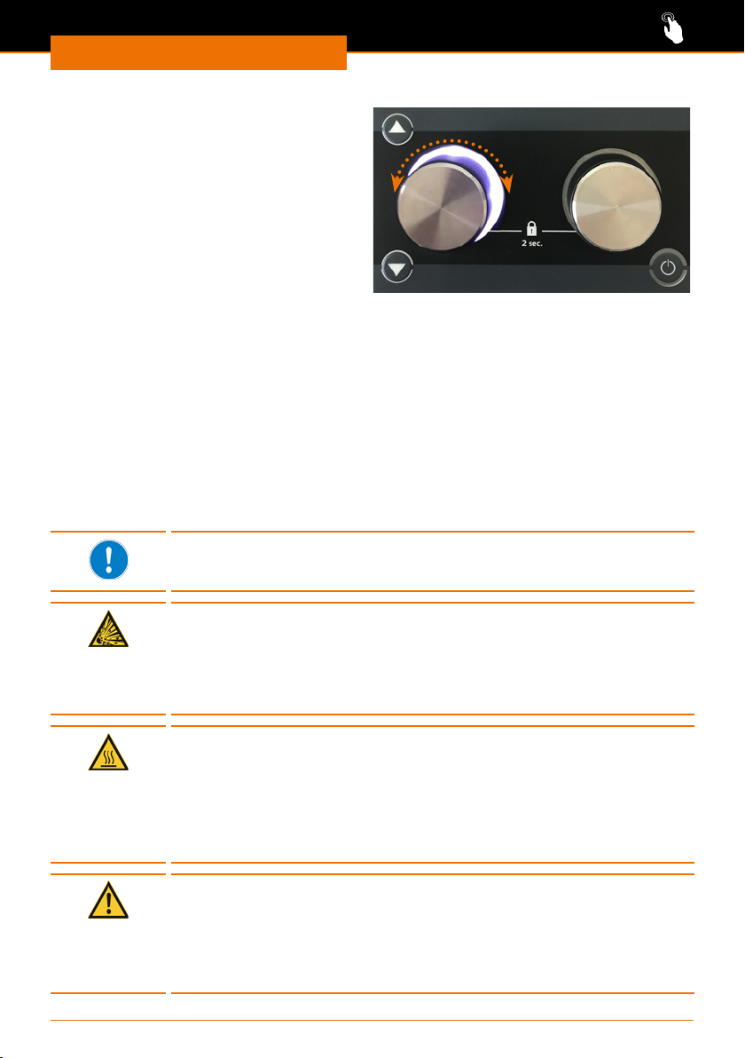
➜ Adjust the desired rotation speed via
the rotary knob.
Alternatively, you can also enter the
rotation speed setpoint on the control
panel:
➜ On the display, tap the indication
of the rotation speed and enter the
desired value.
➜ To start the rotation press the rotary
knob or tap the symbol “rotation” on
the display.
✓ The rotary knob and the symbol of the evaporating ask on the start page are lit
white as long as rotation is switched on.
➜ Switch o rotation by pressing the rotary knob again or by tapping the symbol on the
display again.
2. Setting the bath temperature
Temperature range available:
The temperature range can be set between 20 °C and 210 °C.
▪ Permissible temperature range when using water: 20 °C - 90 °C
▪ Permissible temperature range when using oil: 20 °C - 210 °C
Starting at a desired bath temperature of 75 °C, we recommend to
use polyethylene glycol or silicone oil as heating uid (see also chapter
“Spare Parts and Accessories, Accessories”).
Warning:
Risk of death! Risk of explosion!
If you use an unsuitable oil as heating bath uid, the oil can ignite and
possibly cause an explosion.
➜ Use only oil with a ash point > 285 °C.
Warning:
Risk of scalding!
If you operate your device without a safety hood, severe scalding may
occur at high bath temperatures.
Be sure to wear protective clothing (safety glasses, protective
clothing, safety gloves) when you are near the device while a process
is running.
Caution:
Possible device damage
The heater responds very quickly. If the heating bath is empty
and heating is switched on, the heating bath may develop dark
discolorations.
Only switch heating on when the heating bath is suciently lled.
39
Page 40
Operation
Adjusting the heating bath temperature on the display:
✓ The base device is switched on.
✓ The heating bath is lled with oil or water.
✓ The evaporating ask is immersed in the heating bath.
➜ On the display, tap the indication of the bath temperature and enter the desired
value.
Adjusting the heating bath temperature with the rotary knob:
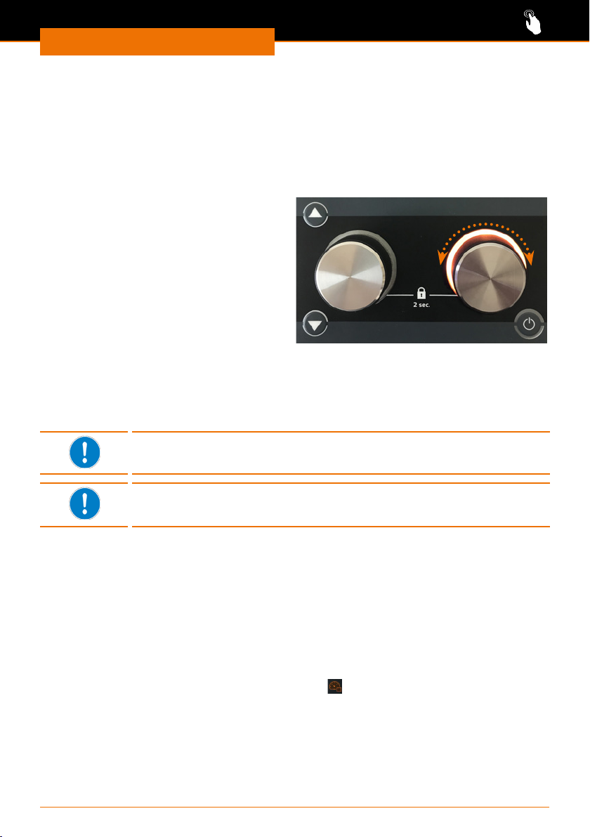
✓ The right rotary knob is assigned to
temperature adjustment.
➜ Set the desired temperature with the
right rotary knob.
➜ To start the heating, press the right
rotary knob or tap the “Heating bath”
symbol on the display.
✓ The right rotary knob and the heating
bath symbol in the control panel are lit
orange as long as heating is switched on.
➜ To switch o the heating, press the right rotary knob again or tap the “Heating bath”
symbol on the display.
✓ The orange illuminated ring ashes if there is still residual heat.
The frequency of ashing depends on the level of the current residual heat. The ashing
stops once the temperature drops below 50 °C.
If the vacuum setting is assigned to the right rotary knob, a message in
the control panel will indicate if the temperature due to residual heat is
above 50°C.
The display of the residual heat is only available when the device is
switched on and in standby mode. The residual heat is not displayed if
the device has been switched o via the main switch (ON/ OFF switch).
3. Setting the vacuum
Available pressure range:
The vacuum can be adjusted between 1 and 1400 [mbar], independent of the set safety
pressure. When switching on the vacuum control, a notice about the safety pressure is
displayed if needed.
✓ The base device is switched on.
Adjusting the vacuum on the display
➜ On the display, tap the pressure indication and enter the desired value.
➜ On the display, tap the “Start vacuum” symbol
✓ With valve-controlled pumps, the vacuum valve is switched on or o;
with speed-controlled pumps, the rotation speed is set to zero.
✓ The schematic drawing of the glass ask and the condenser are lit blue.
✓ If the vacuum setting is assigned to the right rotary knob, the ring will be lit blue.
➜ Tap the symbol on the display again to switch o the vacuum.
✓ The blue light will be extinguished.
40
.
Page 41
Operation
Setting the vacuum with the rotary
knob
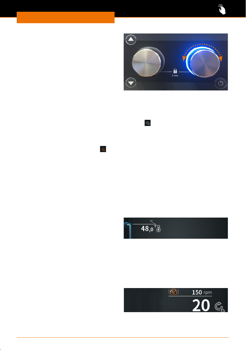
✓ The right rotary knob is assigned to the
vacuum setting.
➜ Set the desired pressure with the right
rotary knob.
➜ To start the vacuum, press the right
rotary knob or tap the symbol “Start
vacuum” on the display.
✓ The right rotary knob and the symbols of
the glass ask/condenser are lit blue.
Maintaining the vacuum
You can maintain the current vacuum at any time, for example, if the setpoint has not
been reached yet but you would like to stop the process for a short time.
➜ On the display, tap the “Maintain vacuum” symbol
(only available in favorites mode and in automatic mode DAA).
✓ The current actual value of the pressure is temporarily kept as setpoint.
✓ The symbol changes to the symbol for “Start vacuum”.
➜ Tap the “Start vacuum” symbol
level.
✓ Now, the system will continue to the congured setpoint.
to stop maintaining the vacuum at the paused
4. Display of vapor temperature / AUTOaccurate temperature
(optional accessory, see chapter “Spare Parts and Accessories”).
The vapor temperature is displayed in the control panel when the vapor temperature
sensor is attached.
The AUTOaccurate temperature is displayed, when the AUTOaccurate sensor is attached.
✓ The base device is switched on.
✓ You are in favorites mode or in ramp prole mode.
✓ When the vapor temperature sensor
is attached, the vapor temperature is
displayed at the top left of the control
panel, next to the condenser.
✓ You are in automatic mode DAA.
✓ When the AUTOaccurate sensor is attached, the AUTOaccurate temperature is
displayed at the top left of the control panel, next to the condenser.
5. Protecting setpoints
You can protect the setpoints for rotation speed and heating bath (or vacuum, depending
on the button assignment) from unintentional maladjustment.
➜ Press the respective rotary knob for
approx. 2 sec. to lock the setpoint.
✓ The locked value is signied by a lock.
➜ Press the rotary knob again for approx. 2 sec. to unlock the setpoint.
41
Page 42
Operation
Using and managing favorites (Application
“Extended”)
All parameters for the distillation of a substance are stored in a favorite with a xed
value. In this way, saving favorites allows quick access to dierent processes for your
various samples.
A favorite is suited for distilling solvents and for concentrating or purifying substances.
Since the parameters are stored with a single value, the favorite has to be switched o
manually at the end of the process or be stopped using the timer.
You access the favorites mode in the application “Extended”. In the favorites mode, you
can:
▪ load favorites from a list
▪ generate new favorites
▪ open a favorite directly by means of two quick-selection buttons
1. Loading favorites from a list
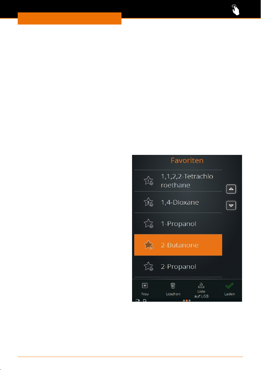
The factory settings already include various
favorites for solvents. They are marked
with a little Heidolph logo at the bottom
right of the favorites symbol.
✓ You are in the favorites mode in the
application “Extended”.
➜ Swipe the screen from right to left to
switch to the list of favorites.
➜ Tap the desired solvent.
✓ The solvent is highlighted in orange.
➜ Tap the “Load” symbol.
➜ The start page with the selected
favorites is displayed, and the process
can be started with the default
parameters.
It is also possible to delete and modify the Heidolph favorites. Once you have changed
and saved their parameters, the favorite is stored without a Heidolph logo on the symbol.
42
Page 43
Operation
2. Generating new favorites
You can add as many of your own favorites as you want to the existing favorites list.
✓ You are in the favorites mode in the application “Extended”.
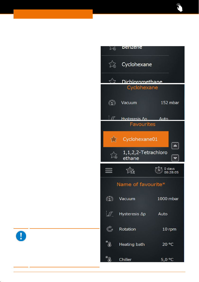
➜ Swipe the screen from right to left to
switch to the list of favorites.
Creating a favorite based on an existing
favorite
➜ Tap a solvent.
➜ Swipe the screen from right to left.
✓ The parameters for pressure, hysteresis,
rotation and temperature are displayed.
➜ Tap the elds of the parameters you want
to adapt and enter the values on the
number pad.
➜ Tap the “Save” symbol.
➜ Enter a new name and conrm with the
green checkmark.
✓ The new favorite is saved and will be
inserted at the top of the favorites list.
✓ The Heidolph logo is removed from the
favorites symbol.
✓ The original favorite still exists in the
Heidolph list.
Creating new favorites
➜ Tap the “New” symbol.
✓ Parameter suggestions are displayed
for pressure, hysteresis, rotation and
temperature.
➜ Tap the elds of the parameters which
you want to adapt and enter the values
on the number pad.
➜ Tap the “Save” symbol.
➜ Enter a new name and conrm with the
green checkmark.
✓ The new favorite is saved and added to
the favorites list.
If no chiller of the Hei-CHILL
series (Hei-CHILL 250-1200)
or a vacuum valve or a speedcontrolled vacuum pump by
Heidolph Instruments is attached,
the appropriate parameter is
grayed out. You can still enter and
save a value for them.
43
Page 44
Operation
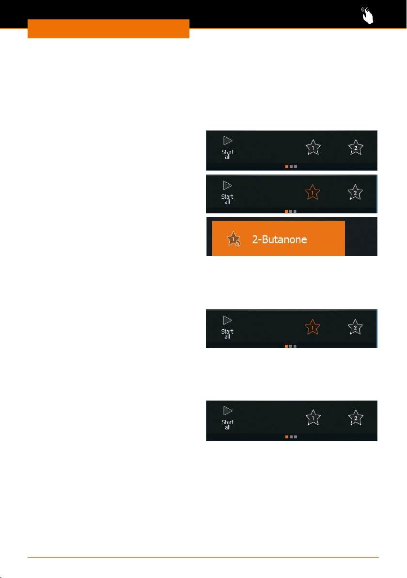
3. Assigning the quick-selection buttons
You can assign two favorites to the quick-selection buttons (asterisk symbol) on the start
screen. This enables you to load these favorites directly.
Re-assigning the quick-selection buttons
✓ You are in the favorites mode in the application “Extended”.
✓ The quick-selection buttons are not yet assigned to a favorite.
➜ Tap the symbol for quick-selection 1 or 2.
✓ The favorites list is displayed.
➜ Select a favorite and conrm with “Load”.
➜ Keep the desired quick-selection button
pressed for approx. 3 sec.
✓ The selected favorite is stored on the
quick-selection button.
✓ The favorite in the list of favorites is
tagged with the button assignment.
Changing the assignment of the quick-selection button
✓ One of the quick-selection buttons is assigned to a favorite.
➜ Swipe the screen from right to left to switch to the list of favorites.
➜ Load the desired favorite.
➜ Keep the quick-selection button pressed
for approx.
3 sec. to store the new favorite.
Loading a favorite with the quick-selection button
✓ You are in the favorites mode in the application “Extended”.
✓ You have assigned favorites 1 and 2.
➜ Tap the 1 or 2 symbol.
➜ The symbol turns orange, the selected
favorite is loaded, and you can start the
process immediately.
▪ If no favorite is currently loaded, you can jump to page 3 by keeping the symbol
pressed for some time in order to save the current parameters. In doing so, the
favorite is not stored on the quick-selection button.
▪ If a favorite is already loaded, you can save the current parameters by keeping the
selected quick-selection button pressed for some time.
44
Page 45
Operation
4. Deleting a favorite
✓ You are in the favorites mode in the application “Extended”.
➜ Swipe from right to left to switch to the list of favorites.
➜ Mark the favorite you want to delete.
➜ Tap the “Delete” symbol and conrm
the following prompt with the green
checkmark.
✓ The favorite is removed from the list.
5. Exporting the favorites list
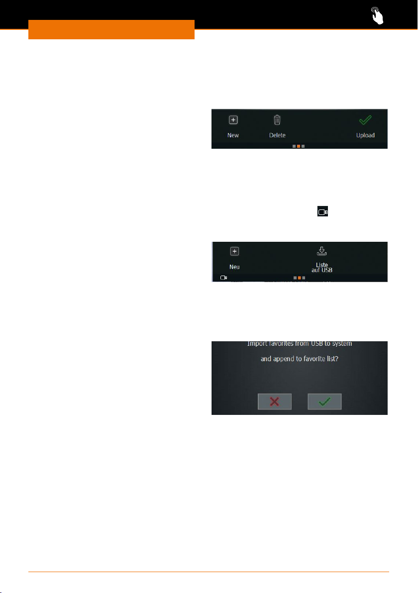
It is possible to save all favorites on a USB stick.
✓ You are in the favorites mode in the application “Extended”.
✓ The USB stick is inserted in the USB port, and the USB stick symbol
bottom edge of the screen.
➜ Swipe the screen from right to left to switch to the list of favorites.
➜ Tap the “List to USB” symbol and conrm
the prompt with the green checkmark.
✓ The list is saved.
6. Importing the favorites list
If you have saved a favorites list on a USB stick, you can import the list.
✓ You are in the favorites mode in the application “Extended”.
➜ Insert the USB stick with the favorites list
into the USB port.
✓ A message pops up asking if you want to
import the favorites list.
➜ Conrm the prompt.
✓ The favorites are imported.
appears at the
45
Page 46
Operation
Using and managing ramp proles (Application
“Extended”)
A ramp prole consists of a sequence of several individual process steps.
Just like saving favorites, the saving of ramp prole allows fast access to suitable process
sequences for your various samples.
A ramp prole is suited for the distillation of mixtures. At the end of a process, it is
possible to determine for each parameter individually if it is to be maintained or stopped.
You access the ramp prole mode in the application “Extended”. In the ramp prole mode
you can:
▪ generate new ramp proles
▪ open an existing ramp prole directly by means of two quick-selection buttons
Warning:
Risk of injury near the device!
When operating with ramp proles, the rotation speed, the heating
bath temperature and, if needed, the lift position are automatically
changed.
Maintain a safe distance from all parts of the device when it is
switched on and especially when a ramp prole is in operation.
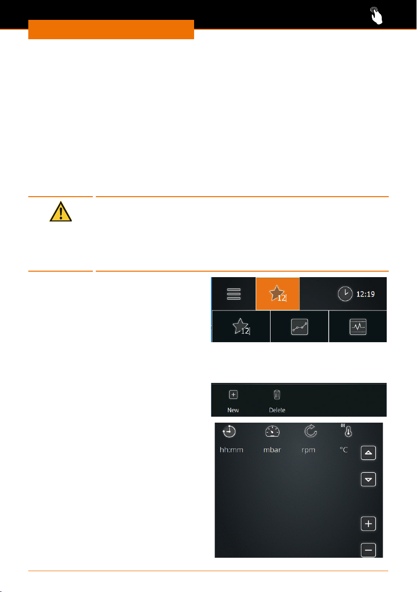
➜ In order to start the ramp prole mode,
tap the symbol in the menu bar depicting
the operating mode that was used last.
✓ The symbols of the three modes are
displayed.
➜ Tap the “ramp prole mode” symbol.
1. Generating ramp proles
✓ You are in the ramp prole mode of the application “Extended”.
➜ Swipe the screen from right to left to
switch to the list of ramp proles.
➜ Tap the “New” symbol.
✓ You switch to the ramp prole view.
46
Page 47
Operation
Generating and adding lines
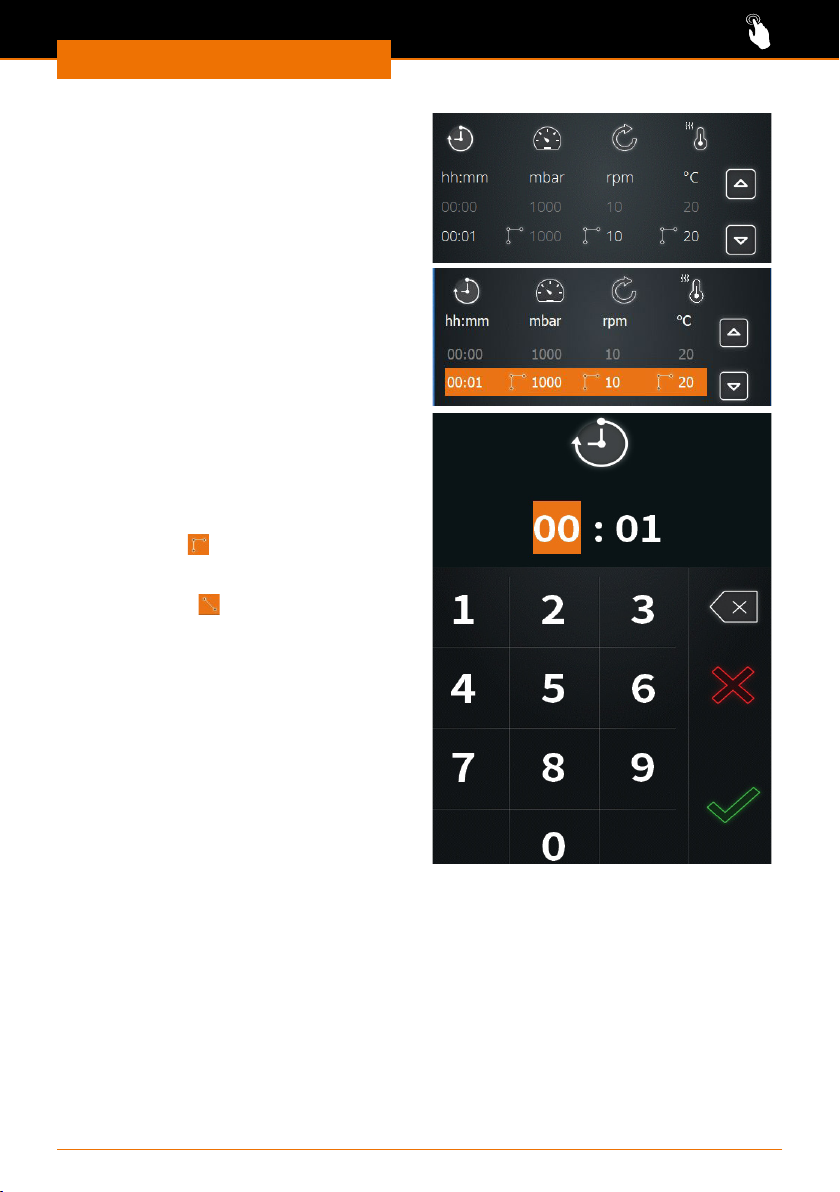
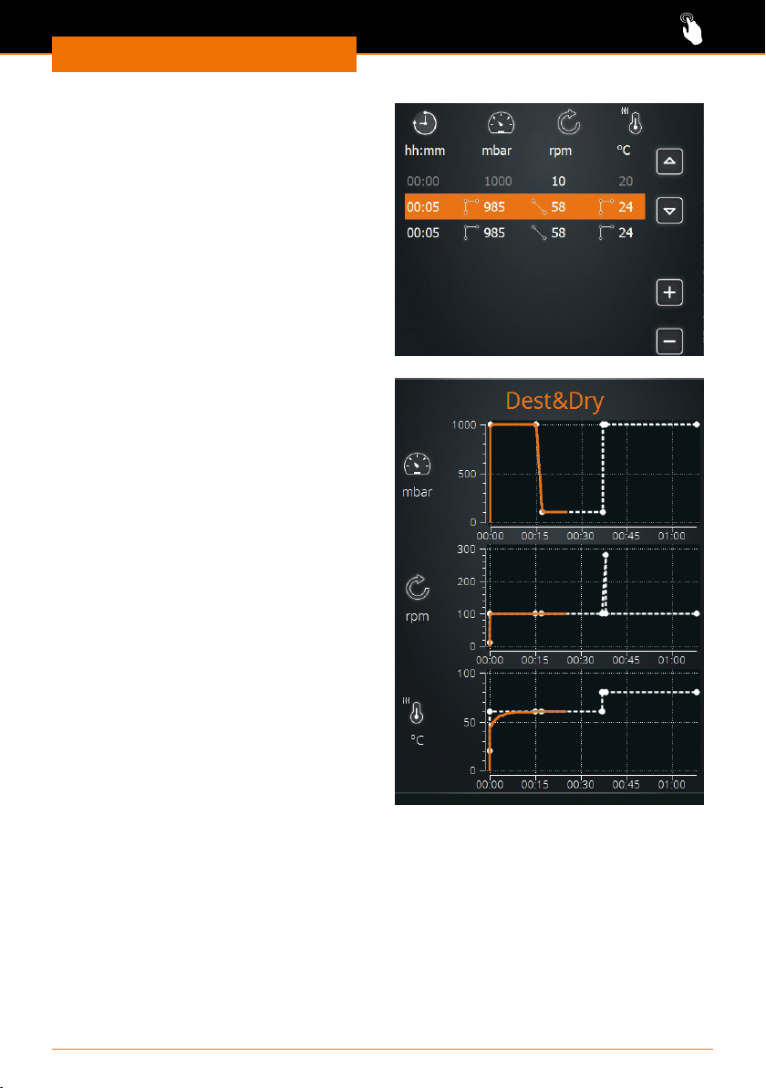
➜ Tap the + symbol.
✓ The rst two lines of your ramp prole
are created.
✓ The default parameters of the rst line
are grayed out.
➜ Tap the second line.
✓ The selected line is highlighted in
orange.
✓ Tap the time indication 00:01.
✓ The number pad is displayed.
➜ Enter the desired duration in the format
hh:mm.
➜ Enter the desired values for all param-
eters this way.
➜ Tap to select the
step symbol
reached as quickly as possible.
➜ Tap to select the
linear symbol
achieved by a continuous increase.
if the value has to be
if the value has to be
47
Page 48
Operation
➜ Tap the symbol + to add more lines to
the prole.
➜ The next line of your ramp prole is
created with the values of the previous
step.
Changing the order of the lines
➜ To change the order of the lines, tap
a line and use the arrows to alter its
position in the prole.
Curve display
➜ Swipe the screen from right to left to
switch to the curve display of the ramp
proles.
✓ The curves of pressure, rotation and
temperature are plotted versus time.
➜ Tap a diagram to enlarge it and tap it
again to shrink it.
Once the processes have started, the
current values are also shown as an orange
curve.
48
Page 49
Operation
Parameters after the end of the ramp
prole
➜ Swipe the screen from right to left to
switch to the list of parameters which
apply after the ramp proles have been
completed.
➜ Determine:
▪ Maintain or stop vacuum
▪ Automatic or manual hysteresis
▪ Continue or stop rotation
▪ Continue or stop heating bath
▪ Hold or raise the lift
▪ Continue or stop the chiller
✓ When parameters have been changed,
the name of the prole gets an “*”.
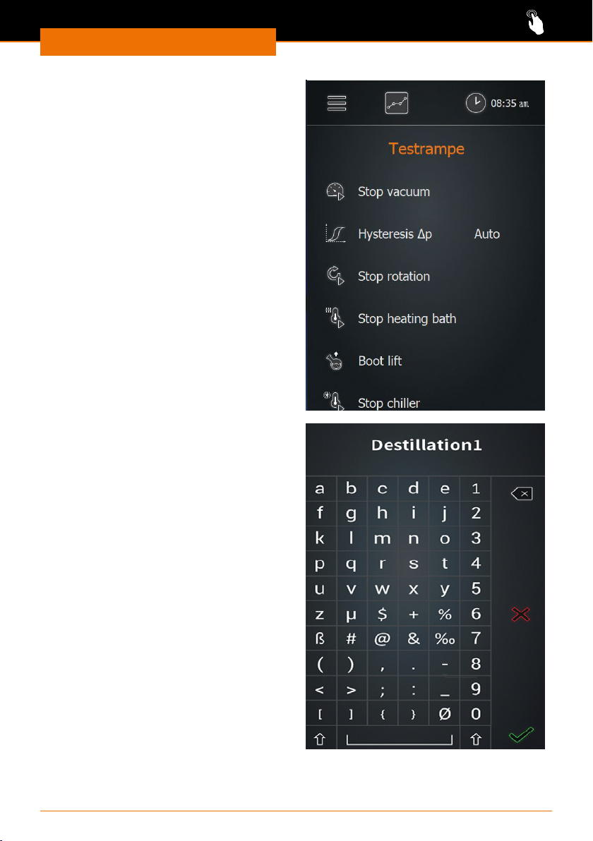
Saving the ramp prole
➜ Return to the ramp prole view.
➜ Tap the “Save” symbol.
➜ Enter a new name and conrm with the
green checkmark.
✓ The new ramp prole is saved and can
be loaded.
49
Page 50
Operation
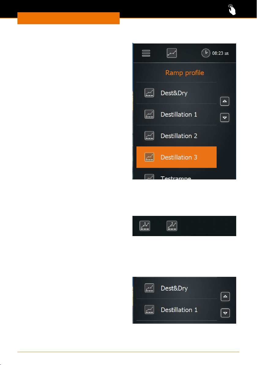
2. Loading ramp proles from the list
✓ You are in the ramp prole mode of the
application “Extended”.
➜ Swipe the screen from right to left to
switch to the list of ramp proles.
➜ Tap the desired ramp prole.
✓ The selected ramp prole is highlighted
in orange.
➜ Tap the “Load” symbol.
✓ The start page is displayed with the
selected ramp prole, and the process
can be started with the pre-set
parameters.
3. Loading existing ramp proles 1 and 2
✓ You are in the ramp prole mode of the application “Extended”.
✓ You assigned ramp proles 1 and 2.
➜ Tap the 1 or 2 symbol (quick-selection
buttons).
➜ The symbol turns orange, the selected
ramp prole is loaded, and you can
start the process immediately.
4. Assigning ramp proles to a quick-selection button
✓ You are in the ramp prole mode of the application “Extended”.
✓ You have selected and loaded a ramp prole from the list.
➜ Tap the 1 or 2 symbol for a couple of
seconds.
✓ The message “Ramp 1 saved” or “Ramp
2 saved” appears, and 1 or 2 symbol is
highlighted in orange.
✓ The favorites 1 and 2 are tagged in the
list of ramp proles.
50
Page 51

Operation
You can assign two proles to the quick-selection buttons (ramp symbol) on the start
screen. This allows you to load these proles directly.
▪ If the quick-selection button have not yet been assigned to a ramp prole, you can
jump to page 2 by tapping on the symbol in order to load a favorite from the list.
▪ If a ramp prole has already been loaded, you can save the current parameters by
keeping the selected quick-selection button pressed.
5. Exporting the ramp proles to a USB stick
It is possible to save the complete list of ramp proles on a USB stick.
✓ You are in the ramp prole mode of the application “Extended”.
✓ The USB stick is inserted in the USB port.
➜ Swipe the screen from right to left to switch to the list of ramp proles.
➜ Tap the “List to USB” symbol and conrm the prompt with OK.
✓ The list is saved.
6. Importing the ramp prole list
If you have saved a ramp prole list on a USB stick, you can import the list.
✓ You are in the ramp prole mode of the application “Extended”.
➜ Insert the USB stick with the ramp prole list into the USB port.
✓ A message pops up asking if you want to import the ramp prole list.
➜ Conrm the prompt.
✓ The ramp proles are imported.
Using automatic mode DAA (Application “Extended“)
In automatic mode DAA, the vacuum is automatically controlled by the AUTOaccurate
sensor. Therefore, this mode can only be used with the optional AUTOaccurate sensor.
This mode oers the following advantages:
▪ Only low quantities of solvent are sucked in by the vacuum pump.
▪ The boiling point is detected automatically and followed up for mixtures.
▪ Mixture distillation is possible without manual adjustments.
▪ Knowledge of the thermodynamic substance data is not required.
▪ It is not necessary to preheat the heating bath: cold starting is possible.
The system controls the vacuum in such a way that the produced vapor quantity
regulates the temperature increase on the AUTOaccurate sensor. The temperature
increase refers to the starting temperature during the deactivated process. It is thus
necessary to have a constant temperature in the chiller prior to the start of the process.
The evaporator checks autonomously for constant temperature and informs you if
necessary.
51
Page 52
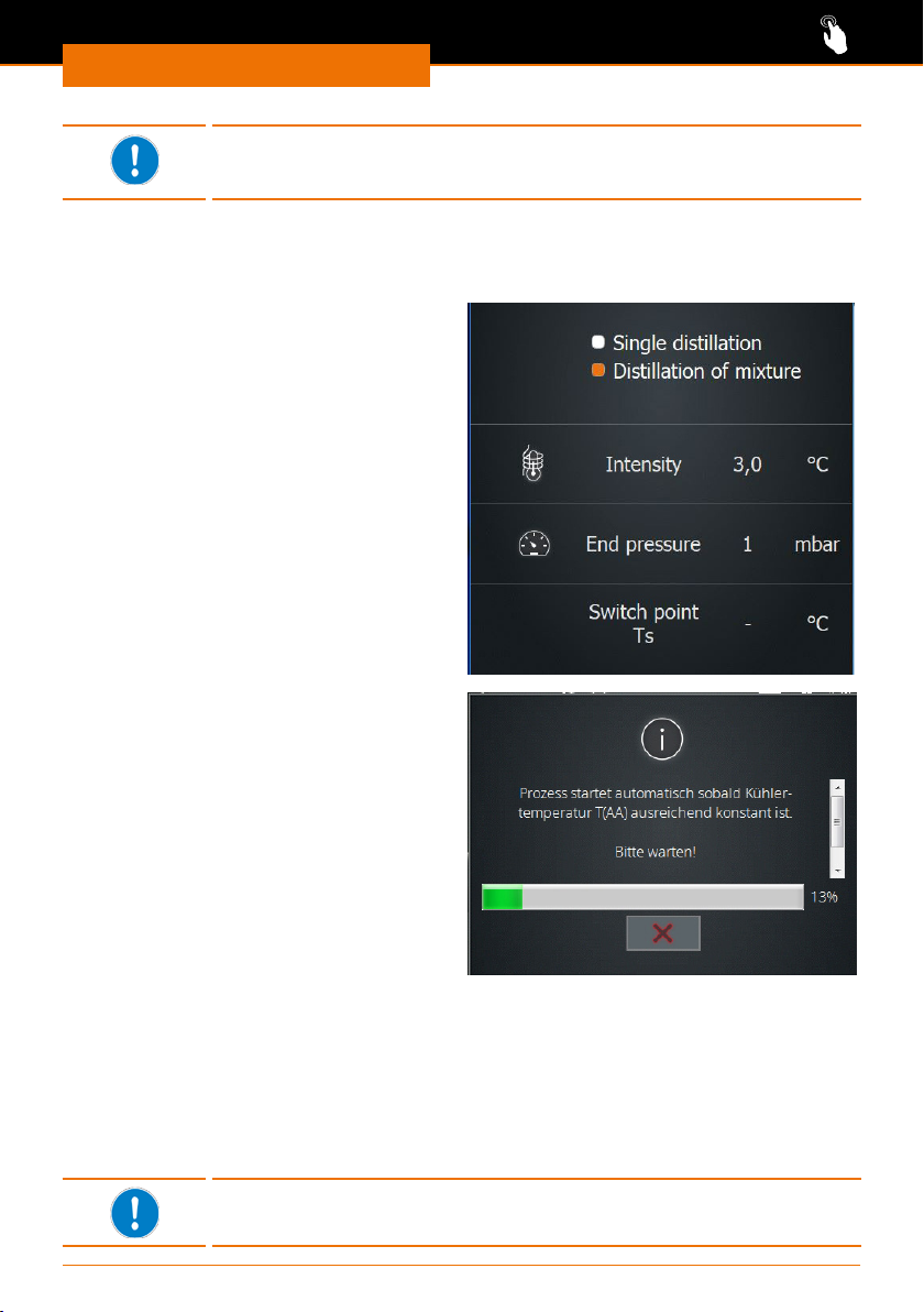
Operation
Since the AUTOaccurate sensor is inserted into the condenser from
above, the automatic mode DAA can only be operated with glassware
sets G3, G3 XL and G6.
✓ You are in the automatic mode DAA of the application “Extended”.
✓ The AUTOaccurate sensor is installed.
➜ Tap “Heat” if you want to heat up the bath.
➜ Swipe the screen from right to left and
select either “single solvent distillation”
or “mixture distillation”.
➜ Dene the “intensity”, i.e. the temper-
ature dierence which will close the
vacuum valve.
➜ For mixture distillation, dene the “nal
pressure”.
The value of the switch point Ts is
displayed after process start. Ts is the sum
of the measured basic temperature and the
indicated intensity.
➜ On the start page, tap “Start DAA”.
✓ The AUTOaccurate sensor measures
the temperature in the condenser for at
least one minute.
✓ The message with the progress
indication appears, and the stopwatch
is started.
If you consider the temperature to be suciently stable, you can end this measuring
process at any time by tapping on “Cancel”.
The current actual value is adopted.
✓ If the basic temperature remains stable (± 0.5 °C) for 1 minute or if you have tapped
on “Cancel”, the DAA control will start.
✓ The pressure is lowered until the temperature at the AUTOaccurate sensor has risen
by the specied intensity and has reached the switch point Ts. The vacuum valve will
be closed, vapor condenses in the condenser.
✓ The pressure regulation stops and will restart when the temperature falls below the
value of the switch point Ts by 0.5°C.
You can also regulate the pressure at any time by tapping on the
symbol “Maintain vacuum”.
52
Page 53
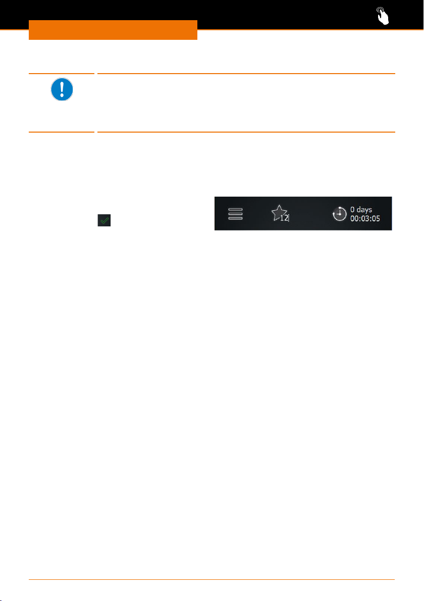
Operation
➜ To stop the process, tap “Stop DAA”.
If you do not tap “Stop DAA”, the evaporation process of the single
solvent distillation will stop automatically after the pressure regulation
has been carried out three times.
The evaporation process of the mixture distillation stops upon reaching
the specied nal pressure.
Starting an application with a timer
Use the timer to specify the duration of a process. As soon as the process has started,
the timer will show the elapsing time.
➜ Tap the timer symbol for about two
seconds and set the desired duration.
➜ Conrm with
The timer can be adjusted for all processes with the exception of the ramp prole mode.
.
53
Page 54
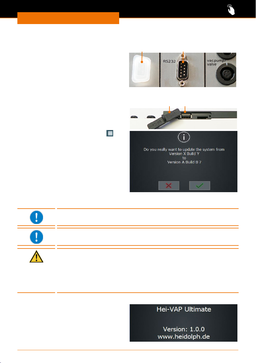
Operation
Interfaces
RS-232 interface
The RS-232 interface is located on the
back side of the control box.
The external chiller uses this interface
to communicate with the rotary evaporator. (see chapter “Assembly”, “Chiller
connection”)
USB port
You can use a USB stick to update the
system.
➜ Insert the USB stick with the new
software into the USB port on the left
side of the control panel.
➜ Tap the “Basic settings” symbol on
the start page.
➜ Tap “System update” at the bottom in
the “Basic settings” menu.
✓ The current version is shown.
✓ Tap the green checkmark to update the
software version.
✓ The installation is started, and the
progress of the installation is displayed.
RS-232 interfaceSealing cap
USB portSafety cover
➜ After nishing the update, remove the USB stick from the device and cover the ports
with the protective cap.
In accordance with the USB 2.0 specication, use the USB port only up
to a maximum of 500 mA.
The SD card port is meant for our service technicians only.
Caution:
Possible damage to the device
If the ports on the device are not covered, liquid may enter and touch
parts carrying current. Penetrating liquids can lead to malfunctions of
the interfaces and result in short circuits.
The interface ports on the back side of the device must be covered at
all times.
Accessing system information
➜ In the “Basic settings” menu, tap
“Information” at the bottom edge of the
screen.
➜ Tap “Firmware” to see the version in use.
➜ Tap “Licenses” to open the license
details.
54
Page 55
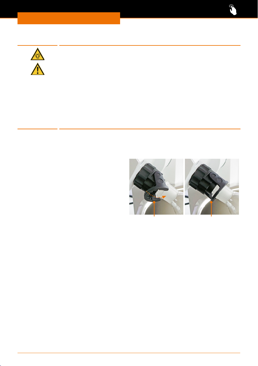
Operation
Evaporating and receiving asks
Warning:
Risk of injury!
If the device is switched on during assembly of the evaporating ask,
it is possible for the device to start rotation due to unintentionally
touching of the control panel; this could result in injuries.
Assemble and remove the evaporating ask only when the device is
switched o.
Warning:
Risk of glass breakage!
If one of the asks is damaged, glass may break, and you may be
seriously injured.
Only work with glass which has no defects. Inspect the glass regularly
for damage.
Assembling and removing the evaporating ask
Assembling the evaporating ask
➜ Loosen the coupling of the Easy Clip
and open the swiveling locking part of
the Easy Clip.
➜ Now guide the evaporating ask over
the ground joint of the vapor tube.
➜ Close the Easy Clip by sliding the
swiveling part of the Easy Clip over the
ange at the evaporating ask so that
the Easy Clip engages.
Easy Clip open Easy Clip closed
✓ The evaporating ask now hangs securely in the Easy Clip lock.
➜ Tighten the Easy Clip on the vapor tube.
Removing the evaporating ask
To remove the evaporating ask:
▪ Heating must be switched o
▪ Rotation must be switched o
▪ The system must be ventilated, and ambient pressure must be established
▪ The lift with the evaporating ask must be in highest position
(see chapter “Start-Up”, section “Heating bath and ask lift”)
▪ The device must be switched o
55
Page 56
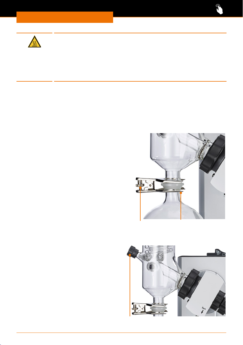
Operation
Warning:
Risk of burns!
Contact with the evaporating ask can cause severe burns if it has not
cooled down suciently.
▪ Always allow the evaporating ask to cool down before removing it.
▪ The maximum temperature must not exceed 50 °C / 122 °F.
▪ Wear protective clothing.
▪ Wear safety gloves to ensure a secure grip.
➜ Loosen the coupling of the Easy Clip ask clamp from the vapor tube using 1-2
counterclockwise turns.
➜ Grip the evaporating ask with one hand and open the Easy Clip.
➜ Carefully remove the evaporating ask.
Assembling and removing the receiving ask
Assembling the receiving ask
➜ Hold the receiving ask with the
opening facing up against the ange of
the condenser.
➜ Slide the ground joint clamp over
the ange on the condenser and the
receiving ask.
➜ Carefully tighten the knurled screw of
the ground joint clamp.
✓ The receiving ask is attached.
Removing the receiving ask
➜ Grip the receiving ask with one hand.
➜ Loosen the knurled screw of the ground
joint clamp.
➜ Remove the ground joint clamp.
Knurled screw Ground joint clamp
Ventilation
The system can be ventilated manually
using the ventilation cap:
➜ For ventilation, turn the ventilation cap
half a turn or a maximum of 1 turn
counterclockwise to the left.
✓ The ventilation speed increases with the
rotation.
➜ Slowly turn the ventilation cap clockwise
to the right.
✓ The air feed will close slowly.
Ventilation cap
56
Page 57
Cleaning and Maintenance
Cleaning
The housing and surfaces of the device can be cleaned using a damp cloth and, if
required, a mild soap solution.
Warning:
Risk of electric shock!
Liquids penetrating into the device could cause the device to become
electrically live if it is still connected to the power supply.
Before cleaning the device:
▪ Switch the device o.
▪ Disconnect the power cord plug.
Caution:
Damage to the device
Liquids penetrating into the device could damage the electronics.
Wipe the surfaces only with a damp cloth and not a wet one.
Caution:
Damage to surfaces
The surfaces could be damaged by improper cleaning.
Do not use the following under any circumstances:
▪ Chlorine bleach or cleaning agents containing chlorine
▪ Substances containing solvents (e.g. acetone)
▪ Ammonia
▪ Abrasive cleaning agents such as cleaning wool, scouring agents or
cleaning agents with metallic components
Cleaning the heating bath
Rust spots on the bottom of the heating bath after shorter or longer use are caused by
the deposition of foreign substances (iron particles or rust particles).
Cleaning and Maintenance
Rust spots can be removed by cleaning with a commercial available
stainless steel polish.
Lime deposits can be removed easily by cleaning with a commercially
available lime solvent, for example based on citric acid or acetic acid.
Please follow the instructions of the cleaning agent manufacturer.
Cleaning of coated glassware sets
If the cleaning temperature is too high, the coating of the
glassware sets can be damaged.
Rinse coated glass parts only up to a maximum temperature of 50 °C.
57
Page 58

Cleaning and Maintenance
Maintenance
Caution:
Damage to the device
When operating with a damaged PTFE seal, the desired vacuum cannot
be achieved, your sample can be contaminated, and your device can
be damaged.
Never work with a damaged or worn PTFE seal. Examine the PTFE seal
regularly and replace it as needed.
The device requires no maintenance. Any repairs that may be required must be
performed by a specialist authorized by Heidolph Instruments.
In this case, contact your authorized Heidolph dealer or a representative of Heidolph
Instruments.
58
Page 59
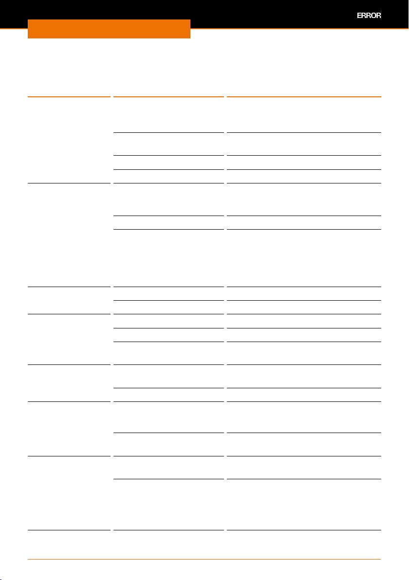
Troubleshooting
Malfunctions and remedies
Errors on the
device
▪ The device
cannot be
switched on
▪ Display remains
dark after
switching on
Device does not
heat
Drive does not turn Rotation is switched o. Press rotation knob
Motor lift does not
run
No vacuum ON/OFF switch at the
Vacuum insucient Leak in system ▪ Check seals and connections
Device switches
suddenly o
Possible cause Remedy
No power supply Check that the plug is connected
Defective fuse Replace device fuses (see chapter
ON/OFF switch o Switch ON/OFF switch on
ON/OFF switch defective Contact local dealer
Connecting cable to
heating bath is not
attached
Bath heating defective Contact local dealer
Overheating protection
activated
Drive defective Contact local dealer
Lift is at end stop Move lift in the opposite direction
Lift is at height stop Change height stop
Mechanics / Motor
defective
vacuum pump o
Vacuum valve defective Replace vacuum valve
Vacuum pump defective Follow information from the vacuum
Fuses defective Replace fuse (see chapter “Assembly,
When pressure is
detected, the device is
emergency stopped, see
the settings for excess
pressure and leakage.
Troubleshooting
properly to the power socket and the
device
“Assembly, Electrical Connection”)
Attach connecting cable
▪ Let the heating bath cool down
▪ Emptying the heating bath
▪ Reset overheating protection
(see the following section
“Resetting the temperature
limiter”)
Contact local dealer
Switch ON/OFF switch on
▪ Check ground glass joints, grease if
necessary
pump manufacturer
Electrical Connection”)
▪ Check system and switch device on
again
▪ Calibrate the vacuum sensor
59
Page 60

Troubleshooting
Vapor temperature
is not displayed
Automatic mode
(DAA) cannot be
selected
Control box not
connected or
defective
Ventilation valve
defective
Vacuum valve
not attached or
defective
Vacuum pump
not attached or
defective
Vapor temperature sensor
not attached
Vapor temperature sensor
defective
Temperature is outside of
measuring range
AUTOaccurate sensor not
attached
AUTOaccurate sensor
defective
Temperature outside of
measuring range
Control box not connected
or defective
Short circuit in the ventilation valve
Vacuum valve is not
attached or the connection between control
box and vacuum valve is
interrupted
Short circuit in the
vacuum valve
Vacuum pump is not
attached or the connection between control box
and vacuum pump is
interrupted
▪ Attach vapor temperature sensor or
check connection
▪ If needed, switch the device o and
on again
▪ Inspect vapor temperature sensor
for defects
▪ Contact service, if needed, replace
sensor
Let sensor warm up or cool down
▪ Attach AUTOaccurate sensor or
check connection
▪ if needed, switch the device o and
on again
▪ Inspect AUTOaccurate sensor for
defects
▪ Contact service, if needed, replace
sensor
Let sensor warm up or cool down
▪ Check connection between control
box and evaporator
▪ Contact service
Contact service
▪ Connect vacuum valve
▪ Check connection between control
box and vacuum valve
▪ Contact service
Contact service
▪ Attached vacuum pump
▪ Check connection between control
box and vacuum pump
60
Page 61

Troubleshooting
After the rotary evaporator has been switched on, it checks the attached components.
The scope of functions depends on the devices attached.
Missing
component
Control box Control box is not
Vacuum valve or
vacuum pump
Vapor temperature
sensor:
AUTOaccurate
sensor
Description /
Response of the device
attached:
▪ Vacuum value is not
shown in display
▪ Vacuum control deacti-
vated
Vacuum valve or vacuum
pump is not attached:
▪ Vacuum control is
deactivated
The sensor for determining the vapor
temperature is not
attached:
▪ Steam temperature is
not displayed
The sensor for controlling
the automatic mode DAA
is not attached:
▪ “Automatic (DAA)”
mode is deactivated
Remedy
▪ Attach control box and components
▪ Switch the device o and then on
again
▪ Attach components
▪ Switch the device o and then on
again
▪ Attach components
▪ Switch the device o and then on
again
▪ Attach components
▪ Switch the device o and then on
again
61
Page 62
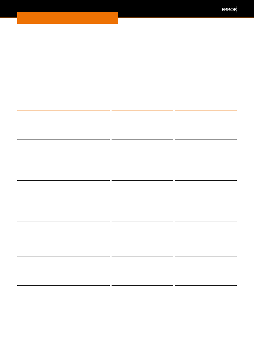
Troubleshooting
Analyzing the list of errors
You can view a compilation of the following warnings and errors, which appear on the
display during operation, at a later time in order to analyze your process.
All in all, a maximum of 32 errors is stored. After that, older messages are overwritten by
newer ones.
➜ In the menu bar of the “Basic settings” menu, tap “Error list” to view information,
errors and warnings.
✓ An error history is displayed showing the corresponding date and time.
➜ To view details, tap the individual entries.
The following messages/errors are displayed.
Error messages on display Cause Remedy
Warning:
Transportation lock activated!
Please move lift upward and switch
the device o and then on again.
Warning:
The vapor temperature sensor is
defective or not attached!
Warning:
The AUTOaccurate sensor is defective or not attached!
Warning from chiller:
Temperature has fallen below the
lower limit!
Warning from chiller:
Temperature has exceeded the
upper limit!
Warning from chiller:
Filling level of thermal uid too low!
Warning:
Heating bath
Careful! Hot!
Error
The AUTOaccurate sensor is defective or the temperature is below the
measuring range.
Error
The AUTOaccurate sensor is defective or the temperature is above the
measuring range.
Error
The vapor temperature sensor is
defective or the temperature is
below the measuring range.
The transportation lock
is still activated.
Sensor is not attached
or defective
Sensor not attached or
defective
Chiller temperature too
low
Chiller temperature too
high
Not enough cooling
uid
Heating bath temperature
> 50 °C
Defective sensor or
temperature below
-40 °C
Defective sensor or
temperature above 173
°C
Defective sensor or
temperature below
-40 °C
▪ Remove transpor-
tation lock if needed
▪ Move lift upward
▪ Switch the device o
and then on again
Check vapor temperature sensor and replace
it if needed
Check AUTOaccurate
sensor and replace it if
needed
Increase chiller temperature
Reduce chiller temperature
Add cooling uid
Let the heating bath
cool down
▪ Check AUTOaccurate
sensor and replace it
if needed
▪ or increase temper-
ature
▪ Check AUTOaccurate
sensor and replace it
if needed
▪ or reduce temper-
ature
▪ Check vapor temper-
ature sensor and
replace it if needed
▪ or increase temper-
ature
62
Page 63

Troubleshooting
Error messages on display Cause Remedy
Error
A data bus error has occurred.
Switch the device o and on again
Error
A temperature above the safety
temperature was measured in the
heating bath. The temperature
measurement unit is defective or
the medium lled in was too hot.
Switch the device o and on again!
Error
An implausible temperature dierence was measured between the
heating bath sensors. The temperature measurement unit is defective.
Switch the device o and then on
again
Error
The temperature sensor for the
heating bath control is defective
(hardware monitoring unit).
Switch the device o and on again
Error
The temperature sensor for the
heating bath control is broken or
the lled in bath uid is too hot.
Switch the device o and on again
Error
The temperature sensor for the
heating bath control has shorted or
the bath uid was added too cold.
Switch the device o and on again
Error
The lift motor is defective or has
jammed!
Switch the device o and on again
Error
The pressure exceeds the maximum
permissible excess pressure!
Error
The set safety pressure was
exceeded.
Error in data bus,
e.g. a bus node was
disconnected during
operation.
Heating bath temperature is too high or the
temperature measurement unit is defective.
Error in temperature measurement of
heating bath
Heating bath control is
defective, perhaps due
to short circuit
Heating bath control is
defective or temperature in the heating bath
>217°C
Heating bath control
is defective, perhaps
due to short circuit or
temperature <0 °C
Defective or jammed
lift motor
Pressure in the vacuum
system is too high
Pressure in the vacuum
system is too high
▪ Switch the device o
and on again!
▪ Let the heating bath
cool down
▪ Switch the device o
and on again
▪ Contact service
Switch the device o
and then on again
▪ Switch the device o
and on again
▪ Contact service
▪ Let the heating bath
cool down
▪ Switch the device o
and on again
▪ Contact service
▪ Heat up heating bath
▪ Switch the device o
and then on again
▪ Contact service
▪ Switch the device o
and on again
▪ Contact service
▪ Reduce pressure in
the vacuum system
▪ Reduce pressure in
the vacuum system
▪ If required, adjust
the set maximum
pressure
63
Page 64

Troubleshooting
Error messages on display Cause Remedy
Error
The pressure sensor is not attached
or defective.
Error
Defective communication with the
pressure sensor!
Error
The ventilation valve is not
connected or is defective.
Error
The ventilation valve is defective.
Error
The vacuum valve is not attached or
defective.
Error
The vacuum valve is defective.
Error
The vacuum pump is not attached
or defective.
Error
Vacuum module:
Connection error between base
plate and vacuum plug-in board.
Please check the cable connection!
Error
Chiller module:
Connection error between base
plate and chiller plug-in board.
Please check the cable connection!
Error
A communication error between
base plate and control panel has
occurred!
Error
The rotary drive is overloaded or
defective!
Switch the device o and on again!
Error
Alarm from the chiller:
Circuit board is too hot
Pressure sensor not
attached or defective
or control box is not
connected correctly.
Hardware fault on the
vacuum plug-in board
Ventilation valve not
connected or defective
or control box is not
connected correctly.
Short circuit in the
ventilation valve
Vacuum valve not
attached or defective
or control box is not
connected correctly.
Short circuit in the
vacuum valve
Vacuum pump not
attached or defective
or control box is not
connected correctly.
Bus error of the
component, e.g. due
to plugging/unplugging
during operation.
Bus error of the
component, e.g. due
to plugging/unplugging
during operation.
Bus error of the
component, e.g. due
to plugging/unplugging
during operation.
Drive motor defective
or overloaded
Chiller overloaded Switch chiller o and
▪ Check and re-attach
vacuum sensor
▪ Check connection of
control box
▪ Contact service
▪ Replace vacuum
plug-in board
▪ Check and re-connect
the ventilation valve
▪ Check connection of
control box
▪ Contact service
▪ Check and re-attach
vacuum valve
▪ Check connection of
control box
▪ Contact service
▪ Check and re-attach
vacuum pump
▪ Check connection of
control box
▪ Check cable
connection
▪ Switch the device o
and on again!
▪ Check cable
connection
▪ Switch the device o
and on again!
▪ Check cable
connection
▪ Switch the device o
and on again!
▪ Switch the device o
and on again!
▪ Contact service
let it cool down
64
Page 65
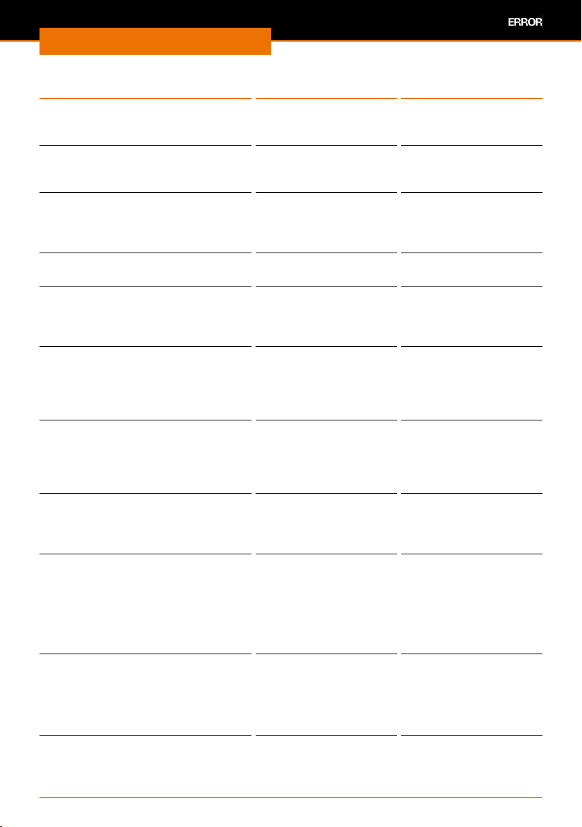
Troubleshooting
Error messages on display Cause Remedy
Error
Alarm from the chiller:
Pump is overheated
Error
Alarm from the chiller: Hardware
fault!
Error
Update unsuccessful! Use the main
power switch to switch the device
o and on again!
Error
Update unsuccessful!
Information
Reset system to factory settings?
The device must be restarted
afterward.
Information
The process will start automatically
as soon as the chiller temperature
T(AA) is suciently constant. Please
wait!
Information
The bath temperature exceeds the
set max. bath temperature.
The max. bath temperature must be
adjusted!
Information
The pressure exceeds the max.
permissible excess pressure.
Please adjust the pressure!
Information
A calibrated external pressure
gauge is required.
Please enter the atmospheric
pressure indicated on the external
pressure gauge and conrm the
value with OK!
Information
Calibration will stop the running
processes.
Do you really want to calibrate the
p-sensor?
Chiller overloaded Switch chiller o and
Fault in the chiller
hardware
Software update
unsuccessful
Software update
unsuccessful
Reset to factory setting
opened
Automatic mode DAA
was started
The heating bath
temperature exceeds
the set max. heating
bath temperature.
The pressure detected
exceeds the maximum
excess pressure value
Pressure sensor calibration has started
Pressure sensor calibration was started
let it cool down
▪ Switch the device o
and on again!
▪ Contact service
Switch the device o
and on again!
Switch the device o
and on again!
Switch the device o
and on again
▪ Wait
▪ or cancel and start
without constant
temperature
Adjust the max.
heating bath temperature
Reduce pressure below
the excess pressure
value.
Enter/correct the actual
atmospheric pressure
value
▪ Conrmation will stop
all running processes.
▪ Exception: if only
rotation has started,
it will continue
running
65
Page 66
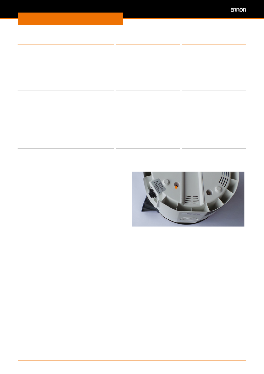
Troubleshooting
Error messages on display Cause Remedy
Information
Please close all openings on the
evaporator system and evacuate it.
When the pressure value has
become stable, enter the value
indicated on the external pressure
gauge and conrm it with OK!
Information
Vacuum sensor and/or
AUTOaccurate sensor not available!
Automatic mode (DAA) cannot be
started.
Information
No ramp loaded
Ramp mode cannot be started!
The actual atmospheric
pressure value has
been entered
Vacuum sensor and/or
AUTOaccurate sensor
are not attached,
automatic mode (DAA)
cannot be started.
No ramp prole loaded ▪ Load ramp prole
Enter/correct the actual
value of the
current minimum
vacuum pressure
Attach vacuum sensor
and/or AUTOaccurate
sensor
▪ Start ramp prole
mode
Resetting temperature limiter
➜ Switch the device o Remove the
cooled evaporating ask
➜ Disconnect the heating bath plug and
remove the heating bath.
➜ If necessary, empty the heating bath
and turn it over.
➜ Use a suitable object to briey press
the red button on the bottom until it
clicks audibly into place.
✓ Reset the temperature limiter
If you experience a malfunction that cannot be resolved using the information listed
above, please inform your authorized Heidolph dealer immediately.
Temperature limiter
66
Page 67
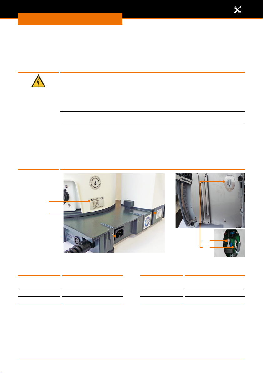
Assembly
Electrical connections
▪ Fuses must only be replaced by a professional electrician.
▪ Repairs to the device must only be carried out by a qualied electrician
approved by Heidolph Instruments. Improper repairs could result in serious
dangers. Please contact your specialist dealer if the device needs to be repaired.
Warning:
Risk of electric shock
The device must be connected to an earthed power socket.
The rated voltage for the device and the supply voltage must be the
same. The rated voltage for the device can be found on the rating plate
on the rear of the device.
The device is supplied with a grounded power cord.
plug is replaced, the new plug must have a protective conductor!
If the device is still connected to power while changing the fuse, you
might get in contact with live parts.
Prior to replacing the fuse ensure that the unit is switched o and pull
the plug from the electric socket. Only use original spare fuses from
Heidolph Instruments.
After changing a fuse check the device for safe operating condition
according to IEC 61010-1.
Heating bath
rating plate
Base device
rating plate
Assembly
In case the original
Device socket
Color code for electrical connections:
Europe North America
GREEN/YEL-
LOW
BLUE N: Neutral conductor WHITE N: Neutral conductor
BROWN P: Phase BLACK P: Phase
The device is connected to the mains with the power cord supplied. The power connection
is located on the rear of the housing.
For countries where a dierent plug than the standard plug supplied is used:
▪ The plug supplied may only be changed by a professional electrician.
▪ If you wish to use an adapter, ensure that it is grounded and approved in accordance
with the local regulations.
▪ Wiring, adapter and plug must at least meet the electrical power stated on the rating
plate.
PE: Protective
conductor (Earth)
GREEN PE: Protective
67
Device fuses
conductor (Earth)
F4
F2
Page 68
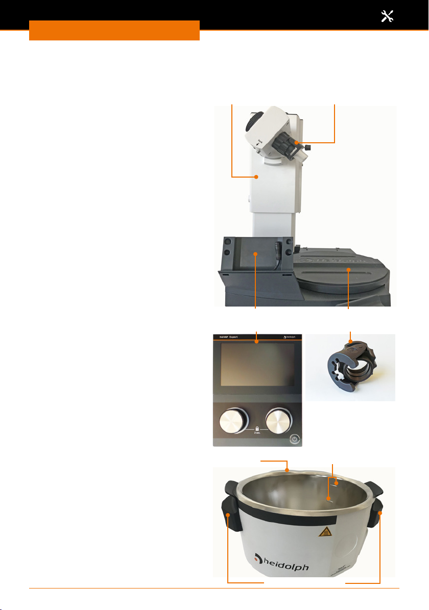
Assembly
Installation
Assembly parts
Base device
Flask lift
Easy Clip ask clamp
Control panel bracket
Control panel Operating panel (example) Easy Clip
Heating bath Min.-/Max. marksPouring rim
Insulated handles
68
Base plate heating bath
Page 69
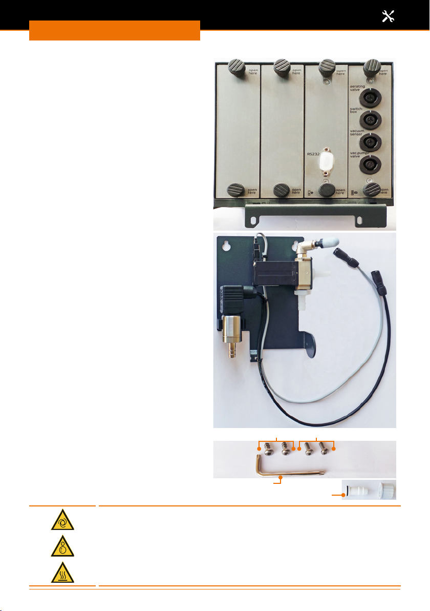
Assembly
Control box
Vacuum manifold
Small parts for assembly
▪ 1x tube nipple with screw cap
(for vacuum connection)
▪ 2x metric screws
▪ 2x threaded screws
▪ 1x torx wrench
Warning:
Risk of crushing! Risk of burns!
If the device is switched on, the heating or rotation can be started
unintentionally. This may injure and burn your hands.
Install the device only when the device is switched o.
Screws: Plastic - metric
Torx wrench
Tube nipple with screw cap
69
Page 70
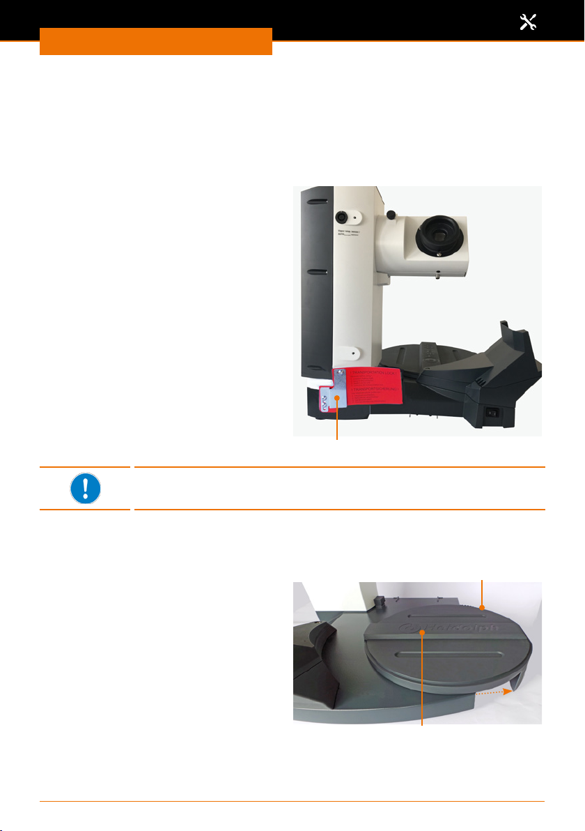
Assembly
Transportation lock
(Motor lift only)
The transportation lock must be removed before start-up of the device. Retain the transportation lock for a possible return.
The transportation lock consists of three M5x8 screws and a connecting plate with holes
for xing the position.
Remove transportation lock prior to
start-up
✓ The base device is positioned on a
stable, level surface.
➜ Connect the heating bath
➜ Connect the control panel.
➜ Switch the device on.
➜ Use the provided Allen key to loosen
all 3 screws and remove the metal
sheet of the transportation lock.
➜ Move the ask lift to the highest
position.
➜ Switch the device o.
✓ You can now switch the device back on
and put it back into operation.
➜ Retain all parts of the transportation
lock for later use.
Transportation lock
To deactivate the additional electronic transportation lock, the device
must be switched o once when the lift is in the highest position.
Heating bath
Insert the heating bath
✓ A sliding base plate with a raised guide
rail is located on the right side of the
base device.
Base plate
Guide rail
70
Page 71
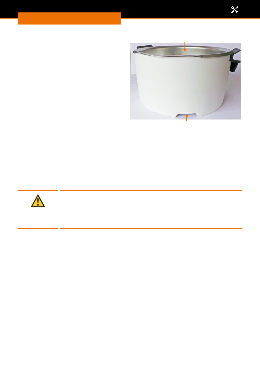
Assembly
➜ Place the heating bath with the recess
to the left on the guide rail.
➜ Move the heating bath slightly to the
right and left, so that it locks securely.
Moving the heating bath
When using larger evaporating asks or adapters between evaporating ask and vapor
tube, it may be necessary to increase the distance between the heating bath and the
drive.
✓ The base device is positioned on a stable, level surface.
✓ There is about 20 cm space for movement on the same base to the right of the
heating bath.
➜ Hold the heating bath by both handles and pull it to the right to the desired position.
Caution:
Risk of crushing!
When moving the heating bath towards the device, your ngers may
get caught between heating bath and device.
When moving the heating bath, always hold it at the insulated handle.
Heating bath
Recess
71
Page 72
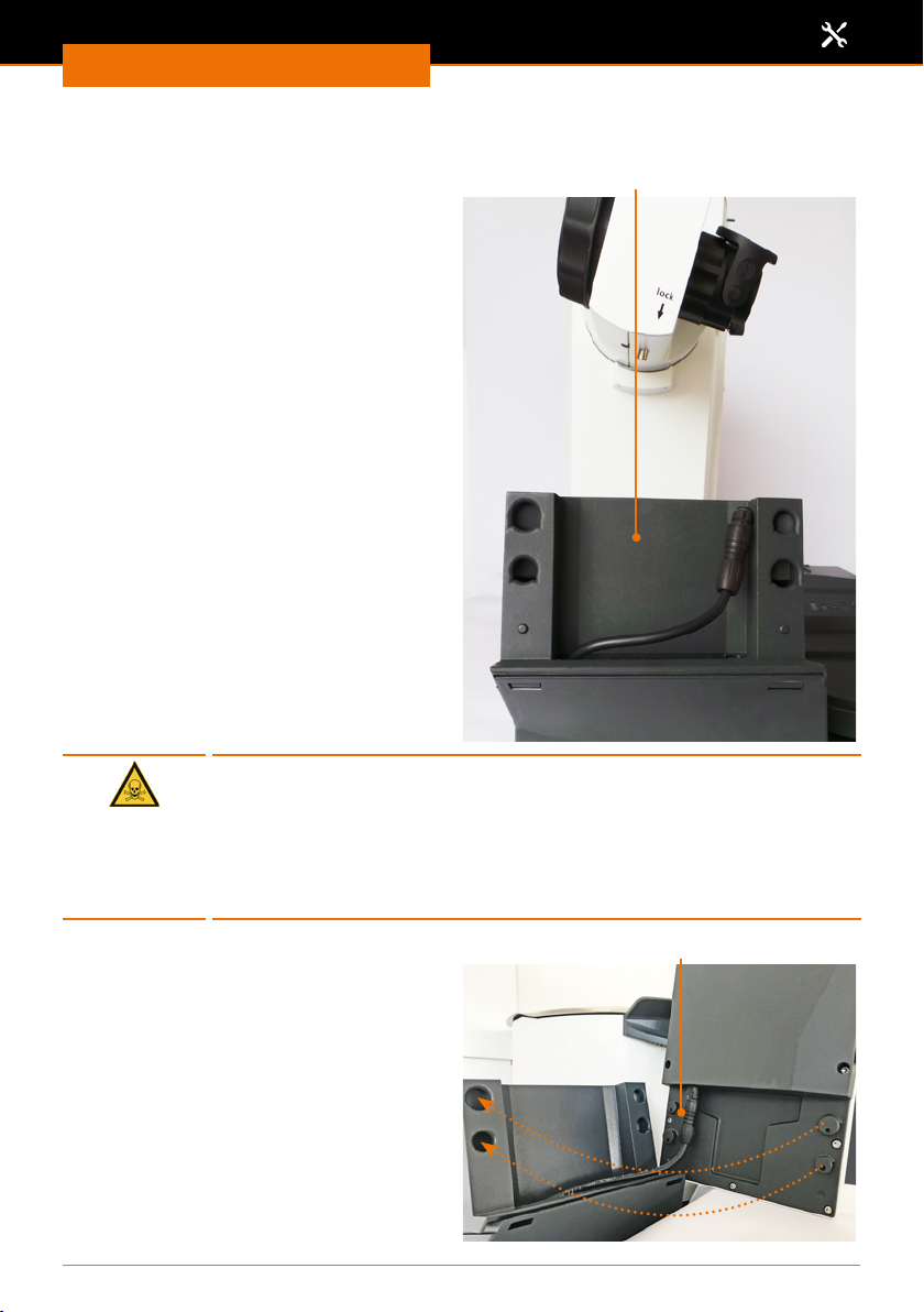
Assembly
Control panel
The control panel support is located in
front of the ask drive.
Warning:
Risk of poisoning!
If you operate the device inside a fume hood and have to reach the
control panel during a running process, you may be endangering your
health when you open the fume hood.
Remove the control panel and position it outside the fume hood. (see
also chapter "Scope of supply and accessory“)
Control panel bracket
Mounting the control panel on the
bracket
➜ Connect the cable from the back side
of the control panel to the connection
cable in the support.
➜ Place the control panel on the support
so that the buttons on the back of the
panel are seated in the recesses of the
support.
➜ Then slide the control panel down to
the stop.
✓ The control panel is now ready for use.
Connection cable
72
Page 73
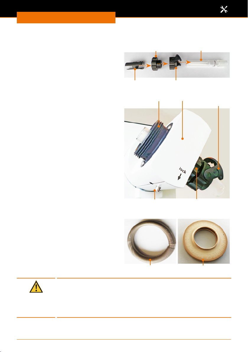
Assembly
Vapor tube
Assembly parts
▪ Vapor tube
▪ Easy Clip ask clamp
▪ Coupling
▪ Clamping sleeve
The Easy Clip ask clamp is pre-mounted
in the NS29 size. The Easy Clip NS24 is
included for smaller asks.
When the device is delivered, the coupling
for the vapor tube and the condenser are
pre-assembled.
➜ Press and hold the locking knob below
"lock" for a quarter turn.
➜ Unscrew the coupling of the vapor tube
together with the Easy Clip to the right
of the drive.
➜ Unscrew the coupling for the
condenser to the left of the drive.
Vapor tubeVapor tube coupling
Clamping sleeve Easy Clip ask clamp
Condenser
coupling
Vapor tube locking
knob
Drive
Easy Clip ask
clamp
Vapor tube coupling
➜ Remove the tension spring and the
PTFE seal on the condenser side.
Caution:
Contamination of your sample, device damage
A damaged seal can prevent reaching the desired vacuum, can
contaminate your sample or damage your device.
Never work with a damaged or worn PTFE seal. Inspect the PTFE seal
regularly and replace it if necessary.
Tension spring PTFE seal
73
Page 74
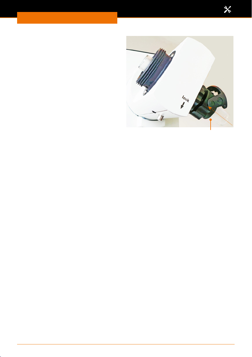
Assembly
✓ Coupling and Easy Clip are screwed
together
➜ Push the coupling of the vapor tube
together with the Easy Clip onto the
vapor tube. (Direction and sequence as
shown under “Assembly parts”)
➜ Push the clamping sleeve with the
bead toward the glass onto the vapor
tube until it clicks into place.
➜ Insert the vapor tube with the
clamping sleeve rst from below into
the drive and screw it tight.
➜ Press the locking knob during the last
quarter turn.
Vapor tube, Easy Clip and coupling
74
Page 75
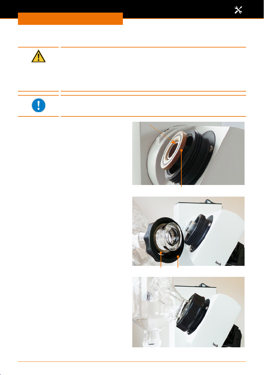
Assembly
Condenser
Warning:
Risk of glass breakage!
If a glass component is damaged, glass may break, and you may be
seriously injured.
Only work with glass which has no defects. Inspect the glass regularly
for damage.
The coated glassware sets from Heidolph Instruments reduce the
risk of injury in the event of glass breakage. However, they are only
suitable for a temperature range up to max. 80 °C.
PTFE seal
➜ Slide the PTFE seal with the mark
"Motor Side" rst forward onto the
vapor tube.
✓ The PTFE seal has been pushed to the
stop.
Condenser:
Glassware set G1, G3 and G3 XL
➜ Slide the coupling for the condenser
over the chiller ange.
➜ Slide the tension spring over the chiller
ange.
➜ Hand-tighten the chiller with the
coupling on the drive.
PTFE seal
✓ The chiller is mounted on the drive.
CouplingTension spring
75
Page 76
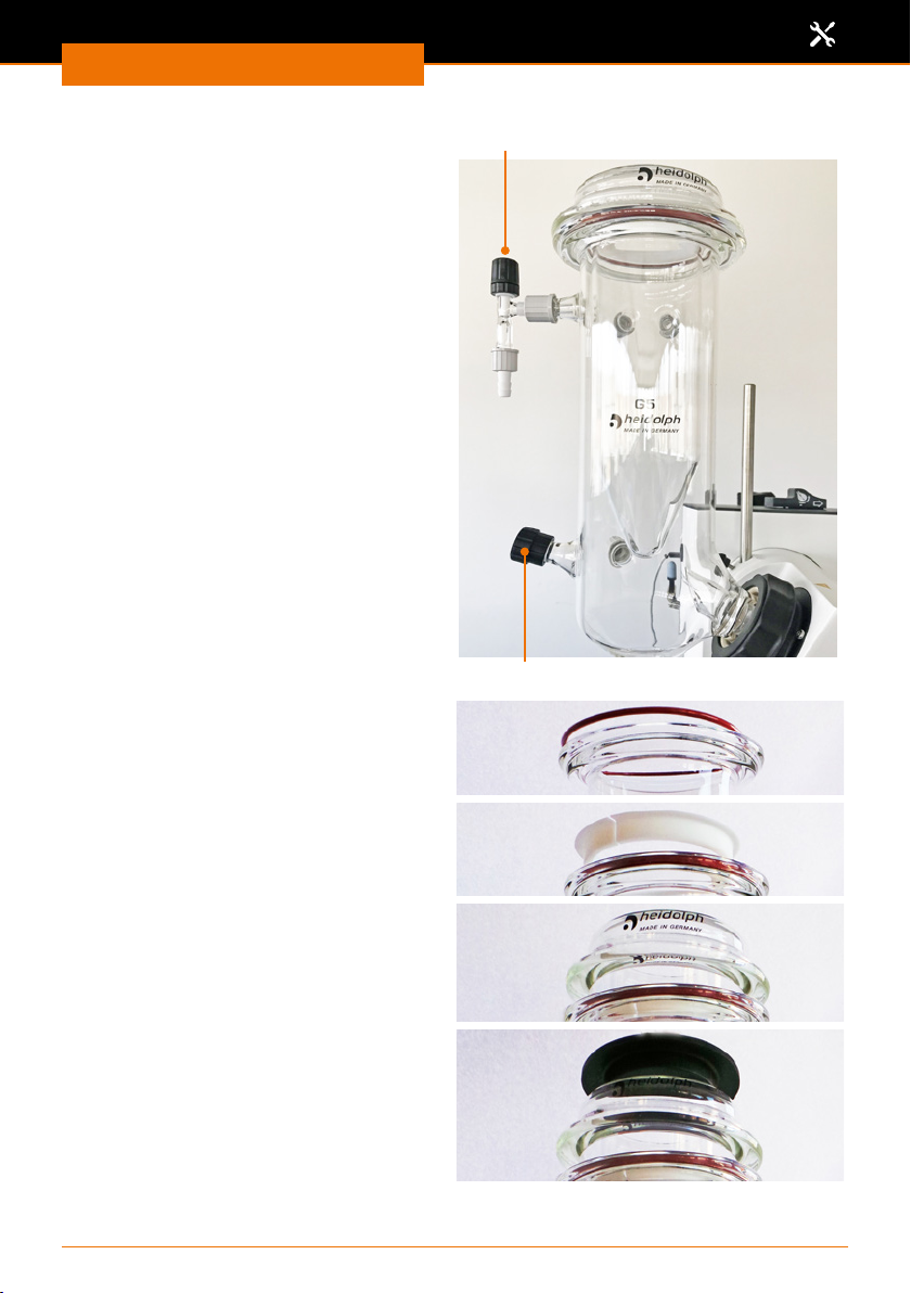
Assembly
Condenser:
Glassware set G5 dry ice cooler
✓ The chiller is mounted on the drive.
➜ Screw the ventilation cap onto the
opening opposite the vapor tube.
➜ If you are working with inert gas,
screw the inlet hose with inert gas
valve onto the opening above the
ventilation cap.
➜ Place the red seal ring in the groove at
the top of the chiller ange.
Inert gas valve
Ventilation cap
➜ Place the white PTFE ring above it with
the collar facing upwards in the chiller
ange.
➜ Now insert the cold trap into the
condenser.
✓ The ange is drawn in by the vacuum
and the system is closed vacuum-tight
by the installed seal.
➜ Place the black lid on top to protect
your dry ice.
76
Page 77
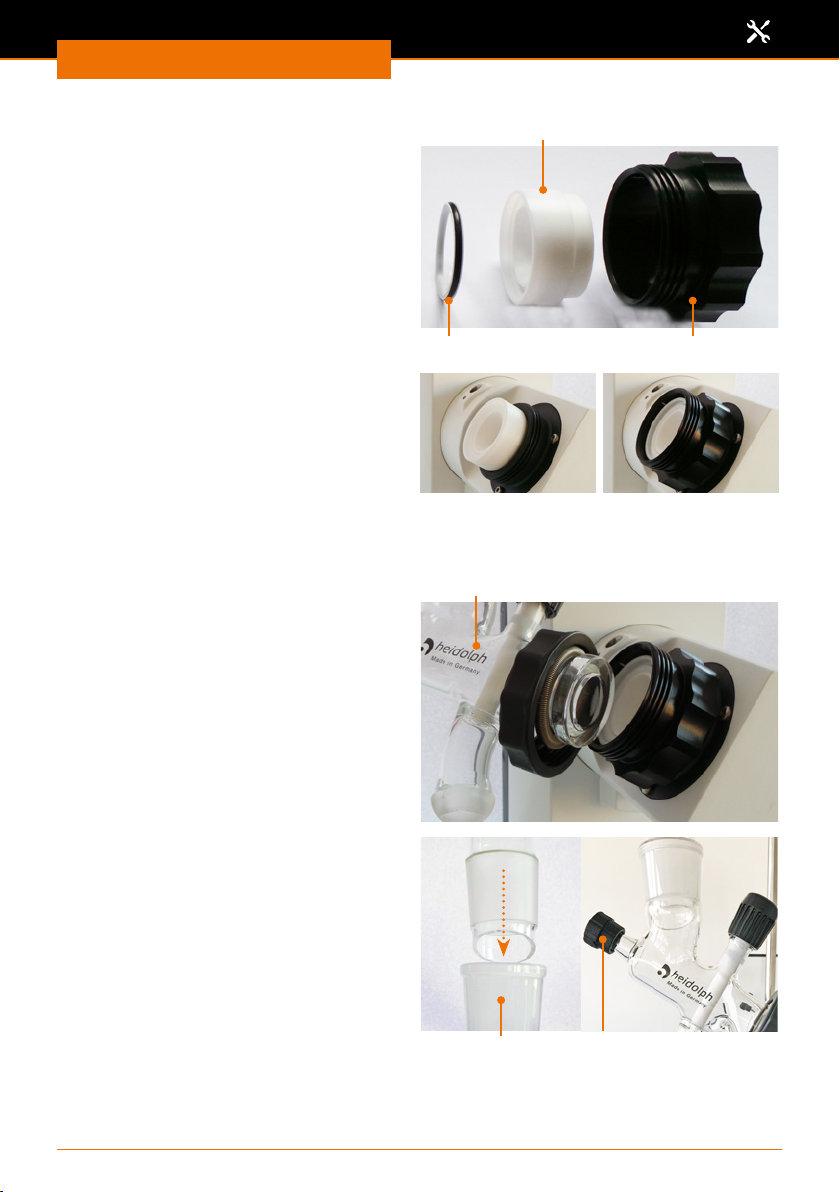
Assembly
Condenser: Glassware set G6
(chiller for reux distillation)
Additional assembly parts at the vapor tube:
▪ PTFE seal ring
▪ Spacer sleeve
▪ Additional coupling
✓ The vapor tube is installed together
with the PTFE seal.
➜ Install the PTFE seal ring in the spacer
sleeve
➜ Install the spacer sleeve together with
the PTFE seal ring with the narrow
side rst in the vapor tube on the
condenser side
➜ Screw the additional coupling over it
with the male thread pointing left.
➜ Tighten the distributor with the
coupling including the tension spring
onto the male thread.
✓ The distributor is installed.
Spacer sleeve
PTFE seal ring
Distributor
Additional coupling
➜ Insert the chiller into the upper ground
glass joint on the distributor.
➜ Screw the ventilation cap onto the
opening opposite the vapor tube.
Distributor Ventilation cap
77
Page 78
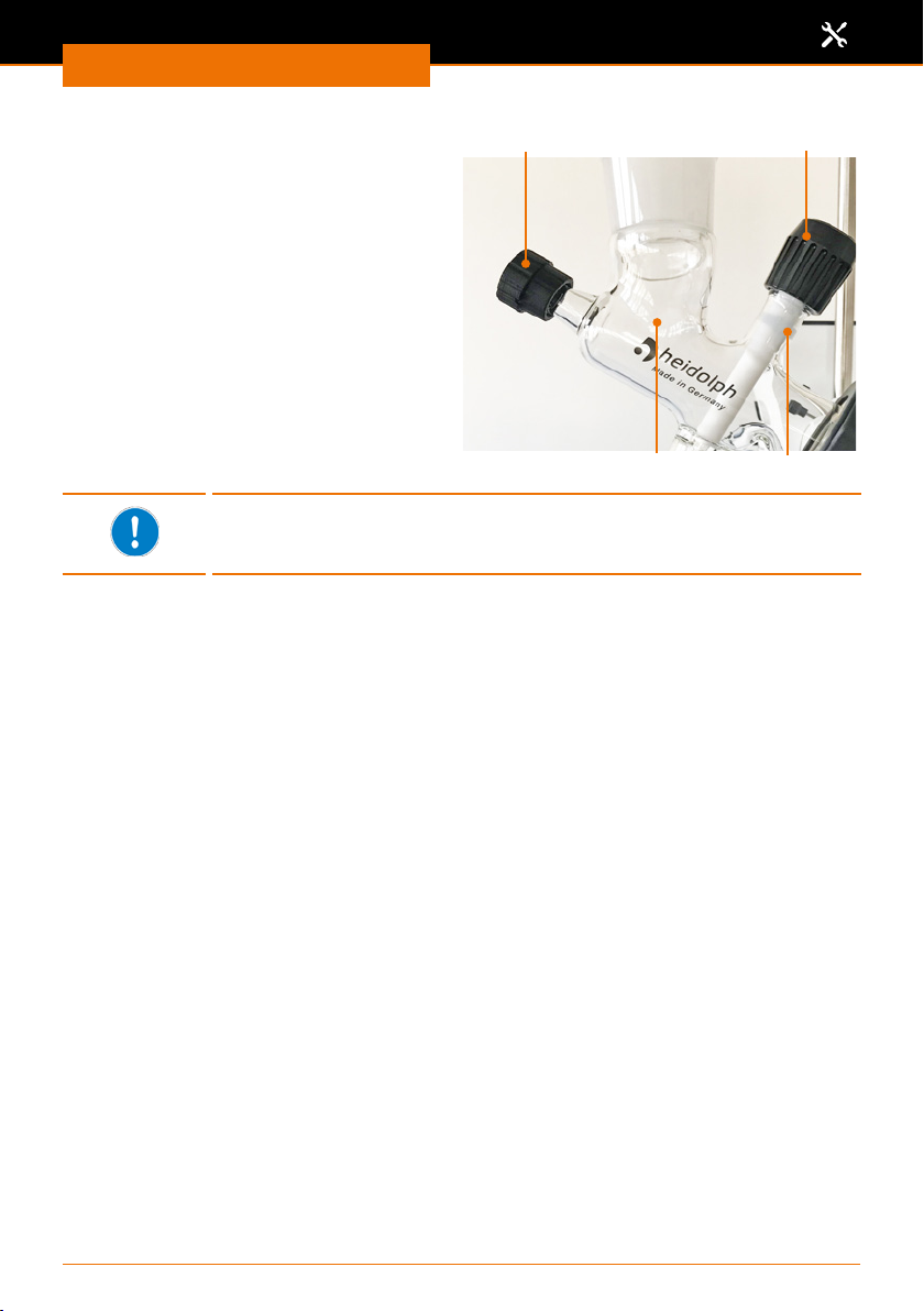
Assembly
➜ Turn reux valve clockwise until the
seal ring is clearly visible and white
plug blocks the output to the receiving
ask
✓ The valve is closed, and the sample is
guided back to the evaporating ask.
➜ Turn reux valve counterclockwise
until the white plug does not block the
outlet to the receiving ask.
✓ The valve is open, and the sample is
guided into the receiving ask.
The glassware set is no longer vacuum-tight if the reux valve is opened
too far. Open the valve only so far that the white seal ring underneath
the knurled screw remains visible about 0.5 cm wide.
Ventilation cap
Distributor
Reux valve
Seal ring
78
Page 79
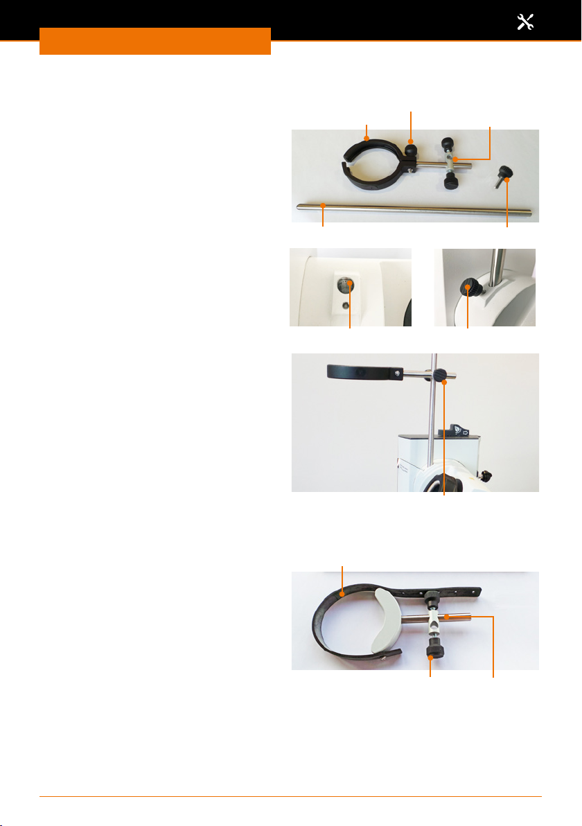
Assembly
Support system for vertical condenser: Glassware sets G1, G3, G3 XL and G6
Assembly parts:
▪ Support rod
▪ Cross clamp with condenser clamp
A hole is located on the left side of the
device for receiving the support rod.
✓ First mount the condenser and then
slide the condenser clamp over the
condenser.
➜ Insert the support rod with the
attened side downward into the hole.
➜ Secure the support rod with the
knurled screw.
➜ Slide the cross clamp over the support
rod.
➜ Use the knurled screw to secure the
cross clamp on the support rod.
➜ Secure the condenser clamp with the
knurled screw around the condenser.
Knurled screw for condenser clamp
Condenser clamp
Support rod
Knurled screw
Knurled screwDrilled hole
Cross clamp
Knurled screw for cross clamp
Support system for vertical condenser: Glassware set G5
Assembly parts:
▪ Support rod
▪ Cross clamp with tension strap
➜ Mount the support system like the
support for G3, G3 XL and G6.
➜ Use the tension strap to secure the
condenser.
Tension strap
Knurled screw
79
Cross clamp
Page 80
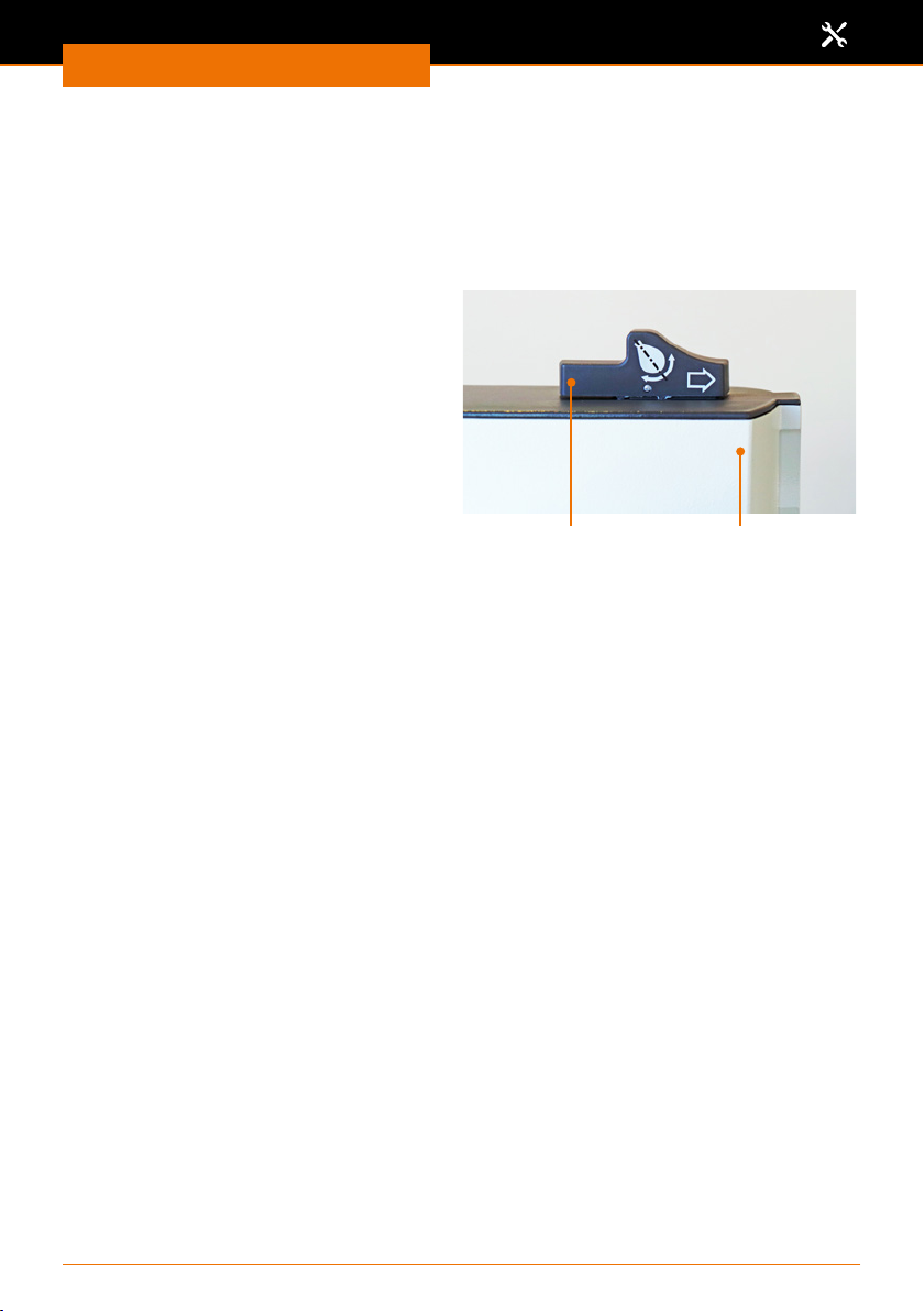
Assembly
Evaporating ask: Angle and immersion depth
Flask angle
The evaporating ask angle can be adjusted by turning the drive.
✓ The rotation is switched o.
✓ The evaporating ask is mounted (see chapter “Operation”, section “Mounting the
evaporating ask”).
➜ Slide the locking mechanism on lift
column to the right and hold it against
the spring force.
➜ Turn the condenser carefully until the
connected evaporating ask has the
correct angle. Ensure that the ask
can rotate freely and does not touch
anything.
➜ Release the locking mechanism.
➜ If necessary, turn the condenser
slightly until the drive unit locks in
place.
Lift columnLock
80
Page 81
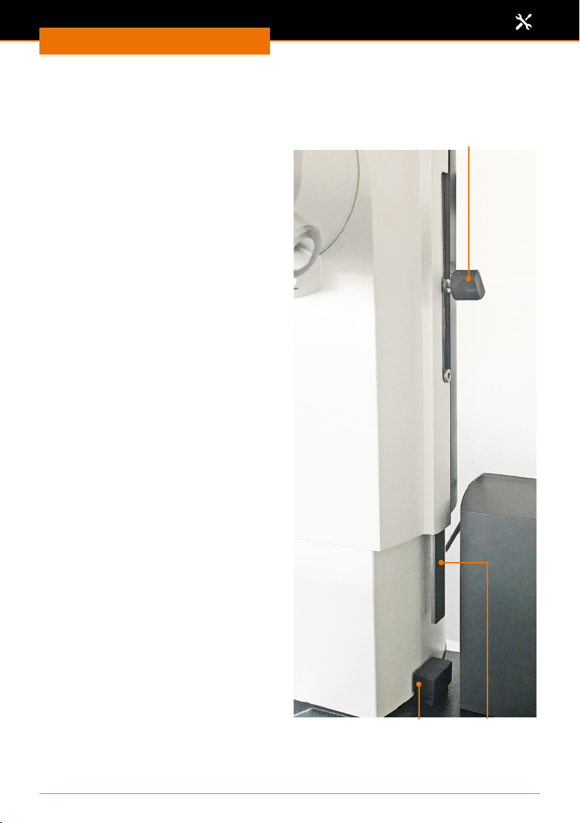
Assembly
Flask immersion depth (height stop)
The stop band of the height stop is located on the right side of the lift column that can be
used to adjust a constant immersion depth for the evaporating ask.
✓ The rotation is switched o.
✓ The evaporating ask is mounted (see
chapter “Operation”, section “Mounting
the evaporating ask”).
✓ The height stop is at the top position.
Adjusting the lift stop without the
safety hood:
➜ Lower the lift until the desired
immersion depth is reached (see
chapter “Start-Up”, section “Heating
bath and ask lift”).
➜ Turn the locking screw on the stop
band of the height stop to the right
of the lift column by about 180°
counterclockwise.
➜ Slide the stop band down as far as it
will go using the locking screw.
➜ Tighten the locking screw clockwise.
➜ Return the lift to the top.
✓ The locking screw holds the stop in
position.
✓ The lift moves down no further than
the stop and ensures a constant
immersion depth of the evaporating
ask
Adjusting the lift stop with the safety
hood:
➜ Hold the safety hood with one hand.
➜ Guide the safety hood by hand when
moving the safety hood
(see chapter “Assembly, Safety hood”).
Locking screw
Lift stop
81
Stop band
Page 82
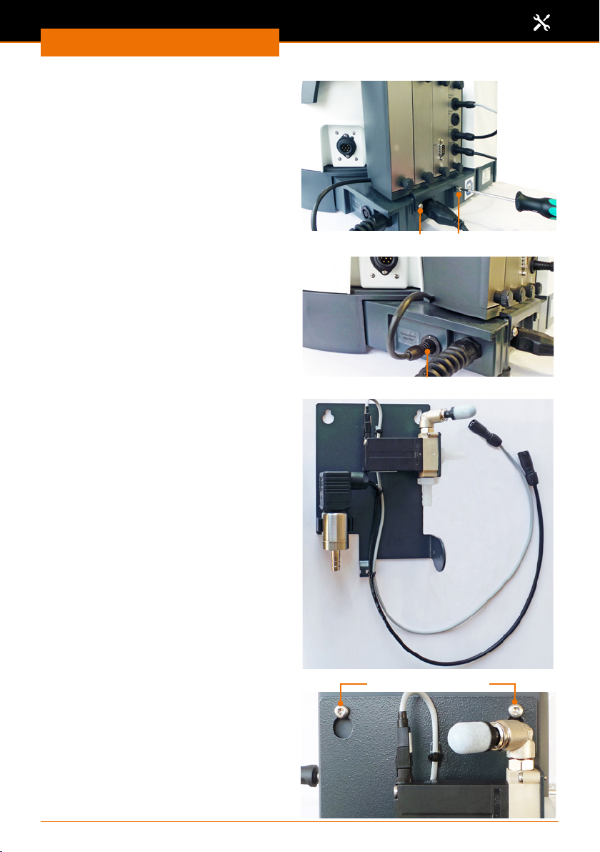
Assembly
Control box
The control box is mounted to the base
plate behind the heating bath.
➜ Attach the control box to the base
plate with the two included metric
screws.
The control box plug is on the rear of
the heating bath to the right, next to the
heating bath plug.
➜ Plug the cord of the control box into
the connection on the base plate.
Vacuum manifold
Assembly parts
▪ 1x vacuum manifold
(holding plate with vacuum sensor,
ventilation valve and dirt lter)
▪ 2x threaded screws
▪ 1x torx wrench
Fixing bolt
Control box connection
The sheet of the vacuum manifold is
mounted onto the back side of the ask
lift.
➜ Use the torx wrench to screw the two
threaded screws into the back side of
the ask lift by a few turns.
➜ Hang the sheet of the vacuum
manifold onto the two threaded
screws.
➜ Tighten the two screws.
✓ The vacuum manifold is installed.
Threaded screws
82
Page 83
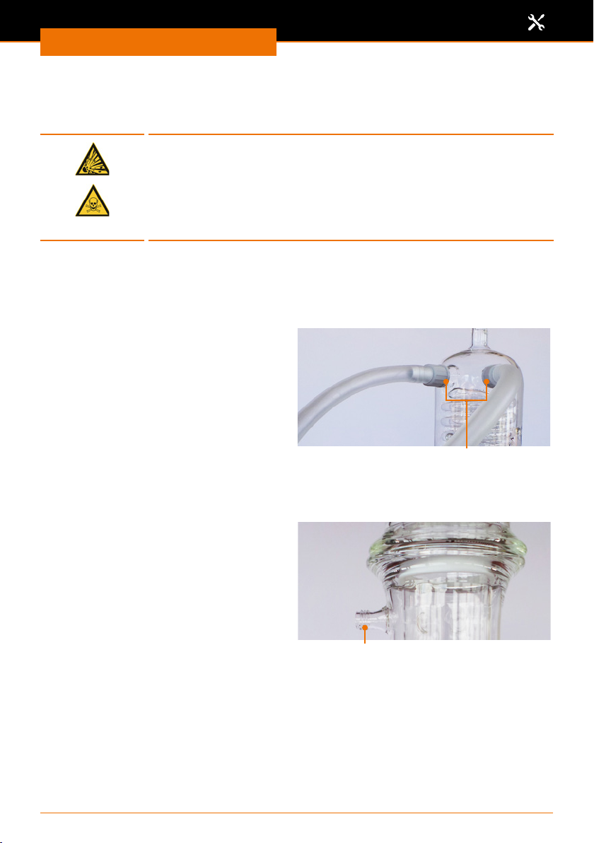
Assembly
Attaching the peripheral devices
Connecting vacuum
Warning:
Risk of implosion, risk of poisoning
Glass asks that show even the slightest damage can burst and,
depending on the sample, can poison the surrounding air.
Do not increase the vacuum pressure unless necessary.
Never exceed the permissible pressure of your distillate.
To connect the vacuum, you need:
▪ a vacuum source
▪ a vacuum tube (Ø 7-8 mm inside)
Glassware sets G1, G3, G3 XL and G6
The opening for the vacuum connection is located on the back and top of the
condenser.
➜ Unscrew a screw cap with the tube
nipple.
➜ Push the vacuum tube onto the tube
nipple.
➜ Tighten the screw cap with the tube
nipple and the tube.
➜ Attach the other end of the tube to the
ventilation valve on the back side of
the evaporator.
Glassware set G5
The opening for the vacuum connection is located on the back and top of the
condenser.
Vacuum connections G1, G3, G3 XL and G6
Vacuum connection screw caps
Vacuum connection G5
Vacuum connection opening
83
Page 84
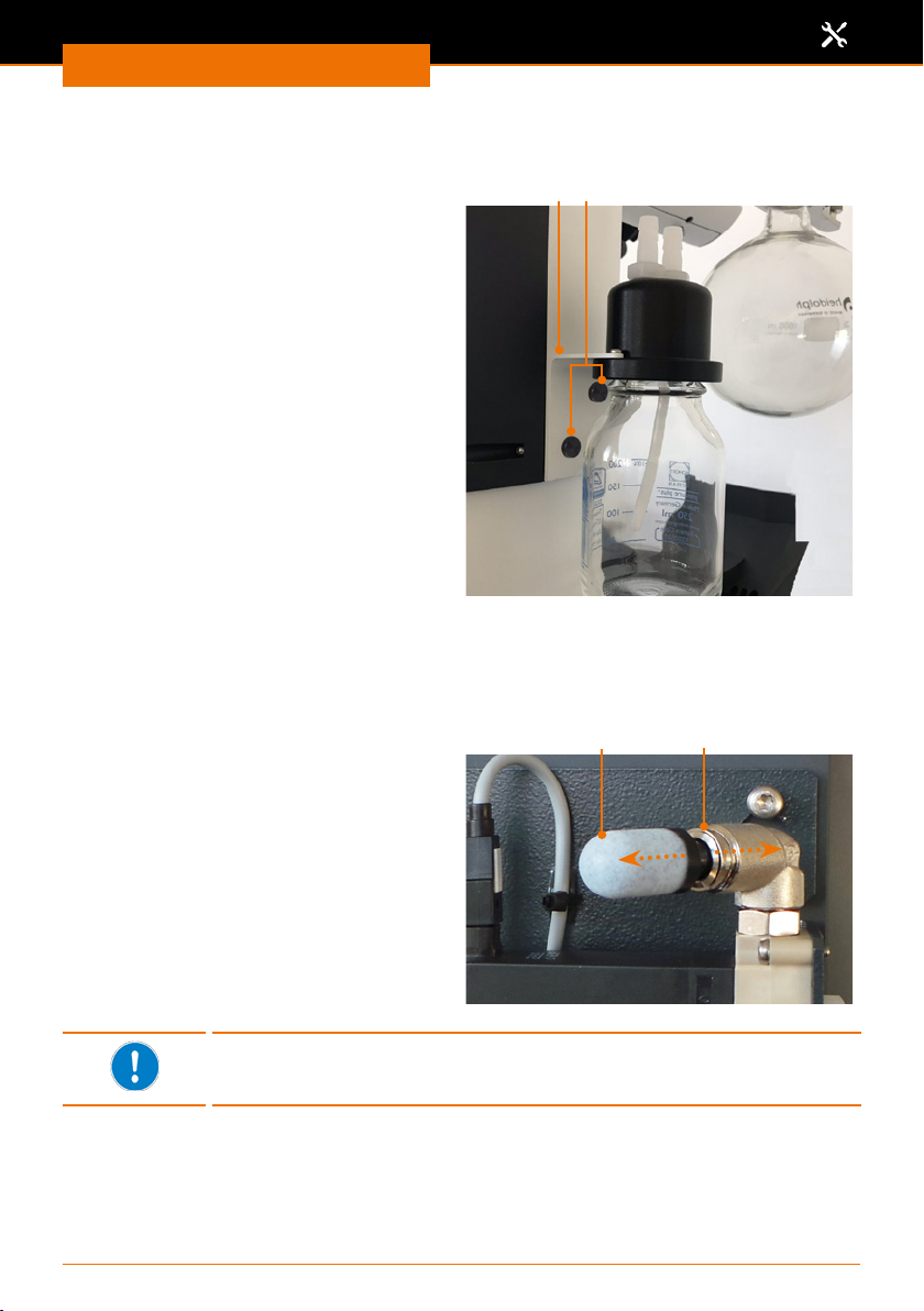
Assembly
Woulfe’s bottle
(optional accessories: see chapter “Spare Parts and Accessories”)
The Woulfe’s bottle is attached between
ventilation valve and condenser.
➜ Unscrew the glass bottle from the lid.
➜ Use the two included knurled screws to
x the retainer bracket to the side of
the ask lift.
➜ Hand-tighten the glass bottle on the
lid again.
➜ Lay a short tube from the ventilation
valve to the outlet of the Woulfe’s
bottle.
➜ Lay a slightly longer tube from the
inlet of the Woulfe’s bottle to the
opening for the vacuum connection on
the back side of the condenser at the
top.
Connecting inert gas
The inert gas connection is situated at the ventilation valve on the vacuum manifold.
Prior to connecting the inert gas, the dirt lter must be removed from the ventilation
valve.
Knurled screwsRetainer bracket
➜ Pull back the release ring around the
opening of the ventilation valve and
pull o the dirt lter.
➜ Now connect the inert gas.
➜ When removing the inert gas
connection, put the dirt lter back onto
the ventilation valve.
When the device has been in operation for some time, the ventilation
valve will get very hot. Before connecting the inert gas, switch o all
processes and let the ventilation valve cool down for a bit.
Release ringDirt lter
84
Page 85
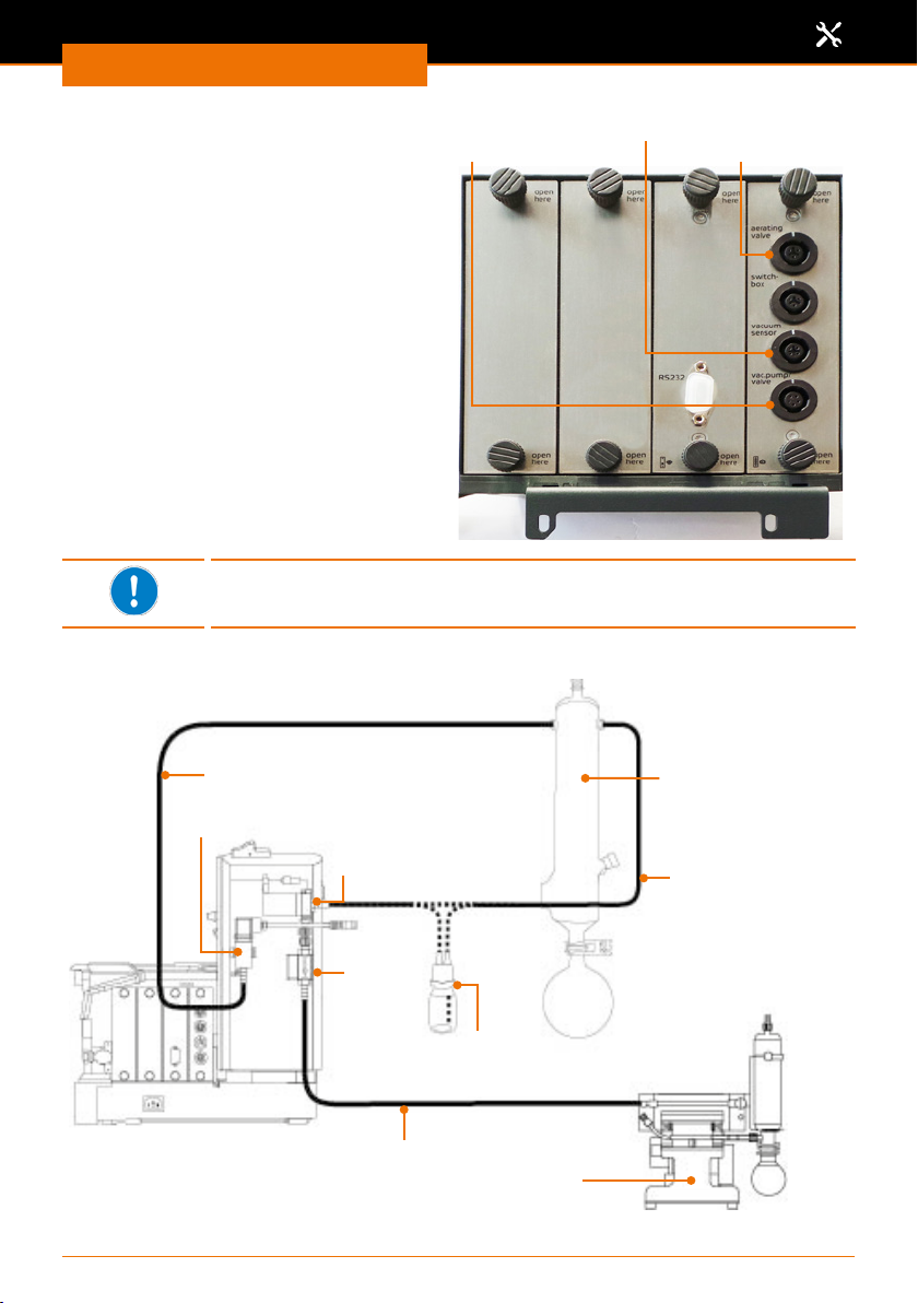
Assembly
Attaching the vacuum control to the
control box
Vacuum valve
Vacuum sensor
Ventilation valve
The components for the vacuum control
are situated on the vacuum manifold at the
back side of the ask lift. The connections
for these components are situated on the
control box.
➜ Attach the cable of the ventilation valve
to the connection “aerating valve”.
The ventilation valve is situated on the
top right of the vacuum manifold.
➜ Attach the cable of the vacuum sensor
to the
“vacuum sensor” connection.
Only for valve-controlled pumps:
➜ Attach the cable of the vacuum valve to
the connection
“vacuum valve”.
If you operate with a valve-controlled vacuum pump, you require the
vacuum valve. This is available as optional accessories (see chapter
“Spare Parts and Accessories”)
Connection diagram for vacuum: Example valve-controlled pump/house vacuum
(View: evaporator back side)
Tube:
Condenser -
Condenser
vacuum sensor
Vacuum sensor
Ventilation valve
Tube:
Ventilation valve condenser*
Vacuum
valve
optional:
Woulfe’s bottle connection
Tube: Pump vacuum valve
Pump, e.g. Rotavac pumping
station with condensate cooler
* The optionally available Woulfe’s bottle is attached between condenser and ventilation valve, if
required.
85
Page 86
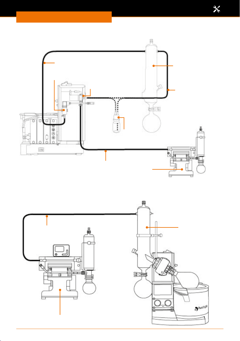
Assembly
Connection diagram for vacuum: Example speed-controlled pump
(View: evaporator back side)
Tube:
Condenser vacuum sensor
Vacuum sensor
Ventilation valve
optional:
Woulfe’s bottle connection
Tube: Pump vacuum valve
Pump, e.g. Rotavac pumping
station with condensate cooler
* The optionally available Woulfe’s bottle is attached between condenser and ventilation valve, if required.
Connection diagram for vacuum: Example pumping station with integrated
vacuum control
(View: evaporator front)
Condenser
Tube:
Ventilation valve condenser
Tube:
Pump - condenser
Vacuum pump with integrated controller,
e.g. Rotavac Vario pumping station
Condenser
86
Page 87
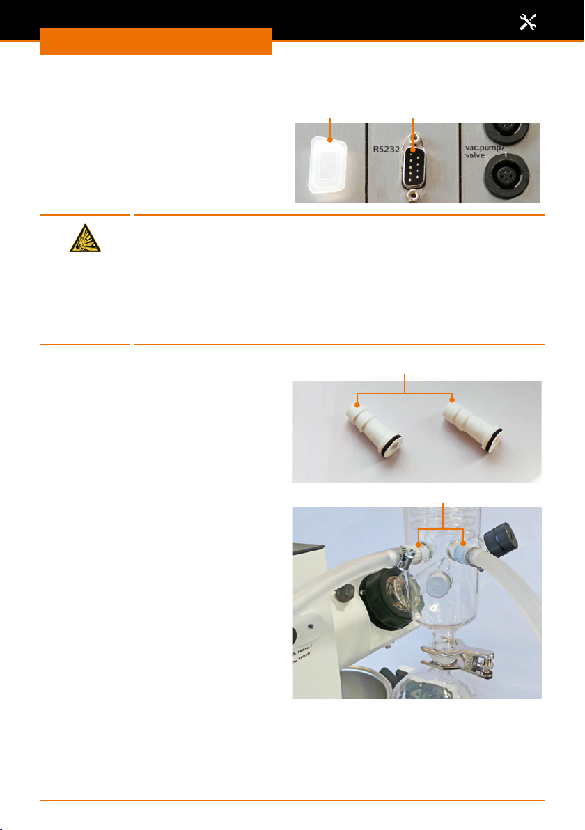
Assembly
Cooling water connection
The external chiller Hei-CHILL is attached
to the RS-232 interface on the back side
of the control box. The cooling temperature is then displayed in the control panel
and can be adjusted there.
Warning:
Risk of explosion
A closed valve in the return line will build up high pressure in the glass
coils of condensers and may result in glass bursting.
The cooling coils of the condenser may be subjected to a maximum
cooling water pressure of 2 bar. To prevent a higher pressure from
ever occurring, no valve or throttle must be installed in the cooling
water return line.
Assembly parts:
▪ 2x tube nipple
(included in scope of delivery)
▪ 2x tube clamps
(included in scope of delivery)
▪ 2x tube clamps
▪ 1x tube, inside Ø 7-8 mm
(included in the optionally available tube
set)
Cooling uid inlet and outlet are located
on the back and bottom of the condenser.
➜ Remove the screw caps from the
cooling water inlet and outlet.
➜ Push the screw caps over the tube
nipples so that the black seal is located
inside the cap.
➜ Push the respective feed and outlet
hoses for the cooling water through
the screw cap over a tube nipple.
➜ Tighten the screw caps with the seal
rst on one of the respective openings
of the condenser.
➜ Secure the tubes additionally with the
tube clamps included in the delivery.
✓ Cooling water feed and return line are
connected.
RS-232 interfaceSealing cap
Tube nipples
Cooling water inlet and outlet
87
Page 88
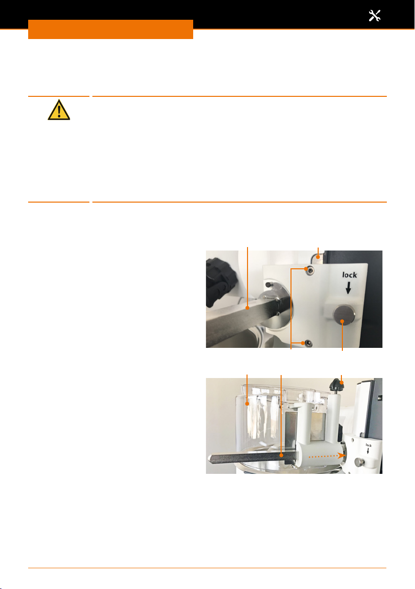
Assembly
Optional accessories
Safety hood
Caution:
Possible damage to the safety hood
If temperatures are too high and/or if the wrong heating bath uids are
used, the material will become soft and may be subject to deformations
and possibly tearing.
The safety hood is only suitable up to heating bath temperatures of
<130°C.
(For suitable heating bath uids see chapter “Start-up, Heating
bath and ask lift” as well as chapter “Spare Parts and Accessories,
Accessories”)
Before you can use the safety hood, you need to screw the support of the safety hood to
the height stop.
➜ If needed, slide the safety hood o the
carrier.
➜ Unscrew the locking screw from the
height stop band.
➜ Tighten the safety hood carrier on the
height stop band using the two supplied
Allen screws.
✓ The knurled screw on the safety hood
carrier takes over the function of the
locking screw for the height stop band.
Safety hood carrier Height stop
➜ Loosen the clamping screw and slide
the safety hood horizontally onto the
carrier until the hood sits above the
heating bath.
➜ Tighten the clamping screw.
✓ The safety hood is installed. The safety
hood can be lifted open at the handle
until it clicks into place.
Allen screws
Safety hood Carrier Clamping screw
88
Locking screw
Page 89
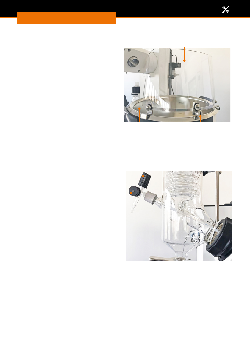
Assembly
Safety shield
➜ Move the ask lift upward
➜ Hang the safety shield to the edge of
the heating bath and position it so that
the (potentially present) safety hood
can be lifted open easily.
➜ Turn the eccentric screw 180° and
use to secure the safety shield on the
heating bath.
Inlet valve
(Optional accessories) Assembly parts:
▪ 2x inlet hose
▪ 1x inlet valve
During a running process, the sample ow
for the distillation is metered via the inlet
valve.
✓ The glassware set is under vacuum.
➜ Turn the inlet valve counterclockwise.
✓ The in-feed is opened, and the distillate
is drawn into the evaporating ask.
✓ The more you open the inlet valve, the
faster your sample will be supplied.
➜ Turn the inlet valve clockwise.
✓ The in-feed is reduced, or the inow of
the sample is stopped.
Safety shield
Heating bath Eccentric screw
Inlet valve
Ventilation cap
Mounting the inlet valve with the inlet hoses
All glassware sets (with the exception of glassware set G1) have a screw opening on the
lower left side of the condenser to accommodate the inlet hose with the inlet valve.
89
Page 90
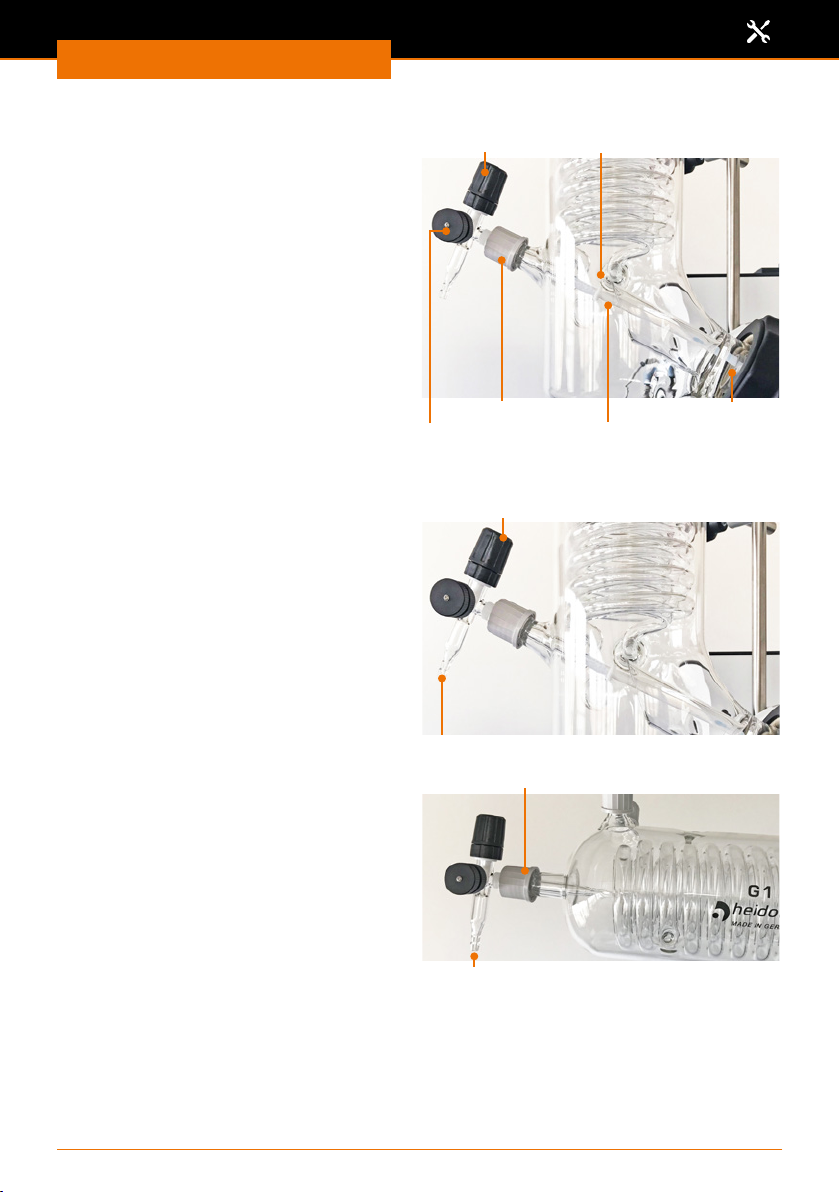
Assembly
Inlet hose 1
➜ Shorten the supplied PTFE tube so that
the end of the tube ends in the evapo-
rating ask.
➜ Slide the drain disk onto the PTFE tube
so that it is positioned before the vapor
tube of the evaporating ask.
✓ This prevents condensed uid from
owing back into the evaporating ask
via the inlet hose.
➜ Unscrew the screw cap from the
condenser.
➜ Slide the seal ring and screw cap about 3
cm onto the PTFE tube.
➜ Insert the inlet valve with the inlet hose into the inlet opening of the condenser and
tighten the screw cap.
Inlet hose 2
➜ Slide the PTFE tube onto the feed
opening.
✓ The inlet hoses are installed.
Inlet valve
Screw cap Vapor tube
Ventilation cap
Inlet valve
Drain disk
Inlet hose 1
Glassware set G1 inlet hoses
The opening for the inlet hoses is located at
the top of the condenser.
Opening for inlet hose 2
G1: Inlet hose screw cap 1
Opening for inlet hose 2
90
Page 91
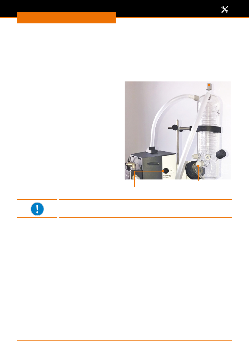
Assembly
Vapor temperature sensor, AUTOaccurate sensor
(optional accessory, see chapter “Spare Parts and Accessories”).
The opening for the vapor temperature sensor is located at the bottom on the side of the
condenser.
The opening for the AUTOaccurate sensor is located at the top center of the condenser.
➜ Remove the sealing cap from the
respective opening of the condenser.
➜ Insert the appropriate temperature
sensor.
The vapor temperature sensor is
inserted in the condenser from the side
whereas the AUTOaccurate sensor is
inserted from the top.
➜ Tighten the temperature sensor with
the screw connection cap.
➜ Plug in the connector plug of the
temperature sensor with the white
mark pointing upwards into the plug
socket on the left side of the device.
The AUTOaccurate sensor can only be used with glassware sets G3,
G3 XL and G6.
Opening for AUTOaccurate sensor
Opening for vapor temperature sensor
Temperature sensor connection
91
Page 92
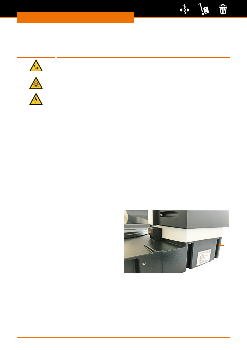
Dismantling and Storage
Dismantling, transportation and storage
Dismantling and Storage
Dismantling
Warning
Risk of scalding!
Hot glass surfaces and/or heating bath uids may result in scalding.
Allow all components to cool down before dismantling the device.
Risk of poisoning!
Leakage of hazardous substances and solvents at leak points can cause
hazardous substances to be released into the environment.
▪ Collect samples from the device in suitable containers.
▪ Before dismantling, ensure that no hazardous substances and
solvents adhere to the device components.
▪ If necessary, run a distillation process with harmless and solvent-free
samples before dismantling.
Risk of electric shock!
If the device is still connected to the power supply, you may come in
contact with electrically live parts when you dismantle the device.
Before dismantling the device, switch it o and disconnect the mains
plug from the socket. Do not reconnect the device to power under any
circumstances.
✓ The device is switched o.
✓ The heating bath is emptied and cleaned.
➜ Remove all tube and cable connections to cooling water, vacuum and other devices.
➜ Remove all glassware and remove the heating bath.
Motor lift version: Install the
transportation lock
✓ The device is switched o.
➜ Press and hold the lift stop on the ask
lift.
➜ Switch the device on and keep the lift
stop pressed until the device is fully
raised.
➜ Release the lift stop.
➜ Move the ask lift to the bottom
position.
Lift stop Transportation lock
✓ “Transportation lock activated” will appear in the control panel.
➜ Use the provided Allen key to attach the metal sheet of the transportation lock with
the 3 screws.
➜ Switch the device o.
➜ Disconnect the power cord from the socket and the device.
92
Page 93

Dismantling and Storage
Transportation and storage
➜ Only store and transport the device and its components after emptying and cleaning.
➜ Store and transport the device and its components in the original packaging or in
another suitable container to prevent any damage.
➜ Carefully seal the packaging against any unauthorized or unintentional opening.
➜ Store the device in a dry and frost-free location.
Improper handling during storage and transportation may result in
damage to the device and the mechanical components of the device.
Avoid jolts and vibrations when transporting the device.
93
Page 94

Spare Parts and Accessories
Scope of delivery
Component Quantity
Hei-VAP Expert: Motor lift device with glassware set G3* 1 574-01000-00
Hei-VAP Ultimate: Motor lift device with glassware set G3* 1 576-01000-00
Control box 1 569-00200-00
PTFE/FKM vacuum seal 1 23-30-01-01-30
Vapor tube 1 514-00000-01
Clamping sleeve 1 23-30-01-05-31
Motor lift transportation lock 1 11-300-006-28
Coupling 1 23-09-03-01-03
Tension spring 1 22-03-02-01-05
Easy Clip ask clamp, NS 29 1 23-30-01-05-29
Easy Clip ask clamp, NS 24 1 23-30-01-05-57
Ground joint clamp 1 515-42000-00
Operating manual German / English 1 01-005-005-86
Warranty registration / declaration of no objection 1 01-006-002-78
EU Declaration of Conformity 1 01-001-025-03
Power cord 1 country-dependent
* The indicated product numbers are valid for 230 V devices in the European Community. Please
contact our sales department or www.heidolph-instruments.com for product numbers of country-
specic varieties.
Spare parts and accessories
Product number
Accessories
Component Quantity
Device fuse, 230 V 2 14-002-028-22
Device fuse 115 V 2 14-002-028-29
Vapor temperature sensor 1 569-00030-00
AUTOaccurate sensor 1 569-00040-00
Safety hood 1 569-00010-00
Safety shield 1 569-00020-00
5 L Budde heating bath uid (20° C to 170°C) 1 515-31000-00
5 L Wacker AP 200 silicone oil (150° C to 210° C) 1 569-00600-00
Tube (suitable for vacuum and water) 1 591-35000-00
PTFE/FKM vacuum seal 1 23-30-01-06-70
Extension cord for control panel 1.5 m 1 14-300-020-12
Vacuum valve 1 14-300-005-28
Woulfe’s bottle 1 569-00071-00
Glassware sets see general catalog
Vacuum pumps and chillers
type and size vary
Product number
see general catalog
Additional accessories can be found in our general catalog or on our website at
www.heidolph-instruments.com
94
Page 95

Appendix
Software copyright
© Copyright 2018 - Copyright notice
The software contained in this product is protected by copyright.
The copyright is held by Heidolph Instruments GmbH & Co. KG, Walpersdorfer Strasse
12, 91126 Schwabach. Any Open Source software components which may be included
in the software are exempt. For details about the Open Source software included in
the product please see the supplementary sheet “Details about Open Source software
included in products” which is enclosed to the product as well as the respective information on the also enclosed data medium.
Copyright violations (e.g. the unauthorized use or alterations of the software) can prompt
claims according to civil law (such as omittance, compensation of damages, German
Copyright Act [UrhG] 97 et seqq.) and/or indictable consequences (UrhG 106 et seqq.).
95
Page 96
Service
Technical data
Appendix
Hei-VAP Core
Standard supply voltage 230 V 50/60 Hz or 115 V 50/60 Hz
Power consumption (W) 1400
Protection class (IEC 60529) ▪ Device: IP 20
▪ Heating bath cable: IP 67
▪ Control box: IP 42
▪ Control panel: IP 42
Noise pressure level (dB(A))
< 85 dB(A)
(based on IEC 61010)
Flask lift vertical travel (mm) 155
Motor EC motor
Rotation speed range (rpm) 10-280
Speed control electronic
Heating bath container
▪ Inner Ø: 253 mm, Ø outer: 291 mm
▪ Material: stainless steel (1.4404) X2CrNiMo 17-12-2
▪ Volume 4.5 l
Heating capacity (W) 1,300
Heating bath temperature range
(°C)
▪ 20-100 H
▪ 20-210 oil
O
2
Heating bath temperature control electronic
Heating bath control accuracy (°C) ±1
Excess temperature protection cut o at 5 °C dierence to set temperature
Overheating protection (°C) 250
2
Condensing area (cm
Evaporation rates (L/h)
ΔT* = 40°C (continuous operation)
) 1,400
▪ Toluene 8.5
▪ Acetone 5.8
▪ Ethanol 3.5
▪ Water 1.2
Digital displays ▪ Bath temperature display (°C)
▪ Vapor temperature display (°C)
(only with optional vapor temperature sensor)
▪ Rotation speed display
▪ Vacuum display
Lift operation Manual lift Motor lift
Weight (without glassware set and
14.7 15
control box) (kg)
Lifting speed (mm/s)
Dimensions with glassware set G3
- 25
739 x 532 x 887 739 x H 477 x 887
(w x d x h) (mm)
* ΔT = Dierence between bath temperature and vapor temperature
96
Page 97

Service
Contact / Technical Service
Questions and repair work
If any aspect of installation, operation or maintenance is not covered in this manual,
please get in touch with the following address.
For repairs, please call Heidolph Instruments directly or your local authorized Heidolph
Instruments distributor beforehand.
Warning:
Risk of poisoning!
Contaminated devices can lead to severe injury or death of our
employees!
When shipping devices for repair that may have been contaminated by
substances harmful to health, please:
▪ advise exact substance
▪ take adequate protective action towards our parts receiving and
service personnel
▪ mark the pack in accordance with Ordinance on Hazardous
Substances
A declaration of no objection can be found at the end of this operating manual.
➜ Prior to shipping the device for repair, complete a copy of this declaration of no
objection form and submit it in advance.
Our contact details for Germany, Austria, Switzerland
Service
Please only send devices to this address after prior consultation with
us:
Heidolph Instruments GmbH & Co. KG
Technical Service
Walpersdorfer Str. 12
91126 Schwabach/Germany
Phone: +49 9122 9920-74
Fax: +49 9122 9920-84
E-mail: [email protected]
Local distributors
You will nd the contact details of your local Heidolph distributor at
www.heidolph.com
97
Page 98

Service
Warranty
Heidolph Instruments provides a 3 year warranty for the
products described here (excluding glass and wearing parts) if
you register using the warranty card enclosed or online (www.
heidolph.com). The warranty period begins with the date
of purchase. The device serial number is also valid without
registration.
This warranty covers material and manufacturing defects.
In the event of a material or manufacturing defect, the device shall be repaired or
replaced free of charge under the terms of the warranty.
Heidolph Instruments shall not assume liability for any damage incurred as a result of
improper handling or transport.
➜ Please notify Heidolph Instruments if you wish to make a warranty claim.
98
Page 99
Service
Declaration of no objection
➜ In the case of repair, copy and complete the declaration of no objection form and
send it to Heidolph Instruments
1. Details about the device
Product number
Serial number
Reason for repair
2. Has the device been cleaned, decontaminated/sterilized?
Yes No
3.
Is the device in a condition which does not represent any health threats
for our service department sta?
Yes No
If not, which substances has the device
come into contact with?
4. Legally binding declaration
The customer is aware of being legally liable to Heidolph
Instruments for any damages arising from incomplete and
incorrect information.
Date Signature
Company stamp
Please note
The shipper is responsible for the return of the goods in well
packed condition, suitable for the mode of transport.
Sender information
Name, rst name
Company
Department, research
group
Street
Zip code, city
Country
Phone
E-mail
99
Page 100

Original-Betriebsanleitung
InhaltsverzeichnisInhaltsverzeichnis
Zu diesem Dokument 102
Version und Varianten ..................................................................................... 102
Über dieses Handbuch ..................................................................................... 102
Symbole und Signalwörter ............................................................................... 103
Inhaltsverzeichnis
Sicherheitshinweise 104
Allgemeine Sicherheitshinweise ........................................................................ 104
EU Konformitätserklärung ......................................................................... 104
Bestimmungsgemäße Verwendung ............................................................. 104
Installation / Elektrische Sicherheit ............................................................ 104
Qualikation der Mitarbeiter ...................................................................... 105
Pichten des Betreibers ................................................................................... 105
Aufstellort ............................................................................................... 105
Änderungen am Gerät .............................................................................. 106
Sicherheit des Personals ........................................................................... 106
Safety during use ........................................................................................... 106
Disposal ........................................................................................................ 107
Gerätebeschreibung 108
Geräteübersicht.............................................................................................. 108
Gesamtansicht: Hei-VAP Expert, Hei-VAP Expert Control ............................... 108
Gesamtansicht: Hei-VAP Ultimate, Hei-VAP Ultimate Control .......................... 109
Control-Box (nur bei Control Varianten) ...................................................... 111
Bedienfeld: Hei-VAP Expert, Hei-VAP Expert Control ..................................... 111
Bedienfeld: Hei-VAP Ultimate, Hei-VAP Ultimate Control ................................ 112
Inbetriebnahme 113
Gerät aufstellen ............................................................................................. 113
Netzkabel anschließen / lösen .......................................................................... 113
Transportsicherung entfernen ........................................................................... 113
Gerät ein- und ausschalten .............................................................................. 114
Heizbad und Kolbenlift .....................................................................................114
Grundeinstellungen ......................................................................................... 117
Menüführung ................................................................................................. 119
Übersicht Menüstruktur ............................................................................ 119
Bedienung des Menü ................................................................................ 121
Grundeinstellungen ändern .............................................................................. 124
Sprache und Formate ............................................................................... 124
Datum und Uhrzeit .................................................................................. 124
Einstellungen .......................................................................................... 125
Anwendungen ......................................................................................... 128
Verwendete Symbole ......................................................................................129
Bedienung 133
Prozessablauf ................................................................................................. 133
Anwendung auswählen ............................................................................. 133
Prozesszeiten protokollieren ...................................................................... 135
Anwendungen ................................................................................................ 136
Parameter manuell einstellen („Anwendung Basis”) ......................................136
Favoriten verwenden und verwalten (Anwendung „Erweitert”) ........................ 140
Rampenprole verwenden und verwalten (Anwendung „Erweitert”) ................144
 Loading...