

Page 1
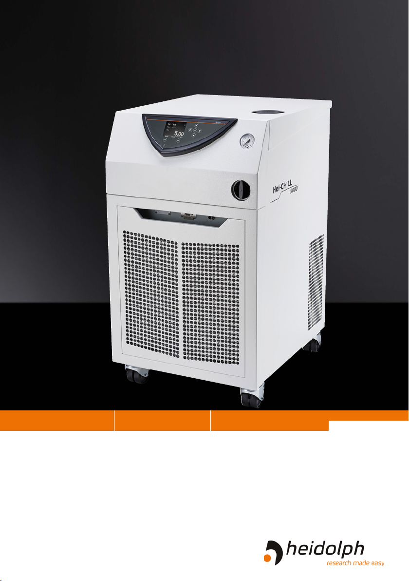
Hei-CHILL
Chiller
Leading Safety Standards Superior Ease of Use Reduced Cost of Ownership
Operating Manual Page 2
Circulation chiller Hei-CHILL 3000, Hei-CHILL 5000
Operating manual must be read before initial start-up.
Please follow the safety instructions provided.
Please keep for future reference.
Original-Betriebsanleitung Seite 34
Umlaufkühler Hei-CHILL 3000, Hei-CHILL 5000
Betriebsanleitung vor Erstinbetriebnahme unbedingt lesen.
Sicherheits hinweise beachten.
Für künftige Verwendung aufbewahren.
Page 2

Operating Manual
Contents
About this Document 4
Version and variants ...........................................................................................4
About this manual ..............................................................................................4
Symbols and signal words ....................................................................................5
Inhaltsverzeichnis
Safety Instructions 6
General safety instructions...................................................................................6
EU Declaration of Conformity .........................................................................6
Intended use...............................................................................................6
Installation .................................................................................................7
Qualications of personnel ............................................................................7
Operating company’s obligations ...........................................................................8
Installation site ...........................................................................................8
Modications to the device ............................................................................8
Safety of personnel ......................................................................................8
Safety during use ...............................................................................................9
Disposal ............................................................................................................9
Device Description 10
Device overview ...............................................................................................10
Device overview Hei CHILL 3000, Hei CHILL 5000 ..........................................10
Hei CHILL control panel ..............................................................................10
Start-Up 11
Setting up the device ........................................................................................11
Connecting/disconnecting the power cord ............................................................12
Switching the device on and o ..........................................................................12
Selecting the language ......................................................................................13
Filling with thermal uid ....................................................................................14
Menu navigation ...............................................................................................16
Presettings ......................................................................................................18
Selecting the language ...............................................................................18
Setting the temperature limit ......................................................................18
Setting the temperature setpoint .................................................................19
Setting the date and time ...........................................................................20
Operation 21
Menu structure Overview ...................................................................................21
Temperature control operation ............................................................................23
Adjusting the pump pressure .......................................................................24
Special functions ..............................................................................................24
Standby operation and autostart ..................................................................24
Setting the operating mode for the cooling unit..............................................25
Setting the setpoint oset ...........................................................................26
Adjusting the basic settings ...............................................................................27
Page 3

Contents
Control parameters ...........................................................................................29
Temperature control via programs ......................................................................31
Preparing a program ..................................................................................31
Specifying program runs .............................................................................32
Starting and ending a program ....................................................................33
Device status ...................................................................................................34
Interfaces ........................................................................................................35
Connecting the alarm output .......................................................................36
Restoring the factory settings .............................................................................37
Cleaning and Maintenance 38
Cleaning ..........................................................................................................38
Cleaning the device ....................................................................................38
Maintenance ....................................................................................................39
Maintenance .............................................................................................39
Troubleshooting 41
Malfunctions and troubleshooting ........................................................................41
Assembly 46
Electrical connections ........................................................................................46
Peripheral connections ......................................................................................47
Overview of connections .............................................................................47
Temperature control hoses ..........................................................................48
Connecting the chiller to an external consumer ..............................................49
Calibrating the temperature sensor ..............................................................50
Disassembly and Storage 51
Dismantling, transportation and storage ..............................................................51
Emptying the device ..................................................................................51
Transportation and storage .........................................................................51
Accessories and Spare Parts 52
Scope of delivery ..............................................................................................52
Accessories ......................................................................................................52
Attachments 53
Technical data ..................................................................................................53
Performance range .....................................................................................54
Thermal uids ...........................................................................................55
Cooling unit ..............................................................................................56
Service 57
Contact / Technical Service ................................................................................57
Warranty .........................................................................................................58
Conrmation of condition ...................................................................................59
Page 4
About this Document
Copyright
This operating manual is protected by copyright and is exclusively intended for the
internal use of the purchaser.
Handing over this operating manual to third parties, reproducing it in any type or form
–in part or in full – and utilizing and/or communicating its contents is prohibited without
prior written approval from the manufacturer.
Any violations will result in an obligation to provide compensation for damages. Other
claims remain unaected.
About this Document
Version and variants
Version
This manual describes the function, operation and maintenance of the Hei-TORQUE Core
laboratory stirrer.
Version Alteration date
1.0 07/2018
Variants
The device is available in dierent variants. Certain features or functions are only available in specic product variants. These variants are described in this operating manual.
About this manual
This operating manual is an integral part of the device described here.
➜ Carefully read through this operating manual and observe all of the
safety instructions and warnings notices.
➜ Ensure that every user has carefully read the operating manual
before using the device for the rst time.
➜ Store this operating manual so that it is accessible to all users at
all times.
➜ Pass the operating manual on to any subsequent owner.
The current version of this operating manual can also be found at:
https://heidolph-instruments.com/en/service/downloads/opera-
tion-manuals/Magnetic Stirrers/All MR Hei- models/MR Hei-Standard,
MR Hei-Tec, MR Hei-Connect
In addition, also observe the local regulations at the installation site.
4
Page 5
About this Document
Symbols and keywords
Standardized symbols and signal words are used in this operating manual to warn against
any dangers and provide important instructions. These instructions must be strictly
observed to avoid accidents and damage.
The following terms and basic symbols are used:
Symbol Additional signal words / explanation
Warning
signs
Prohibitory
signs
Mandatory
signs
Other symbols used:
Symbol Description
➜
✓
▪
The yellow triangle indicates hazardous situations. It is used in combination with the following signal words:
DANGER:
Indicates a hazardous situation which, if not avoided, will result in
serious injury or death.
WARNING:
Indicates a hazardous situation which, if not avoided, may result in
serious injury or death.
CAUTION:
Indicates a hazardous situation which, if not avoided, may result in
property damage and minor or moderate injury.
Prohibited:
The red circle indicates a situation that should be avoided under all
circumstances and which, if not avoided, may result in serious injury
or death.
Must be observed:
The blue circle indicates important information. Please observe this
information to avoid any property damage.
Handling instruction, action required
Result of action
List of information
▪
▪
a.
b.
c.
List of variants
5
Page 6
Safety Instructions
General safety instructions
Safety Instructions
EU Declaration of Conformity
This device complies with the following EC-Directives*:
▪ 2006/42/EC Machinery Directive
▪ 2014/30/EU Electromagnetic Compatibility Directive
*Also see the attachment “EU Declaration of Conformity”.
The device has been manufactured according to state-of-the-art technology and in
compliance with recognized safety regulations. However, risks may still arise during
installation, operation and maintenance.
➜ Please ensure that the operating manual is available at all times.
The device may only be used under the following conditions:
➜ Only operate the device if it is in a technically perfect condition.
➜ Only operate the device if you are properly aware of the risks and required safety
measures.
➜ Only operate the device in accordance with the instructions given in this operating
manual.
➜ If any information is ambiguous or missing, ask your superior or contact the manufacturer.
➜ Do not operate anything on the device without authorization.
➜ Only use the device in accordance with its intended use.
Intended use
The device is intended for use by trained and authorized personnel only.
The device is suitable for
the following uses:
The device may be
operated in research
laboratories, other labora-
tories and production
facilities in the following
sectors:
▪ Cooling of rotary evaporators: Hei-VAP Industrial
▪ Tempering and delivering non-combustible heat transfer
liquids in a closed circuit
▪ Economical cooling as alternative to tap water systems
▪ Chemistry
▪ Pharmacy
▪ Biology
▪ Environmental analytics
▪ Basic research
▪ Similar research laboratories
Foreseeable misuse
Any use that deviates from the device‘s intended use is considered to be improper. The
manufacturer is not liable for damage that occurs as a result. The risk is borne by the
operator alone.
Among other things, the following uses are considered to be foreseeable misuse:
▪ Operation of the device without heat transfer liquid
▪ Incorrect connection of tubes
▪ Placement of the device on a tabletop surface
▪ Setting an incorrect pump pressure
▪ Operation of the device with a glass reactor without overpressure protection
▪ Chilling foodstus
6
Page 7

Safety Instructions
Installation
Electrical safety
▪ The device may only be connected up if the available power supply voltage corre-
sponds to the information stated on the rating plate for the device.
▪ The power supply connection must be easily accessibly at all times.
▪ An RCD circuit breaker (residual current circuit breaker) must be tted to the
electrical system in the building so that the device is disconnected from the power
circuit in the event of a fault.
▪ Repairs may only be performed by electricians authorised by Heidolph Instruments.
▪ Never operate the device with a damaged power cord.
▪ Always turn the device OFF and disconnect the power cord before carrying out any
maintenance or repair work.
Thermal uids
▪ The device is exclusively designed for nonammable thermal uids in Class I
according to DIN 12876-1.
▪ Each thermal uid covers a specic temperature range. This temperature range must
match the temperature range of your application. If these temperatures are exceeded
or undercut, serious hazards to health or environment can be caused (also see
chapter “Attachment, Technical data”, section “Thermal uids”).
▪ We recommend the use of Heidolph thermal uid. This has been tested and approved
by Heidolph Instruments.
▪ The safety data sheet must be consulted for the intended use of the device.
Tubes
▪ Besides material durability please note, that permissible temperature range and
maximum pressure must match with your application when selecting tubes for
connecting your periphery devices.
▪ We recommend the use of Heidolph tubes. These have been tested and approved by
Heidolph Instruments.
Qualications of personnel
▪ The device may only be operated by trained personnel.
▪ The device may only be operated by persons who have been instructed and super-
vised in its proper use by trained specialist personnel.
▪ The device may only be operated by specialist personnel who are above the legal
minimum age.
▪ Other persons may only work on the device under the constant supervision of experi-
enced and trained specialist personnel.
▪ This operating manual must be read and understood by all persons working with the
device.
▪ Personnel must receive safety training that ensures responsible and safe working
practices.
7
Page 8
Safety Instructions
Operating company’s obligations
Installation site
▪ The device must be installed in a suitable location.
▪ The device must be installed on a rm and stable surface.
▪ Ensure that the device and all of its components and connections are easily accessible
at all times.
▪ All vents of the device must have a minimum distance of 50 cm (20 inches) to walls
or vertical surfaces, so air ow is not restricted.
▪ It is not permitted to place or store any objects such as accessories, tools or
chemicals within this clearance area during operation.
▪ All screw connections must be securely tightened.
▪ It is not permitted to operate the device near highly ammable or explosive substances.
▪ Only operate the device (depending on the substances being used) in conjunction
with an extractor hood (see DIN EN 14175 and DIN 12924).
▪ The device is designed for indoor use only and under the following ambient condi-
tions:
Ambient temperature 5 - 31 °C at 80 % relative humidity
32 - 40 °C decreasing linearly to a
maximum 50 % relative humidity
Installation altitude 0 - 2,000 m above sea level
Contamination level 2
Overvoltage category II
Permissible supply
deviations
▪ If the device is operated in corrosive atmospheres, the service life of the device will
decrease based on the concentration, duration and frequency of the exposure to the
corrosive atmosphere e.g. concentrated hydrochloric acid (HCl).
± 10 %
Modications to the device
▪ It is not permitted to make any unauthorised modications or changes to the device.
▪ Do not attach or install any parts that have not been approved by the manufacturer.
▪ Unauthorized modications or changes will void the EC Declaration of Conformity for
the device and operation of the device will no longer be permitted.
▪ The manufacturer is not liable for any damage, dangers or injuries that result from
unauthorized modications and changes or due to the non-observance of the instructions in this manual.
Safety of personnel
➜ Ensure that the device is only operated by qualied specialist personnel and trained
employees.
➜ Observe the following instructions to avoid any personal injuries and property damage:
- Laboratory regulations
- Accident prevention regulations
- Hazardous Substance Act
- Other generally accepted occupational health and safety regulations
- Local regulations
8
Page 9
Safety Instructions
Safety during use
➜ Wear the appropriate clothing when working on the device (protective clothing,
protective glasses and, if necessary, safety gloves).
➜ Do not use the device in potentially explosive areas. The device is not protected
against explosion. There is no explosion or ATEX protection available.
➜ Do not carry out work with naked ames in the vicinity of the device (risk of
explosion).
➜ Do not operate or assemble devices in the vicinity which are emission or radiation
sources (electromagnetic waves) for the frequency range (3*10
➜ Do not operate or assemble appliances in the vicinity of the device which constitute
emission or radiation sources for ionizing radiation or in the ultrasonic range.
➜ Do not operate the device where adiabatic compression or shock waves might occur
(shock wave combustion).
➜ Attach all tube connections securely to ensure safe operation.
➜ Connect all cables and tubes without kinks and locate them outside the operating and
danger zone.
➜ Do not spill liquids over the device or any parts of it.
➜ Remove any accidentally spilled liquids immediately.
➜ Eliminate errors immediately.
➜ Avoid putting pressure on the display when you are not operating the device.
➜ Do not use abrasive material to clean the surface. Only wipe with damp cloth.
➜ Always switch the device OFF after use.
11
Hz to 3*1015 Hz).
Disposal
Refrigerant
➜ The device may only be disposed of by a qualied refriger-
ation technician.
➜ Dispose of the refrigerant in accordance with EC Directive
215/2067 in combination with 517/2014/EC.
(Type and quantity of the refrigerant can be seen on the
rating plate; also see chapter “Attachment, Technical data”,
section “Cooling unit”.)
Device and packaging
➜ Check the device components for hazardous substances and
solvents.
➜ Clean all components before disposal.
➜ Dispose of the device in accordance with the relevant
national regulations.
➜ Dispose of the packaging material in accordance with the
appropriate national regulations.
9
Page 10
Device Description
Device overview
Device Description
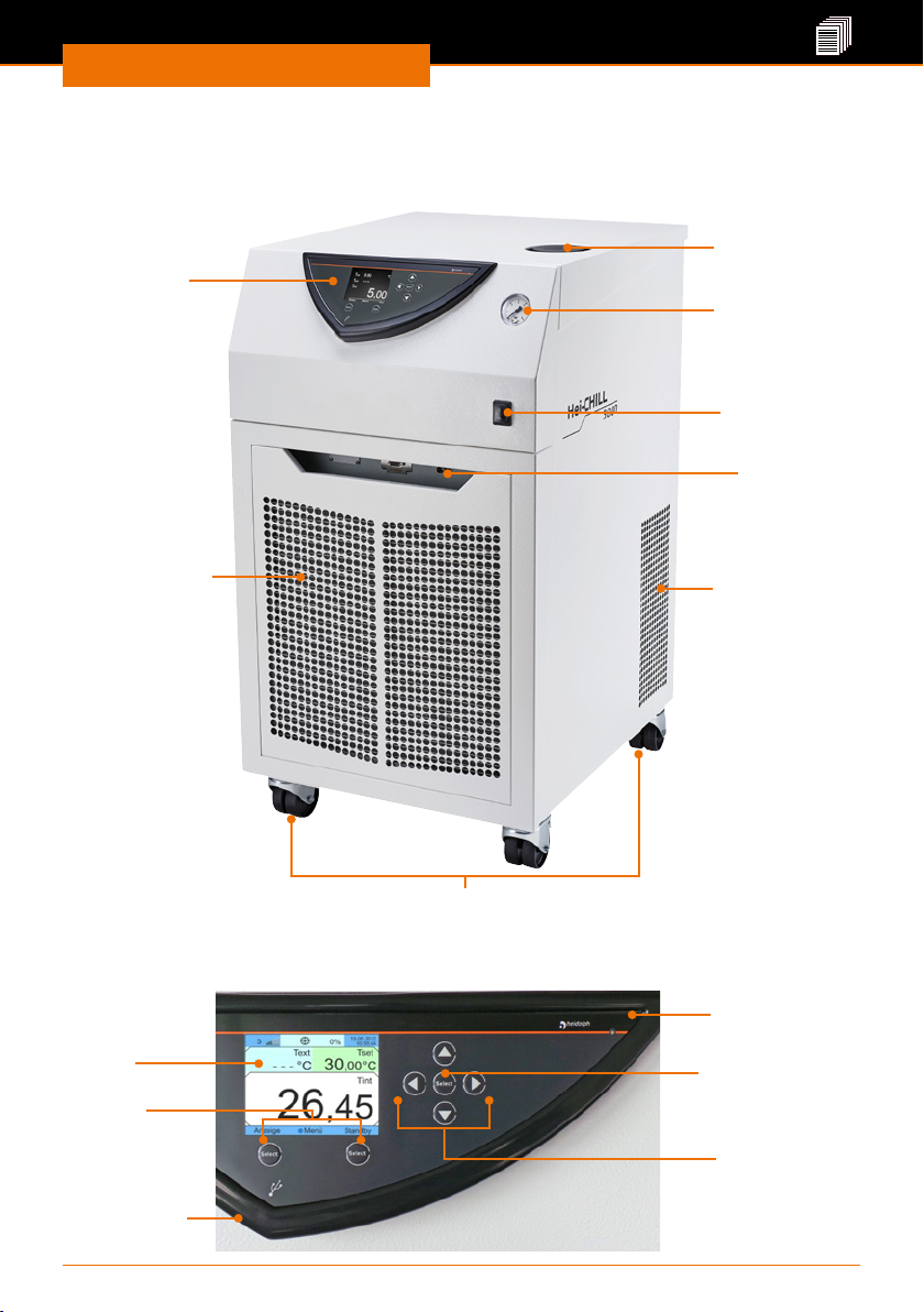
Device overview Hei CHILL 3000, Hei CHILL 5000
Filling pipe with
Control panel
Pressure gauge
ON/OFF switch
alarm output
Front cover with
ventilation grille
Ventilation grille
cover
Interface
4 castors, in front with parking brake
Hei CHILL control panel
Display
Softkeys:
Controlling
displayed
functions
USB interface
Photo sensor:
Controls display
brightness
button “Select”:
Conrming display
selection
Arrow buttons:
Navigating in the
display
10
Page 11
Start-Up
Setting up the device
Danger: Risk of poisoning!
Toxic vapours may be emitted depending on the thermal uid being
used and the type of operation.
Ensure that these vapours are extracted adequately.
Warning: Danger crushing!
The chillers are equipped with castors for easier mobility. This allows
the device to roll away and possibly tip over.
The devices may only be set up on the oor.Set up the device on a
level, non-slip surface with sucient load-bearing capacity!Secure the
device against rolling away by applying the locking brake!
Caution:
Possible damage to the cooling system
The liquid from the compressor may leak into the circulation system for
the thermal uid if the device is not set up in an upright position.
The device must not be tilted. Only set up, move and operate the
device in an upright position.
Caution:
Device damage
The device may overheat in the event of insucient airow.
Maintain a minimum distance of 50 cm between the ventilation grille
and walls or other vertical surfaces.
▪ The chiller can be set up lower than the apparatus to be cooled. When
relling the thermal uid, the pump must be switched on in this case,
and all hose connections must be checked for leaks, otherwise the
thermal uid can leak or overow.
▪ You can position multiple devices next to one another.
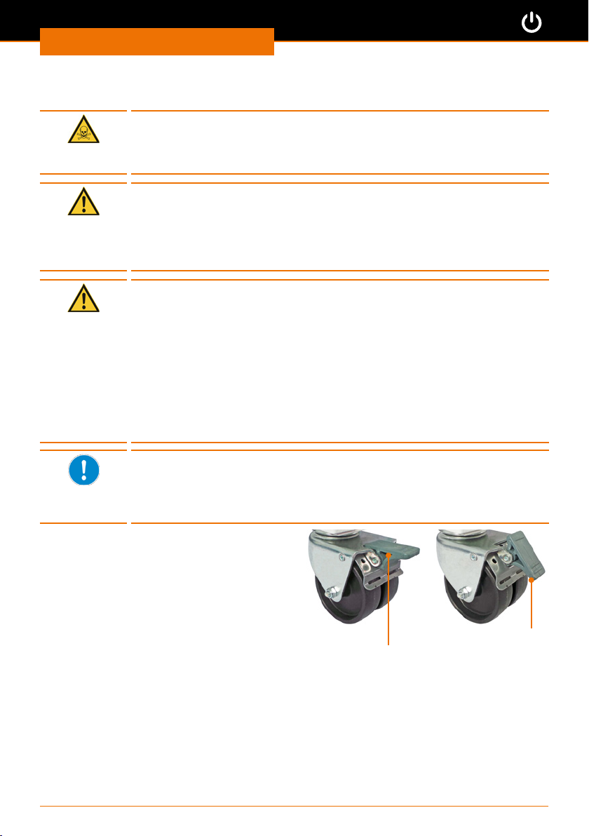
➜ Set up the device on a solid, smooth,
level and temperature-resistant surface.
➜ Release the locking brake on the castors
by pressing the lever upward.
➜ Lock the castors of the device by pressing
the lever downwards.
Start-Up
Locking brake
released
➜ Do not place heavy objects on the device.
➜ Clean the installation surface and the castors on the device at regular intervals.
11
Locking brake
applied
Page 12
Start-Up
Connecting/disconnecting the power cord
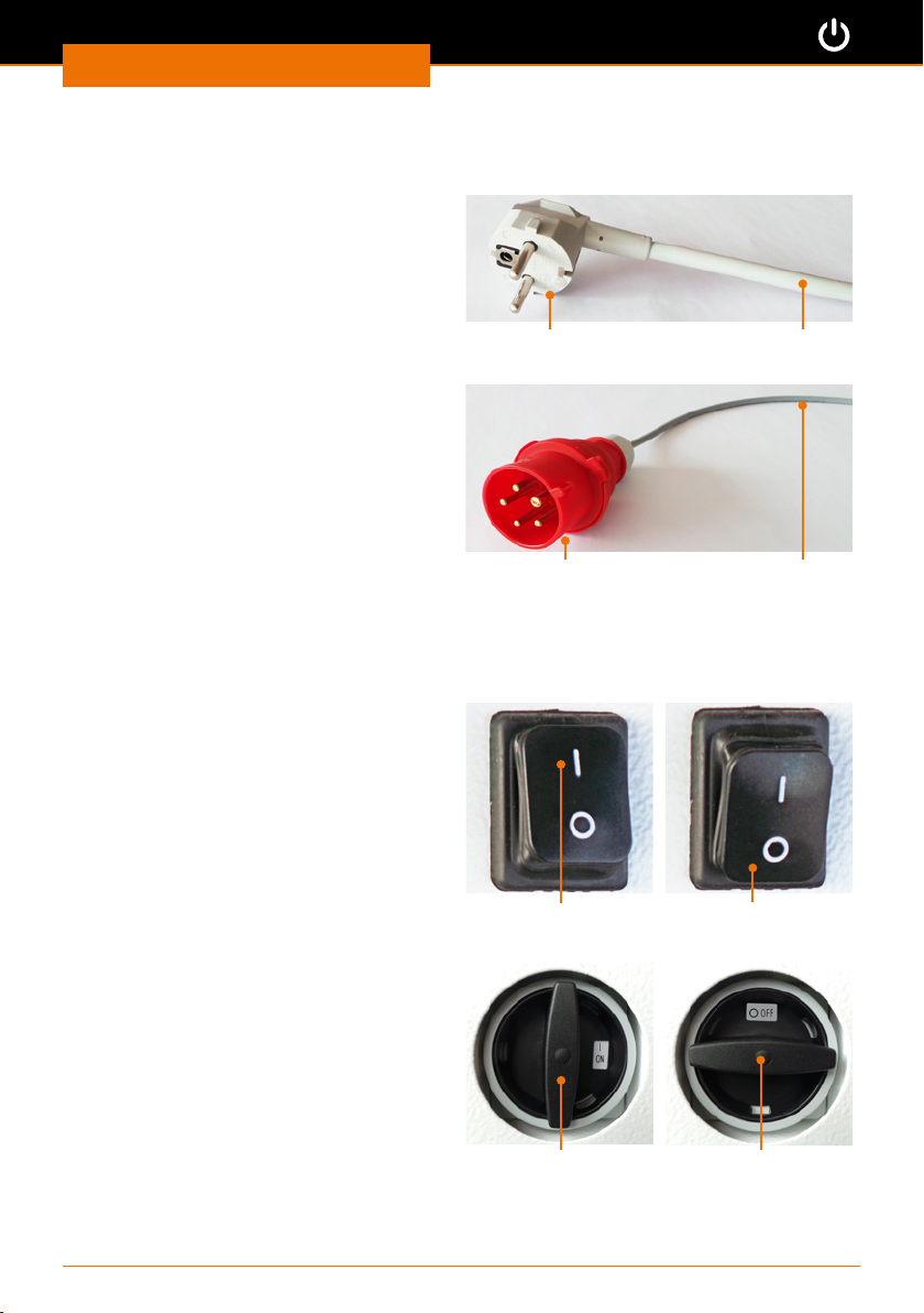
The power cord is permanently connected
to the device.
The connection is located on the rear of
the device.
✓ The main switch is switched OFF
(“power o” position).
➜ Connect the device connector to your
earthed socket.
✓ The connector is securely inserted
when it is pushed in to the stop.
➜ Disconnect the device connector when
the device is not operated.
Device connector
Hei-CHILL 3000
Hei-CHILL 5000
Switching the device on and o
Hei-CHILL 3000
Switching the device on
➜ Press the ON/OFF switch upward to “I”.
✓ The device is switched on.
Switching the device o
➜ Press the ON/OFF switch downward to
“O”.
✓ The device is switched o.
Hei-CHILL 5000
Switching the device on
➜ Rotate the ON/OFF switch clockwise
to “I”.
✓ The device is switched on.
Switching the device o
➜ Rotate the ON/OFF switch
anticlockwise to “O”.
✓ The device is switched o.
On/O switch: ON
On/O switch: ON
Hei-CHILL 3000
Hei-CHILL 5000
Power cord
Power cordDevice connector
On/O switch: O
On/O switch: O
12
Page 13
Start-Up
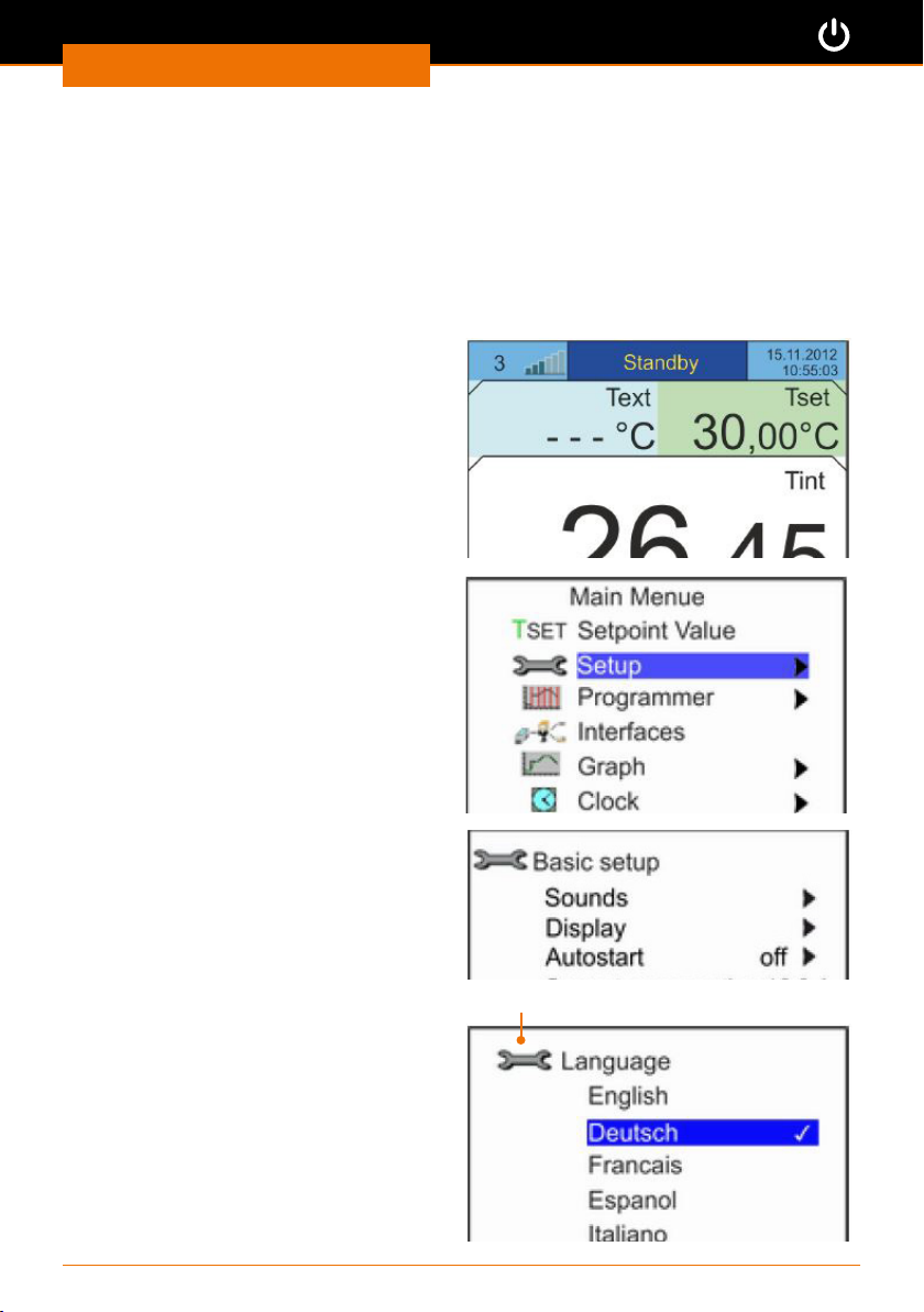
Selecting the language
➜ Switch the device ON.
✓ A signal tone sounds.
✓ The "Fill mode" submenu is automatically called up when the device is switched on for
the rst time.
✓ If the "Fill mode" submenu is not displayed in a language that you can understand,
the correct language must be selected rst.
➜ Press the "ESC" softkey.
✓ The base menu will be displayed.
➜ Press the “Select” button.
✓ The main menu will be displayed.
➜ Press the down
select the “Setup” menu.
➜ Conrm the selection using the
“Select” button.
✓ The “Setup” menu will be displayed.
➜ Press the down
select the “Basic Setup” menu.
arrow button to
ˇ
arrow button to
ˇ
Base menu
➜ Conrm the selection using the
“Select” button.
✓ The “Basic Setup” menu will be
displayed.
➜ Press the down
select the “Language” menu.
✓ The Language menu will be displayed.
➜ Press the up
select the desired language.
➜ Press on the “Select” button to conrm
the selected language.
➜ Press the “ESC” softkey.
✓ You return to the base menu.
arrow button to
ˇ
arrow button ˇ to
ˆ
“Language” Menu
13
Page 14
Start-Up
Filling with thermal uid
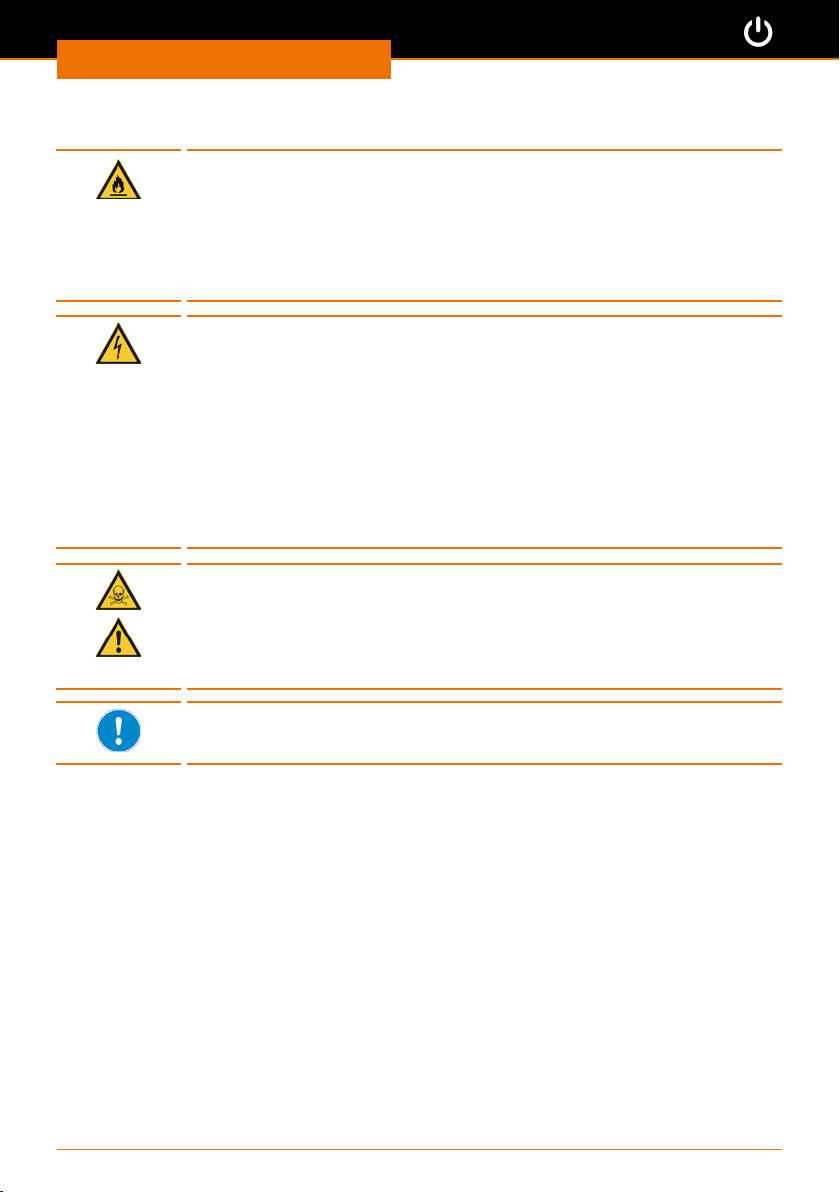
Danger:
Fire hazard
If you ll the device with a thermal uid with too low a ash point, it
may catch re.
Only use thermal uids with a ash point that is at least 20 K above
the temperature range for the application. Do not use ethanol as an
additive due to its highly ammable properties.
Warning:
Risk of electric shock
If the device is overlled, thermal uid may overow into the device
and cause the device to short circuit.
Ensure that the device is not overlled. Carefully monitor the ll level
indicator and the thermal expansion of the thermal uid.
Warning:
Risk of electric shock
If the device is lled carelessly, thermal uid may splash into the device
and cause the device to short circuit.
Use a funnel for lling. Avoid splashing the thermal uid.
Warning:
Risk of poisoning! Risk of injury!
When handling chemically prepared thermal uids, any splashes could
cause injuries to areas of bare skin.
Always wear safety goggles, protective gloves and protective clothing
when lling the chiller.
The thermal uid from Heidolph is suitable for all standard applications.
It covers a temperature range from minus 30 °C to plus 90 °C. (See
chapter “Spare parts and accessories, Accessories”)
14
Page 15
Start-Up
Filling for the rst time
The reservoir for the thermal uid can hold between 20 and 33 litres (see chapter
“Attachments, Technical data”).
Filling of the device is supported by a software program. If the ll level is too low:
▪ the pump and cooling unit will not start
▪ the Fill mode starts automatically.
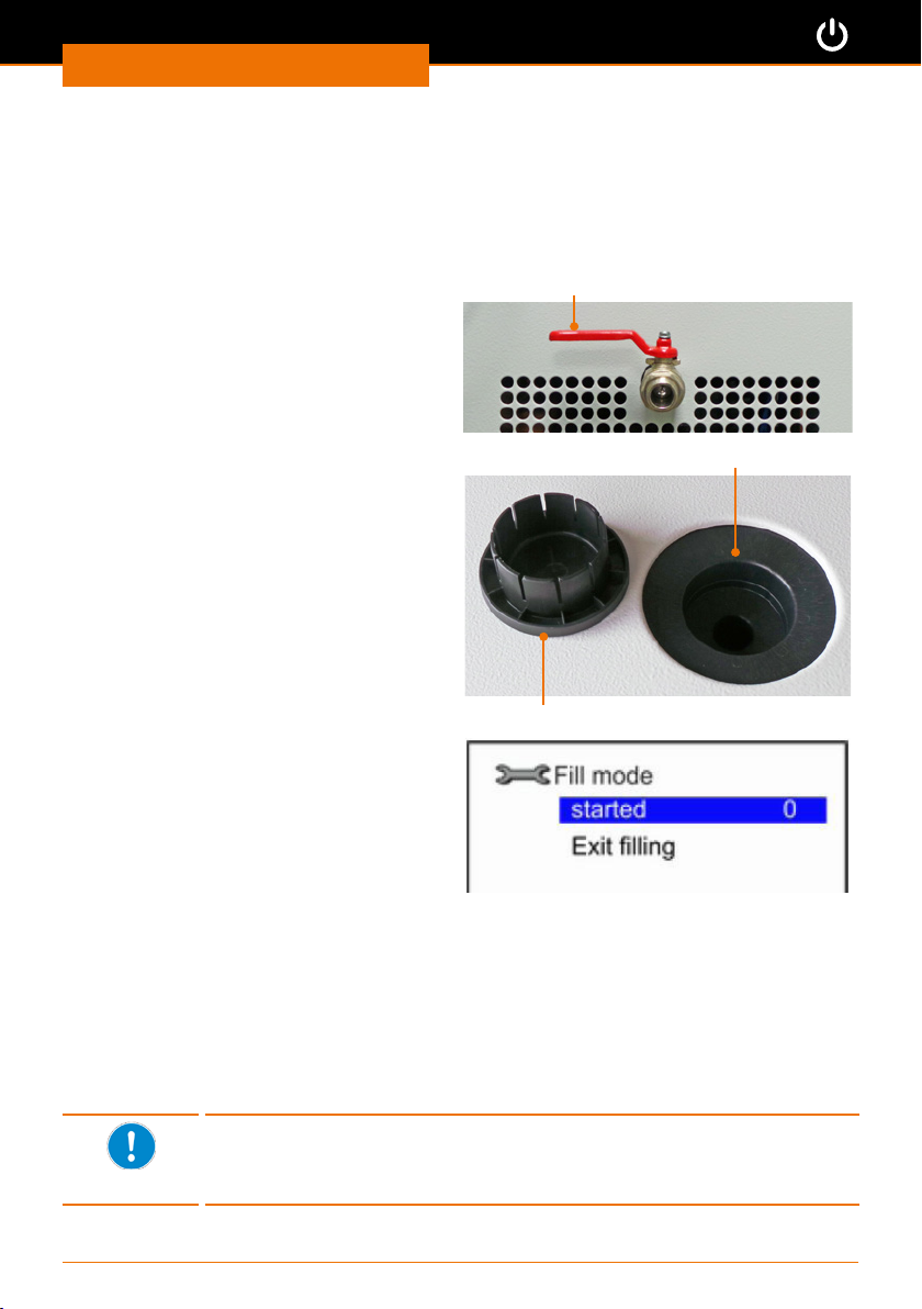
➜ Close the drain valve by turning the valve
fully to the left.
Emptying cock closed
✓ The device is switched on.
✓ The " Fill mode" submenu appears on
the display.
➜ Carefully remove the cover for the
lling pipe by pulling it upwards.
➜ Carefully ll the reservoir with thermal
uid via the lling pipe using a funnel.
Sealing cap for reservoir
✓ The display shows the value "0" as the
ll level to the right of "started".
➜ Observe the ll level indicator.
➜ An acoustic signal sounds at intervals
once the value has risen to 4-5.
✓ The device is lled suciently.
➜ Connect your external consumer (see chapter “Assembly, Peripheral connections”).
➜ Press the "Standby" softkey to ll the external consumer.
➜ Continue to rell thermal uid until the ll level rises to 4-5 again and an acoustic signal
will sound.
➜ End the lling process and close the reservoir with the cover.
➜ Press the down
➜ Press the "ESC" softkey to exit the "Fill mode" menu.
✓ You return to the base menu.
arrow button to select “Exit lling”.
ˇ
The intervals between the signal tones are shortened until a contin-
uous tone is heard if the lling process does not end. A continuous tone
indicates that the device is overlled and cannot be started. Before
starting the pump, some thermal uid must be drained rst
Filling pipe for reservoir
15
Page 16
Start-Up
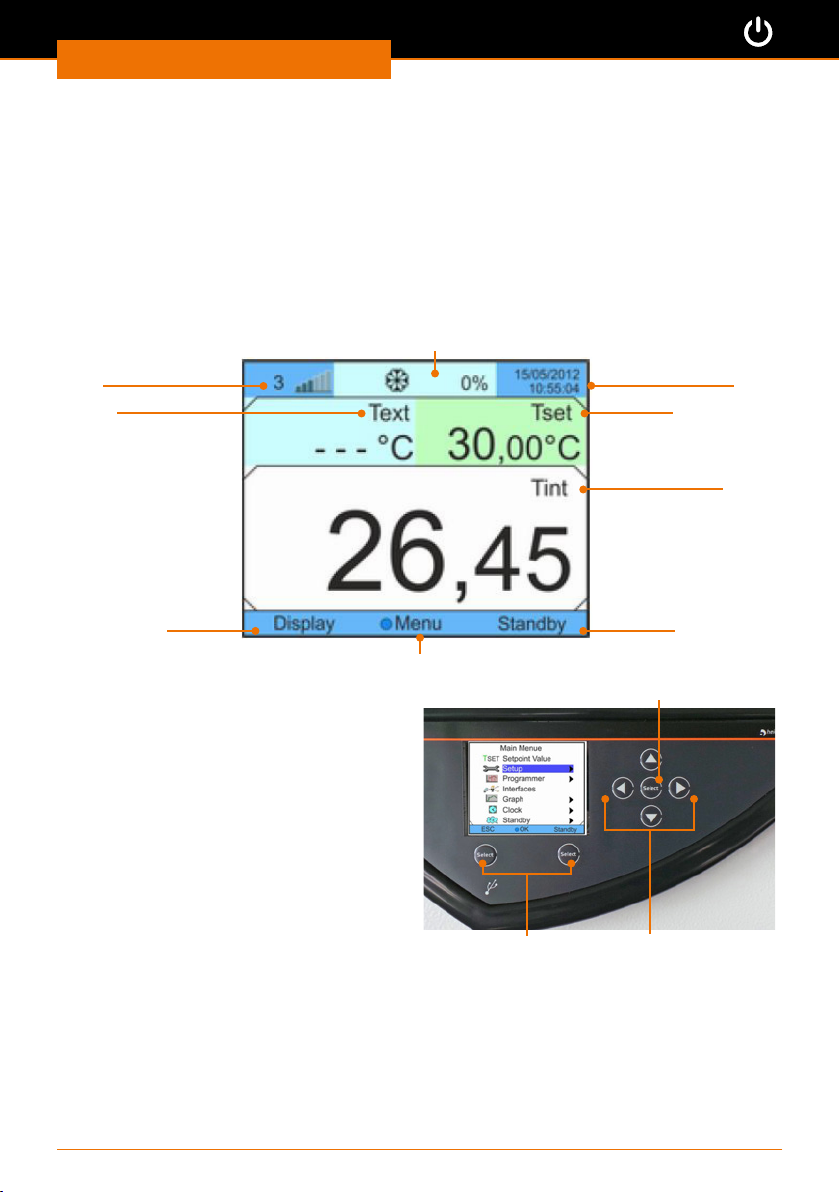
Menu navigation
From the base menu, you reach the main menu, which is divided into 6 submenus. Some
of these submenus have up to 4 further submenus.
(see the following chapter “Operation, Menu structure Overview”)
Base menu
➜ Switch the device ON.
✓ A signal tone sounds.
✓ The base menu will be displayed after the welcome screen.
Current capacity of the total cooling output
Current ll
level
Actual
external temperature
Date and
time
Temperature
setpoint
Current layout
softkey right
Current layout of the button “Select”
➜ Press the button “Select” .
✓ The main menu will appear.
Main menu
➜ Press the up p or down q arrow
button.
✓ The various menu options are selected
and highlighted in colour.
✓ An arrow u after a menu option refers
to a further submenu.
➜ Press the button “Select” to call up a
selected submenu.
✓ Either another submenu or the set
value for the called up parameter will
be displayed.
internal temperature
Actual
Current layout
softkey right
button “Select”
Arrow buttonsSoftkeys
16
Page 17
Start-Up
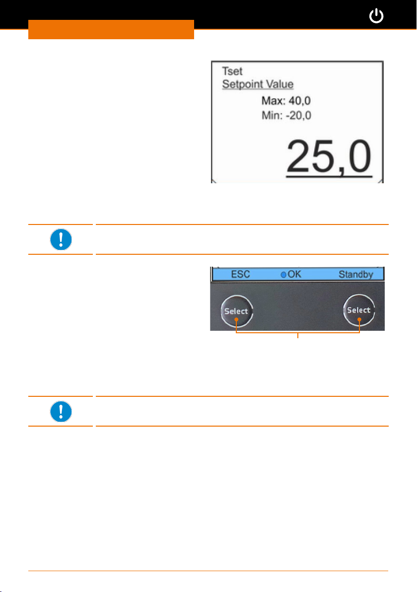
Submenu for setting of values
✓ A cursor ashes under the currently set
value.
➜ Press the right u or left t arrow button
to select a number.
➜ Press the up p or down q arrow button
to change the number.
➜ Press the right u or left t arrow button
to select the next number.
➜ Conrm the entire value using the
button “Select” .
✓ The set value will be stored.
➜ Press the left t arrow button to return to the previous menu.
➜ Press the left softkey under “ESC” to return to the base menu.
If you press the "ESC" softkey without rst conrming the value with
the Enter key, the changes will not be stored.
Softkeys
The softkeys always call up the function
displayed in the footer above.
✓ You are in a submenu.
➜ Press the left “ESC” softkey.
✓ You will be taken directly to the base
menu from any submenu.
➜ Press the right “Standby” softkey.
✓ The device will be switched immedi-
ately to the standby or the temperature
control mode from any menu.
Softkeys
With a few exceptions, the softkeys in each menu and submenu are
assigned the "ESC" and "Standby" functions.
17
Page 18
Start-Up
Presettings
Selecting the language
(See chapter “Startup, Selecting the language”)
Setting the temperature limit
Before placing the chiller into operation, the desired temperature setting needs to be
entered depending on the thermal uid being used.
Warning:
Risk of poisoning! Risk of injury!
Each thermal uid covers a certain temperature range. If the temperature exceeds or drops below this temperature range, it could damage
the device and cause the thermal uid to escape. Escaping thermal
uids can lead to slipping and poisoning.
Check the permissible temperature range for the thermal uid being
used and carefully set the temperature limits on the device.
The desired cooling temperature is maintained by dening the following two variables:
▪ Temperature limit:
denes the upper and lower maximum values that must not be exceeded. As soon as
the temperature exceeds or falls below these values, a warning signal will sound.
▪ Temperature setpoint:
denes the cooling temperature for the thermal uid. Until this setpoint is reached,
the current temperature will uctuate above and below this setpoint and thus also
between the upper and lower temperature limits.
Both values for the temperature limits are dependent on the thermal uid being used
(see also chapter “Spare parts and accessories, Spare parts”).
Setting the upper temperature limit
✓ The device is switched on.
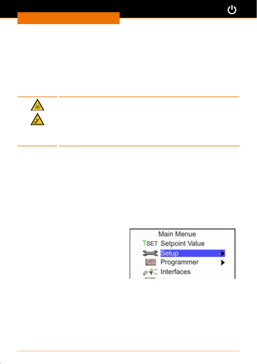
➜ Select the “Setup” menu option from
the main menu.
➜ Press the button “Select” .
➜ Select the menu option “Temp. limits”
from the “Setup” submenu.
18
Page 19
Start-Up
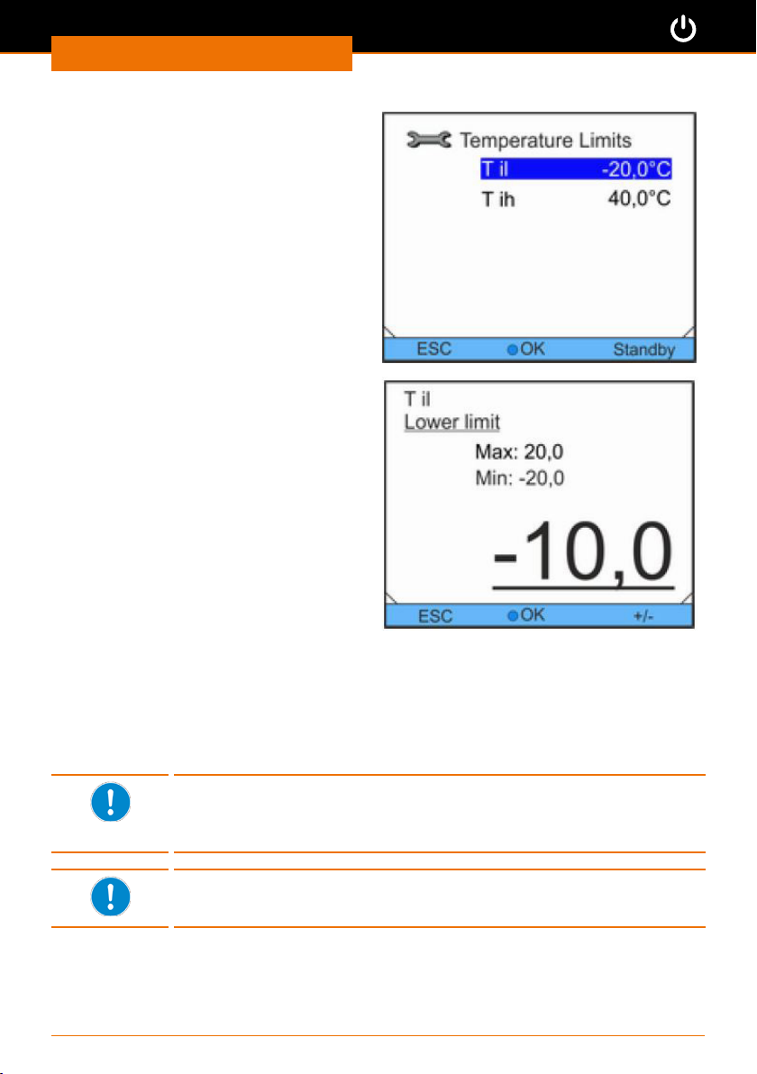
✓ The “Temperature limits” submenu
appears.
➜ Press the up p or down q arrow button
to select the lower limit “Til” or the
upper limit “Tih”.
➜ Conrm “Til” using the button “Select” .
✓ The “Lower limit” submenu appears.
✓ A cursor ashes under the set value.
➜ Correct the currently set value using
the arrow buttons right u or left t and
up p or down q.
➜ Conrm the entire desired value using
the button “Select” .
✓ The set value will be stored.
➜ Return to the “Temperature limits”
submenu using the left arrow
button t.
➜ Press the left softkey under “ESC” to
return to the base menu.
Setting the upper temperature limit
➜ Repeat the procedure for the upper limit value
Setting the temperature setpoint
The adjustable temperature range for the setpoint is automatically
limited by the temperature limits. It can be set to a maximum of 2 °C
below the upper temperature limit and 2 °C above the lower tempera-
ture limit.
At a temperature setpoint or current temperature < 5 °C, the yellow
LED on the device will light up. It warns you about the possible incorrect use of the thermal uid and resulting damage to the device.
19
Page 20
Start-Up
✓ The device is switched on.
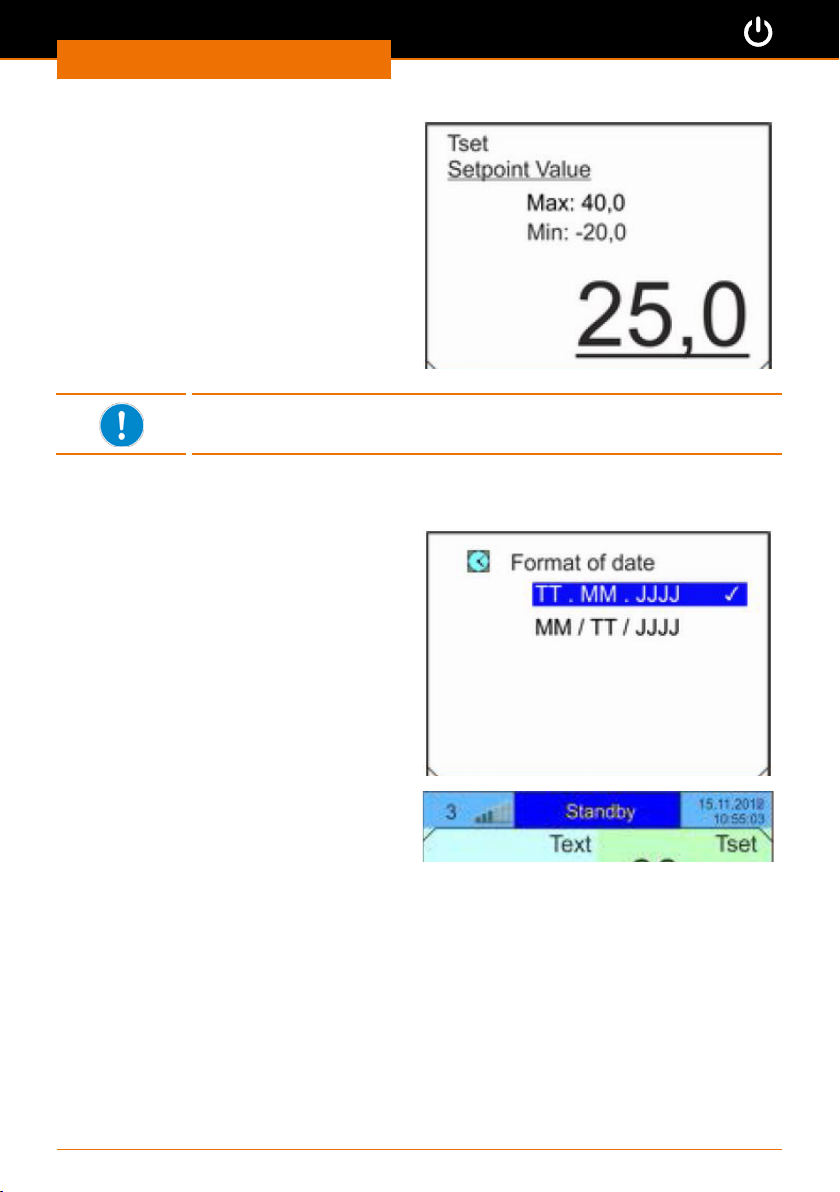
➜ Select the “Setpoint value” menu
option from the main menu.
✓ A cursor ashes under the set value.
➜ Use the arrow buttons to enter the
desired temperature setpoint.
✓ The value must be between the
displayed “Max.” and “Min.” values.
➜ Conrm your selection using the
button “Select” .
If the entered setpoint is outside of a dened temperature limit, a
warning signal will sound. The value will not be saved.
Setting the date and time
✓ The device is switched on.
➜ Select the submenu “Clock” / “Set
Time/Date”.
➜ Use the arrow buttons to enter the
current time and the current date and
conrm the entry using the button
“Select” .
➜ Set the desired display for the date in
the "Format/Date" submenu.
✓ Date and time will be displayed on
the top right of the base menu in the
header according to your setting.
20
Page 21
Operation
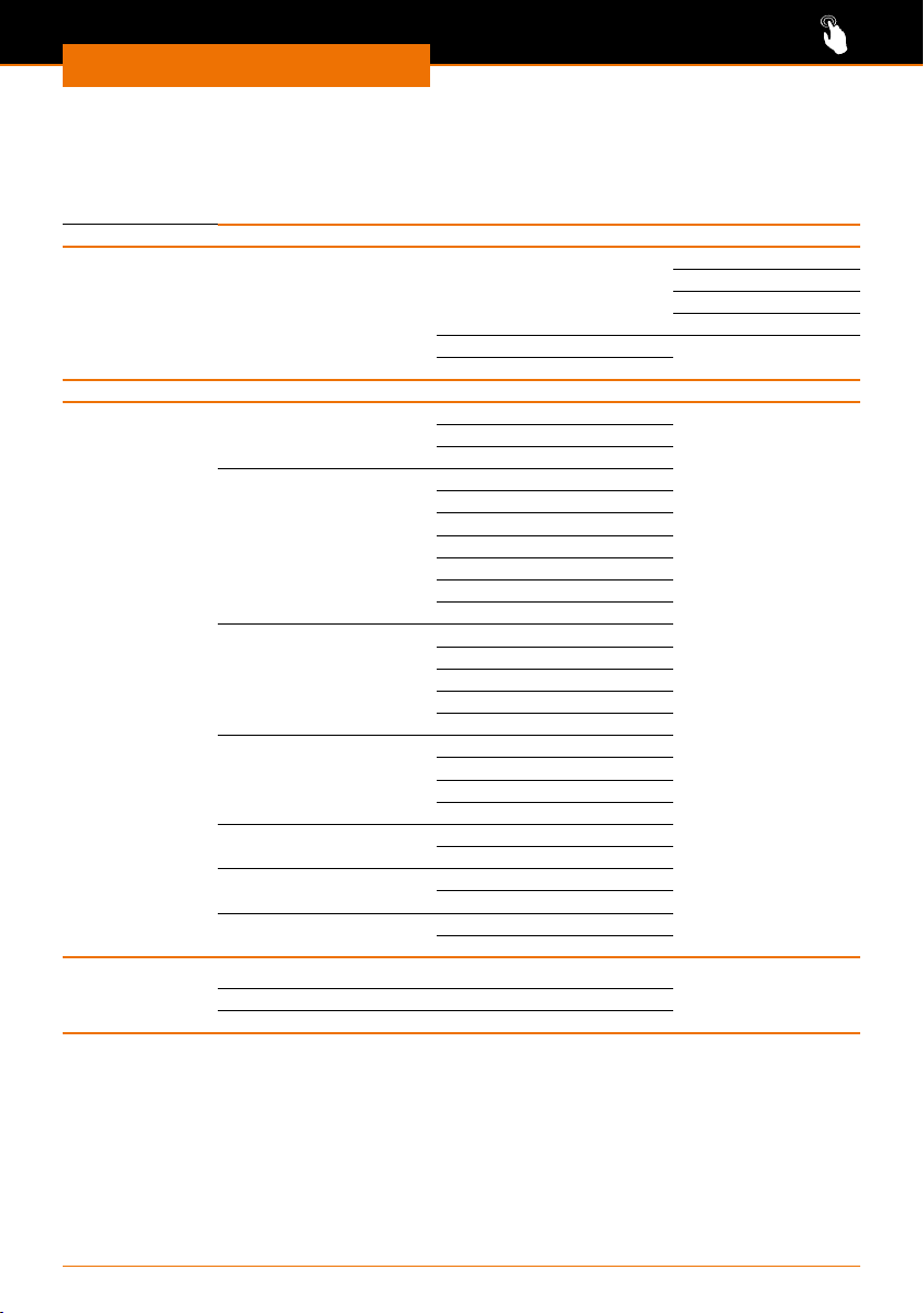
Menu structure Overview
Main menu
Setpoint Value
Setup (see following page)
Programmer Program 1 - 5 Status Start
Interface
Graph Mode Online graph
Displayed Value Tset Tint Text
Sample Time 2 s (max.2h10min)
Time axis Automatic
Time base absolute
Temperature scale automatic
Temperature limits Temp.Scale Min -13 °C
Clock
Standby
Set time and date
Format of date DD.MM.YYYY
Operation
Stop
Hold
Continue
Edit
Loop
Record Start
Freeze graph Start
Tset Tint
Tset Text
Tint Text
Tint
Text
Tset
10 s (max.11h5min)
30 s (max.33h20min)
1 min (max.66h40min)
2 min (max.133h)
9 min
45 min
2 h 15 min
relative
manual
Temp.Scale Max 40 °C
MM.DD.YYYY
21
Page 22
Operation
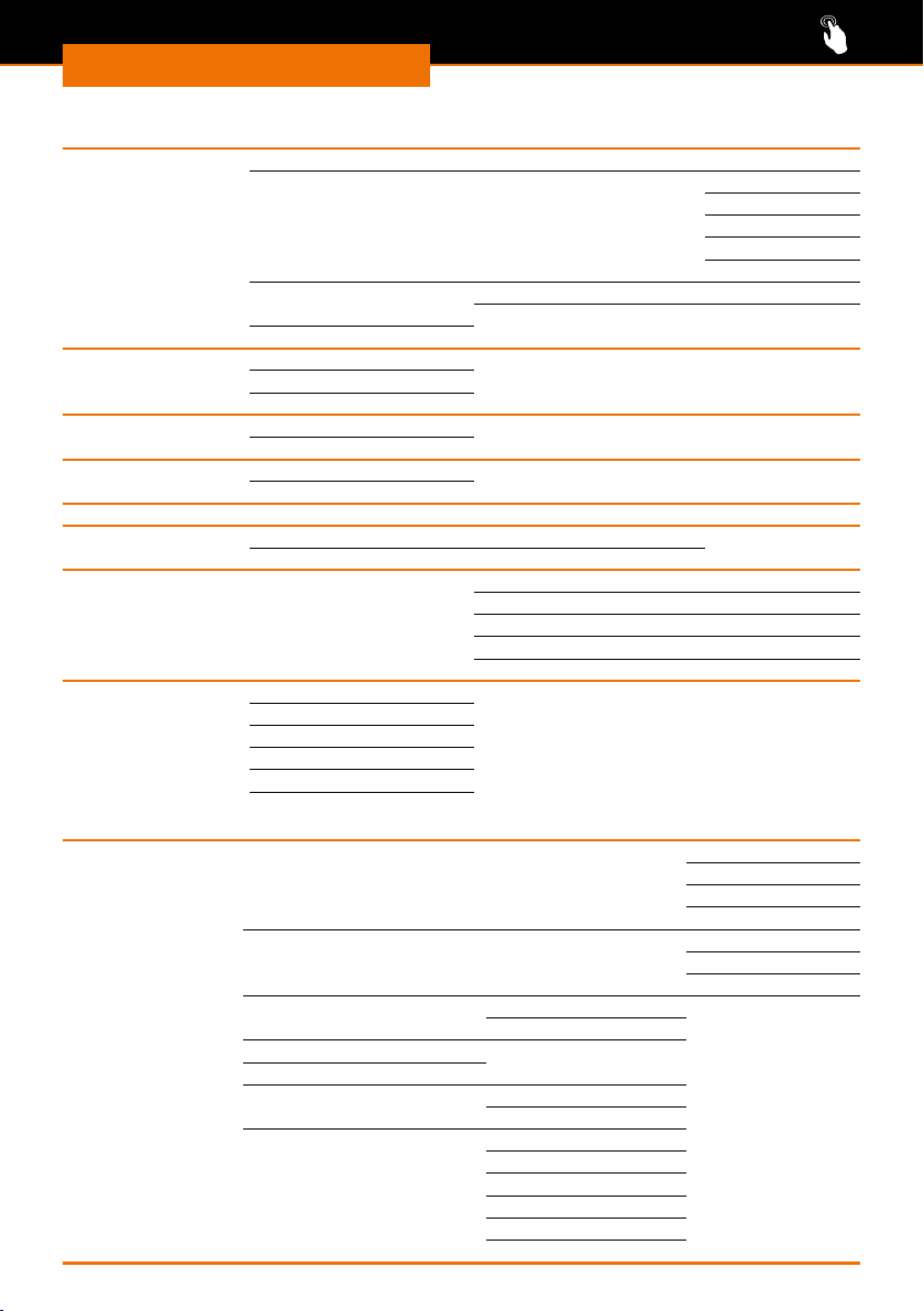
Sub menu setup
Control Control variable intern Pt 1000
Control parameter intern Pt 1000 Xp
Setpoint oset Oset source o
1
Correction limit
50.0
Cooling autom. o
on
automatic
Limits Lo. limit (Til)
Up. limit ((Tih)
Fill mode Started
Stop ll mode
Basic setup (see following page)
Calibration Calibration
Factory Calibration no/yes
Factory setting All default no/yes
Control Reset all no/yes
Device status Fehlerspeicher
Gerätedaten
SW-Version
Typ ......................
Seriennummer
Di.set/actual value
ctrl. parameter intern no/yes
internal Pt1000 no/yes
miscelaneous no/yes
Tn
Tv manual/auto
Tv
Td
2
0.0
Sub menu Basic setup (submenu of setup menu)
Basic setup Sounds Alarm loud
Warn. medium
Error low
o
Display Brightness automatic
Stage 5 ... 1
o
Autostart o o
on
Curr consumption 14.0A
Warn level niveau 1
Alarm output: Standby Only alarm
Alarm and Standby
Language English
Deutsch
Francais
Español
Italiano
русский
22
Page 23
Operation
Temperature control operation
Caution:
Possible damage to the device
If the ventilation openings are not kept free, the motors for the pump
and compressor could overheat.
Never cover the ventilation grille. Ensure that there is always a
distance of 50 cm between the device and wall or other devices.
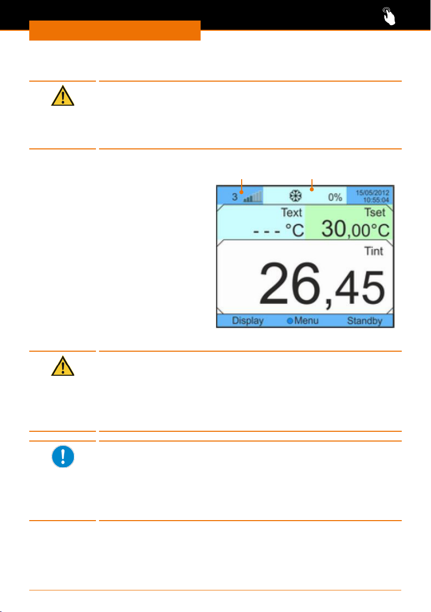
✓ All peripheral devices are securely
connected, and the refrigerant can
circulate freely.
✓ The device is lled with thermal uid
➜ Switch the device ON.
✓ The display shows the base menu with
the current cooling temperature "Tint".
✓ The ll level indicator for the thermal
uid is between 4 and 5.
➜ Press the “Standby” softkey.
✓ The pump for circulating the thermal
uid will start.
✓ In the header “Standby” will be replaced
by the display of the active cooling.
➜ Monitor the ll level indicator and rell the device with thermal uid if necessary.
Caution:
Possible damage to the device
If you set the chiller to cool down to a minus temperature, it is
possible that the thermal uid will freeze.
If you want to cool the device down to minus temperatures, ensure
that you are using an appropriate thermal uid.(See also chapter
“Spare parts and accessories, Spare parts”)
If there is a large dierence in temperature between the chiller and
the external consumer, the temperature drop between the two devices
could be so high that it will not be possible to maintain the cooling
output.
In this case, increase or decrease the setpoint for the cooling tempera-
ture accordingly or ensure that there is a lower volume of items to be
cooled in your external consumer.
Fill level indicator
Base menu
Cooling active
23
Page 24
Operation
Adjusting the pump pressure
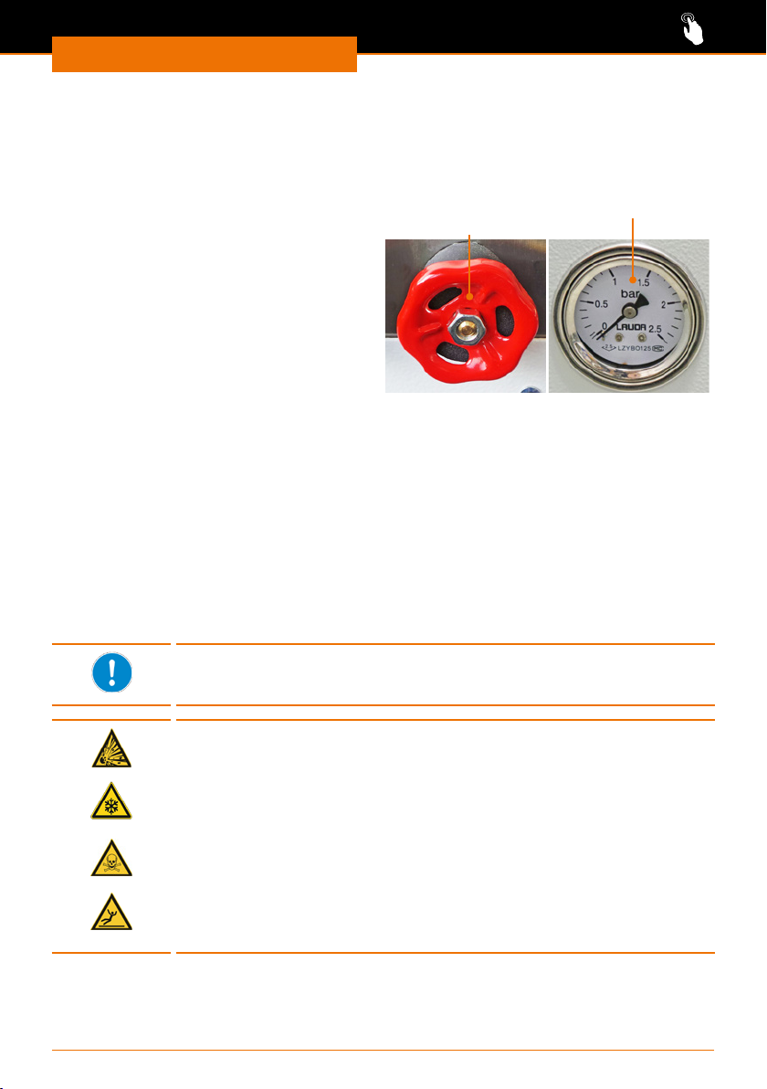
There is an adjusting wheel on the rear of the unit. It allows you to adjust the pressure
for the circulation of the thermal uid according to your application.
The maximally attainable pressure is 2 bar.
You can read the adjusted pressure on the
pressure gauge on the front of the device.
➜ Turn the adjusting wheel clockwise to
adjust the pressure.
✓ The pump pressure will increase.
➜ Turn the adjusting wheel anticlockwise
to adjust the pressure.
✓ The pump pressure will decrease.
✓ The pressure gauge displays the
pressure in bar.
Adjusting wheel
Pressure adjustment
Pressure gauge
Special functions
Standby operation and autostart
In standby mode, the device is in an idle state when it is switched on. All displays can be
called up in standby mode.
If the standby mode is deactivated or autostart is activated and the unit contains sucient temperature control uid, the unit starts to cool immediately when it is switched on
and after a power interruption.
Standby mode is activated when the device is delivered.
Do not change this setting when using the device to cool the Hei-VAP
Industrial rotary evaporator! The chiller is switched on and o via the
rotary evaporator.
Warning:
Risk of explosion!Risk of frostbite! Risk of poisoning! Risk of
injury! Risk of slipping!
If the device automatically resumes full operation after a power
failure, loose screw connections or defective glass containers could
result in the uncontrolled escape of liquids. The liquids that may
escape as a result pose a risk of frostbite, poisoning and slippage.
Burst glassware also poses a signicant risk of injury and can result in
exothermic reactions.
If you have activated the autostart function, do not leave the chiller
and connected peripheral devices unsupervised under any circumstancesCheck that the hose connections are secure at regular intervals.
Only work with awless glass containers.
24
Page 25
Operation
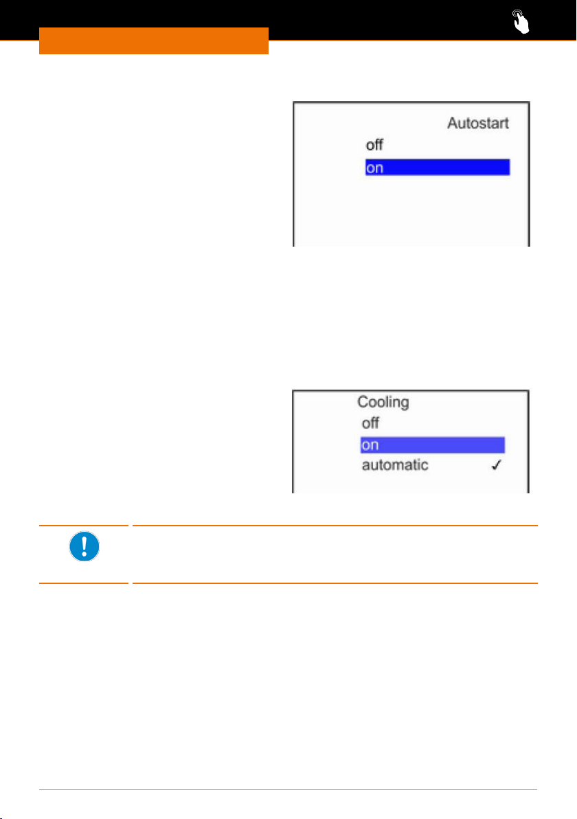
Activating / deactivating the autostart
✓ The device is switched on.
➜ Select the submenu “Setup” / “Basic
settings” / “Autostart”.
➜ Use the arrow buttons to select “on”
and conrm your selection using the
button “Select” .
✓ Autostart is activated.
➜ To switch to standby mode, select the
"o" option from the "Autostart" menu.
Setting the operating mode for the cooling unit
The cooling unit can be controlled both automatically and manually.
The setting is “automatic” when the device is delivered.
▪ “o” deactivates the cooling unit until it is activated again
▪ “on” activates the cooling unit permanently until another option is selected
▪ “automatic” switches the cooling unit automatically on or o when needed.
✓ The device is switched on.
➜ Select the submenu “Setup” /
“Cooling”.
➜ Use the arrow buttons to select one
of the presented options and conrm
your selection using the button
“Select” .
✓ The changed operating mode is
activated.
The ow line temperature for automatic control of the cooling unit is
±2 K from the setpoint. Under certain ambient conditions, this may
lead to longer downtimes of the cooling unit.This does not impair the
cooling output.
25
Page 26
Operation
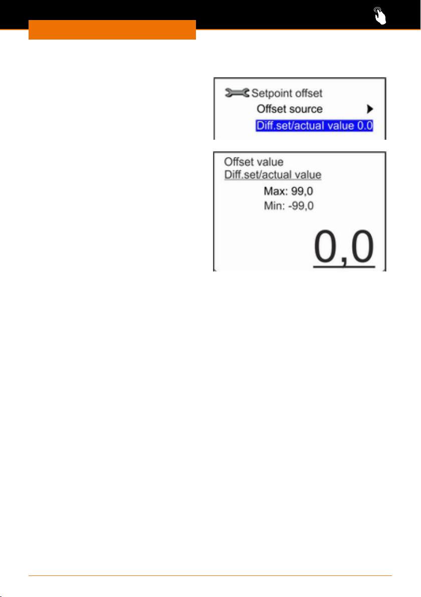
Setting the setpoint oset
✓ The device is switched on.
➜ Select the submenu “Setup” /
“Control” / “Setpoint oset”.
➜ Use the arrow buttons to select one
of the presented options and conrm
your selection using the button
“Select” .
Dierence setpoint / actual value
➜ Select the “Di. set/actual value”
option to determine the upper and
lower limit for the setpoint oset.
➜ Conrm your changes using the button
“Select” .
26
Page 27
Operation
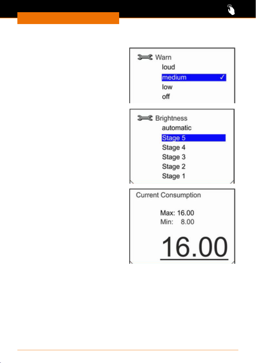
Adjusting the basic settings
Adjusting the volume of the signal
tones
✓ The device is switched on.
➜ Select the submenu “Setup” / “Basic
settings” / “Sounds”.
➜ Use the arrow buttons to select one
of the presented options and conrm
your selection using the button
“Select” .
Adjusting the brightness of the
display
✓ The device is switched on.
➜ Select the submenu “Setup” / “Basic
settings” / “Display” / “Brightness”.
➜ Use the arrow buttons to select one
of the presented options and conrm
your selection using the button
“Select” .
Restricting the power consumption
If your mains fuse is less than 16 A, the
power consumption can be reduced gradually from 16 A to 8 A.
✓ The device is switched on.
➜ Select the submenu “Setup” / “Basic
settings” / “Power consumption”.
➜ Use the arrow buttons to adjust the
power consumption and conrm your
changes using the button “Select” .
27
Page 28
Operation
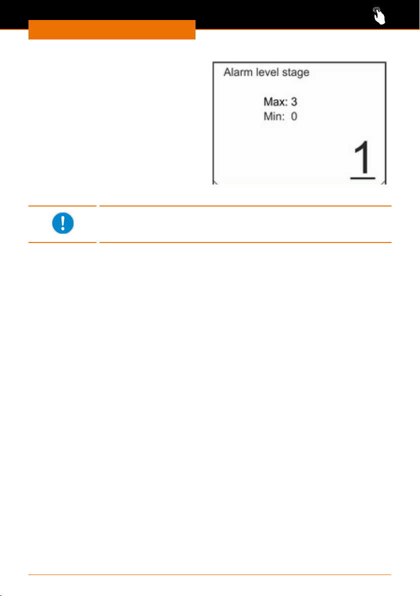
Specifying the minimum ll level
warning stage
On delivery, the device is congured such
that a low level warning is output at a
ll level beginning at level 2. This lower
warning level can be adjusted between 0
and 3.
✓ The device is switched on.
➜ Select the submenu “Setup” / “Basic
settings” / “Warning level niveau”.
➜ Use the arrow buttons to adjust the
warning stage and conrm your
changes using the button “Select” .
No warning will be output if you set the warning stage to "0". Cooling
mode is switched o as soon as the lowest ll level is reached. A
corresponding alarm message will be shown on the display.
28
Page 29

Operation
Control parameters
The control parameters for cooling the device are set to a thermal uid with water when
the device is delivered. Depending on the application and the thermal uid used, it may
become necessary to adjust the control parameters.
The quality of the control system deteriorates at increasingly lower temperatures due to
the change in viscosity of the thermal uid at low temperatures. This means that if you
work with a normal cooling temperature of -20 °C, for example, the control parameters
should be adjusted at an operating temperature of -10 °C.
Please keep this in mind when setting the control parameters.
Internal control parameters
The internal control parameters compare the internal setpoint temperature with the ow
line temperature. This calculation results in the control variable used for cooling.
Parameter Designation Explanation Unit
Xp
Tn
Tv
Proportional range Species the temperature range in which
the proportional component (P component) of the controller is 0 ... 100 % of the
maximum control variable.
For example, if the control deviation is 2 K
with an Xp of 10 K set, the P component
is 20 % of the control value. For a control
deviation of 10 K and more, the P component is 100 % of the control variable.
Reset time Is decisive for the integral component
(I component) of the control variable.
It species the interval during which an
existing control deviation is integrated.
The larger Tn is, the slower the control
deviation is integrated. This makes the
control slower. A smaller Tn makes the
control more dynamic and nally leads to
oscillations.
Rate time This forms the dierential component (D
component) of the control variable. It
inuences the approach speed of the actual
value to the setpoint and counteracts the P
and I components.
The higher the setting for the rate time Tv,
the stronger the output signal is dampened. The rule of thumb is:
Tv = Tn x 0,75.
K
s
s.
29
Page 30
Operation
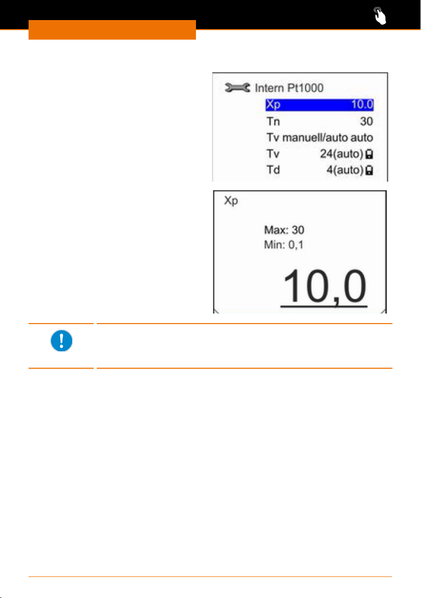
Adjusting the internal control parameters
✓ The device is switched on.
➜ Select the submenu “Setup” /
“Control” / “Control parameters” /
”Internal Pt1000”.
➜ Use the arrow buttons to select one
of the presented options and conrm
your selection using the button
“Select” .
✓ By selecting "Tv manual/auto" you
can specify the option of automatic or
manual control.
✓ When selecting any other option, you
will be able to adjust the highlighted
values.
✓ Conrm the changed value using the
button “Select” .
If the control parameters “Tv manual/auto” is set to automatic control,
the subsequent parameters “Tv” and “Td” are derived using factors
from Tn. They are blocked from changes and indicated by a lock
symbol.
30
Page 31
Operation
Temperature control via programs
In the "Programmer" submenu, you can dene and save the course of a temperature
control over a dened period of time.
They can save up to 5 dierent program sequences. Up to 150 individual steps can be
programmed in each program.
Each of the 5 programs can be repeated between 1 and 250 times or you can loop it in
continuous operation.
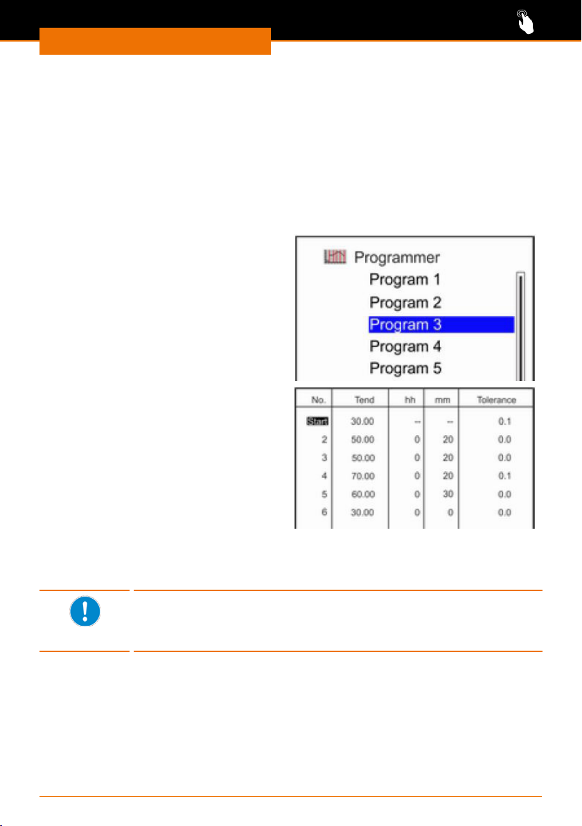
Preparing a program
✓ The device is switched on.
➜ Select the “Programmer” submenu.
➜ Select one of the 5 programs
“Program n”.
➜ Select the “Edit” menu option.
➜ To edit, conrm the rst line with the
button “Select” .
➜ Using the arrow buttons, enter for each
line the following values:
▪ “Tend” the desired end temperature
▪ “hh” the desired number of hours
▪ “mm” the desired number of minutes
▪ “Tolerance” the permissible deviation
from “Tend”.
➜ To be able to edit it, conrm each new
line using the button “Select” .
➜ Conrm your changes using the button
“Select” .
No time “hh” and “mm” can be entered in the rst program line. The
temperature entered here will be approached as fast as possible.
As soon as the specied temperature is reached, the next program line
will be processed.
Changing program parameters
➜ Call up the desired program.
➜ Use the arrow buttons to select a program parameters to be changed.
➜ Conrm the parameter using the button “Select” and change the value.
➜ If necessary, change further parameters and conrm all changes using the button
“Select” .
➜ Use the left arrow button to exit the program.
31
Page 32
Operation
Inserting a program line
➜ Call up the desired program.
➜ Use the arrow buttons to select a program line to be changed.
➜ Conrm the line number using the button “Select” .
✓ A blank program line is inserted below the line.
Deleting a program line
➜ Call up the desired program.
➜ Use the arrow buttons to select a program line to be deleted.
➜ Conrm the line number with the “delete” softkey.
✓ The line is removed from the program.
Change current program
✓ You are in the base menu.
✓ Press the “Prog.x/y” softkey.
➜ Use the arrow buttons to select a program parameters to be changed.
✓ Entire program lines cannot be inserted or deleted during operation.
➜ Conrm the desired parameter using the button “Select” and change the value.
➜ If necessary, change further parameters and conrm all changes using the button
“Select” .
➜ Exit the program using the “ESC” softkey.
The smaller the permissible tolerance is programmed, the more
precisely the desired temperature is maintained. However, as a certain
amount of time is required before a temperature is reached, unwanted
delays may occur if the time specication is tight, since the next
program step will only be processed after the desired temperature has
been reached.
A greater tolerance should therefore be allowed for large temperature
jumps and short time specications.
The duration of a single program step can be a maximum of 999 hours
and 59 minutes. Longer times would have to be distributed to several
program steps.
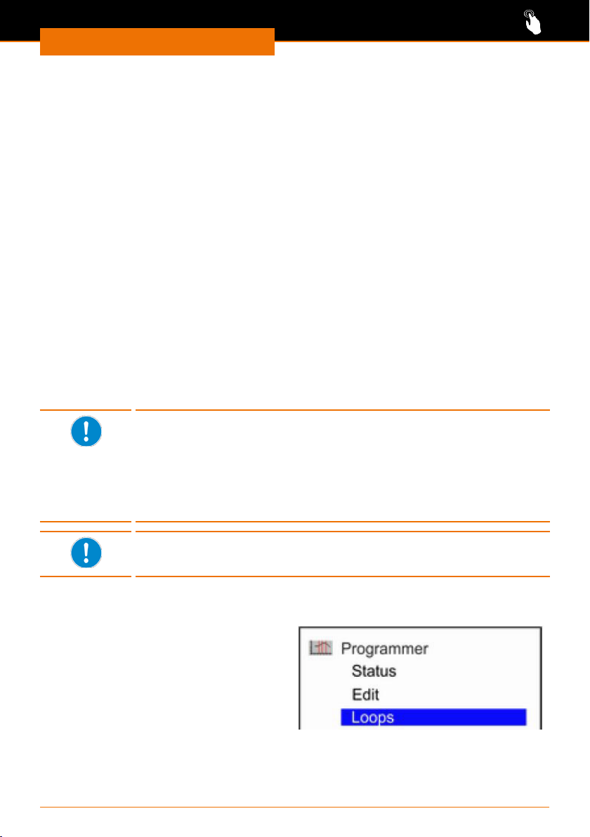
Specifying program runs
✓ The device is switched on.
➜ Select the “Programmer” submenu.
➜ Select one of the 5 programs
“Program n”.
➜ Select the menu option “Loops”.
32
Page 33
Operation
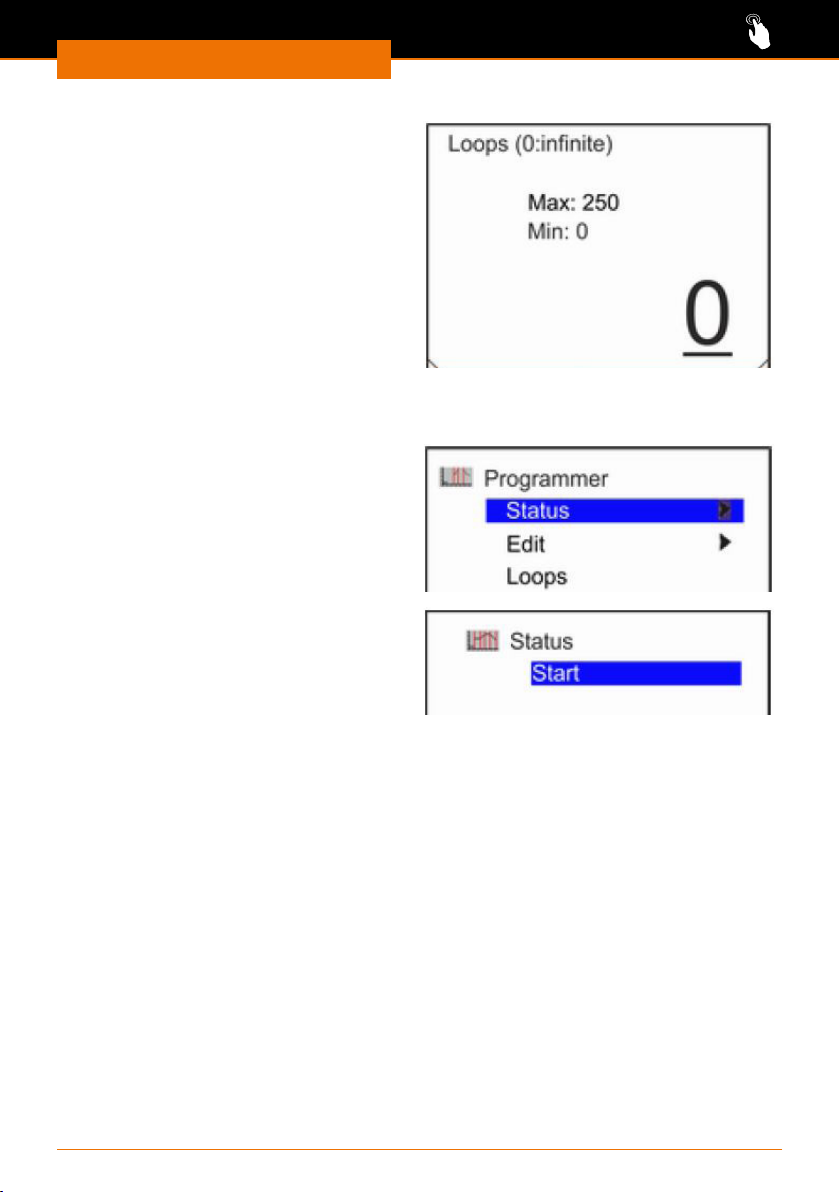
✓ Using the value "0" repeats the
program indenitely.
➜ Press the left arrow button to enter a 2
or 3 digit number.
➜ Use the arrow buttons up/down to
enter the desired number of cycles and
conrm your change using the button
“Select” .
Starting and ending a program
✓ The device is switched on.
➜ Select the “Programmer” / “Status”
submenu.
✓ Only the "Start" option will be
displayed if no program is active.
✓ If a program is activated, the "Pause"
and “Stop” options will be displayed.
✓ If a program has been interrupted
using "Pause," the "Next" and "Stop"
options will be displayed.
➜ Press the button “Select” to conrm
the respective desired option.
33
Page 34

Operation
Device status
You can call up various data stored in the device from the "Device status" menu. Your
device version will be displayed directly under the “Type ...”menu option.
✓ The device is switched on.
➜ Select the submenu “Setup” /
“Device Status”.
➜ Use the arrow buttons to select one
of the presented options and conrm
your selection using the button
“Select” .
➜ Use the left arrow button to return to
the “Device status” menu.
Error memory
(For an interpretation of the error
memory, see chapter: “Troubleshooting,
Malfunctions and troubleshooting”.)
Device data
Here, the actual and setpoint
temperatures are displayed at the various
temperature sensors.
SW Version
Following “Control” the software version
will be displayed.
Serial number
Following “Control” the serial number for
the device will be displayed.
34
Page 35
Operation
Interfaces
Warning:
Risk of electric shock
If the interface inputs and outputs are energised too high and are not
suciently insulated, metallic parts, e.g., the housing, may be energised
in the event of a fault.
Isolate low voltage inputs and outputs over 25 V AC or 60 V DC reli-
ably according to DIN EN 61140, or by double or enhanced insulation
according to DIN EN 60730-1 or DIN 60950-1.
Use only shielded connection cables. Connect the shielding to the
connector.
Caution:
Possible damage to the cooling system
If the connections on the device are not covered, liquids could reach
the live components. Ingress of liquids can lead to malfunctions of the
interfaces and can lead to a short circuit.
The interface connections on the rear of the device must always remain
covered.
In which fault situations a signal is output via the interface can be set
via the display.
35
Page 36
Operation
Connecting the alarm output
The alarm output can be used to output faults to an external device via a potential-free
contact.
Warning:
Risk of electric shock
If the voltages received by the interface inputs and outputs are too
high and not suciently insulated, metal components such as e.g., the
housing could become live in the event of a fault.
Isolate low voltage inputs and outputs over 25 V AC or 60 V DC reli-
ably according to DIN EN 61140, or by double or enhanced insulation
according to DIN EN 60730-1 or DIN 60950-1.
Use only shielded connection cables. Connect the shielding to the
connector. Cover unused connectors with protective caps.
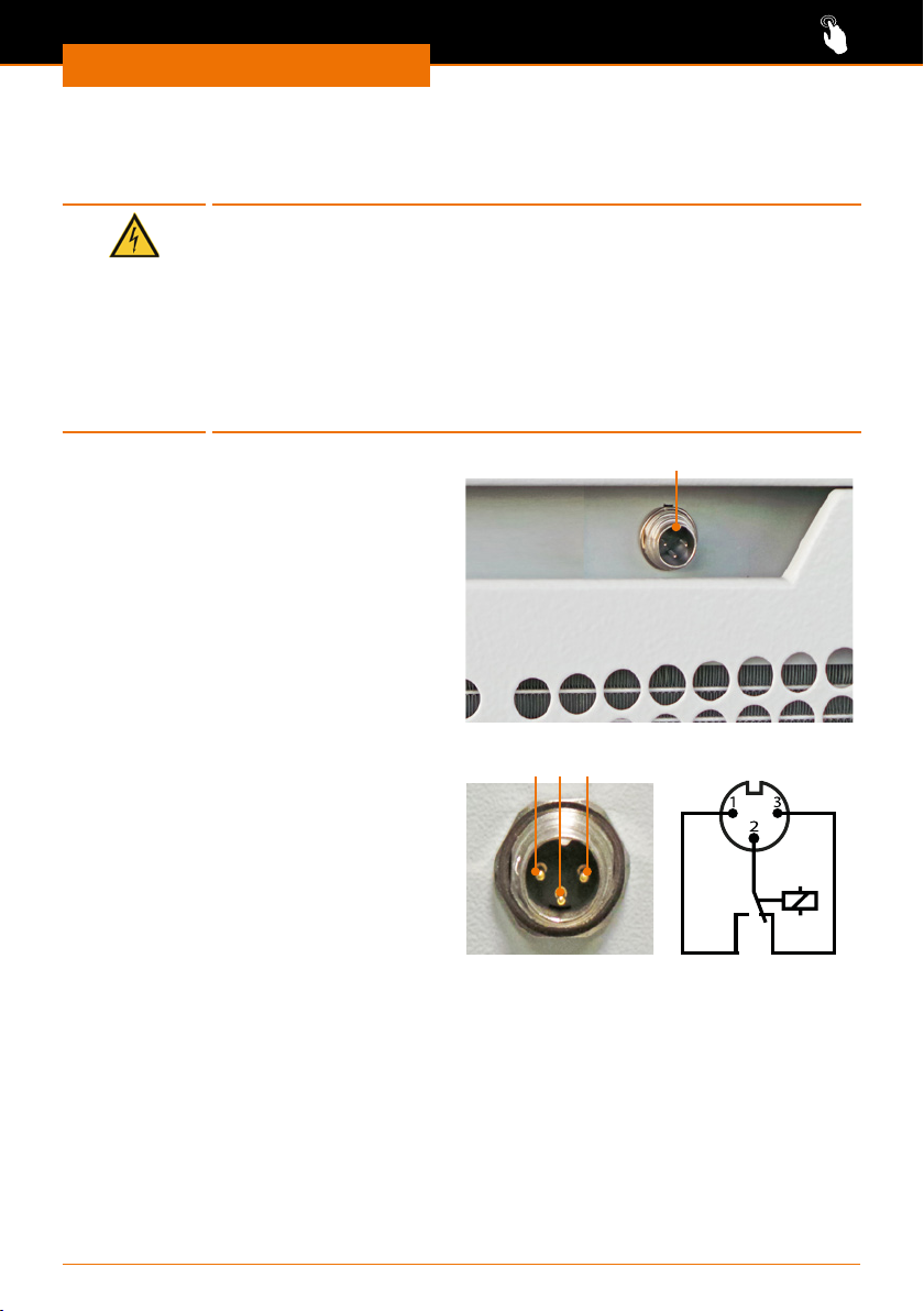
Alarm output
The alarm output is located on the front of
the unit in the handle recess of the ventilation grille.
Conguring the alarm output
The device is congured in the factory to
always output safety-relevant faults to
the alarm output. In addition, you can
congure the alarm output so that an
alarm is also output in standby mode.
A maximum 30 V DC at 0.2A may be
connected to the alarm output.
Idle state
If the device is switched o or there is
a fault after switching it on, the alarm
output is in an idle state:
▪ Pin 1 and 2 are open.
▪ Pin 3 and 2 are closed.
Good state
If the device is switched on and operating without any faults, the alarm output is in a
good state:
▪ Pin 1 and 2 are closed.
▪ Pin 3 and 2 are open.
Alarm output
1
Alarm output
2 3
Alarm output in idle
state
36
Page 37
Operation
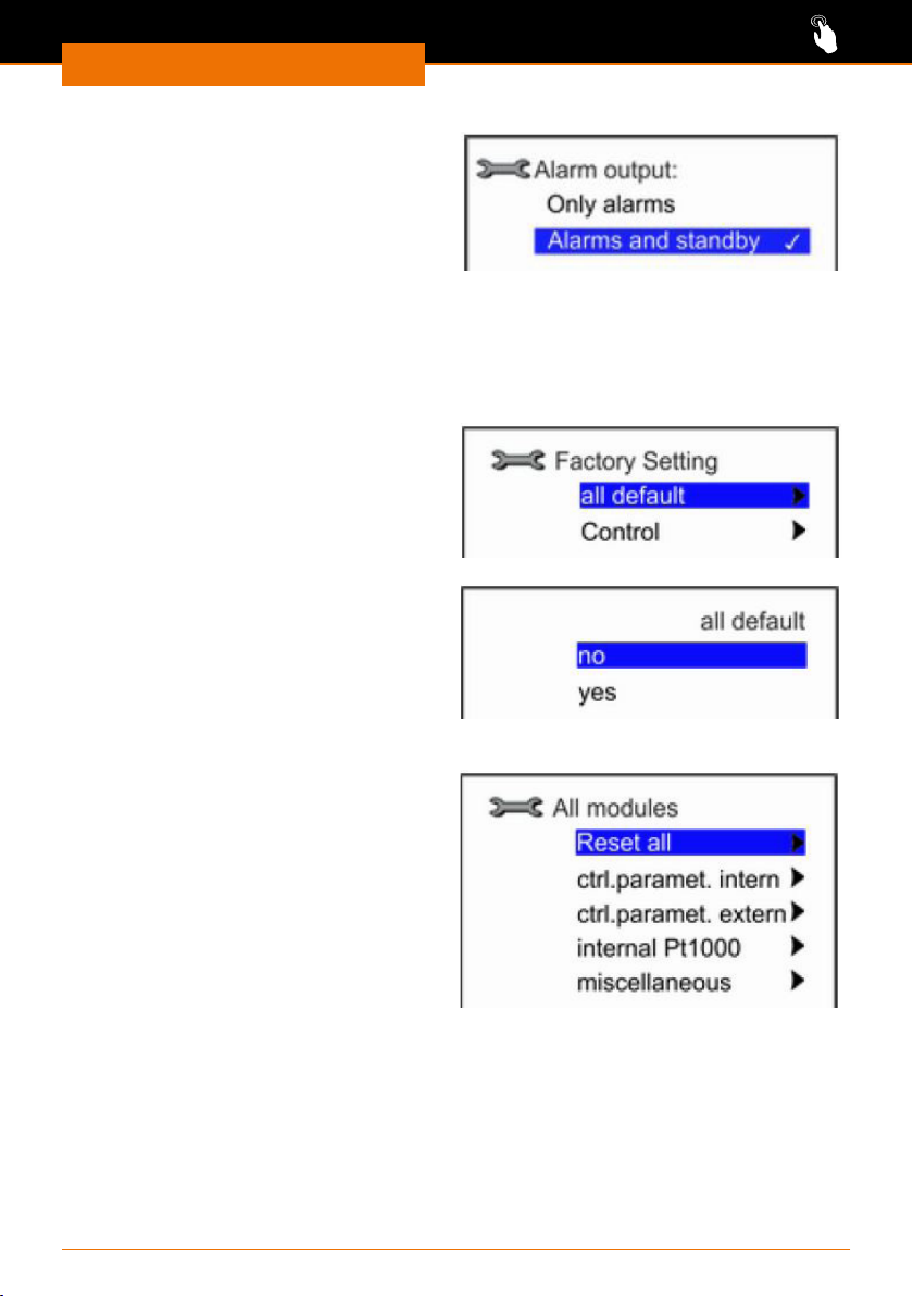
✓ The device is switched on.
➜ Select the submenu “Setup” / “Basic
settings” / “Alarm output”.
➜ Use the arrow buttons to select one
of the presented options and conrm
your selection using the button
“Select” .
Restoring the factory settings
All settings that you have changed in one of the submenus can be restored to the original
factory settings under the “Factory settings” menu option.
✓ The device is switched on.
➜ Select the submenu “Setup” / “Factory
setting”.
➜ Use the arrow buttons to select one
of the presented options and conrm
your selection using the button
“Select” .
Resetting all settings
✓ The device is switched on.
➜ Select the submenu “Setup” / “Factory
setting” / “all default”.
➜ Use the arrow buttons to select one
of the presented options and conrm
your selection using the button
“Select” .
Resetting settings individually
✓ The device is switched on.
➜ Select the submenu “Setup” / “Factory
setting” / “Control”.
➜ Use the arrow buttons to select one
of the presented options and conrm
your selection using the button
“Select” .
✓ For each setting you will be given the
opportunity to conrm with "yes" or
"no".
✓ You can reset the setpoint and the current consumption under "miscellaneous".
37
Page 38
Cleaning and Maintenance
Cleaning
Cleaning and Maintenance
Cleaning the device
The housing and surfaces of the device can be cleaned using a damp cloth and, if
required, a mild soap solution.
Warning:
Risk of electric shock
Liquids penetrating into the device could cause the device to become live
if it is still connected to the power supply.
Before cleaning the device:
▪ Switch the device o.
▪ Disconnect the power cord plug.
Caution:
Device damage
Liquids penetrating into the device could damage the electronics.
Only wipe the surfaces with a damp cloth and not a wet cloth.
Caution:
Damage to surfaces
The surfaces could be damaged by improper cleaning.
Do not use the following under any circumstances:
▪ Chlorine bleach or cleaning agents containing chlorine
▪ Substances containing solvents (e.g., acetone)
▪ Ammonia
▪ Abrasive cleaning agents such as cleaning wool, scouring agents or
cleaning agents with metallic particles
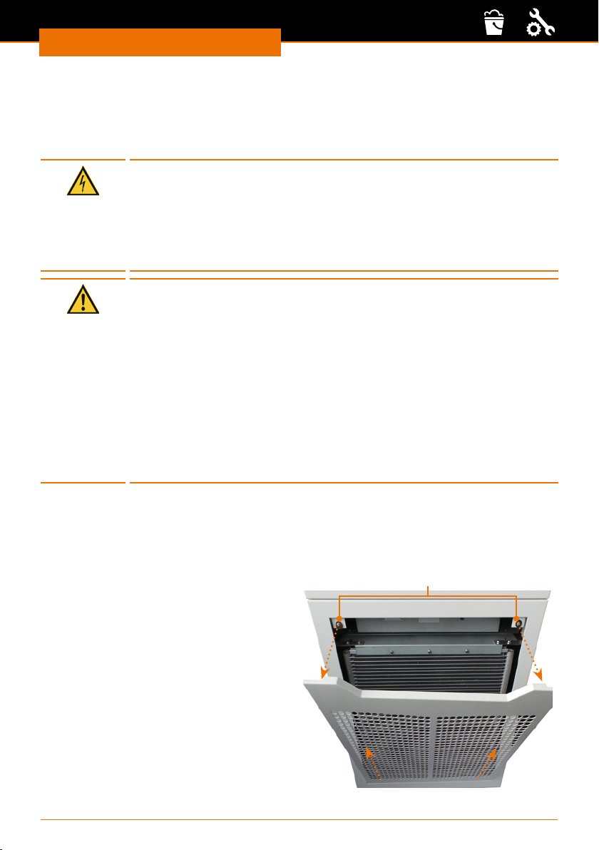
Cleaning the air lter
The ventilation grille in front of the air lter is held by two magnets in addition to the
mechanical bracket.
✓ The device is switched o and disconnected from the power grid.
➜ Use both hands to grab the top grip recess of the ventilation grille.
➜ Pull the ventilation grille o the upper
magnets.
➜ Pull the ventilation grille slightly upwards
and pull it o the retaining lugs at the
bottom of the device.
➜ Brush or vacuum the air lter and, if
necessary, the ventilation grille.
➜ Slide the ventilation grille at the bottom
with the slots over the two retaining
lugs.
➜ Grab the grip recess and carefully push
the ventilation grille back onto the device
at the top.
38
Magnets
Page 39
Cleaning and Maintenance
Maintenance
Maintenance
Danger!
Risk of poisoning! Risk for the environment!
Improper repairs to the internal cooling circuit may result in leaks and
the refrigerant could escape in an uncontrolled manner. This could
result in employees being poisoned and also in serious environmental
damage.
Repair and maintenance work on the internal cooling circuit may only
be carried out by specialist personnel authorised by Heidolph Instru-
ments.
Warning:
Risk of electric shock Risk of injury!
You could come into contact with live or moving parts when carrying
out repairs. This could result in electric shocks, collisions, cutting or
crushing
The device must be disconnected from the power grid before all maintenance work.
Repairs may only be performed by specialist personnel authorised by
Heidolph Instruments.
Warning!
Risk of burns! Risk of frostbite
Touching hot or cold device components, accessories and thermal uid
could result in burns and frostbite.
Always wear protective gloves and protective clothing when carrying
out maintenance work.
Allow the device components, accessories and thermal uid to reach
room temperature before touching them.
If the device has come into contact with hazardous materials, the
device needs to be decontaminated before completing any maintenance work.
39
Page 40
Cleaning and Maintenance
Maintenance intervals
The maintenance intervals stated in the following table must be observed. The following
maintenance tasks are obligatory before all prolonged unsupervised operation.
Interval Maintenance work
▪ Check the drain screw by inspecting it from the outside
monthly
Six monthly Check the thermal uid
Any repairs that may be required may only be performed by a specialist authorized by
Heidolph Instruments.
In this case, contact your Heidolph Instruments dealer or a representative of Heidolph
Instruments.
Checking the thermal uid
Contaminated or degenerated thermal uid must be replaced. Continuing to use the
thermal uid in this case is only permitted after obtaining corresponding test results. The
thermal uid must be checked in accordance with DIN 51529.
▪ Check the external hoses for material fatigue
▪ Clean the air lter
40
Page 41
Troubleshooting
Malfunctions and troubleshooting
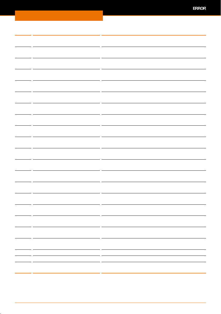
Alarms are relevant to safety. The device will be switched to standby operation.
✓ An acoustic signal will sound rhythmically.
➜ After correcting the cause, press the button “Select” to reset the alarms.
✓ The alarm has been resolved.
Alarms
Code Error Troubleshooting
02 Low level ▪ Check if all connections are securely
Warnings are not relevant to safety. The device continues to operate.
✓ A prolonged acoustic signal will sound that is then repeated periodically.
➜ After correcting the cause, press the button “Select” to reset the warnings.
✓ The warning has been resolved.
1. Warnings control system
Code Error Troubleshooting
001 CAN-receive overow Please contact your local Heidolph Instruments
002 Watchdog-Reset Please contact your local Heidolph Instruments
003 Til limit active Please contact your local Heidolph Instruments
004 Tih limit active Please contact your local Heidolph Instruments
005 Corrupt parameter Please contact your local Heidolph Instruments
006 Corrupt program Check the parameters of your running program
007 Invalid parameter Please contact your local Heidolph Instruments
008 CAN system Please contact your local Heidolph Instruments
009 Unknown module Please contact your local Heidolph Instruments
010 SW Control too old Please contact your local Heidolph Instruments
011 SW Safety too old Please contact your local Heidolph Instruments
012 SW Command too old Please contact your local Heidolph Instruments
Troubleshooting
tightened.
▪ Rell thermal uid
▪ Press button “Select”
distributor
distributor
distributor
distributor
distributor
and change the settings
distributor
distributor
distributor
distributor
distributor
distributor
41
Page 42
Troubleshooting
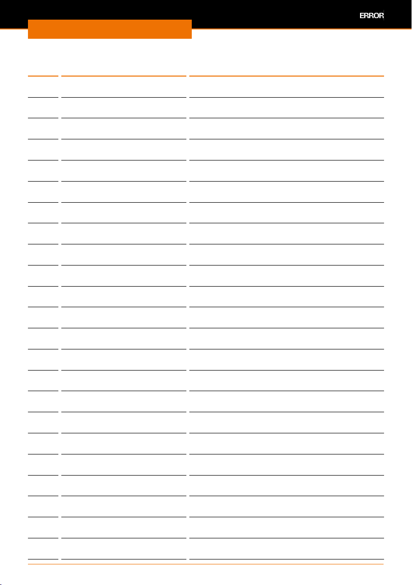
Code Error Troubleshooting
013 SW Command too old Please contact your local Heidolph Instruments
014 SW Analog too old Please contact your local Heidolph Instruments
017 SW Valve 0 too old Please contact your local Heidolph Instruments
018 SW Valve 1 too old Please contact your local Heidolph Instruments
019 SW Valve 2 too old Please contact your local Heidolph Instruments
020 SW Valve 3 too old Please contact your local Heidolph Instruments
021 SW Valve 4 too old Please contact your local Heidolph Instruments
022 SW Pump 0 too old Please contact your local Heidolph Instruments
023 SW Pump 1 too old Please contact your local Heidolph Instruments
024 SW Pump 2 too old Please contact your local Heidolph Instruments
025 SW Pump 3 too old Please contact your local Heidolph Instruments
026 SW HTC too old Please contact your local Heidolph Instruments
028 SW Ethernet too old Please contact your local Heidolph Instruments
029 SW EtherCAT too old Please contact your local Heidolph Instruments
033 Clock wrong time Please contact your local Heidolph Instruments
034 Tset: Prog. is running Please contact your local Heidolph Instruments
041 Wrong mains voltage Please contact your local Heidolph Instruments
042 No VC type Please contact your local Heidolph Instruments
043 No VC voltage Please contact your local Heidolph Instruments
050 Level very low Rell thermal uid
051 Level high Drain thermal uid
055 CAN bu. overow Please contact your local Heidolph Instruments
distributor
distributor
distributor
distributor
distributor
distributor
distributor
distributor
distributor
distributor
distributor
distributor
distributor
distributor
distributor
distributor
distributor
distributor
distributor
distributor
42
Page 43
Troubleshooting
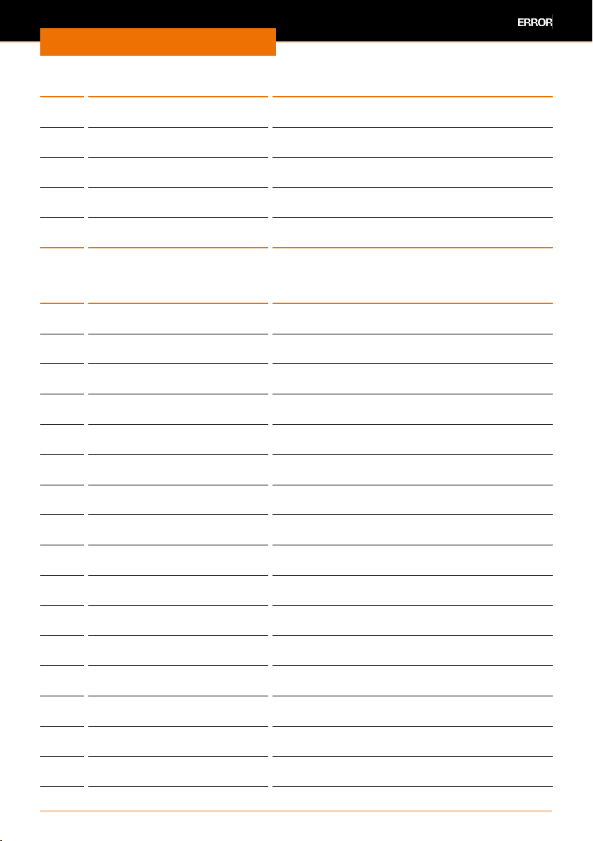
2. Warnings safety system
Code Error Troubleshooting
101 CAN receive overow Please contact your local Heidolph Instruments
102 Watchdog-Reset Please contact your local Heidolph Instruments
103 Heating not correct Please contact your local Heidolph Instruments
104 Heat 1 failed Please contact your local Heidolph Instruments
105 Heat 2 failed Please contact your local Heidolph Instruments
106 Heat 3 failed Please contact your local Heidolph Instruments
107 Invalid parameter Please contact your local Heidolph Instruments
108 CAN system Please contact your local Heidolph Instruments
109 Unknown module Please contact your local Heidolph Instruments
110 SW Control too old Please contact your local Heidolph Instruments
111 SW Safety too old Please contact your local Heidolph Instruments
112 SW Command too old Please contact your local Heidolph Instruments
113 SW Cool too old Please contact your local Heidolph Instruments
114 SW Analog too old Please contact your local Heidolph Instruments
116 SW Contact too old Please contact your local Heidolph Instruments
117 SW Valve 0 too old Please contact your local Heidolph Instruments
118 SW Valve 1 too old Please contact your local Heidolph Instruments
119 SW Valve 2 too old Please contact your local Heidolph Instruments
120 SW Valve 3 too old Please contact your local Heidolph Instruments
121 SW Valve 4 too old Please contact your local Heidolph Instruments
122 SW Pump 0 too old Please contact your local Heidolph Instruments
123 SW Pump 1 too old Please contact your local Heidolph Instruments
124 SW Pump 2 too old Please contact your local Heidolph Instruments
distributor
distributor
distributor
distributor
distributor
distributor
distributor
distributor
distributor
distributor
distributor
distributor
distributor
distributor
distributor
distributor
distributor
distributor
distributor
distributor
distributor
distributor
distributor
43
Page 44
Troubleshooting
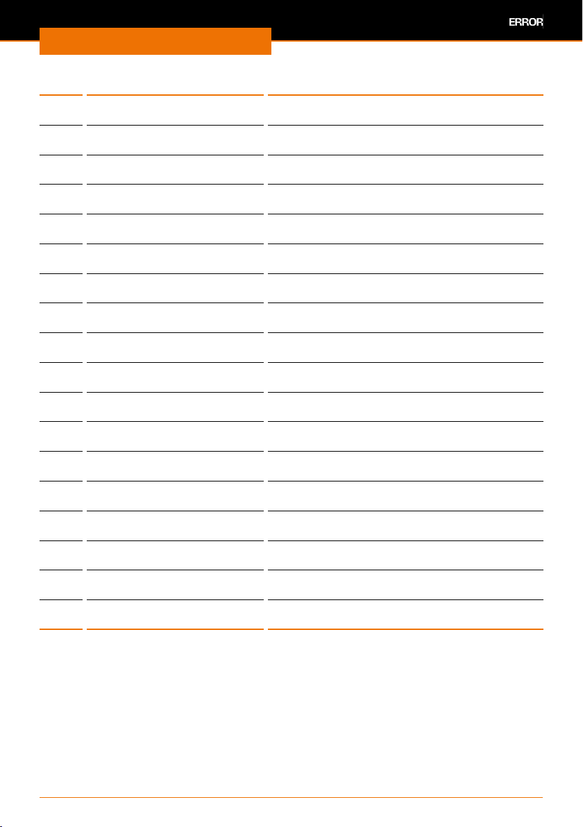
Code Error Troubleshooting
125 SW Pump 3 too old Please contact your local Heidolph Instruments
126 SW HTC old Please contact your local Heidolph Instruments
128 SW Ethernet old Please contact your local Heidolph Instruments
129 SW EtherCAT old Please contact your local Heidolph Instruments
155 CAN bu. overow Please contact your local Heidolph Instruments
3. Warnings refrigeration unit (when set on “automatic”)
Code Error Troubleshooting
301 CAN receive overow Please contact your local Heidolph Instruments
302 Watchdog-Reset Please contact your local Heidolph Instruments
303 Missing SM adaptation Please contact your local Heidolph Instruments
304 Pressure switch activated Please contact your local Heidolph Instruments
305 Clean condenser Clean air lter (see chapter “Cleaning &
306 TO1 out of range (Klixon) Please contact your local Heidolph Instruments
307 Invalid parameter Please contact your local Heidolph Instruments
308 CAN system Please contact your local Heidolph Instruments
309 Unknown module Please contact your local Heidolph Instruments
310 SW Control too old Please contact your local Heidolph Instruments
311 SW Safety too old Please contact your local Heidolph Instruments
312 SW Command too old Please contact your local Heidolph Instruments
313 SW Cool too old Please contact your local Heidolph Instruments
314 SW Analogue too old Please contact your local Heidolph Instruments
316 SW Contact too old Please contact your local Heidolph Instruments
317 SW Valve 0 too old Please contact your local Heidolph Instruments
distributor
distributor
distributor
distributor
distributor
distributor
distributor
distributor
distributor
Maintenance”, section “Cleaning the air lter”.)
distributor
distributor
distributor
distributor
distributor
distributor
distributor
distributor
distributor
distributor
distributor
44
Page 45
Troubleshooting
Code Error Troubleshooting
318 SW Valve 1 too old Please contact your local Heidolph Instruments
319 SW Valve 2 too old Please contact your local Heidolph Instruments
320 SW Valve 3 too old Please contact your local Heidolph Instruments
321 SW Valve 4 too old Please contact your local Heidolph Instruments
322 SW Pump 0 too old Please contact your local Heidolph Instruments
323 SW Pump 1 too old Please contact your local Heidolph Instruments
324 SW Pump 2 too old Please contact your local Heidolph Instruments
325 SW Pump 3 too old Please contact your local Heidolph Instruments
326 SW HTC old Please contact your local Heidolph Instruments
328 SW Ethernet old Please contact your local Heidolph Instruments
329 SW EtherCAT old Please contact your local Heidolph Instruments
341 sm0 min too small Please contact your local Heidolph Instruments
344 Chiller missing Please contact your local Heidolph Instruments
345 Valve not closed Please contact your local Heidolph Instruments
347 Congure EEV0 Please contact your local Heidolph Instruments
348 Congure EEV1 Please contact your local Heidolph Instruments
349 Preheat unit Please contact your local Heidolph Instruments
355 CAN bu. overow Please contact your local Heidolph Instruments
distributor
distributor
distributor
distributor
distributor
distributor
distributor
distributor
distributor
distributor
distributor
distributor
distributor
distributor
distributor
distributor
distributor
distributor
Faults
If the fault occurs again after restarting the device or you receive the error message
“EXXX”, note down the message shown on the display and contact Heidolph Instruments
or your local Heidolph Instruments distributor.
45
Page 46
Assembly
Electrical connections
Repairs to the device must only be carried out by a qualied electrician approved
by Heidolph Instruments. Improper repairs could result in serious dangers. Please
contact your specialist dealer if the device needs to be repaired.
Warning:
Risk of electric shock
The device must be connected to an earthed power socket.
The rated voltage for the device and the supply voltage must be the
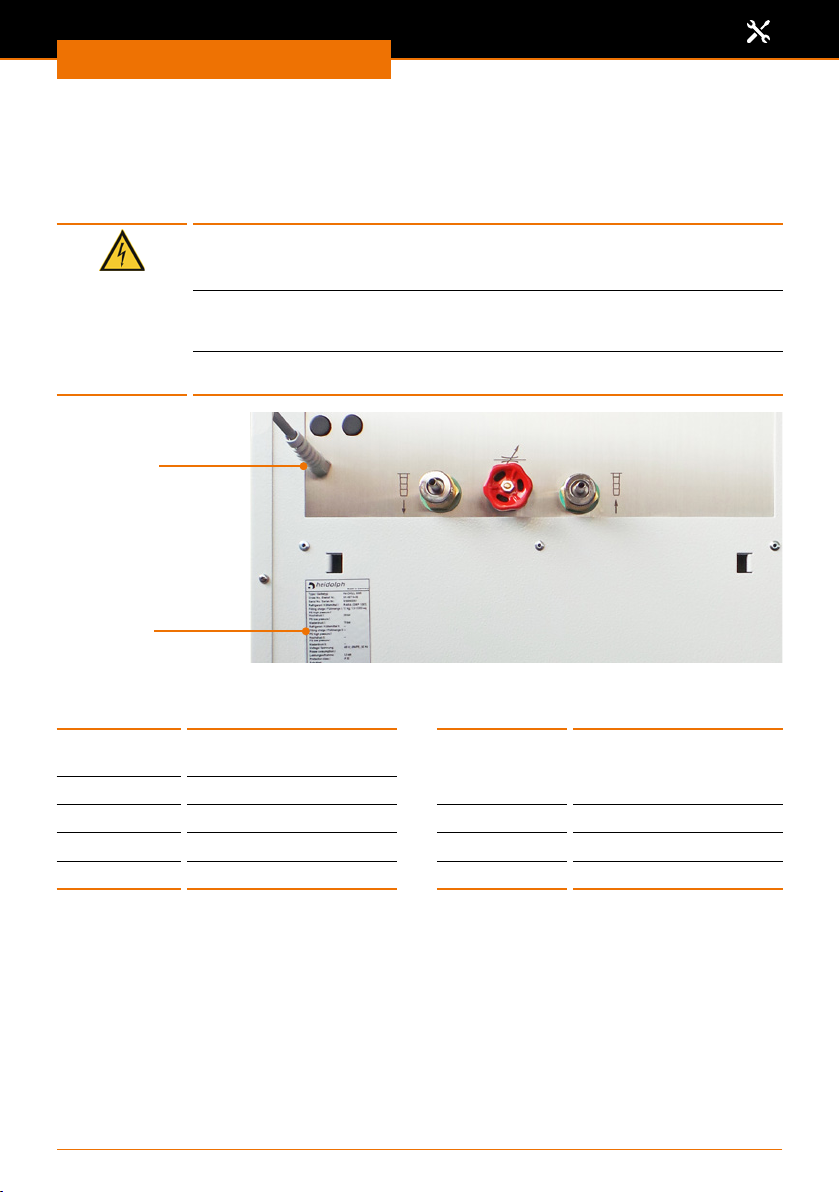
same. The rated voltage for the device can be found on the rating plate
on the rear of the device.
The device is supplied with a grounded power cord.
plug is replaced, the new plug must have a protective conductor!
Power cord
Rating plate
Color code for electrical connections:
1-phases 3-phases
GREEN/YEL-
LOW
BLUE N: Neutral conductor
BROWN P: Phase
PE: Protective conductor
(Earth)
Assembly
GREEN/YELLOW
BLUE N: Neutral conductor
BROWN P: Phase
BLACK P: Phase
GREY P: Phase
In case the original
PE: Protective conductor
(Earth)
The device is connected to the mains with the power cord supplied. The power connection
is located on the rear of the housing.
For countries where a dierent plug than the standard plug supplied is used:
▪ The plug supplied may only be changed by a professional electrician.
▪ If you wish to use an adapter, ensure that it is grounded and approved in accordance
with the local regulations.
▪ Wiring, adapter and plug must at least meet the electrical power stated on the rating
plate.
▪ Do not use extension cables.
46
Page 47
Assembly
Peripheral connections
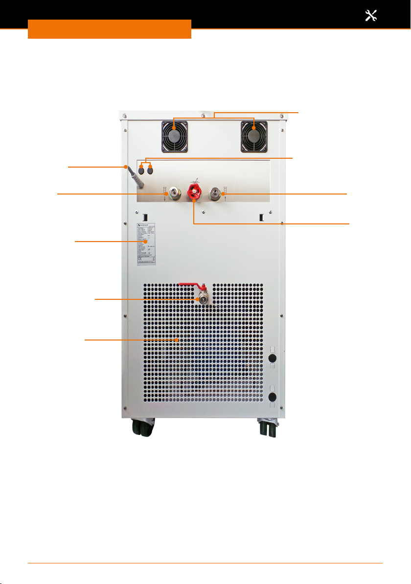
Overview of connections
Hei-CHILL 3000, Hei-CHILL 5000: Rear of device
Ventilation fans
Power cord
Pump connection
ow line
Rating plate
Emptying cock
Ventilation grille
Fuses VC 3000
Pump connection
return line
Adjusting wheel
Pressure adjustment
47
Page 48

Assembly
Temperature control hoses
Warning:
Risk of frostbite!
If you use unsuitable hoses at very low cooling temperatures, the
thermal uid may escape, and you could experience frostbite if you
come into contact with it.
Only use hoses with a temperature resistance that corresponds to
the operating temperature range of the device.
Warning:Risk of frostbite!
If you come into contact with cold hoses, you could experience frostbite if you are working with very low cooling temperatures.
Only use insulated hoses at operating temperatures < 0 °C.
All hose connections are located on the
top rear of the device.
▪ Pump ow line
▪ Pump return
All hose connections are tted with a
hose connector suitable for hoses with an
internal diameter of Ø 8 mm.
Carefully select hoses and connections for the chiller depending on the
uid, temperature and pressure of your application. (also see chapter
“Scope of delivery and accessories, Accessories”)
The user is responsible for any damage that results from improper
connections and the selection of unsuitable hoses.
Pump connection
return line
Pump connection
ow line
48
Page 49
Assembly
Connecting the chiller to an external consumer
Warning:
Risk of electric shock Risk of frostbite!
If the hoses between the chiller and the external consumer are not
leak-tight and connected without kinks, any escaping thermal uid
could result in frostbite and electric shock in the event of contact
with live components.
▪ Lay all hoses without kinks and protected against kinks.
▪ Check the leak-tightness of all hose connections and hoses.
▪ Secure all hoses against slippage.
▪ Maintain a clearance distance between hoses and power connec-
tions or live components.
Warning:Risk of explosion! Risk of frostbite! Risk of poisoning! Risk of injury! Risk of slipping!
If the hoses are improperly connected or glassware is exposed to
high pressure, the hoses and glassware could burst due to overpressure. The liquids that may then escape as a result pose a risk of
frostbite, poisoning and slippage. Burst glassware also poses a significant risk of injury and can result in exothermic reactions.
The maximum pressure at the outlet from the chiller is stated in
the Attachments (see chapter “Attachments, Technical data”). If
necessary, reduce the pressure in accordance with the connected
peripheral devices by tting a pressure regulator upstream at the
outlet from the chiller. Ensure that all hose connections are leak-tight
and secured against kinks and slippage to avoid overpressure.
If air penetrates into the external consumer and it is higher than
the chiller, it could cause the external circuit to empty into the
chiller when the pump is switched o. This could cause the chiller to
overow.
➜ Shorten the temperature control hoses as much as possible while ensuring that they
can be laid without any kinks and without any tension.
➜ Secure the temperature control hoses against slippage with the aid of hose clamps.
49
Page 50
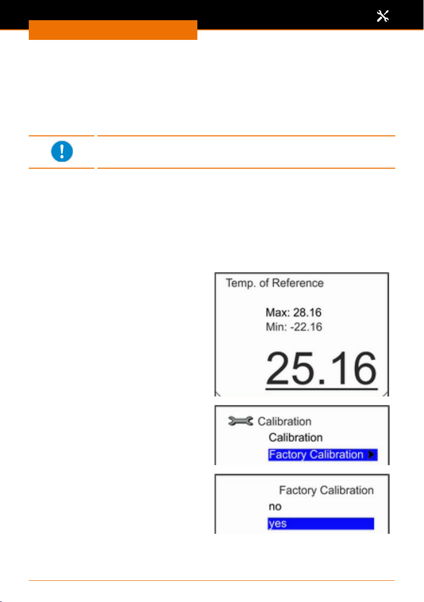
Assembly
Calibrating the temperature sensor
The internal thermometer in the device is precisely calibrated upon delivery.
If you detect a possible temperature deviation when checking the thermal uid using
a reference thermometer, the measurement values on the temperature sensor can be
adjusted.
For this purpose, the reference thermometer needs to be tted to the ow line on the
device.
The factory calibration is overwritten when adjusted. Only use a
reference thermometer with a high level of precision for the calibration
process.
✓ The chiller is switched o and disconnected from the power grid.
✓ Allow the device and thermal uid to warm up or cool down to room temperature.
➜ Attach a T-piece matching the inside hose diameter (Ø 8 mm) between the connection
for the pump ow line and your connection hose.
➜ Slide your reference thermometer into the still open end of the T-piece and attach the
thermometer.
✓ The calibrated reference thermometer has been installed in the ow line in a
process-capable manner.
Adjusting the temperature value.
✓ The device is switched on.
➜ Start the temperature control.
➜ Select the submenu “Setup” /
“Calibration” / “Calibration”.
➜ Use the arrow buttons to adjust the
displayed value to the temperature
of your reference thermometer and
conrm your changes using the button
“Select” .
Resetting the temperature value.
✓ The device is switched on.
➜ Select the submenu “Setup” /
“Calibration” / “Factory calibration”.
➜ Use the arrow buttons to select an
option and conrm your changes using
the button “Select”.
✓ Selecting the “no” option returns you
to the previous menu without changes.
✓ Selecting the “yes” option resets the
calibration to the factory setting.
50
Page 51
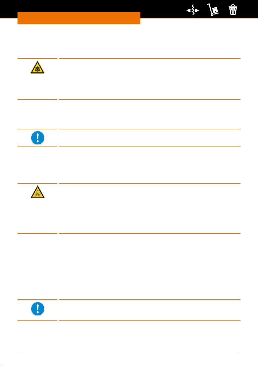
Disassembly and Storage
Dismantling, transportation and storage
Disassembly and Storage
Emptying the device
Warning! Risk of frostbite
You could experience frostbite if you come in contact with the thermal
uid while emptying it.
Switch o the device at an early stage before emptying it so that the
thermal uid can warm up to room temperature.Always wear protective gloves and protective clothing when emptying the device.
➜ Switch the device OFF.
➜ Allow the device and the thermal uid to cool down or warm up to room temperature.
➜ Position a container with sucient capacity directly underneath the drain screw.
The thermal uid will immediately ow out of the device when the
drain screw is opened.
➜ Turn the drain screw anticlockwise to open it.
➜ Observe the regulations for the disposal of used thermal uid (also see chapter
“Safety, Disposal”).
Emptying the refrigerant
Danger!: Risk of injury! Risk of poisoning! Environmental hazard!
The container of the cooling unit is under considerable pressure (19-28
bar) and contains environmentally harmful substances. Improper
emptying of the refrigerant could result in a serious risk of injury or
poisoning as well as environmental hazards.
The refrigerant in the internal cooling circuit may only be emptied by a
qualied refrigeration technician.
Transportation and storage
➜ Only store and transport the device and its components after emptying, cleaning and
dismantling it down to the basic device.
➜ When lifting the device, wear protective gloves and grip underneath the device.
➜ Store and transport the device and its components in the original packaging or in
another suitable container to prevent any damage.
➜ Carefully seal the packaging against any unauthorized or unintentional opening.
➜ Store the device in a dry and frost-free location.
Improper handling during storage and transport may result in damage
to the device and the mechanical components of the device.
Avoid jolts and vibrations when transporting the device.
51
Page 52
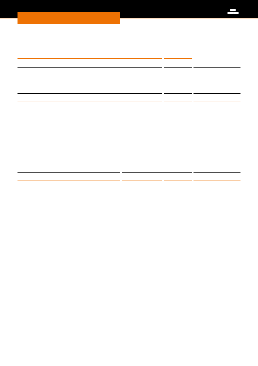
Accessories and Spare Parts
Scope of delivery
Component Quantity Order number
Hei-CHILL3000* 1 591-00700-00
Hei-CHILL 5000* 1 591-00700-01
Operating manual English /German 1 01-005-005-84
Warranty registration / conrmation of condition 1 01-006-002-78
EU Declaration of Conformity 1 01-001-025-17
*The product numbers are valid for 230 V devices in the European Community. Please contact Heidolph Instruments for
further product numbers on country specic varieties.
Accessories and Spare Parts
Accessories
Component
Tube with fabric reinforcement,
by the meter, not insulated,
maximum pump pressure < 16 bar
Thermal uid (20 L) - 30 to 90 1 569-00610-00
Additional accessories can be found in our general catalogue or at:
www.heidolph-instruments.com
Temperature
range °C
- 20 to 60 - 591-38000-00
Quantity Order number
52
Page 53
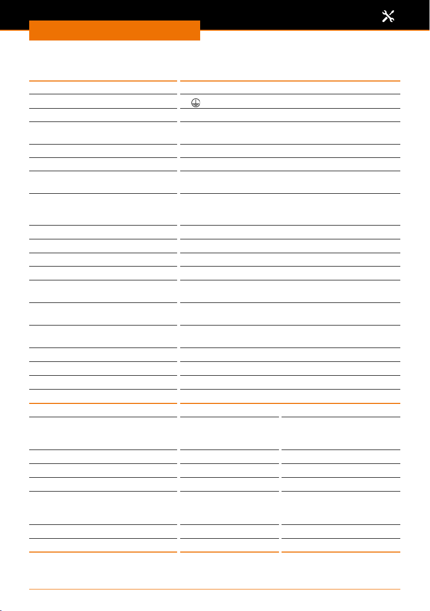
Assembly
Technical data
Overvoltage category II
Protection class (IEC 61140)
Protection class (IEC 60529) IP 32
Sound pressure level (dB(A))
(in accordance with IEC 61010)
Alarm output connection max. 30 V DC, 0.2 A
Contamination level 2
Distance to surroundings all
around (cm)
Classication according to
DIN 12876-1
(class/designation)
Display 3.5” TFT display (320 x 240 pixels)
Cooling Air-cooled
Refrigerant R-449A
Refrigerant ll weight max. (kg) 1,1
Thermal uid ll volume (max./
min. (L)
Max. ow rate (L at 1 bar, H2O
20°C)
Max. ow pressure (bar, H2O
20°C).
Operating temperature range (°C) -20 to 40
Temperature stability (K) ±0.05
Storage temperature range (°C) -20 to 50
Dimensions (W x D x H) (mm) 550 x 650 x 970
Model Hei-CHILL 3000 Hei-CHILL 5000
Standard supply voltage 1 x 230 V (50 Hz)
Cooling output (W) 3000 5000
GWP
CO2 equivalent (t) 1.3 1.5
Rated power 230 V 1800 W
Exhaust air m3/h 1300 2500
Weight (kg) 93 98
* Time horizon 100 years – according to IPCC IV
* 1397 1397
(100a)
Attachments
1
< 70
50
I/NFL
33/20
20
2
or
1 x 208 - 220 V (60 Hz)
208 - 220 V 2300 W
1 x 400 V 3/N/PE (50 Hz)
or
1 x 208 - 220 V 3/PE (60 Hz)
400 V 3300 W
208 - 220 V 3600 W
53
Page 54
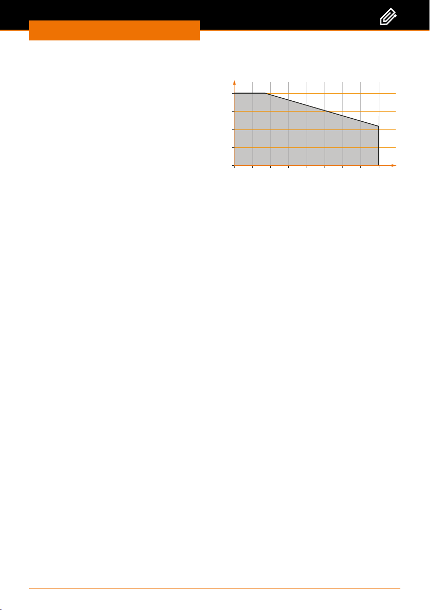
Attachments
Druck bar
52
Performance range
Hei-CHILL 3000
Hei-CHILL 5000
2,0
1,5
1,0
0,5
0,0
5101
Förderstrom L/Min
00
54
Page 55
Attachments
Thermal uids
Each individual thermal uid covers a recommended temperature range and must be
suitable for the temperature range for your application.
➜ Never use contaminated or degenerated thermal uid.
The thermal uid becomes more viscous at the lower limit of the
temperature range and inuences the temperature stability, pump
output and cooling output. Especially in water, ice may form that could
destroy the device. Vapours and odours may develop at the upper
limit of the range. Therefore, utilise the full temperature range only
when required.
Permissible recommended thermal uids
Heidolph desig-
nation *
Thermal uid Monoethylene
* Safety data sheets for the thermal uid can be requested at any time if required.
Chemical
designation
glycol / water
In the case of the Heidolph thermal uid, the water content will fall
after prolonged operation at high temperatures and the mixture will
become ammable (ash point 128 °C). Use a hydrometer to check
the mixing ratio.
Temperature
range in °C
-30 to 90 4 50
Viscosity (kin)
in mm²/s
(at 20 °C)
Viscosity (kin)
in mm²/s
at temperature
at -25 °C
Caution:
Damage to the device, damage to the environment
If water is used as the thermal uid, incorrect additives could damage
the device and also the environment if the additives escape from the
device.
Do not use the following thermal uids or additives under any circumstances:
▪ Distilled, deionised, fully demineralised water or sea water (due to
their corrosive properties)
▪ Water containing iron (due to rusting)
▪ Untreated river water (due to the formation of algae)
▪ Inorganic salts (due to occulation)
▪ Chlorine or ammonia as additives (e.g., in cleaning agents and disin-
fectants)
The following water is permissible as a thermal uid:
▪ Water free of impurities
▪ Water with a pH value between 6.0 and 8.5
▪ Ultra pure water and distilled water after the addition of 0.1 g
sodium carbonate (Na2CO3) per litre of water
The proportion of alkaline earth ions in the water must lie between
0.71 mmol/L and 1.42 mmol/L (corresponds to 4.0 and 8.0 °dH). Hard
water will cause limescale to develop in the device.
55
Page 56
Attachments
Cooling unit
Danger!: Risk of injury! Risk of poisoning! Environmental hazard!
The container of the cooling unit is under considerable pressure (19-28
bar) and contains environmentally harmful substances. Improper
emptying of the refrigerant could result in a serious risk of injury or
poisoning as well as environmental hazards.
The refrigerant in the internal cooling circuit may only be emptied by a
qualied refrigeration technician.
The compressor in the cooling unit is hermetically sealed and equipped with overload
protection that responds to the temperature and power consumption of the compressor.
The cooling unit contains refrigerant. Observe the special regulations
for its disposal (see also chapter “Safety, Disposal”).
Cooling output in kW at ambient temperatures in °C
Cooling output kW Hei-CHILL 3000 Hei-CHILL 5000
at 20 °C 3,00 5,00
at 10 °C 2,40 3,90
at 0 °C 1,68 2,75
at -10 °C 1,03 1,70
at -20 °C 0,60 1,00
* The cooling output is measured with the thermal uid maintained at a certain temperature. The ambient
temperature for the measurements is 20 °C.
Refrigerant and ll level
The cooling unit contains refrigerant. Observe the special regulations
for its disposal (see chapter “Safety, Disposal”).
The refrigerant R-449Acontains uorinated greenhouse gases.
The global warming potential (GWP) is 1430 at a time horizon of 100
years, CO2 equivalent = 1.0.
56
Page 57
Service
Contact / Technical Service
Questions / Repair work
If any aspect of installation, operation or maintenance remains unanswered in the
present manual, please get in touch with the following address.
For repairs please call Heidolph Instruments or your local authorized Heidolph
Instruments distributor.
Warning!
Danger of poisoning!
Contaminated devices can lead to severe injury or death of our
employees!
When shipping items for repair that may have been contaminated by
hazardous substances, please:
▪ advise exact substance
▪ take adequate protective action towards our parts receiving and
service personnel
▪ mark the pack in accordance with Ordinance on Hazardous
Substances
A “Conrmation of Condition” form can be found at the end of this operating manual.
➜ Prior to shipping the device for repair, complete a copy of this form and submit it in
advance.
Contact details:
Heidolph Instruments Germany
Heidolph Instruments GmbH & Co. KG
Technical Service
Walpersdorfer Str. 12
D-91126 Schwabach / Germany
Tel.: +49 – 9122 - 9920-74
Fax: +49 – 9122 - 9920-84
E-Mail: [email protected]
www.heidolph.com
Heidolph Instruments North America
Phone: 1-866-650-9604
E-mail: [email protected]
www.heidolphNA.com
Heidolph Instruments United Kingdom
Phone: 01799 - 5133-20
E-mail: [email protected]
www.heidolph-instruments.co.uk
All other countries
You will nd contact details of your local Heidolph distributor at
www.heidolph.com
Service
57
Page 58
Service
Warranty
Heidolph Instruments provides a 3 year warranty for the
products described here (excluding glass and wearing parts) if
you register using the warranty card enclosed or online
(www.heidolph.com). The warranty period begins with the
date of registration. The serial number is also valid without
registration.
This warranty covers material and manufacturing defects.
In the event of a material or manufacturing defect, the device shall be repaired or
replaced free of charge under the terms of the warranty.
Heidolph Instruments shall not assume liability for any damage incurred as a result of
improper handling or transport.
Warranty claim?
➜ Please notify Heidolph Instruments or your local Heidolph distributor if you wish to
make a warranty claim.
58
Page 59
Service
Conrmation of condition
➜ In the case of repair, copy and complete the Conrmation of condition orm and send
it to Heidolph Instruments.
1.
Details about the device
Product number
Serial number
Reason for repair
2.
Has the device been cleaned, decontaminated/sterilized?
Yes No
Is the device in a condition which does not represent any health threats for the sta
3.
of our service department?
Yes No
If not, which substances has the device
come into contact with?
4.
Legally binding declaration
The customer is aware of being legally liable to Heidolph
Instruments for any damages arising from incomplete and
incorrect information.
Date Signature
Company stamp
Please note
Sender information
The shipper is responsible for the return of the goods in well
packed condition, suitable for the mode of transport.
Name, rst name
Company
Department, research
group
Street
Zip code, city
Country
Phone
E-mail
59
Page 60

Original-Betriebsanleitung
InhaltsverzeichnisInhaltsverzeichnis
Zu diesem Dokument 62
Version und Varianten ....................................................................................... 62
Über dieses Handbuch .......................................................................................62
Symbole und Signalwörter .................................................................................63
Inhaltsverzeichnis
Sicherheitshinweise 64
Allgemeine Sicherheitshinweise ..........................................................................64
EU Konformitätserklärung ...........................................................................64
Bestimmungsgemäße Verwendung ...............................................................64
Installation ...............................................................................................65
Qualikation der Mitarbeiter ........................................................................65
Pichten des Betreibers .....................................................................................66
Aufstellort .................................................................................................66
Änderungen am Gerät ................................................................................66
Sicherheit des Personals .............................................................................66
Sicherheit während der Benutzung ......................................................................67
Entsorgung ......................................................................................................67
Gerätebeschreibung 68
Geräteübersicht................................................................................................68
Gesamtansicht Hei-CHILL 3000, Hei-CHILL 5000 ............................................68
Bedienfeld Hei-CHILL .................................................................................68
Inbetriebnahme 69
Gerät Aufstellen ...............................................................................................69
Netzkabel anschließen / lösen ............................................................................70
Gerät ein- und ausschalten ................................................................................70
Sprache einstellen ............................................................................................71
Temperierüssigkeit einfüllen .............................................................................72
Menü-Führung .................................................................................................74
Voreinstellungen ...............................................................................................75
Sprache einstellen .....................................................................................75
Temperaturgrenzwert einstellen ................................................................... 76
Temperatursollwert einstellen ...................................................................... 77
Datum und Uhrzeit einstellen ......................................................................78
Bedienung 79
Übersicht Menüstruktur .....................................................................................79
Temperieren ....................................................................................................81
Pumpendruck regulieren .............................................................................82
Sonderfunktionen .............................................................................................82
Stand-by-Betrieb und Autostart ...................................................................82
Betriebsart für Kälteaggregat einstellen ........................................................83
Sollwert-Oset einstellen ............................................................................84
Grundeinstellungen anpassen .............................................................................85
Page 61

Inhaltsverzeichnis
Regelparameter ................................................................................................87
Temperierung über Programme steuern ............................................................... 89
Programm erstellen ....................................................................................89
Programmdurchläufe festlegen ....................................................................90
Programm starten und beenden ...................................................................91
Gerätestatus ....................................................................................................92
Schnittstellen ...................................................................................................93
Alarmausgang anschließen ..........................................................................94
Werkseinstellung wiederherstellen ......................................................................95
Reinigung und Wartung 96
Reinigung ........................................................................................................96
Gerät reinigen ...........................................................................................96
Wartung ..........................................................................................................97
Instandhaltung ..........................................................................................97
Fehlerbehandlung 99
Störungen und deren Beseitigung .......................................................................99
Montage 104
Elektrischer Anschluss ..................................................................................... 104
Peripherie-Anschlüsse .....................................................................................105
Übersicht Anschlüsse ................................................................................ 105
Temperierschläuche ................................................................................. 106
Umlaufkühler an externen Verbraucher anschließen ...................................... 107
Temperaturfühler kalibrieren ..................................................................... 108
Demontage und Lagerung 109
Abbau, Transport und Lagerung ........................................................................ 109
Gerät entleeren ....................................................................................... 109
Transport und Lagerung ............................................................................ 109
Ersatzteile und Zubehör 110
Lieferumfang ................................................................................................. 110
Zubehör ........................................................................................................ 110
Anhang 111
Technische Daten ........................................................................................... 111
Leistungsbereich ...................................................................................... 112
Temperierüssigkeiten .............................................................................. 113
Kälteaggregat ......................................................................................... 114
Service 115
Kontakt / Technischer Service .......................................................................... 115
Garantieerklärung ........................................................................................... 116
Unbedenklichkeitserklärung ............................................................................. 117
Page 62
Zu diesem Dokument
Urheberschutz
Diese Anleitung ist urheberrechtlich geschützt und ausschließlich für den Käufer zur
internen Verwendung bestimmt.
Die Überlassung dieser Anleitung an Dritte, Vervielfältigungen in jeglicher Art und Form
– auch auszugsweise – sowie die Verwertung und/oder Mitteilung des Inhalts sind ohne
schriftliche Genehmigung des Herstellers nicht gestattet.
Zuwiderhandlungen verpichten zu Schadenersatz. Weitere Ansprüche bleiben
vorbehalten.
Zu diesem Dokument
Version und Varianten
Version
Diese Anleitung beschreibt Funktion, Betrieb und Bedienung der Umlaufkühler
Hei-CHILL 3000 und Hei-CHILL 5000.
Version Änderungsdatum
1.0 07/2018
Varianten
Das Gerät ist in verschiedenen Ausstattungsvarianten erhältlich. Bestimmte Merkmale
oder Funktionen sind nur in bestimmten Ausstattungsvarianten verfügbar. Die Varianten
sind in dieser Anleitung beschrieben.
Über dieses Handbuch
Diese Betriebsanleitung ist Bestandteil des hier beschriebenen Gerätes.
➜ Lesen Sie diese Betriebsanleitung sorgfältig durch und beachten
Sie alle Sicherheits- und Warnhinweise.
➜ Sorgen Sie dafür, dass jeder Benutzer des Gerätes vor
Inbetriebnahme die Betriebsanleitung sorgfältig gelesen hat.
➜ Bewahren Sie diese Betriebsanleitung so auf, dass sie jederzeit für
jeden Benutzer zugänglich ist.
➜ Geben Sie diese Betriebsanleitung an den Nachfolge-Besitzer
weiter.
Die aktuelle Version dieser Betriebsanleitung nden Sie auch unter:
https://heidolph-instruments.com/de/service/downloads/
betriebsanleitungen#Rotationsverdampfer/Umlaufkühler
(Hei-CHILL 3000-5000).
Beachten Sie darüber hinaus die örtlichen Bestimmungen am Aufstellort.
62
Page 63
Zu diesem Dokument
Symbole und Signalwörter
In dieser Betriebsanleitung werden standardisierte Symbole und Signalwörter verwendet,
um Sie vor Gefahren zu warnen oder Ihnen wichtige Hinweise zu geben. Beachten Sie
diese Hinweise unbedingt, um Unfälle und Schäden zu vermeiden.
Die folgenden Begrie und Grundsymbole werden verwendet:
Symbol Zusätzliche Signalwörter / Erläuterung
Warnzeichen
Verbots-
zeichen
Gebotszeichen
Weitere verwendete Zeichen:
Symbol Erläuterung
➜
✓
▪
Das gelbe Dreieck weist auf eine gefährliche Situation hin. Es wird in
Kombination mit den folgenden Signalwörtern verwendet:
GEFAHR:
Weist auf eine unmittelbar gefährliche Situation hin. Nichtbeachtung
führt zu schweren Verletzungen oder Tod.
WARNUNG:
Weist auf eine möglicherweise gefährliche Situation hin. Bei
Nichtbeachtung drohen schwere Verletzungen oder Tod.
VORSICHT:
Weist auf eine möglicherweise gefährliche Situation hin.
Nichtbeachtung führt zu Sachschäden und kann zu leichten bis mittelschweren Verletzungen führen.
Unbedingt vermeiden:
Der rote Kreis weist auf eine Situation hin, die unter allen Umständen
vermieden werden sollte. Bei Nichtbeachtung drohen schwere
Verletzungen oder Sachschäden.
Unbedingt beachten:
Der blaue Kreis weist auf eine wichtige Information hin. Bitte beachten
Sie diesen Hinweis, um Sachschäden zu vermeiden.
Bedienungsanweisung, Handeln erforderlich
Ergebnis der Handlung
Aufzählung von Informationen
▪
▪
a.
b.
c.
Aufzählung von Varianten
63
Page 64
Sicherheitshinweise
Allgemeine Sicherheitshinweise
Sicherheitshinweise
EU Konformitätserklärung
Das Gerät entspricht den folgenden EG-Richtlinien*:
▪ 2006/42/EG Maschinen-Richtlinie
▪ 2014/30/EU EMV-Richtlinie
*Siehe hierzu auch beigelegte „EU-Konformitätserklärung”.
Das Gerät ist nach dem Stand der Technik und den anerkannten sicherheitstechnischen
Regeln gebaut. Dennoch bestehen beim Installieren, Arbeiten und Instandhalten Gefahren.
➜ Betriebsanleitung bitte stets verfügbar halten.
Das Gerät darf nur unter folgenden Bedingungen benutzt werden:
➜ Betreiben Sie das Gerät nur, wenn es in technisch einwandfreiem Zustand ist.
➜ Betreiben Sie das Gerät nur, wenn Sie über das nötige Sicherheits- und
Gefahrenbewusstsein verfügen.
➜ Benutzen Sie das Gerät nur entsprechend den Vorschriften in dieser Betriebsanleitung.
➜ Wenn Informationen missverständlich sind oder Sie Informationen vermissen, fragen
Sie Ihren Vorgesetzten oder wenden Sie sich an den Hersteller.
➜ Bedienen Sie nichts an dem Gerät ohne Befugnis.
➜ Verwenden Sie das Gerät nur bestimmungsgemäß.
Bestimmungsgemäße Verwendung
Das Gerät darf nur von autorisiertem Fachpersonal betrieben werden.
Das Gerät ist für folgende
Verwendung geeignet:
Das Gerät darf
betrieben werden
in Forschungslabor,
Praktikum, und Produktion
von:
▪ Kühlen von Glaskühlern de Rotationsverdampfers:
Hei-VAP Industrial
▪ Temperieren und Fördern von nichtbrennbaren
Temperierüssigkeiten in einem geschlossenen Kreislauf
▪ Ökonomische Alternative zur Kühlung mit Leitungs wasser
▪ Chemie
▪ Pharmazie
▪ Biologie
▪ Umwelt-Analytik
▪ Grundlagenforschung
▪ Ähnliche Forschungslabore
Vorhersehbare Fehlanwendung
Eine andere als die bestimmungsgemäße Verwendung gilt als nicht bestimmungsgemäß.
Für hieraus resultierende Schäden haftet der Hersteller nicht. Das Risiko trägt allein der
Betreiber.
Unter anderem gelten die folgenden Verwendungen als vorhersehbare Fehlanwendung:
▪ Betrieb des Geräts ohne Temperierüssigkeit
▪ Falscher Anschluss von Schläuchen
▪ Aufstellen des Geräts auf tischähnlicher Oberäche
▪ Einstellen eines falschen Pumpendrucks
▪ Betreiben mit einem Glasreaktor ohne Überdruckregelung
▪ Kühlen von Lebensmitteln
64
Page 65

Bedienung
Installation
Elektrische Sicherheit
▪ Das Gerät darf nur angeschlossen werden, wenn die vorhandene Netzspannung mit
den Angaben auf dem Typenschild des Gerätes übereinstimmt.
▪ In der Hausinstallation muss ein RCD-Schutzschalter vorhanden sein, der das Gerät
im Fehlerfall vom Stromnetz trennt.
▪ Der Netzanschluss muss jederzeit leicht zugänglich sein.
▪ Reparaturen dürfen nur von einer durch Heidolph Instruments autorisierten
Elektrofachkraft durchgeführt werden.
▪ Betreiben Sie das Gerät niemals mit einem defekten Netzkabel.
▪ Schalten Sie das Gerät immer AUS und lösen Sie das Netzkabel, bevor eine Wartung
oder eine Reparatur durchgeführt wird.
Temperierüssigkeiten
▪ Das Gerät ist ausschließlich für nichtbrennbare Temperierüssigkeiten entsprechend
der Klassenbezeichnung I nach DIN 12876-1 ausgelegt.
▪ Temperierüssigkeiten decken jeweils einen bestimmten Temperaturbereich ab.
Die Temperierüssigkeit muss entsprechend der gewünschten Betriebstemperatur
ausgewählt und eingesetzt werden. Beim Über- oder Unterschreiten dieser
Temperaturbereiche können erhebliche Gefahren für Personal und Umwelt entstehen
(siehe auch Kapitel „Anhang, Technische Daten”, Abschnitt „Temperierüssigkeiten).
▪ Wir empfehlen die Verwendung von Heidolph-Temperierüssigkeit. Sie ist von
Heidolph Instruments getestet und freigegeben (siehe Kapitel „Ersatzteile und
Zubehör, Zubehör”).
▪ Zur bestimmungsgemäßen Verwendung muss das Sicherheitsdatenblatt der
Temperierüssigkeit beachtet werden.
Schläuche
▪ Beachten Sie bei der Auswahl der Schläuche für den Anschluss von Peripheriegeräten
neben der Beständigkeit zwingend den zulässige Temperaturbereich und den maximal
zulässige Druck.
▪ Wir empfehlen die Verwendung von Heidolph-Schläuchen. Diese sind vom Heidolph
Instruments getestet und freigegeben. (Siehe Kapitel „Ersatzteile und Zubehör,
Zubehör”.)
Qualikation der Mitarbeiter
▪ Das Gerät darf nur von geschultem Personal bedient werden.
▪ Das Gerät darf nur von Personen bedient werden, die durch geschultes Fachpersonal
in die ordnungsgemäße Bedienung eingewiesen und betreut werden.
▪ Das Gerät darf nur von Fachpersonal im gesetzlichen Mindestalter bedient werden.
▪ Andere Personen dürfen nur unter permanenter Aufsicht von erfahrenem und
geschultem Fachpersonal an dem Gerät arbeiten.
▪ Diese Betriebsanleitung muss von allen Personen gelesen und verstanden werden, die
mit diesem Gerät arbeiten.
▪ Das Personal muss eine Sicherheitseinweisung erhalten haben, die zu
verantwortungsvollem und sicherem Arbeiten führt.
65
Page 66
Sicherheitshinweise
Pichten des Betreibers
Aufstellort
▪ Das Gerät muss an einem geeigneten Platz aufgestellt werden.
▪ Das Gerät muss stabil und standsicher aufgestellt werden.
▪ Stellen Sie sicher, dass das Gerät und alle Gerätekomponenten und Anschlüsse
jederzeit frei zugängig sind.
▪ Alle Lüftungsgitter benötigen einen Mindestabstand von 50 cm zu Wänden oder
anderen vertikalen Flächen, damit eine freie Luftzirkulation gewährleistet ist.
▪ Innerhalb der Abstandsäche dürfen während des Betriebes keinerlei Gegenstände
wie Zubehör, Werkzeuge oder Chemikalien abgelegt oder gelagert werden.
▪ Alle Schraubverbindungen müssen sicher angezogen sein.
▪ Das Gerät darf nicht in der Nähe von leicht entzündlichen oder explosiven Stoen
betrieben werden.
▪ Betreiben Sie das Gerät (abhängig von den verwendeten Stoen) nur unter einem
geschlossenen belüfteten Abzug (siehe DIN EN 14175 und DIN 12924).
▪ Das Gerät darf nur innerhalb von geschlossenen Räumen und unter folgenden
Umgebungsbedingungen betrieben werden:
Umgebungstemperatur 5 - 31 °C bei 80 % relativer Luftfeuchtigkeit
32 - 40 °C linear abnehmend bis
maximal 50 % relativer Luftfeuchtigkeit
Aufstellhöhe 0 - 2.000 m über NN
Verschmutzungsgrad 2
Überspannungs-Kategorie II
▪ Wird das Gerät in korrosiven Atmosphären verwendet, sinkt die Lebensdauer des
Gerätes abhängig von Konzentration, Dauer und Häugkeit der korrosiven Umgebung.
Änderungen am Gerät
▪ Das Gerät darf nicht eigenmächtig umgebaut oder verändert werden.
▪ Bauen Sie keine Teile an oder ein, die nicht vom Hersteller zugelassen sind.
▪ Eigenmächtige Umbauten oder Veränderungen führen dazu, dass die
EU-Konformitäts erklärung des Geräts erlischt und das Gerät nicht mehr weiter
betrieben werden darf.
▪ Der Hersteller haftet nicht für Schäden, Gefahren oder Verletzungen, die durch
eigenmächtige Umbauten und Veränderungen oder durch Nichtbeachtung der
Vorschriften in dieser Anleitung entstehen.
Sicherheit des Personals
➜ Stellen Sie sicher, dass nur qualiziertes Fachpersonal und eingewiesene Mitarbeiter
das Gerät bedienen.
➜ Beachten Sie zur Vermeidung von Personen- und Sachschäden folgende Vorschriften:
- Labor-Richtlinie
- Unfallverhütungs-Vorschriften
- Gefahrsto-Verordnung
- Sonstige allgemein anerkannte Regeln der Sicherheitstechnik und Arbeitsmedizin
- Örtliche Bestimmungen
66
Page 67
Sicherheitshinweise
Sicherheit während der Benutzung
➜ Schützen Sie sich mit passender Kleidung, wenn Sie an dem Gerät arbeiten
(Schutzkleidung, Schutzbrille, Schutzhandschuhe).
➜ Verwenden Sie das Gerät nicht in explosionsgefährdeten Bereichen. Das Gerät ist
nicht explosionsgeschützt. Es verfügt über keinen Ex- oder ATEX-Schutz.
➜ Arbeiten Sie in der Umgebung des Gerätes nicht mit oener Flamme (Explosionsgefahr).
➜ Betreiben oder montieren Sie in der Nähe keine Geräte, welche Emissions- oder
Strahlungsquellen (elektromagnetische Wellen) für den Frequenzbereich (3*10
bis 3*1015 Hz) sind.
➜ Betreiben oder montieren Sie in der Nähe keine Geräte, welche Emissions- oder
Strahlungsquellen für ionisierende Wellen oder im Ultraschallbereich sind.
➜ Betreiben Sie das Gerät nicht, wenn adiabatische Kompression oder Stoßwellen
auftreten können (Druckwellenzündung).
➜ Schließen Sie alle Schlauchverbindungen prozesssicher an.
➜ Verlegen Sie alle Kabel und Schläuche knicksicher und außerhalb des Bedien- und
Gefahrenbereichs.
➜ Verschütten Sie keine Flüssigkeiten über das Gerät oder Teile davon.
➜ Wischen Sie evtl. auf das Gerät gelangte Flüssigkeiten sofort ab.
➜ Beheben Sie Fehler sofort.
➜ Vermeiden Sie unbeabsichtigten Druck auf das Display.
➜ Verwenden Sie keine scheuernden Mittel zur Reinigung; nur mit angefeuchteten
Tüchern abwischen.
➜ Schalten Sie das Gerät immer AUS, wenn es nicht in Betrieb ist.
11
Hz
Entsorgung
Kältemittel
Gerät und Verpackung
➜ Das Gerät darf nur durch qualiziertes Fachpersonal aus dem
Bereich Kältetechnik entsorgt werden.
➜ Entsorgen Sie das Kältemittel gemäß Verordnung 2015/2067/
EU in Verbindung mit Verordnung 517/2014/EU.
(Typ und Füllmenge des Kältemittels sind auf dem
Typenschild ersichtlich; siehe auch Kapitel „Anhang,
Technische Daten” Abschnitt „Kälteaggregat”.)
➜ Prüfen Sie die Geräte-Komponenten auf Gefahrenstoe und
Lösemittel.
➜ Reinigen Sie alle Komponenten, bevor sie entsorgt werden.
➜ Entsorgen Sie das Gerät entsprechend der nationalen gesetz-
lichen Richtlinien.
➜ Entsorgen Sie das Verpackungsmaterial entsprechend der
nationalen gesetzlichen Richtlinien.
67
Page 68
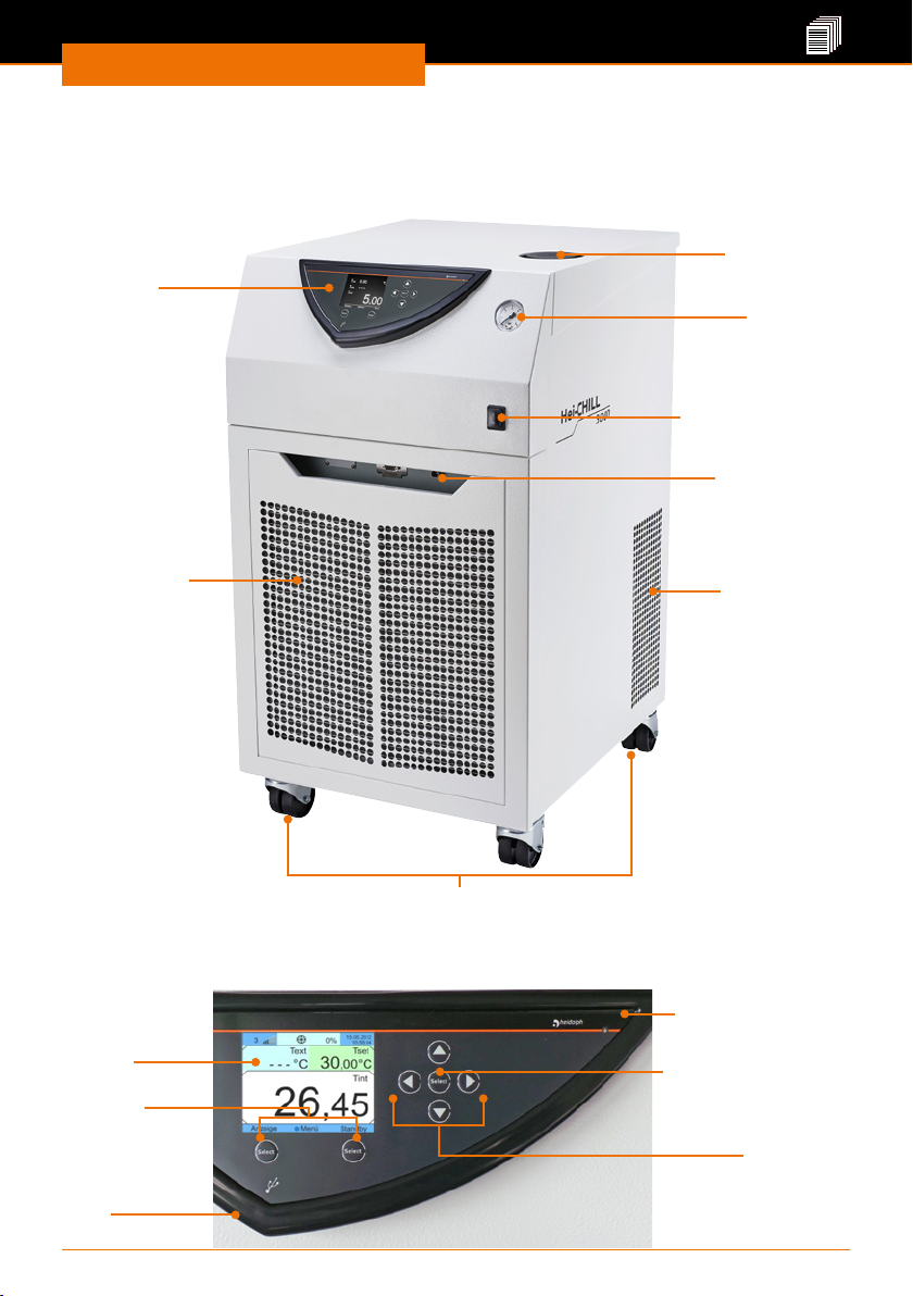
Gerätebeschreibung
Geräteübersicht
Gerätebeschreibung
Gesamtansicht Hei-CHILL 3000, Hei-CHILL 5000
Einfüllstutzen
Bedienfeld
Manometer
EIN-/AUS-Schalter
Schnittstelle
Alarmausgang
Frontblende mit
Lüftungsgitter
Lüftungsgitter
mit Deckel
4 Rollfüße, vorne mit Feststellbremse
Bedienfeld Hei-CHILL
Display
Softkeys:
angezeigte
Funktionen
steuern
USBSchnittstelle
Lichtsensor:steuert
Displayhelligkeit
Taste „Select” Select:
Display auswahl
bestätigen
Pfeiltasten:
im Display navigieren
68
Page 69
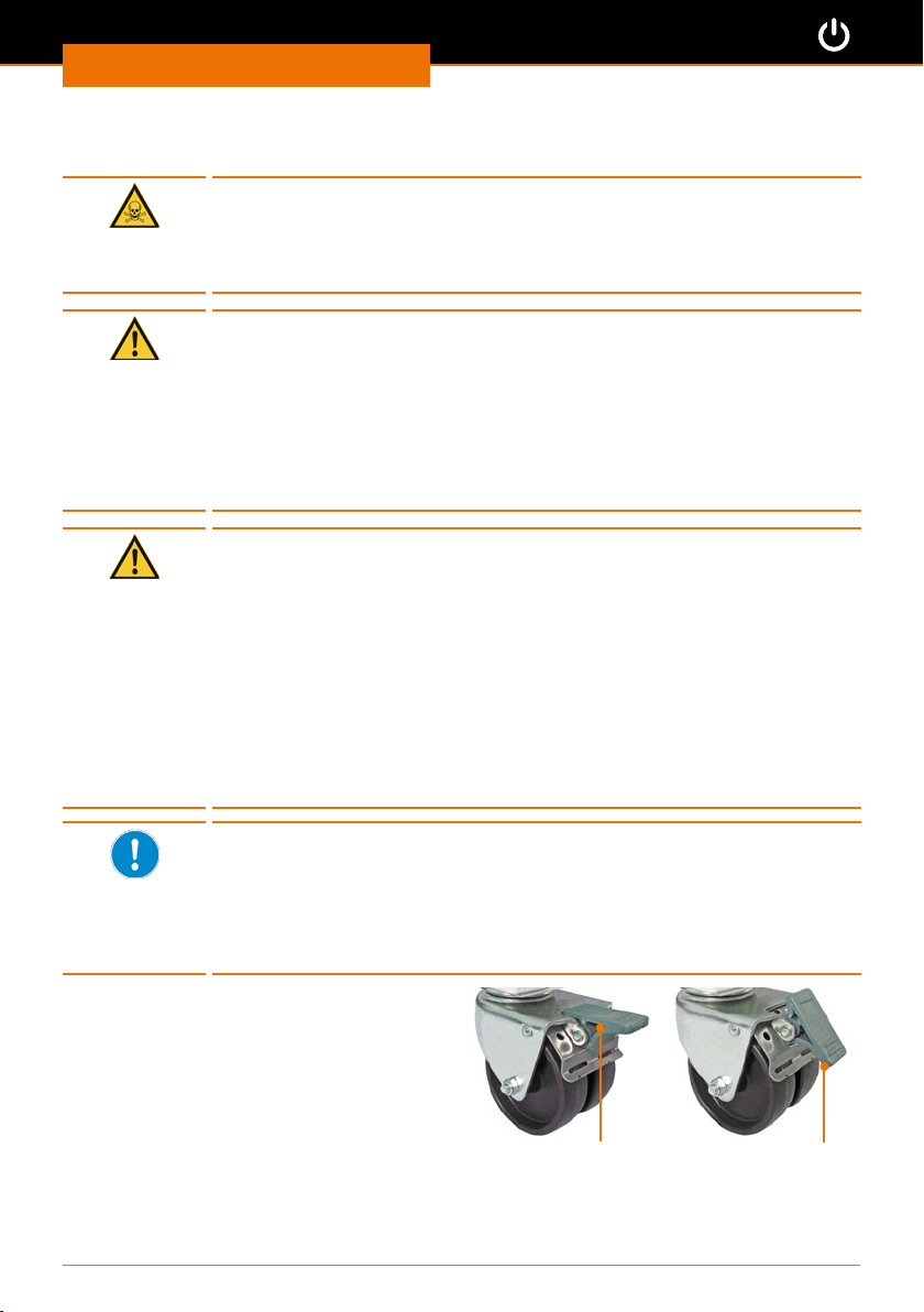
Inbetriebnahme
Gerät Aufstellen
Gefahr:
Vergiftungsgefahr!
Je nach verwendeter Temperierüssigkeit und Betriebsart können
toxische Dämpfe entstehen.
Sorgen Sie für ausreichende Absaugung der Dämpfe.
Warnung:
Quetschgefahr!
Die Kühlgeräte sind zur leichteren Beweglichkeit mit Rollen
ausgestattet. Dadurch kann das Gerät wegrollen und evtl. umstürzen.
Die Geräte dürfen nur auf dem Boden aufgestellt werden.
Stellen Sie das Gerät auf eine ebene, rutschfeste Fläche mit
ausreichender Tragfähigkeit!
Sichern Sie Geräte vor dem Wegrollen, indem Sie die Feststellbremse
arretieren!
Vorsicht:
Mögliche Beschädigung des Kühlsystems
Die Flüssigkeit aus dem Kompressor kann in das Zirkulationssystem
der Temperierüssigkeit gelangen, wenn das Gerät nicht in aufrechter
Position ist.
Das Gerät darf nicht gekippt werden. Stellen, bewegen und betreiben
Sie das Gerät nur in aufrechter Position.
Vorsicht:
Gerätebeschädigung
Bei unzureichender Luftzufuhr kann das Gerät überhitzen.
Halten Sie zum Lüftungsgitter einen Mindestabstand von 50 cm zu
Wänden oder anderen vertikalen Flächen ein
Inbetriebnahme
▪ Das Kühlgerät kann tiefer als die zu kühlende Apparatur aufgestellt
werden.
Beim Nachfüllen von Temperierüssigkeit muss in diesem Fall die
Pumpe eingeschaltet sein, und alle Schlauchanschlüsse müssen auf
Dichtigkeit geprüft sein, sonst kann Temperierüssigkeit aus-, bzw.
überlaufen.
▪ Sie können mehrere Geräte nebeneinander positionieren.
➜ Stellen Sie das Gerät auf einer
massiven glatten und temperaturbeständigen Fläche auf, die in Waage liegt.
➜ Lösen Sie die Feststellbremsen der
Rollen, indem Sie den Hebel nach oben
drücken.
➜ Arretieren Sie die Rollen des Geräts,
indem Sie den Hebel nach unten
drücken.
➜ Stellen Sie keine schweren Gegenstände auf dem Gerät ab.
➜ Reinigen Sie die Auageäche und die Rollfüße des Gerätes in regelmäßigen
Abständen.
Feststellbremse
gelöst
69
Feststellbremse
arretiert
Page 70
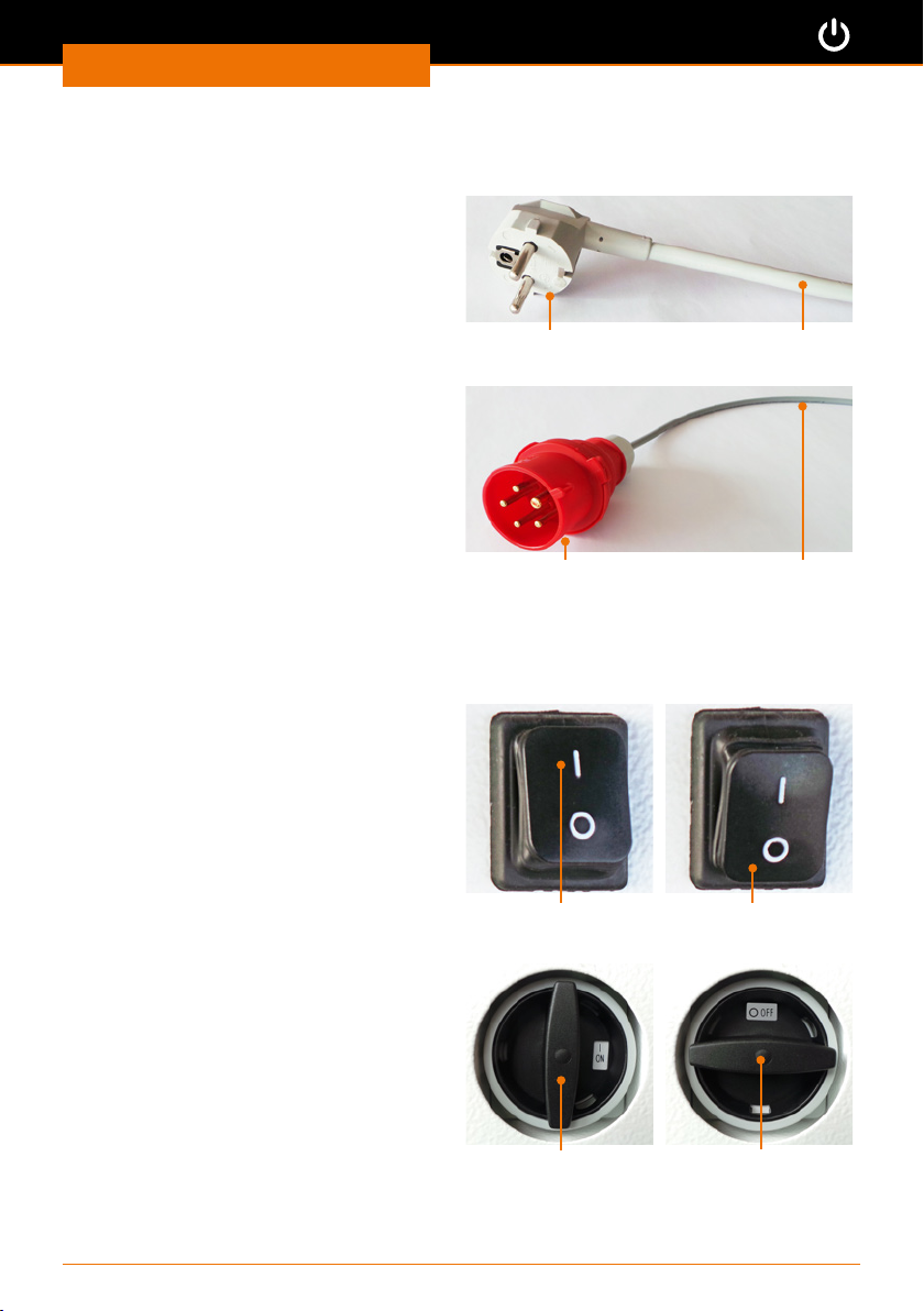
Inbetriebnahme
Netzkabel anschließen / lösen
Das Netzkabel ist fest mit dem Gerät
verbunden.
Der Anschluss bendet sich auf der
Rückseite des Gerätes.
✓ Der Hauptschalter ist AUS-geschaltet
bzw. steht auf „power o”.
➜ Verbinden Sie den Gerätestecker mit
Ihrer geerdeten Steckdose.
✓ Der Stecker ist sicher eingesteckt,
wenn er bis zum Anschlag einge-
schoben wurde.
➜ Lösen Sie den Gerätestecker, wenn das
Gerät nicht in Betrieb ist.
Gerätestecker
Gerät ein- und ausschalten
Hei-CHILL 3000
Gerät einschalten
➜ Drücken Sie den EIN-/AUS-Schalter
oben auf “I”.
✓ Das Gerät ist eingeschaltet.
Gerät ausschalten
➜ Drücken Sie den EIN-/AUS-Schalter
unten auf “O”.
✓ Das Gerät ist ausgeschaltet.
Ein-/Ausschalter: EIN
Hei-CHILL 5000
Gerät einschalten
➜ Drehen Sie den EIN-/AUS-Schalter im
Uhrzeigersinn auf “I”.
✓ Das Gerät ist eingeschaltet.
Gerät ausschalten
➜ Drehen Sie den EIN-/AUS-Schalter
gegen den Uhrzeigersinn auf “O”.
✓ Das Gerät ist ausgeschaltet.
Ein-/Ausschalter: EIN
Hei-CHILL 3000
Netzkabel
Hei-CHILL 5000
NetzkabelGerätetecker
Hei-CHILL 3000
Ein-/Ausschalter: Aus
Hei-CHILL 5000
Ein-/Ausschalter: Aus
70
Page 71
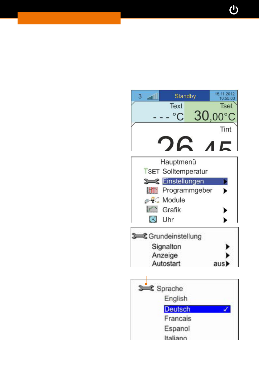
Inbetriebnahme
Sprache einstellen
➜ Schalten Sie das Gerät ein.
✓ Es ertönt ein Signalton.
✓ Beim ersten Einschalten wird automatisch das Untermenü „Befüllmodus” aufgerufen.
✓ Wenn das Untermenü „Befüllmodus” nicht in einer Sprache angezeigt wird, die für Sie
verständlich ist, muss als erstes die richtige Sprache eingestellt werden.
➜ Drücken Sie uf die Softkeytaste „ESC”.
✓ Sie erhalten das Grundmenü
angezeigt.
➜ Drücken Sie auf die Taste „Select”.
✓ Sie erhalten das Hauptmenü
angezeigt.
➜ Drücken Sie die Pfeiltaste ab
das Menü „Einstellungen” anzuwählen.
➜ Bestätigen Sie die Auswahl mit der
Taste „Select”.
✓ Sie erhalten das Menü „Einstellungen”
angezeigt.
➜ Drücken Sie die Pfeiltaste ab
um das Menü „Grundeinstellungen”
anzuwählen.
➜ Bestätigen Sie die Auswahl mit der
Taste „Select”.
✓ Sie erhalten das Menü
„Grundeinstellungen” angezeigt.
➜ Drücken Sie die Pfeiltaste ab
das Menü „Sprache” anzuwählen.
, um
ˇ
,
ˇ
, um
ˇ
Grundmenü
✓ Sie erhalten das Sprachmenü
angezeigt.
➜ Drücken Sie die Pfeiltaste auf
ab ˇ, um die gewünschte Sprache
auszuwählen.
➜ Drücken Sie auf die Taste „Select”,
um die ausgewählte Sprache zu
bestätigen.
➜ Drücken Sie den Softkey „ESC”.
✓ Sie kehren zurück zum Grundmenü.
oder
ˆ
Menü „Sprache”
71
Page 72
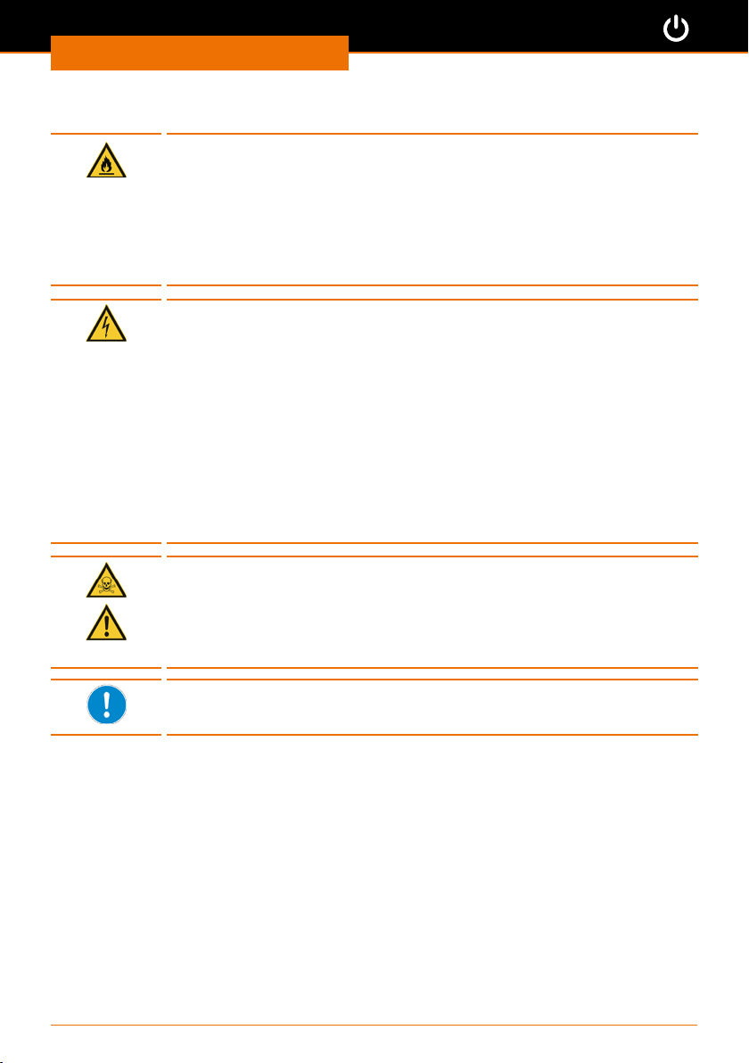
Inbetriebnahme
Temperierüssigkeit einfüllen
Gefahr:
Feuergefahr
Wenn Sie eine Temperierüssigkeit mit zu niedrigem Flammpunkt
einfüllen, kann diese unter Umständen Feuer fangen.
Verwenden Sie nur Temperierüssigkeit mit einem Flammpunkt, der
mindestens 20 K über dem Temperaturbereich der Anwendung liegt.
Verwenden Sie aufgrund der leichtentzündlichen Eigenschaft kein
Ethanol als Zusatzmittel.
Warnung:
Stromschlaggefahr
Bei Überfüllung kann überlaufende Temperierüssigkeit ins Gehäuse
dringen und zu einem Kurzschluss des Gerätes führen.
Stellen Sie sicher, dass das Gerät nicht überfüllt wird. Beachten Sie
unbedingt die Niveauanzeige sowie die thermische Volumenausdehnung
der Temperierüssigkeit.
Warnung:
Stromschlaggefahr
Bei unachtsamem Befüllen kann Temperierüssigkeit verspritzen, ins
Gehäuse dringen und zu einem Kurzschluss des Gerätes führen.
Verwenden Sie zum Befüllen einen Trichter. Vermeiden Sie das
Verspritzen von Temperierüssigkeit.
Warnung:
Vergiftungsgefahr! Verletzungsgefahr!
Wenn Sie mit chemisch aufbereiteten Temperiermitteln hantieren, können
Sie sich durch Spritzer Verletzungen an freien Hautstellen zuziehen.
Tragen Sie beim Befüllen des Umlaufkühlers immer eine Schutzbrille,
Schutzhandschuhe und Schutzkleidung.
Die Temperierüssigkeit von Heidolph ist für alle üblichen Anwendungen
geeignet. Sie deckt Temperaturbereiche von minus 30 °C bis plus 90 °C
ab. (Siehe Kapitel „Ersatzteile und Zubehör, Zubehör”)
72
Page 73
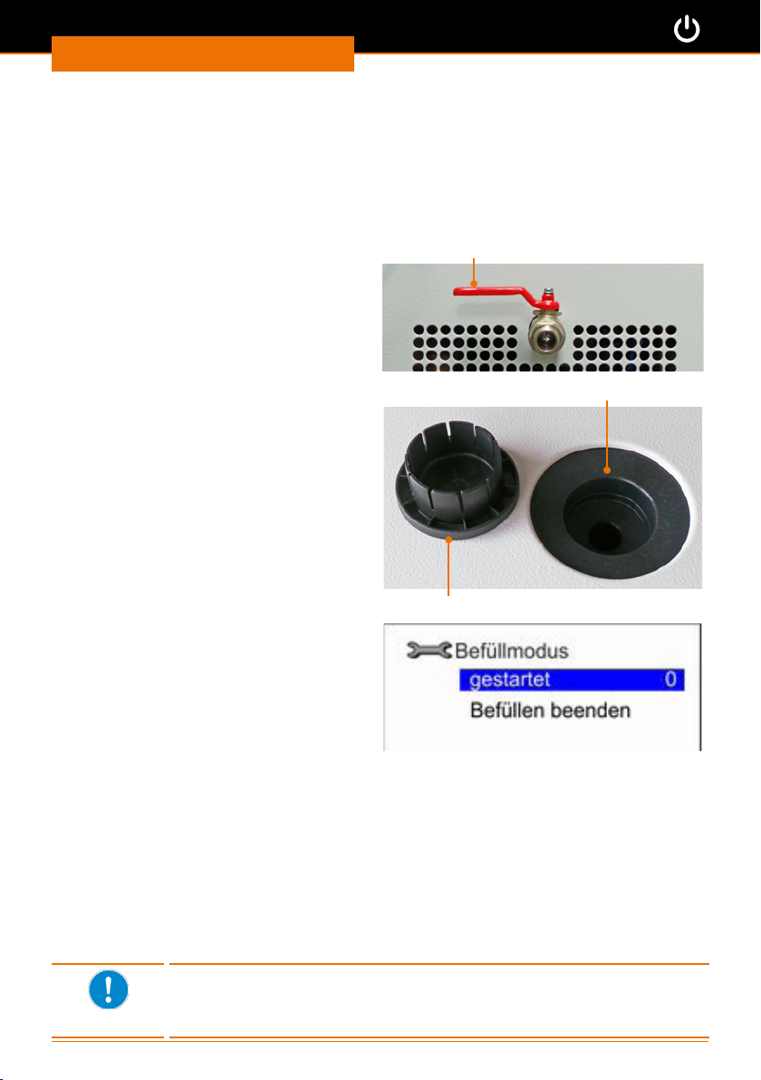
Inbetriebnahme
Erstbefüllung
Das Reservoir für die Temperierüssigkeit fasst zwischen 20 und 33 Liter (s. Kapitel
“Anhang, Technische Daten”).
Die Befüllung des Gerätes wird über ein Softwareprogramm unterstützt. Ist der Füllstand
zu niedrig:
▪ werden Pumpe und Kälteaggregat nicht gestartet
▪ wird automatisch der Befüllmodus gestartet.
➜ Schließen Sie den Entleerungshahn,
indem Sie den Hahn bis zum Anschlag
nach inks drehen.
Entleerungshahn geschlossen
✓ Das Gerät ist eingeschaltet.
✓ Im Display sehen Sie das Untermenü
„Befüllmodus”..
➜ Ziehen Sie den Deckel auf dem
Einfüllstutzen vorsichtig nach oben ab.
➜ Füllen Sie die Temperierüssigkeit mit
Hilfe eines Trichters vorsichtig in den
Einfüllstutzen.
Verschlusskappe Reservoir
✓ Im Display wird rechts neben
„gestartet” der Wert „0” als Füllstand
angezeigt.
➜ Beobachten Sie die Füllstandsanzeige.
➜ Wenn er Wert auf 4-5 gestiegen ist,
ertönt in Intervallen ein akkustisches
Signal.
✓ Das Gerät ist ausreichend befüllt.
➜ Schließen Sie Ihren externen Verbraucher an (siehe Kapitel “Montage,
Peripherieanschlüsse”).
➜ Drücken Sie den Softkey „Stand-by”, um den externen Verbraucher zu befüllen.
➜ Füllen Sie weiter Temperierüssigkeit nach, bis der Füllstand erneut auf den Wert 4-5
gestiegen ist und ein Signalton zu hören ist.
➜ Beenden Sie den Füllvorgang und schließen Sie das Reservoir mit dem Deckel.
➜ Drücken Sie die Pfeiltaste ab
➜ Verlassen Sie das Menü „Befüllmodus” mit dem Softkey „ESC”.
✓ Sie kehren zurück zum Grundmenü.
Die Intervalle zwischen den Signaltönen verkürzen sich bis zum
Dauerton, wenn der Füllvorgang nicht beendet wird. Bei Dauerton ist
das Gerät überfüllt und kann nicht gestartet werden. Vor dem Start der
Pumpe muss erst etwas Temperierüssigkeit abgelassen werden
, um „Befüllen beenden” anzuwählen.
ˇ
73
Einfüllstutzen Reservoir
Page 74
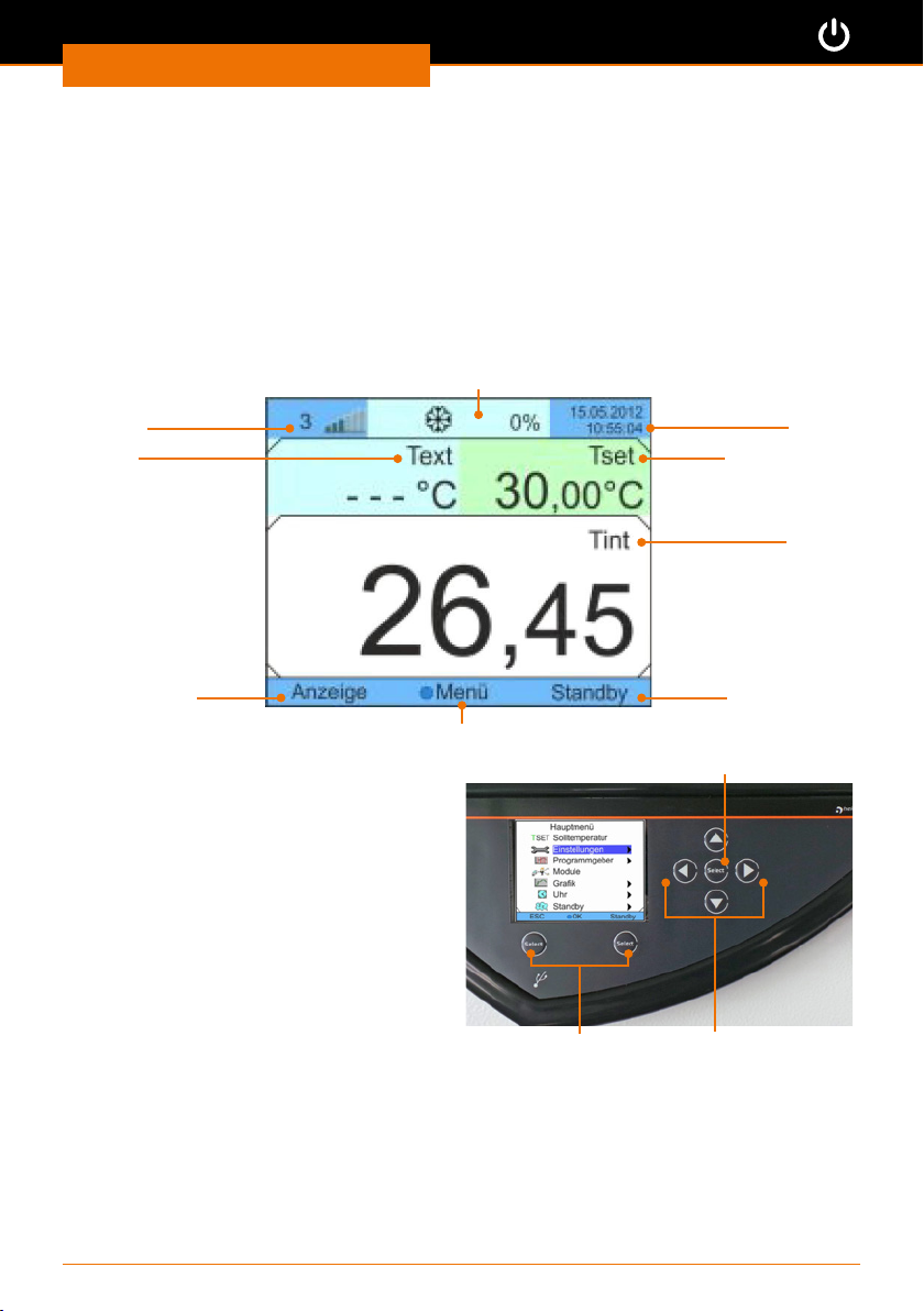
Inbetriebnahme
Menü-Führung
Vom Grundmenü gelangen Sie in das Hauptmenü, das in 6 Untermenüs gegliedert ist. Zu
manchen dieser Untermenüs gibt es bis zu 4 weitere Untermenüs.
(siehe folgendes Kapitel „Bedienung, Übersicht Menüstruktur”)
Grundmenü
➜ Schalten Sie das Gerät EIN.
✓ Es ertönt ein Signalton.
✓ Sie erhalten nach dem Begrüßungsbildschirm das Grundmenü angezeigt.
Aktuelle Leistung der Gesamtkälteleistung
Aktueller
Füllstand
Externe
Isttemperatur
Datum und
Uhrzeit
Solltemperatur
Interne
Isttemperatur
Aktuelle Belegung
Softkey rechts
Aktuelle Belegung der Taste „Select”
➜ Drücken Sie die Taste „Select”.
✓ Sie erhalten das Hauptmenü.
Hauptmenü
➜ Drücken Sie die Pfeiltaste auf p oder
ab q.
✓ Die verschiedenen Menüpunkte werden
ausgewählt und farbig hinterlegt.
✓ Ein Pfeil u hinter einem Menüpunkt
weist auf ein weiteres Untermenü hin.
➜ Drücken Sie die Taste „Select”, um ein
ausgewähltes Untermenü aufzurufen.
✓ Sie erhalten entweder ein weiteres
Untermenü oder den eingestellten Wert
zum aufgerufenen Parameter angezeigt.
Aktuelle Belegung
Softkey rechts
Taste „Select”
PfeiltastenSoftkeys
74
Page 75
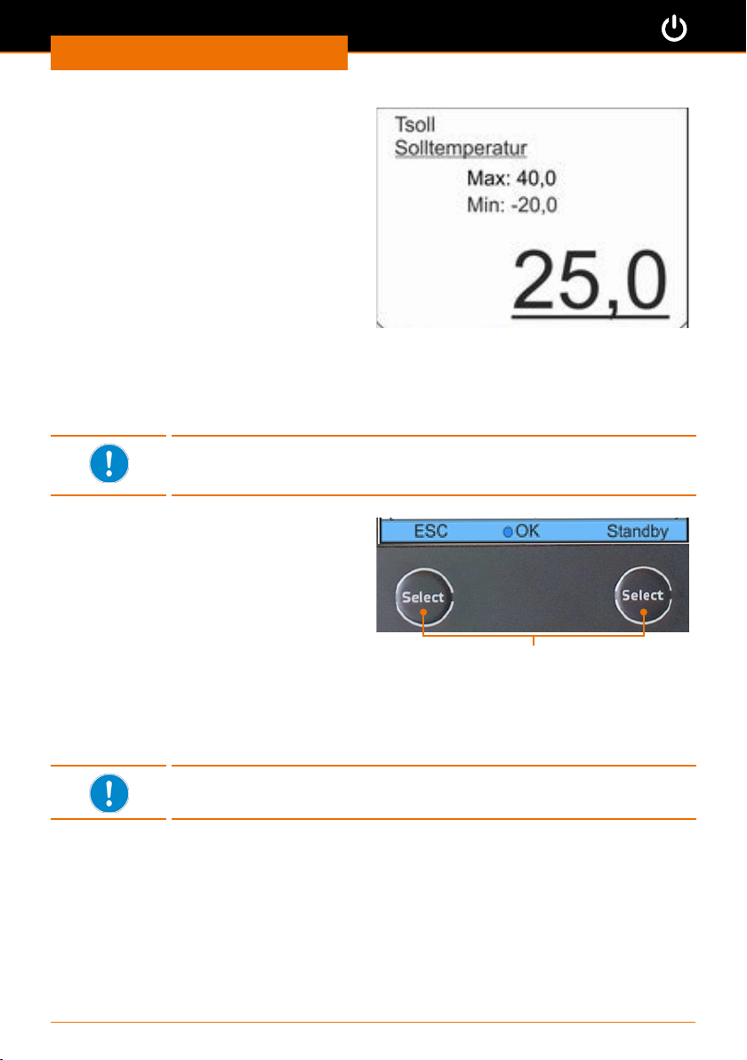
Inbetriebnahme
Untermenü zur Einstellung von Werten
✓ Unter dem aktuell eingestellten Wert
blinkt ein Cursor.
➜ Drücken Sie die Pfeiltasten rechts u
oder links t, um eine Zier
auszuwählen.
➜ Drücken Sie die Pfeiltaste auf p oder
ab q, um die Zier zu verändern.
➜ Drücken Sie die Pfeiltasten rechts u
oder links t, um die nächste Zier
auszuwählen.
➜ Bestätigen Sie den gesamten Wert mit
der Taste „Select”.
✓ Der eingestellte Wert wird gespeichert.
➜ Drücken Sie die Pfeiltasten links t, um zum vorherigen Menü zurückzukehren.
➜ Drücken Sie den linken Softkey unter „ESC”, um zum Grundmenü zurückzukehren.
Wenn Sie den Softkey „ESC” drücken, ohne vorher den Wert mit
der Taste „Select” zu bestätigen, werden die Änderungen nicht
übernommen.
Softkeys
Die Softkeys rufen immer die angezeigte
Funktion der darüberliegenden Fußzeile auf.
✓ Sie benden sich in einem Untermenü.
➜ Drücken Sie den linken Softkey „ESC”.
✓ Sie gelangen aus jedem Untermenü
direkt zum Grundmenü.
➜ Drücken Sie den rechten Softkey
„Standby”.
✓ Das Gerät wird aus jedem Menü
sofort in Standby-Modus oder in
Temperierbetrieb geschaltet.
Softkeys
Mit wenigen Ausnahmen sind die Softkeys in jedem Menü und
Untermenü mit den Funktionen „ESC” und „Standby” belegt.
75
Page 76
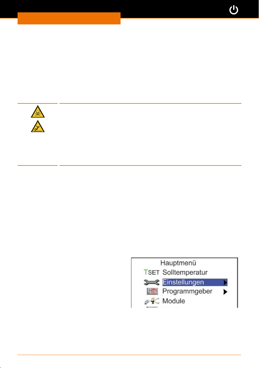
Inbetriebnahme
Voreinstellungen
Sprache einstellen
(Siehe Kaptel „Inbetriebnahme, Sprache einstellen”)
Temperaturgrenzwert einstellen
Bevor Sie den Umlaufkühler in Betrieb nehmen, muss die gewünschte Temperierung in
Abhängigkeit von der verwendeten Temperierüssigkeit eingestellt werden.
Warnung:
Vergiftungsgefahr! Verletzungsgefahr!
Temperierüssigkeiten decken jeweils einen bestimmten
Temperaturbereich ab. Beim Über- oder Unterschreiten dieser
Temperaturbereiche kann es zu Gerätebeschädigungen und zum
Auslaufen der Temperierüssigkeit kommen. Durch austretende
Temperierüssigkeit besteht Rutschgefahr und Vergiftungsgefahr.
Prüfen Sie den zulässigen Temperaturbereich Ihrer verwendeten
Temperierüssigkeit und stellen Sie die entsprechenden
Temperaturgrenzwerte sorgfältig ein.
Die Einhaltung der gewünschten Kühltemperatur legen Sie durch folgende zwei Variablen
fest:
▪ Temperaturgrenzwert:
Mit diesem Wert legen Sie den oberen bzw. unteren Maximalwert fest, der nicht
überschritten werden darf.
Sobald diese Werte über- oder unterschritten werden, ertönt ein Warnsignal.
▪ Temperatursollwert:
Mit diesem Wert stellen Sie die Kühltemperatur für die Temperierüssigkeit ein.
Bis dieser Temperatursollwert erreicht ist, schwingt die aktuelle Temperatur über
und unter diesen Sollert und bewegt sich dabei zwischen dem oberen und unteren
Temperaturgrenzwert.
Die beiden Werte für den Temperaturgrenzwert sind abhängig von der verwendeten
Temperierüssigkeit (siehe auch Kapitel „Ersatzteile und Zubehör, Ersatzteile”).
Oberen Temperaturgrenzwert
einstellen
✓ Das Gerät ist eingeschaltet.
➜ Wählen Sie im Hauptmenü den
Menüpunkt „Einstellungen”.
➜ Drücken Sie die Taste „Select”.
➜ Wählen Sie im Untermenü
„Einstellungen” den Menüpunkt „Temp.
Grenzwerte”.
76
Page 77
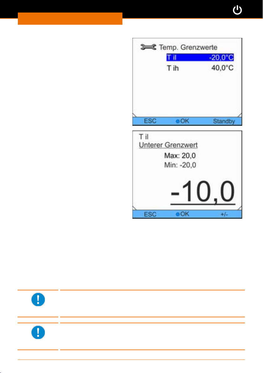
Inbetriebnahme
✓ Sie erhalten das Untermenü
„Temperaturgrenzwerte”.
➜ Drücken Sie die Pfeiltaste auf p oder
ab q, um den unteren Grenzwert
„Til” oder den oberen Grenzwert „Tih”
auszuwählen.
➜ Bestätigen Sie „Til” mit der Taste
„Select”.
✓ Sie erhalten das Untermenü „Unterer
Grenzwert”.
✓ Der Cursor blinkt unter dem einge-
tellten Wert.
➜ Korrigieren Sie den aktuell einge-
stellten Wert mit den Pfeiltasten
rechts u oder links t und auf p oder
ab q.
➜ Bestätigen Sie den gewünschten
gesamten Wert mit der Taste „Select”.
✓ Der eingestellte Wert wird gespeichert.
➜ Gehen Sie zurück zum Untermenü
„Temperaturgrenzwerte” mit der
Pfeiltasten links t.
➜ Drücken Sie den linken Softkey
unter „ESC”, um zum Grundmenü
zurückzukehren.
Oberen Temperaturgrenzwert einstellen
➜ Wiederholen Sie den Vorgang für den oberen Grenzwert
Temperatursollwert einstellen
Der einstellbare Sollwertbereich wird automatisch durch den
Temperaturgrenzwert eingeschränkt. Er kann maximal auf 2 °C
unter der oberen Temperaturgrenze sowie 2 °C über der unteren
Temperaturgrenze eingestellt werden..
Bei einem Temperatursollwert oder einer Ist-Temperatur < 5 °C
leuchtet die gelbe LED am Gerät. Sie warnt vor der evtl. inkorrekten
Verwendung einer Temperierüssigkeit und daraus folgenden Schäden
am Gerät.
77
Page 78
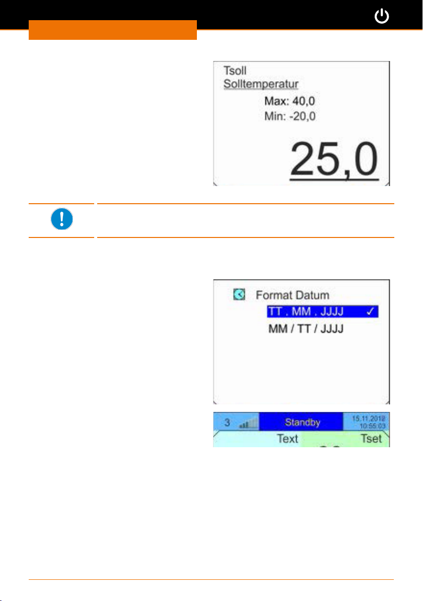
Inbetriebnahme
✓ Das Gerät ist eingeschaltet.
➜ Wählen Sie im Hauptmenü den
Menüpunkt „Solltemperatur”.
✓ Der Cursor blinkt unter dem einge-
tellten Wert.
➜ Geben Sie mit Hilfe der Pfeiltasten
den gewünschten Sollwert für die
Temperatur ein.
✓ Der Wert muss zwischen dem
angezeigten Werten „Max.” und „Min.”
liegen.
➜ Bestätigen Sie Ihre Auswahl mit der
Taste „Select”.
Liegt der eingegebene Sollwert außerhalb eines eingestellten
Temperaturgrenzwertes, ertönt ein Warnsignal. Der Wert wird nicht
übernommen.
Datum und Uhrzeit einstellen
✓ Das Gerät ist eingeschaltet.
➜ Wählen Sie das Untermenü „Uhr” /
„Uhrzeit/Datum stellen”.
➜ Geben Sie mit Hilfe der Pfeiltasten
die aktuelle Uhrzeit und das aktuelle
Datum ein und bestätigen Sie mit der
Taste „Select”.
➜ Stellen Sie im Untermenü „Format/
Datum” die gewünschte Darstellung für
das Datum ein.
✓ Datum und Uhrzeit werden oben
rechts im Grundmenü in der Kopfzeile
entsprechend Ihrer Einstellung
angezeigt.
78
Page 79
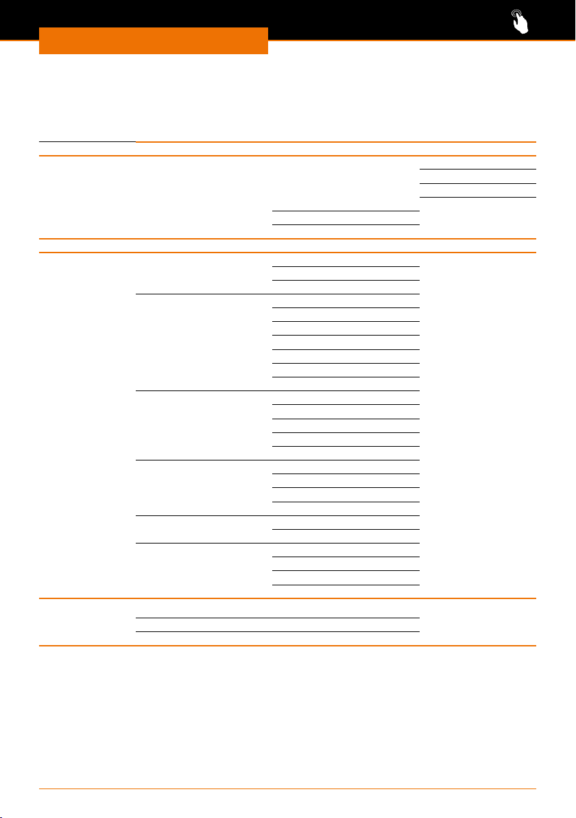
Bedienung
Übersicht Menüstruktur
Hauptmenü
Solltemperatur
Einstellungen (siehe Folgeseite)
Programmgeber Programm 1 - 5 Status Start
Module
Grak Modus Onlinegrak
Anzeige Messwerte Tset Tint Text
Aufz. Intervall 2 s (max.2h10min)
Zeitbereich automatisch
Zeitbasis absolut
Temperatur Skalierung automatisch
Temperat. Grenzwerte T-Skala Min. -13 °C
Uhr
Standby
Uhrzeit/Datum stellen
Format Datum TT.MM.JJJJ
Bedienung
Stop
Pause
Weiter
Editieren
Durchläufe
Aufzeichnung Start
Grak einfrieren Start
Tset Tint
Tset Text
Tint Text
Tint
Text
Tset
10 s (max.11h5min)
30 s (max.33h20min)
1 min (max.66h40min)
2 min. (max.133h)
9 min
45 min
2 h 15 min
relativ
manuell
T-Skal Max. 40 °C
MM.TT.JJJJ
79
Page 80
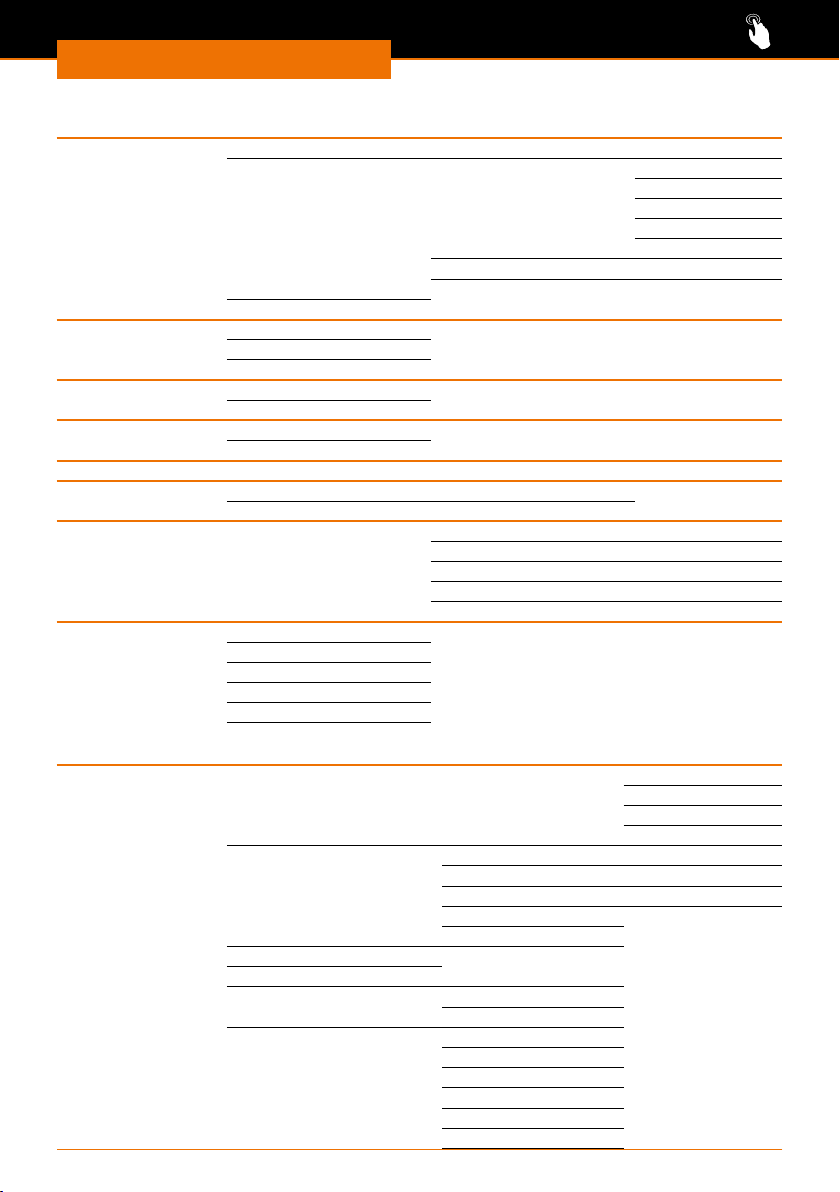
Bedienung
Menü Einstellungen
Regelung Regelgröße intern Pt 1000
Regelparameter intern Pt 1000 Xp
Sollwertoset Osetquelle aus
Korr.Größenbegr.
1
Kühlung autom. aus
ein
automatisch
Temp. Grenzwerte Unt. Grenzwert (Til)
Ob. Grenzwert ((Tih)
Befüllmodus Befüllen starten
Befüllen beenden
Grundeinstellung (siehe Folgeseite)
Kalibrierung Kalibrierung
Werkskalibrierung nein/ ja
Werkseinstellung Alles zurücksetzen nein/ja
Regelung Alles zurücksetzen nein/ja
Gerätestatus Fehlerspeicher
Gerätedaten
SW-Version
Typ ......................
Seriennummer
Di.Soll-/Istwert
50.0
Regelparam. intern nein/ja
intern Pt1000 nein/ja
sonstige Parameter nein/ja
2
0.0
Tn
Tv manuell/auto
Tv
Td
Menü Grundeinstellungen (Untermenü Einstellungen)
Grundeinstellungen Signalton Alarm laut
Warn. mittel
Fehler leise
aus
Anzeige Helligkeit automatisch
Stufe 5 ... 1
aus
Autostart aus aus
ein
Stromaufnahme 16.0A
Warnstufe Niveau 1
Alarmausgang: Standby Nur Alarme
Alarme und Standby
Sprache English
Deutsch
Francais
Español
Italiano
русский
80
Page 81
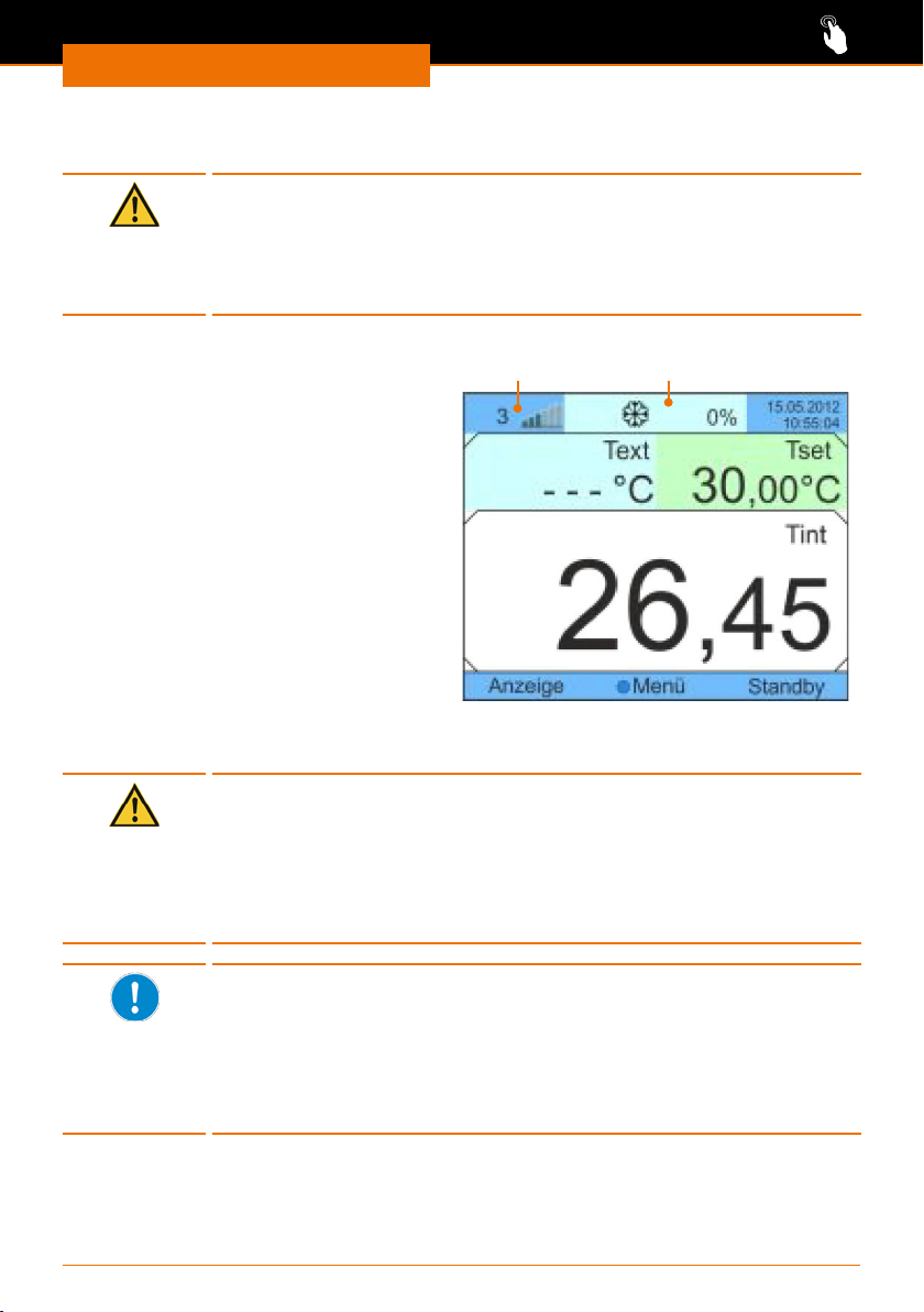
Bedienung
Temperieren
Vorsicht:
Mögliche Gerätebeschädigung
Wenn die Lüftungsönungen nicht frei sind, kann es zur Überhitzung
des Motors für Pumpe und Verdichter kommen.
Decken Sie die Lüftungsgitter niemals ab. Sorgen Sie immer für einen
Abstand von mindestens 50 cm zu Wänden oder anderen Geräten.
✓ Alle Peripheriegeräte sind sicher
angeschlossen und das Kühlmittel kann
ungehindert zirkulieren.
✓ Das Gerät ist mit Temperierüssigkeit
gefüllt
➜ Schalten Sie das Gerät EIN.
✓ Im Display wird as Grundmenü mit
der aktuellen Kühltemperatur „Tint”
angezeigt.
✓ Die Füllstandsanzeige der
Temperierüssigkeit liegt zwischen den
Werten 4 und 5.
➜ Drücken Sie auf den Softkey „Standby”.
✓ Die Pumpe für den Kreislauf der
Temperierüssigkeit wird gestartet.
✓ In der Kopfzeile wird „Standby” durch
die Anzeige der aktiven Kühlung ersetzt.
➜ Beobachten Sie die Füllstandsanzeige und füllen Sie gegebenenfalls
Temperierüssigkeit nach.
Vorsicht:
Mögliche Gerätebeschädigung
Wenn Sie den Umlaufkühler zum Kühlen im Bereich von
Minustemperaturen einsetzen, kann die Temperierüssigkeit gefrieren.
Wenn Sie das Gerät auf Minustemperaturen herunterkühlen möchten,
achten Sie auf die Verwendung der geeigneten Temperíerüssigkeit.
(Siehe auch Kapitel „Ersatzteile und Zubehör, Ersatzteile”)
Bei großem Temperaturunterschied zwischen Umlaufkühler und
externem Verbraucher kann es zu einem so hohen Temperaturgefälle
zwischen beiden Geräten kommen, dass die Kühlleistung nicht
aufrechterhalten werden kann.
Erhöhen bzw. senken Sie in diesem Fall die Solltemperatur der
Kühlung entsprechend oder sorgen Sie für ein geringeres zu kühlendes
Volumen in Ihrem externen Verbraucher.
Füllstandsanzeige
Grundmenü
Kühlung aktiv
81
Page 82
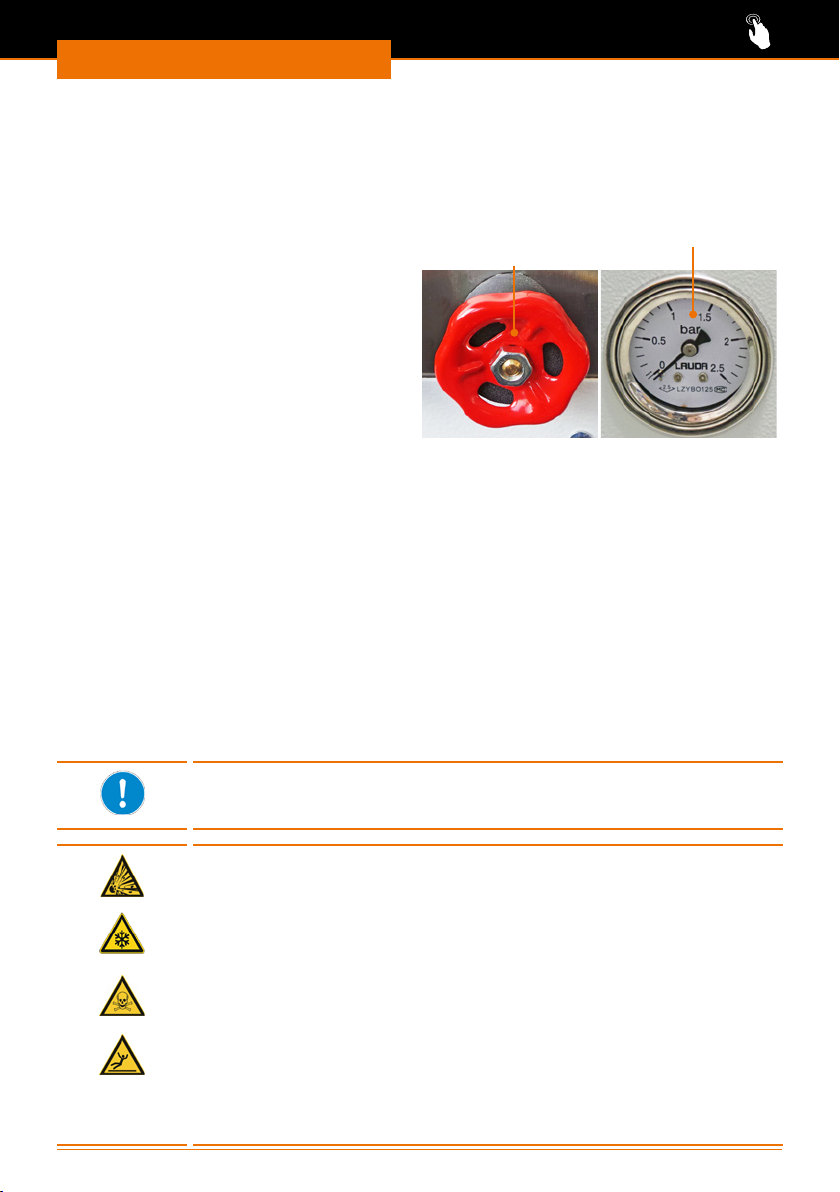
Bedienung
Pumpendruck regulieren
Auf der Geräterückseite bendet sich ein Stellrad. Mit diesem können Sie den Druck für
die Zirkulation der Tempereierüssigkeit entsprechend Ihrer Anwendung regulieren.
Der maximal erreichbare Druck beträgt 2 bar.
Den eingestellten Druck können Sie
am Manometer auf der Vorderseite des
Gerätes ablesen.
➜ Drehen Sie das Stellrad zur
Druckregulierung im Uhrzeigersinn.
✓ Der Pumpendruck wird erhöht.
➜ Drehen Sie das Stellrad zur
Druckregulierung gegen den
Uhrzeigersinn.
✓ Der Pumpendruck wird verringert.
✓ Im Manometer wird der Druck in bar
angezeigt.
Stellrad
Druckregulierung
Manometer
Sonderfunktionen
Stand-by-Betrieb und Autostart
Im Stand-by-Betrieb bendet sich das Gerät im Ruhezustand, wenn es eingeschaltet
wird. Alle Anzeigen am Display sind im Stand-by-Betrieb abrufbar.
Ist der Stand-by-Betrieb deaktiviert, bzw. der Autostart aktiviert und das Gerät enthält
ausreichend Temperierüssigkeit, beginnt das Gerät mit dem Einschalten sowie nach
einer Netzunterbrechung sofort zu kühlen.
Bei Auslieferung des Geräts ist der Stand-by-Betrieb aktiviert.
Wenn Sie das Gerät zum Kühlen des Rotationsverdampfers Hei-VAP
Industrial einsetzen, verändern Sie diese Einstellung nicht! Das
Kühlgerät wird über den Rotationsverdampfer ein- und ausgeschaltet.
Warnung:
Explosionsgefahr! Erfrierungsgefahr! Vergiftungsgefahr!
Verletzungsgefahr! Rutschgefahr!
Wenn das Gerät nach einer Netzunterbrechung automatisch wieder
den vollen Betrieb aufnimmt, können lose Schlauchverbindungen oder
defekte Glasgefäße zum unkontrollierten Austritt von Flüssikeiten
führen. Durch austretende Flüssigkeiten besteht Erfrierungsgefahr,
Vergiftungsgefahr und Rutschgefahr. Durch berstende Glassätze
besteht zusätzlich erhebliche Verletzungsgefahr und es kann zu
exothermen Reaktionen kommen.
Wenn Sie den Autostart aktivieren, lassen Sie den Umlaufkühler und
die angeschlossenen Peripheriegeräte auf keinen Fall unbeaufsichtigt.
Überprüfen Sie in regelmäßigen Abständen den sicheren Anschluß
der Schlauchverbindungen. Arbeiten Sie nur mit einwandfreien
Glasgefäßen.
82
Page 83
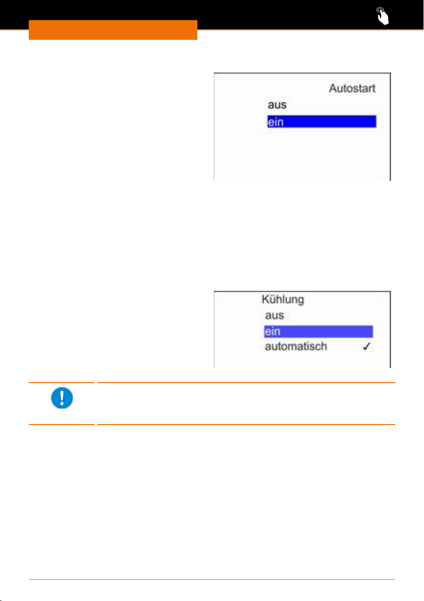
Bedienung
Autostart aktivieren und deaktivieren
✓ Das Gerät ist eingeschaltet.
➜ Wählen Sie das Untermenü
„Einstellungen” / „Grundeinstellungen”
/ „Autostart”.
➜ Wählen Sie mit Hilfe der Pfeiltasten
„ein” aus und bestätigen Sie Ihre
Auswahl mit der Taste „Select”.
✓ Der Autostart ist aktiviert.
➜ Zum Umstellen auf Stand-by-Betrieb
wählen Sie im Menü „Autostart” die
Option „aus”.
Betriebsart für Kälteaggregat einstellen
Das Kälteaggregat kann sowohl automatisch als auch manuell gesteuert werden.
Bei Auslieferung ist das Kälteaggregat auf „automatisch” eingestellt.
▪ „aus” deaktiviert das Kälteaggregat solange, bis es hier wieder aktiviert wird
▪ „ein” aktiviert das Kälteaggregat dauerhaft, bis eine andere Option gewählt wird
▪ „automatisch” schaltet das Kälteaggregat bei Bedarf automatisch aus und ein.
✓ Das Gerät ist eingeschaltet.
➜ Wählen Sie das Untermenü
„Einstellungen” / „Kühlung”.
➜ Wählen Sie mit Hilfe der Pfeiltasten
eine der angebotenen Optionen aus
und bestätigen Sie Ihre Auswahl mit
der Taste „Select”.
✓ Die geänderte Betriebsart ist aktiviert.
Die Vorlauftemperatur für die automatische Regelung des
Kälteaggregats beträgt ±2 K zum Sollwert. Bei bestimmten
Umgebungsbedingungen kann dies zu längeren Stillstandszeiten des
Kälteaggregats führen. Dies beeinträchtigt nicht die Kühlleistung.
83
Page 84
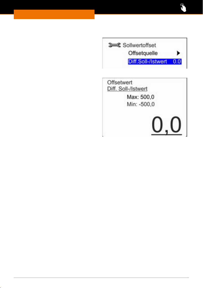
Bedienung
Sollwert-Oset einstellen
✓ Das Gerät ist eingeschaltet.
➜ Wählen Sie das Untermenü
„Einstellungen” / „Regelung” /
„Sollwertoset”.
➜ Wählen Sie mit Hilfe der Pfeiltasten
eine der angebotenen Optionen aus
und bestätigen Sie Ihre Auswahl mit
der Taste „Select”.
Dierenz Sollwert / Istwert
➜ Wählen Sie die Option „Di. Soll-/
Istwert”, um den oberen und unteren
Grenzwert für den Sollwertoset zu
bestimmen.
➜ Bestätigen Sie Ihre Änderungen mit
der Taste „Select”.
84
Page 85
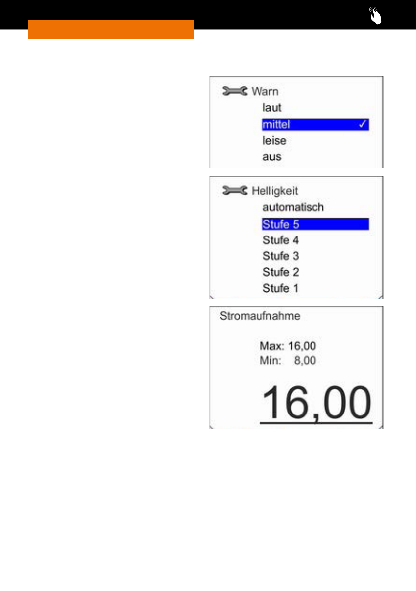
Bedienung
Grundeinstellungen anpassen
Lautstärke Signaltöne anpassen
✓ Das Gerät ist eingeschaltet.
➜ Wählen Sie das Untermenü
„Einstellungen” / „Grundeinstellungen”
/ „Signalton”.
➜ Wählen Sie mit Hilfe der Pfeiltasten
eine der angebotenen Optionen aus
und bestätigen Sie Ihre Auswahl mit
der Taste „Select”.
Helligkeit Display anpassen
✓ Das Gerät ist eingeschaltet.
➜ Wählen Sie das Untermenü
„Einstellungen” / „Grundeinstellungen”
/ „Anzeige” / „Helligkeit”.
➜ Wählen Sie mit Hilfe der Pfeiltasten
eine der angebotenen Optionen aus
und bestätigen Sie Ihre Auswahl mit
der Taste „Select”.
Stromaufnahme begrenzen
Wenn Ihre Netzabsicherung unter 16 A
liegt, kann die Stromaufnahme schrittweise von 16 A auf 8 A reduziert werden.
✓ Das Gerät ist eingeschaltet.
➜ Wählen Sie das Untermenü
„Einstellungen” / „Grundeinstellungen”
/ „Stromaufnahme”.
➜ Passen Sie mit Hilfe der Pfeiltasten die
Stromaufnahme an und bestätigen
Sie Ihre Änderungen mit der Taste
„Select”.
85
Page 86
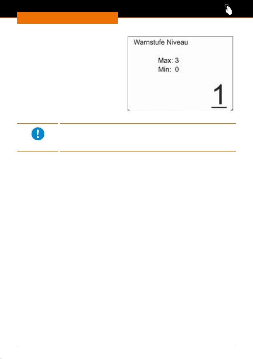
Bedienung
Warnstufe Minimalfüllstand festlegen
Bei Auslieferung ist das Gerät so konguriert, dass bei einem Füllniveau ab Stufe
2 eine Warnung für Unterniveau ausge-
geben wird. Diese untere Warnstufe kann
zwischen 0 und 3 angepasst werden.
✓ Das Gerät ist eingeschaltet.
➜ Wählen Sie das Untermenü
„Einstellungen” / „Grundeinstellungen”
/ „Warnstufe Niveau”.
➜ Passen Sie mit Hilfe der Pfeiltasten die
Warnstufe an und bestätigen Sie Ihre
Änderungen mit der Taste „Select”.
Wenn Sie die Warnstufe auf „0” festlegen, wird keinerlei Warnung
ausgegeben. Der Kühlbetrieb schaltet sich ab, sobald das unterste
Füllstandsniveau erreicht ist. Am Display wird eine entsprechend
Alarmmeldung angezeigt.
86
Page 87

Bedienung
Regelparameter
Die Regelparameter zur Kühlung des Gerätes sind bei Auslieferung auf eine Temperierüssigkeit mit Wasser eingestellt. Abhängig von der Applikation und der verwendeten
Temperierüssigkeit kann eine Anpassung der Regelparameter notwendig werden.
Durch die Viskositätsänderung der Temperierüssigkeit bei niedrigen Temperaturen
verschlechtert sich die Qualität der Regelung bei zunehmend tieferen Temperaturen.
D.h. wenn Sie z.B. mit einer üblichen Kühltemperatur von -20 °C arbeiten, sollten die
Regelparameter bei einer Betriebstemperatur von -10 °C justiert werden.
Beachten Sie dies bei der Einstellung der Regelparameter.
Interne Regelparameter
Die internen Regelparameter vergleichen die interne Solltemperatur mit der
Vorlauftemperatur. Diese Berechnung ergibt die Stellgröße, mit der gekühlt wird.
Parameter Bezeichnung Erläuterung Einheit
Xp
Tn
Tv
Proportionalbereich Gibt den Temperaturbereich an, in dem
der Proportionalanteil (P-Anteil) des
Reglers 0 ... 100 % der maximalen
Stellgröße beträgt.
Beträgt z. B. bei einem eingestellten Xp
von 10 K die Regelabweichung 2 K, so
beträgt der P-Anteil 20 % der Stellgröße.
Bei einer Regelabweichung von 10 K und
mehr beträgt der P-Anteil 100 % der
Stellgröße.
Nachstellzeit Ist für den Integralanteil (I-Anteil) der
Stellgröße maßgebend. Sie gibt das
Intervall an, in dem eine bestehende
Regelabweichung auntegriert wird.
Je größer Tn ist, desto langsamer wird
die Regelabweichung auntegriert. Somit
wird die Regelung träger. Ein kleineres
Tn macht die Regelung dynamischer und
führt schließlich zu Schwingungen.
Vorhaltezeit Hieraus wird der Dierentialanteil
(D-Anteil) der Stellgröße
gebildet. Er beeinusst die
Annäherungsgeschwindigkeit des Istwerts
an den Sollwert und wirkt dem P- und
I-Anteil entgegen.
Je größer die Vorhaltezeit Tv eingestellt
ist, desto stärker wird das Ausgangssignal
gedämpft. Als Faustformel gilt:
Tv = Tn x 0,75.
K
s
s
87
Page 88
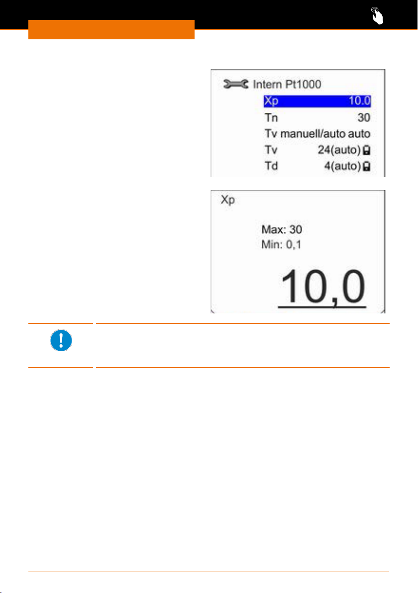
Bedienung
Interne Regelparameter anpassen
✓ Das Gerät ist eingeschaltet.
➜ Wählen Sie das Untermenü
„Einstellungen” / „Regelung” /
„Regelparameter”/„Intern Pt1000”.
➜ Wählen Sie mit Hilfe der Pfeiltasten
eine der angebotenen Optionen aus
und bestätigen Sie Ihre Auswahl mit
der Taste „Select”.
✓ Mit der Auswahl von „Tv manuell/auto”
können Sie die Option einer automa-
tische oder einer manuellen Regelung
bestimmen.
✓ Mit der Auswahl aller anderen
Optionen erhalten Sie die Möglichkeit,
die hinterlegten Werte anzupassen.
✓ Bestätigen Sie den geänderten Wert
mit der Taste „Select”.
Wenn der Regelparameter „Tv manuell/auto” auf automatische
Regelung eingestellt ist, werden die nachfolgenden Parameter „Tv”
und „Td” durch Faktoren aus Tn abgeleitet. Sie sind für Änderungen
gesperrt und durch ein Schloss-Symbol gekennzeichnet.
88
Page 89
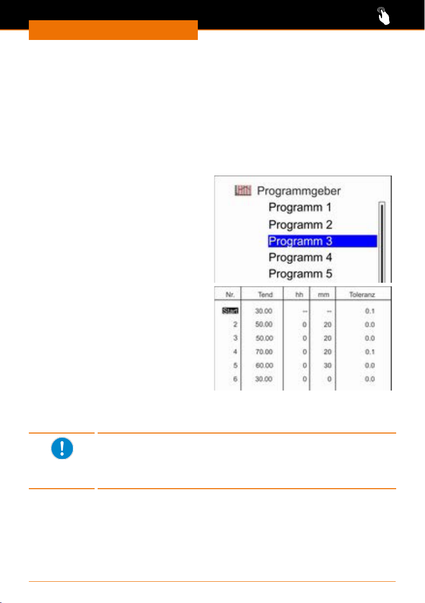
Bedienung
Temperierung über Programme steuern
Im Untermenü „Programmgeber” haben Sie die Möglichkeit, den Verlauf einer
Temperierung über eine denierte Zeitspanne festzulegen und zu speichern.
Sie können bis zu 5 verschiedene Programmabläufe speichern. Je Programm sind bis zu
150 Einzelschritte programmierbar.
Jedes der 5 Programme können Sie wiederum zwischen 1 bis 250 mal wiederholen lassen
oder Sie lassen es im Dauerbetrieb durchlaufen.
Programm erstellen
✓ Das Gerät ist eingeschaltet.
➜ Wählen Sie das Untermenü
„Programmgeber”.
➜ Wählen Sie eins der 5 Programme
„Programm n” aus.
➜ Wählen Sie den Menüpunkt „Editieren”.
➜ Zur Bearbeitung bestätigen Sie die
erste Zeile mit der Taste „Select”.
➜ Geben Sie mit Hilfe der Pfeiltasten je
Zeile folgende Werte ein:
▪ “Tend” die gewünschte Endtemperatur
▪ “hh” die gewünschte Stundenzahl
▪ “mm” die gewünschte Minutenzahl
▪ “Toleranz” die zulässige Abweichung
zu “Tend”.
➜ Bestätigen Sie jede neue Zeile mit der
Taste „Select”, um sie bearbeiten zu
können.
➜ Bestätigen Sie Ihre Änderungen mit der
Taste „Select”.
In der ersten Programmzeile kann keine Zeit „hh” und „mm”
eingegeben werden. Die hier eingegebene Temperatur wird so schnell
wie möglich angefahren.
Sobald die vorgegebene Temperatur erreicht ist, wird die nächste
Programmzeile abgearbeitet.
Programmparameter ändern
➜ Rufen Sie das gewünschte Programm auf.
➜ Wählen Sie mit Hilfe der Pfeiltasten einen zu ändernden Programmparameter auf.
➜ Bestätigen Sie den Parameter mit der Taste „Select” und ändern Sie den Wert.
➜ Ändern Sie gegebenenfalls weitere Parameter.und bestätigen Sie alle Änderungen mit
der Taste „Select”.
➜ Verlassen Sie das Programm mit der Pfeiltaste links.
89
Page 90
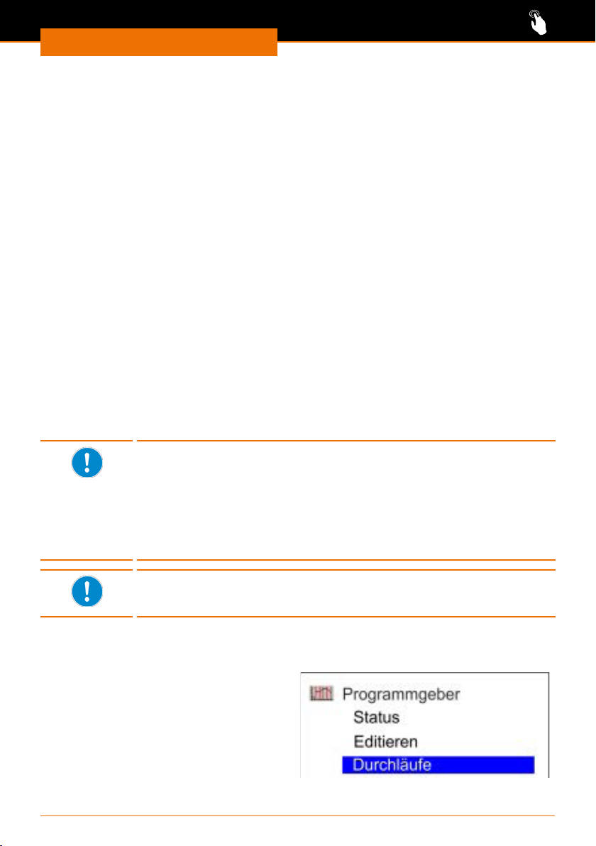
Bedienung
Programmzeile einfügen
➜ Rufen Sie das gewünschte Programm auf.
➜ Wählen Sie mit Hilfe der Pfeiltasten eine zu ändernden Programmzeile auf.
➜ Bestätigen Sie die Zeilen-Nummer mit der Taste „Select”.
✓ Unterhalb der Zeile wird eine freie Programmzeile eingefügt.
Programmzeile löschen
➜ Rufen Sie das gewünschte Programm auf.
➜ Wählen Sie mit Hilfe der Pfeiltasten die zu löschende Programmzeile auf.
➜ Bestätigen Sie die Zeilen-Nummer mit dem Softkey „lösch”.
✓ Die Zeile wird aus dem Programm entfernt.
Laufendes Programm ändern
✓ Sie benden sich im Grundmenü.
✓ Drücken Sie den Softkey „„Prog.x/y”.
➜ Wählen Sie mit Hilfe der Pfeiltasten einen zu ändernden Programmparameter auf.
✓ Ganze Programmzeilen können im laufenden Betrieb nicht eingefügt oder gelöscht
werden.
➜ Bestätigen Sie den gewünschten Parameter mit der Taste „Select” und ändern Sie den
Wert.
➜ Ändern Sie gegebenenfalls weitere Parameter.und bestätigen Sie alle Änderungen mit
der Taste „Select”.
➜ Verlassen Sie das Programm mit em Softkey „ESC”.
Je kleiner die zulässige Toleranz programmiert wird, desto genauer
ist die Einhaltung der gewünschten Temperatur. Da bis zum Erreichen
einer Temperatur jedoch eine gewisse Zeit erforderlich ist, kann es bei
knappen Zeitangaben zu unerwünschten Verzögerungen kommen, da
der nächste Programmschritt erst nach Erreichen der gewünschten
Temperatur abgearbeitet wird.
Bei großen Temperatursprüngen und kurzen Zeitvorgaben sollte also
eine größere Toleranz zugelassen werden.
Die Dauer eines einzelnen Programmschrittes kann maximal 999
Stunden und 59 Minuten betragen. Längere Zeiten müssten auf
mehrere Programmschritte verteilt werden.
Programmdurchläufe festlegen
✓ Das Gerät ist eingeschaltet.
➜ Wählen Sie das Untermenü
„Programmgeber”.
➜ Wählen Sie eins der 5 Programme
„Programm n” aus.
➜ Wählen Sie den Menüpunkt
„Durchläufe”.
90
Page 91
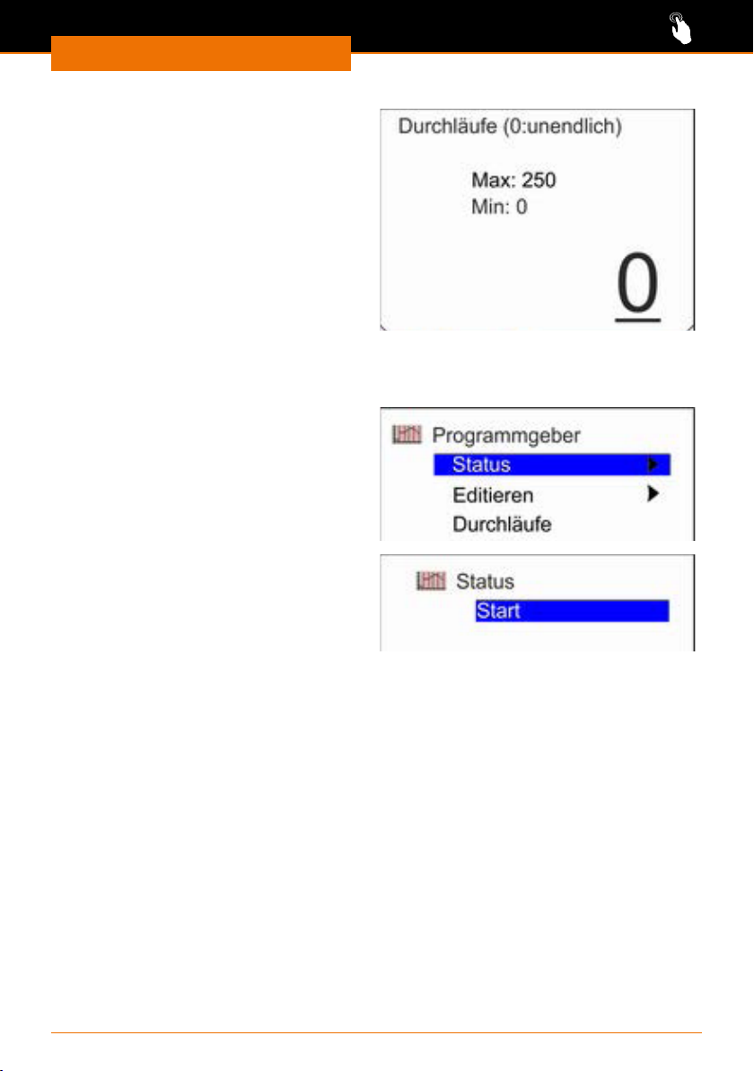
Bedienung
✓ Mit dem Wert „0” wird das Programm
unendlich wiederholt.
➜ Drücken Sie die Peiltaste links,
um eine 2- oder 3-stellige Anzahl
einzugeben.
➜ Geben Sie mit Hilfe der Pfeiltasten
auf /ab die gewünschte Anzahl der
Durchläufe an und bestätigen Sie Ihre
Änderung mit der Taste „Select”.
Programm starten und beenden
✓ Das Gerät ist eingeschaltet.
➜ Wählen Sie das Untermenü
„Programmgeber” / „Status”.
✓ Ist kein Programm aktiv, erhalten
Sie ausschließlich die Option „Start”
angezeigt.
✓ Ist ein Programm aktiviert, erhalten
Sie die Optionen „Pause” und „Stop”
angezeigt.
✓ Wurde ein Programm mit „Pause
angehalten, erhalten Sie die Optionen
„Weiter” und „Stop” angezeigt.
➜ Bestätigen Sie die jeweils gewünschte
Option mit der Taste „Select”.
91
Page 92
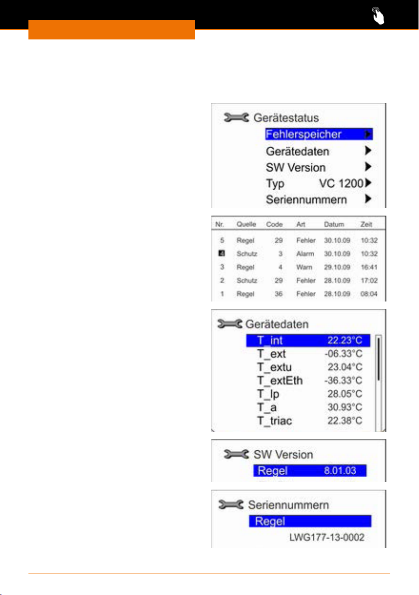
Bedienung
Gerätestatus
Im Menü „Gerätestatus” können Sie verschiedene im Gerät hinterlegte Daten abrufen.
Bei Menüpunkt „Typ ...” bekommen Sie direkt Ihre Gerätevariante angezeigt.
✓ Das Gerät ist eingeschaltet.
➜ Wählen Sie das Untermenü
„Einstellungen” / „Gerätestatus”.
➜ Wählen Sie mit Hilfe der Pfeiltasten
eine der angebotenen Optionen aus
und bestätigen Sie Ihre Auswahl mit
der Taste „Select”.
➜ Kehren Sie mit der Pfeiltaste links
zurück zum Menü „Gerätestatus”.
Fehlerspeicher
(Zur Interpretation des Fehlerspeichers
siehe Kapitel: „Fehlerbehandlung,
Störungen und deren Beseitigung”.)
Gerätedaten
Hier werden die Ist- und Solltemperaturen
an den verschiedenen Temperaturfühlern
angezeigt.
SW Version
Hinter „Regel” wird die aktuelle Software
Version angezeigt.
Seriennummer
Hinter „Regel” wird die Seriennummer für
das Gerät angezeigt.
92
Page 93
Bedienung
Schnittstellen
Warnung:
Stromschlaggefahr!
Wenn die Schnittstelleneingänge und -ausgänge mit zu hohen Spannungen
belegt werden und nicht ausreichend isoliert sind, können im Fehlerfall
metallische Teile, wie z.B. das Gehäuse unter Spannung geraten.
Trennen Sie Kleinspannungseingänge und -ausgänge über 25 V AC
bzw. 60 V DC sicher gemäß DIN EN 61140, bzw. durch doppelte oder
verstärkte Isolierung gemäß DIN EN 60730-1 oder DIN 60950-1.
Verwenden Sie ausschließlich geschirmte Anschlussleitungen. Verbinden
Sie die Abschir mung mit dem Steckergehäuse.
Vorsicht:
Mögliche Beschädigung des Geräts
Wenn die Anschlüsse am Gerät nicht abgedeckt sind, kann
Flüssigkeit an stromführende Teile gelangen. Eindringende
Flüssigkeiten können zu Fehlfunktionen der Schnittstellen führen und
es kann zu Kurzschluss kommen.
Die Schnittstellenanschlüsse an der Geräterückseite müssen immer
abgedeckt sein.
In welchen Störungssituationen ein Signal über die Schnittstelle ausge-
geben wird, kann über das Display eingestellt werden.
93
Page 94
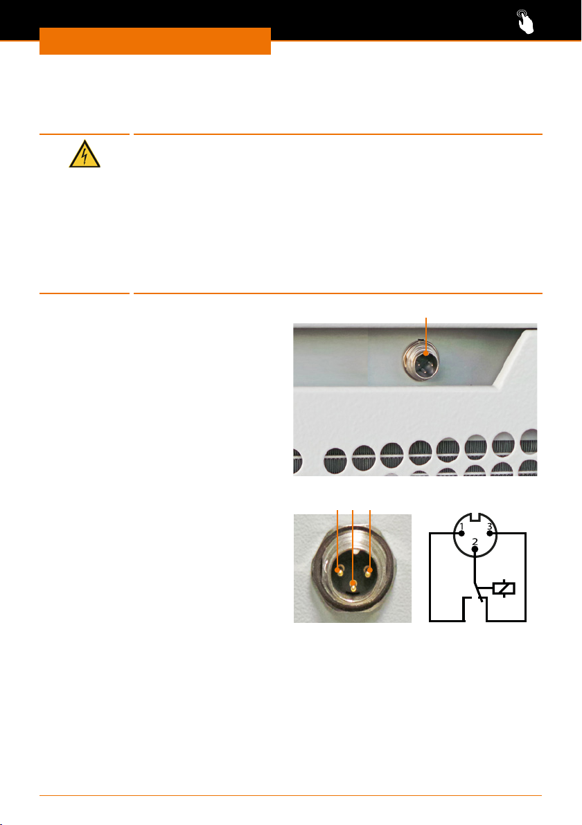
Bedienung
Alarmausgang anschließen
Mit Hilfe des Alarmausgangs können Sie über einen potentialfreier Kontakt Störungen an
ein extern angschlossenes Geräte weitergeben.
Warnung:
Stromschlaggefahr!
Wenn die Schnittstellenein- und -ausgänge mit zu hohen Spannungen
belegt werden und nicht ausreichend isoliert sind, können im Fehlerfall
metallische Teile, wie z.B. das Gehäuse unter Spannung geraten.
Trennen Sie Kleinspannungseingänge und -ausgänge über 25 V AC
bzw. 60 V DC sicher gemäß DIN EN 61140, bzw. durch doppelte oder
verstärkte Isolierung gemäß DIN EN 60730-1 oder DIN 60950-1.
Verwenden Sie ausschließlich geschirmte Anschlussleitungen.
Verbinden Sie die Abschir mung mit dem Steckergehäuse. Decken Sie
unbenutzte Steckverbindungen mit Schutzkappen ab.
Alarmausgang
Der Alarmausgang benden sich auf der
Gerätevorderseite in der Grimulde des
Lüftungsgitters.
Alarmausgang kongurieren
Werkseitig ist das Gerät so konguriert, dass eine sicherheitsrelevante
Störung immer am Alarmausgang ausge-
geben wird. Zusätzlich können Sie den
Alarmausgang so kongurieren, dass auch
im Stand-by-Betrieb ein Alarm ausgegeben wird.
An den Alarmausgang darf maximal
30 V DC bei 0,2 A angeschlossen werden.
Ruhezustand
Bei ausgeschaltetem Gerät oder wenn
nach dem Einschalten eine Störung
vorliegt bendet sich der Alarmausgang
im Ruhezustand:
▪ Pin 1 und 2 sind geönet.
▪ Pin 3 und 2 sind geschlossen.
Gutzustand
Bei eingeschaltetem Gerät und störungsfreien Betrieb bendet sich der Alarmausgang im
Gutzustand:
▪ Pin 1 und 2 sind geschlossen.
▪ Pin 3 und 2 sind geönet.
Alarmausgang
2 3
1
Alarmausgang
Alarmausgang
im Ruhezustand
94
Page 95
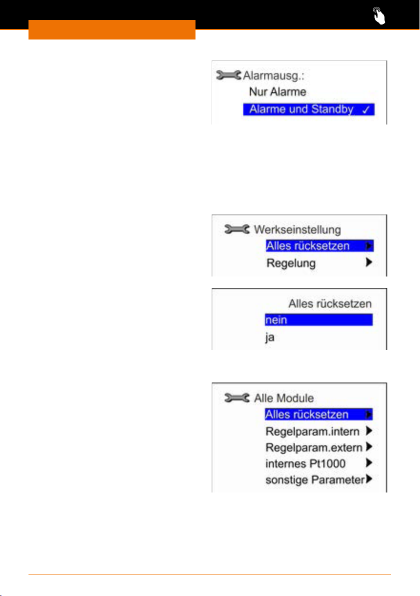
Bedienung
✓ Das Gerät ist eingeschaltet.
➜ Wählen Sie das Untermenü
„Einstellungen” / „Grundeinstellungen”
/ „Alarmausg.”.
➜ Wählen Sie mit Hilfe der Pfeiltasten
eine der angebotenen Optionen aus
und bestätigen Sie Ihre Auswahl mit
der Taste „Select”.
Werkseinstellung wiederherstellen
Alle Einstellungen, die Sie n einem der Untermenüs geändert haben, können Sie unter
dem Menüpunkt „Werkseinstellung” wieder auf die ursprüngliche Werkseinstellung
zurücksetzen.
✓ Das Gerät ist eingeschaltet.
➜ Wählen Sie das Untermenü
„Einstellungen” / „Werkseinstellung”.
➜ Wählen Sie mit Hilfe der Pfeiltasten
eine der angebotenen Optionen aus
und bestätigen Sie Ihre Auswahl mit
der Taste „Select”.
Alle Einstellungen zurücksetzen
✓ Das Gerät ist eingeschaltet.
➜ Wählen Sie das Untermenü
„Einstellungen” / „Werkseinstellung” /
„Alles zurücksetzen”.
➜ Wählen Sie mit Hilfe der Pfeiltasten
eine der angebotenen Optionen aus
und bestätigen Sie Ihre Auswahl mit
der Taste „Select”.
Einstellungen einzeln zurücksetzen
✓ Das Gerät ist eingeschaltet.
➜ Wählen Sie das Untermenü
„Einstellungen” / „Werkseinstellung” /
„Regelung”.
➜ Wählen Sie mit Hilfe der Pfeiltasten
eine der angebotenen Optionen aus
und bestätigen Sie Ihre Auswahl mit
der Taste „Select”.
✓ Bei jeder usgeählten Einstellung
erhalten Sie noch einmal die
Möglichkeit, mit „ja” oder „nein” zu
bestätigen.
✓ Unter „sonstige Parameter” können Sie den Sollwert sowie die Stromaufnahme
zurücksetzen.
95
Page 96
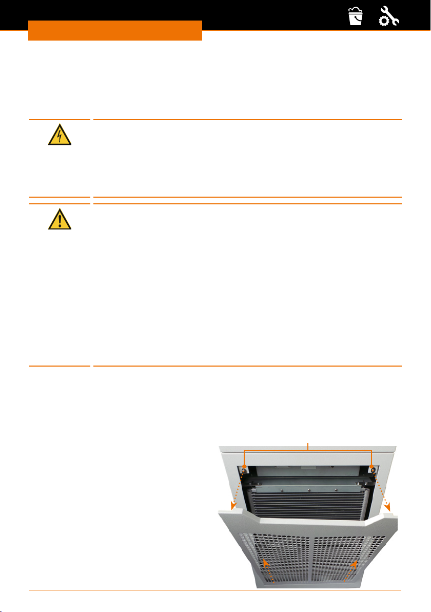
Reinigung & Wartung
Reinigung
Reinigung und Wartung
Gerät reinigen
Zur Reinigung können Sie das Gehäuse und die Oberäche des Gerätes mit einem
feuchten Tuch und gegebenenfalls mit milder Seifenlauge abwischen.
Warnung!
Stromschlaggefahr!
Eindringende Flüssigkeiten können dazu führen, dass das Gerät unter
Spannung gerät, wenn es noch an die Stromversorgung angeschlossen ist.
Bevor Sie das Gerät reinigen:
▪ Schalten Sie das Gerät aus.
▪ Ziehen Sie den Netzstecker.
Vorsicht:
Gerätebeschädigung
Eindringende Flüssigkeiten können die Elektronik des Gerätes
beschädigen.
Wischen Sie die Oberäche immer nur feucht und niemals nass ab.
Vorsicht:
Oberächenbeschädigung
Die Oberächen können durch unsachgemäße Reinigung beschädigt
werden.
Verwenden Sie zur Reinigung auf keinen Fall:
▪ Chlorbleiche oder auf Chlorbasis aufbauende Putzmittel
▪ lösmittelhaltige Substanzen (z.B. Aceton)
▪ Ammoniak
▪ abbrasive Reinigungsmittel wie Putzwolle, Scheuermittel oder
Reinigungsmittel mit metallischen Bestandteilen
Luftlter reinigen
Das Lüftungsgitter vor dem Luftlter wird zusätzlich zur mechanischen Halterung durch
zwei Magnete gehalten.
✓ Das Gerät ist ausgeschaltet und vom Stromnetz getrennt.
➜ Fassen Sie mit beiden Händen oben in die Grimulde des Lüftungsgitters.
➜ Ziehen Sie das Lüftungsgitter von den
oberen Magneten ab.
➜ Ziehen Sie das Lüftungsgitter leicht nach
oben und ziehen Sie es unten von den
Haltenasen des Gerätes ab.
➜ Kehren oder saugen Sie den Luftlter
und gegebenenfalls das Lüftungsgitter ab.
➜ Schieben Sie das Lüftungsgitter unten
mit den Schlitzen über die beiden
Haltenasen.
➜ Fassen Sie in die Grimulde und drücken
Sie das Lüftungsgitter oben wieder
vorsichtig an das Gerät.
96
Magnete
Page 97
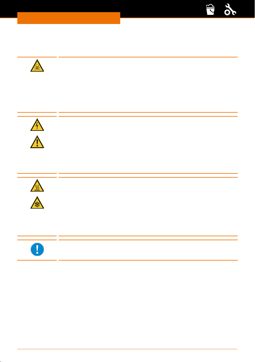
Reinigung & Wartung
Wartung
Instandhaltung
Gefahr!
Vergiftungsgefahr! Gefahr für die Umwelt!
Durch unsachgemäße Reparaturen am internen Kältekreislauf kann es
zu Undichtigkeiten kommen und das Kältemittel kann unkontrolliert
entweichen. Dadurch können Mitarbeiter sich vergiften und es können
erhebliche Umweltschäden entstehen.
Reparatur- und Wartungsarbeiten am internen Kältekreislauf dürfen
nur von einer durch Heidolph Instruments autorisierten Fachkraft
durchgeführt werden.
Warnung!
Stromschlaggefahr! Verletzungsgefahr!
Bei Reparaturen können Sie in Kontakt mit spannungsführenden oder
bewegten Teilen kommen. Dies kann zu Stromschlag, Stoß, Schneiden
oder Quetschen
Vor jeglichen Instandhaltungsarbeiten muss das Gerät vom Netz
getrennt werden.
Reparaturen dürfen nur von einer durch Heidolph Instruments
autorisierten Fachkraft durchgeführt werden.
Warnung!
Verbrennungsgefahr! Erfrierungsgefahr
Durch Berührung von heißen oder kalten Geräteteilen, Zubehör und
Temperierüssigkeit können Sie sich sowohl Verbrennungen als auch
Erfrierungen zuziehen.
Tragen Sie bei Wartungsarbeiten immer Schutzhandschuhe und
Schutzkleidung,
Bringen Sie Geräteteile, Zubehör und Temperierüssigkeit vor
Berühren auf Raumtemperatur.
Wenn das Gerät mit gefährlichen Materialien in Kontakt kam, muss
vor allen Instandsetzungsarbeiten eine Dekontaminierung des Geräts
durchgeführt werden.
97
Page 98
Reinigung & Wartung
Wartungsintervalle
Die in der folgenden Tabelle beschriebenen Wartungsintervalle müssen eingehalten werden. Vor jedem längeren unbeaufsichtigtem Betrieb sind die folgenden
Wartungsarbeiten verpichtend.
Intervall Wartungsarbeit
monatlich ▪ Prüfung der Entleerungsschraube durch Besichtigung von außen
halbjährlich Prüfung der Temperierüssigkeit
Eine eventuell notwendige Reparatur darf nur durch einen von Heidolph Instruments
autorisierten Fachmann ausgeführt werden.
Wenden Sie sich hierzu an Ihren Heidolph Instruments Händler oder eine Vertretung von
Heidolph Instruments.
Temperierüssigkeit prüfen
Verunreinigte oder degenerierte Temperierüssigkeit muss erneuert werden. Eine Weiterverwendung der Temperierüssigkeit ist nur bei entsprechenden Prüfungs ergebnissen
zulässig. Die Prüfung der Temperierüssigkeit muss nach DIN 51529 erfolgen.
▪ Prüfung der externen Schläuche auf Materialermüdung
▪ Reinigung des Luftlters
98
Page 99
Fehlerbehandlung
Störungen und deren Beseitigung
Alarme sind sicherheitsrelevant. Das Gerät wird in Stand-by-Modus geschaltet.
✓ Es ertönt rhytmisch ein akkustisches Signal.
➜ Nach Behebung der Ursache drücken Sie die Taste „Select”, um die Alarme
zurückzusetzen.
✓ Der Alarm ist aufgehoben.
Alarm code Ursache Behebung
02 Unterniveau erkannt ▪ Alle Anschlüsse auf Dichtigkeit prüfen
Warnungen sind nicht sicherheitsrelevant. Das Gerät läuft weiter.
✓ Es ertönt ein länger anhaltendes akkustisches Signal, das periodisch wiederholt wird.
➜ Nach Behebung der Ursache drücken Sie die Taste „Select”, um die Warnungen
zurückzusetzen.
✓ Die Warnung ist aufgehoben.
1. Warnungen Regel system
Code Fehler Behebung
001 Überlauf beim CAN-Empfang Lokalen Händler vor Ort kontaktieren
002 Watchdog-Reset Lokalen Händler vor Ort kontaktieren
003 T il-Begrenzung aktiv Lokalen Händler vor Ort kontaktieren
004 T ih-Begrenzung aktiv Lokalen Händler vor Ort kontaktieren
005 unzulässige interne Parameter Lokalen Händler vor Ort kontaktieren
006 unzulässige Programmdaten Überprüfen und korrigieren Sie
007 unzulässige Parameter im Speicher Lokalen Händler vor Ort kontaktieren
008 Problem beim internen Datenaustausch Lokalen Händler vor Ort kontaktieren
009 Unbekanntes Modul angeschlossen Lokalen Händler vor Ort kontaktieren
010 Softwareversion vom Regelsystem zu
alt
011 Softwareversion vom Sicherheitssystem
zu alt
012 Softwareversion der Fernbedieneinheit
Command zu alt
013 Softwareversion vom Kältemodul zu alt Lokalen Händler vor Ort kontaktieren
014 Softwareversion vom Analogmodul zu
alt
017 Softwareversion vom Magnetventil 0
zu alt
Fehlerbehandlung
▪ Temperierüssigkeit auüllen
▪ Taste „Select” drücken
die Parameter Ihres aufgerufenen
aktiven Programms
Lokalen Händler vor Ort kontaktieren
Lokalen Händler vor Ort kontaktieren
Lokalen Händler vor Ort kontaktieren
Lokalen Händler vor Ort kontaktieren
Lokalen Händler vor Ort kontaktieren
99
Page 100

Fehlerbehandlung
Code Fehler Behebung
018 Softwareversion vom Magnetventil 1
zu alt
019 Softwareversion vom Magnetventil 2
zu alt
020 Softwareversion vom Magnetventil 3
zu alt
021 Softwareversion vom Magnetventil 4
zu alt
022 Softwareversion von Pumpe 0 zu alt Lokalen Händler vor Ort kontaktieren
023 Softwareversion von Pumpe 1 zu alt Lokalen Händler vor Ort kontaktieren
024 Softwareversion von Pumpe 2 zu alt Lokalen Händler vor Ort kontaktieren
025 Softwareversion von Pumpe 3 zu alt Lokalen Händler vor Ort kontaktieren
026 Softwareversion vom
Hochtemperaturkühler 3 zu alt
028 Softwareversion von Ethernet zu alt Lokalen Händler vor Ort kontaktieren
029 Softwareversion von EtherCAT zu alt Lokalen Händler vor Ort kontaktieren
033 Interne Uhr defekt oder keine
Batterieversorgung der Uhr
034 Sollwert wurde bei laufendem
Programmgeber verändert
041 falsche Netzspannungseinstellung Lokalen Händler vor Ort kontaktieren
042 Gerätetyp nicht konguriert Lokalen Händler vor Ort kontaktieren
043 Netzspannung nicht konguriert Lokalen Händler vor Ort kontaktieren
050 Unterniveau Temperierüssikgeit Temperierüssigkeit nachfüllen
051 Überniveau Temperierüssikgeit Temperierüssikgeit ablassen
055 Puerüberlauf beim CAN-Empfang Lokalen Händler vor Ort kontaktieren
Lokalen Händler vor Ort kontaktieren
Lokalen Händler vor Ort kontaktieren
Lokalen Händler vor Ort kontaktieren
Lokalen Händler vor Ort kontaktieren
Lokalen Händler vor Ort kontaktieren
Lokalen Händler vor Ort kontaktieren
Lokalen Händler vor Ort kontaktieren
2. Warnungen Sicherheit system
Code Fehler Behebung
101 Überlauf beim CAN-Empfang Lokalen Händler vor Ort kontaktieren
102 Watchdog-Reset Lokalen Händler vor Ort kontaktieren
103 Heizkörper haben unterschidliche
Leistungen
104 Heizkörper 1 defekt Lokalen Händler vor Ort kontaktieren
105 Heizkörper 2 defekt Lokalen Händler vor Ort kontaktieren
106 Heizkörper 3 defekt Lokalen Händler vor Ort kontaktieren
107 unzulässige Parameter im Speicher Lokalen Händler vor Ort kontaktieren
108 Problem beim internen Datenaustausch Lokalen Händler vor Ort kontaktieren
100
Lokalen Händler vor Ort kontaktieren
 Loading...