

HEIDELBERG Suprasetter 145, Suprasetter 162, Suprasetter 190 User Manual

Suprasetter 145/162/190
User’s Guide
02/2019
Order No. PG.999.0005

ABC
Imprint/Company Address
Copyright © 2019 Heidelberger
Druckmaschinen AG.
No part of this book may be reproduced without prior written permission.
Heidelberger Druckmaschinen AG
Dr.-Hell-Straße
24107 Kiel
Germany
Phone +49 431 386-0
Fax +49 431 386-1380
www.heidelberg.com
. . . . . . . . . . . . . . . . . . . . . . . . . . . . . . . . . . . . . . . . . . . . . . . . . . . . . . . . . . . . . . .
Heidelberg and the Heidelberg logo
are registered trademarks of Heidelberger Druckmaschinen AG.
Suprasetter is a trademark of Heidelberger Druckmaschinen AG.
Other company names, product
names and trademarks not expressly
mentioned in this manual are trademarks or registered trademarks of
the corresponding manufacturers
and fall within the regulations
regarding the protection of trademarks.
. . . . . . . . . . . . . . . . . . . . . . . . . . . . . . . . . . . . . . . . . . . . . . . . . . . . . . . . . . . . . . .
Important notice:
We are dedicated to improving and
enhancing our products. Consequently, the information in this
manual is subject to change without
notice.
Heidelberger Druckmaschinen AG
assumes no responsibility for information and description as far as
third-party products are concerned.
The information contained in this
manual about performance and
speed as well as technical data concerning application of our products
is not legally binding as it does not
constitute a written contract of features.
If any problems occur with the product described in this manual, please
contact the agency which is responsible for you.
Translation of Original operating
manual
Order No. PG.999.0005
02/2019
Printed in Germany.
. . . . . . . . . . . . . . . . . . . . . . . . . . . . . . . . . . . . . . . . . . . . . . . . . . . . . . . . . . . . . . .

Table of Contents
Table of Co nte nts
Table of Contents
3
Before you start ...
Safety Notes . . . . . . . . . . . . . . . . . . . . . . . . . . . . . . . . . . . . . . . . . 9
Device Names . . . . . . . . . . . . . . . . . . . . . . . . . . . . . . . . . . . . . . 9
Correct Use . . . . . . . . . . . . . . . . . . . . . . . . . . . . . . . . . . . . . . . . 9
Avoid Misuse . . . . . . . . . . . . . . . . . . . . . . . . . . . . . . . . . . . . . . . 9
Qualification of the Users . . . . . . . . . . . . . . . . . . . . . . . . . . . . . . 10
General . . . . . . . . . . . . . . . . . . . . . . . . . . . . . . . . . . . . . . . . . . . 10
Power Switch with Emergency Cutoff Function . . . . . . . . . . . . . . 11
Emergency Stop Switch . . . . . . . . . . . . . . . . . . . . . . . . . . . . . . . 12
On/Off button . . . . . . . . . . . . . . . . . . . . . . . . . . . . . . . . . . . . . . . 12
Laser Safety . . . . . . . . . . . . . . . . . . . . . . . . . . . . . . . . . . . . . . . . 12
Service and Maintenance . . . . . . . . . . . . . . . . . . . . . . . . . . . . . . 13
Safety Loop . . . . . . . . . . . . . . . . . . . . . . . . . . . . . . . . . . . . . . . . 14
Check of the safety loop . . . . . . . . . . . . . . . . . . . . . . . . . . . . . . . 14
Automatic check of the safety loop . . . . . . . . . . . . . . . . . . . . . . 14
Manual check of the safety loop . . . . . . . . . . . . . . . . . . . . . . . . 15
ESD Protective Measures for Prepress Systems and Operators . . . 16
Basics . . . . . . . . . . . . . . . . . . . . . . . . . . . . . . . . . . . . . . . . . . . 16
Formation . . . . . . . . . . . . . . . . . . . . . . . . . . . . . . . . . . . . . . . . 16
Practical Tips . . . . . . . . . . . . . . . . . . . . . . . . . . . . . . . . . . . . . 17
Standards/Sources . . . . . . . . . . . . . . . . . . . . . . . . . . . . . . . . . 18
Disposal of the Suprasetter 145/162/190 . . . . . . . . . . . . . . . . . . . . 18
Converting the Suprasetter 145/162/190 . . . . . . . . . . . . . . . . . . . . . 18
About This Documentation . . . . . . . . . . . . . . . . . . . . . . . . . . . . . . . 19
What You Should Already Know . . . . . . . . . . . . . . . . . . . . . . . . . 19
Further Documentation . . . . . . . . . . . . . . . . . . . . . . . . . . . . . . . . 19
Symbols and Styles . . . . . . . . . . . . . . . . . . . . . . . . . . . . . . . . . 20
Suprasetter 145/162/190 – User’s Guide 3

Table of Contents
Important Information . . . . . . . . . . . . . . . . . . . . . . . . . . . . . . . . 21
Heidelberg online . . . . . . . . . . . . . . . . . . . . . . . . . . . . . . . . . . . . . 21
Introduction
Description of the Unit and its Functions . . . . . . . . . . . . . . . . . . . . 23
Status LEDs . . . . . . . . . . . . . . . . . . . . . . . . . . . . . . . . . . . . . . . . 24
Power switch . . . . . . . . . . . . . . . . . . . . . . . . . . . . . . . . . . . . . . . 26
On/Off button . . . . . . . . . . . . . . . . . . . . . . . . . . . . . . . . . . . . . . 27
Keeping Access Routes Clear . . . . . . . . . . . . . . . . . . . . . . . . . . . 27
Notes on the Use of Plates . . . . . . . . . . . . . . . . . . . . . . . . . . . . . 28
Notes on Installation
Notes on Installation . . . . . . . . . . . . . . . . . . . . . . . . . . . . . . . . . . . 29
Transport of the Suprasetter 145/162/190 . . . . . . . . . . . . . . . . . . 29
Installing the Device . . . . . . . . . . . . . . . . . . . . . . . . . . . . . . . . . . 29
Automatic Cutouts . . . . . . . . . . . . . . . . . . . . . . . . . . . . . . . . . . . 29
Software Installation (Container Version) . . . . . . . . . . . . . . . . . . 30
Saving a Backup of the Recorder Configuration . . . . . . . . . . . . . . 31
Selecting the User Interface Language . . . . . . . . . . . . . . . . . . . . 31
Operation
Power-on and Power-off Rules for Recorders with a Linux
Operating System . . . . . . . . . . . . . . . . . . . . . . . . . . . . . . . . . . . . . 33
Power-on order . . . . . . . . . . . . . . . . . . . . . . . . . . . . . . . . . . . . . 33
Shutdown order . . . . . . . . . . . . . . . . . . . . . . . . . . . . . . . . . . . . . 33
Switching on the Device . . . . . . . . . . . . . . . . . . . . . . . . . . . . . . . . 34
Manual Startup . . . . . . . . . . . . . . . . . . . . . . . . . . . . . . . . . . . . . 34
Automatic Startup . . . . . . . . . . . . . . . . . . . . . . . . . . . . . . . . . . . 35
Switching Off the Device . . . . . . . . . . . . . . . . . . . . . . . . . . . . . . . . 36
4Version 2019

Table of Contents
Shutdown using the User Interface on the Workstation . . . . . . . 37
Shutdown with the On/Off Button on the Device . . . . . . . . . . . . 37
Quick Shutdown with the On/Off button on the Suprasetter. . . . 38
Material Handling . . . . . . . . . . . . . . . . . . . . . . . . . . . . . . . . . . . . 40
Material storage . . . . . . . . . . . . . . . . . . . . . . . . . . . . . . . . . . . . 40
Loading Plates on the Manual Device and on the Semi-automatic
Device . . . . . . . . . . . . . . . . . . . . . . . . . . . . . . . . . . . . . . . . . . . . . 40
Operation . . . . . . . . . . . . . . . . . . . . . . . . . . . . . . . . . . . . . . . . . 42
Unloading the Plates on a Manual Device . . . . . . . . . . . . . . . . . . . 45
Operation . . . . . . . . . . . . . . . . . . . . . . . . . . . . . . . . . . . . . . . . . 45
Loading Plates on a Fully Automated Device . . . . . . . . . . . . . . . . . 46
Operation . . . . . . . . . . . . . . . . . . . . . . . . . . . . . . . . . . . . . . . . . 46
Empty waste box . . . . . . . . . . . . . . . . . . . . . . . . . . . . . . . . . . . . . 49
Operation . . . . . . . . . . . . . . . . . . . . . . . . . . . . . . . . . . . . . . . . . 49
Troubleshooting . . . . . . . . . . . . . . . . . . . . . . . . . . . . . . . . . . . . . . 53
Operation . . . . . . . . . . . . . . . . . . . . . . . . . . . . . . . . . . . . . . . . . 53
Fixing Jamming . . . . . . . . . . . . . . . . . . . . . . . . . . . . . . . . . . . . 54
Switching on an Automatic Cutout . . . . . . . . . . . . . . . . . . . . . . 56
Service and Maintenance
General . . . . . . . . . . . . . . . . . . . . . . . . . . . . . . . . . . . . . . . . . . . . 59
Safety Notes . . . . . . . . . . . . . . . . . . . . . . . . . . . . . . . . . . . . . . . 59
Qualification of the Users . . . . . . . . . . . . . . . . . . . . . . . . . . . . . 60
Maintenance by the User . . . . . . . . . . . . . . . . . . . . . . . . . . . . . 60
Cleaning the Unit . . . . . . . . . . . . . . . . . . . . . . . . . . . . . . . . . . . 60
Cleaning the Cleaning Roller on a Manual Device and on a
Semi-automatic Device . . . . . . . . . . . . . . . . . . . . . . . . . . . . . . . . 61
Suprasetter 145/162/190 – User’s Guide 5

Table of Contents
Cleaning the Cleaning Roller on a Fully Automated Device with a
Cross Conveyor or OLP Table . . . . . . . . . . . . . . . . . . . . . . . . . . . 63
Removing Punch Waste on a Manual Device and on a
Semi-automatic Device . . . . . . . . . . . . . . . . . . . . . . . . . . . . . . . 65
Removing Punch Waste on a Fully Automated Device with a
Cross Conveyor or OLP Table . . . . . . . . . . . . . . . . . . . . . . . . . . . 68
Changing the Filter Kit in the Suction Device . . . . . . . . . . . . . . . 71
Technical Data
Overview . . . . . . . . . . . . . . . . . . . . . . . . . . . . . . . . . . . . . . . . . . . 77
Protection and Safety Requirements . . . . . . . . . . . . . . . . . . . . . . . 78
Standards . . . . . . . . . . . . . . . . . . . . . . . . . . . . . . . . . . . . . . . . . 78
General . . . . . . . . . . . . . . . . . . . . . . . . . . . . . . . . . . . . . . . . . 79
Mechanical Safety . . . . . . . . . . . . . . . . . . . . . . . . . . . . . . . . . 79
Electrical safety . . . . . . . . . . . . . . . . . . . . . . . . . . . . . . . . . . . . . 80
Electromagnetic compatibility (EMC) . . . . . . . . . . . . . . . . . . . . . 80
Interference Emission (Stray Radiation and Interference Voltage) 80
Interference immunity . . . . . . . . . . . . . . . . . . . . . . . . . . . . . . . . 81
Radio Interference Suppression . . . . . . . . . . . . . . . . . . . . . . . . . 81
Approvals and Conformity . . . . . . . . . . . . . . . . . . . . . . . . . . . . . 81
CE-Declaration of Conformity . . . . . . . . . . . . . . . . . . . . . . . . . . . . 82
Labels on the Suprasetter 145/162/190 . . . . . . . . . . . . . . . . . . . 83
Disposal
Disposal . . . . . . . . . . . . . . . . . . . . . . . . . . . . . . . . . . . . . . . . . . . 105
Disposal of the device . . . . . . . . . . . . . . . . . . . . . . . . . . . . . . . . . 105
Disposal of the Recorder . . . . . . . . . . . . . . . . . . . . . . . . . . . . . 106
Harmful Substances . . . . . . . . . . . . . . . . . . . . . . . . . . . . . . . 106
Recyclable Materials . . . . . . . . . . . . . . . . . . . . . . . . . . . . . . . 108
Dismantling . . . . . . . . . . . . . . . . . . . . . . . . . . . . . . . . . . . . . 109
6Version 2019

Table of Contents
Disposal of the Loader/Unloader . . . . . . . . . . . . . . . . . . . . . . . . 120
Harmful Substances . . . . . . . . . . . . . . . . . . . . . . . . . . . . . . . 120
Recyclable Materials . . . . . . . . . . . . . . . . . . . . . . . . . . . . . . . 121
Dismantling . . . . . . . . . . . . . . . . . . . . . . . . . . . . . . . . . . . . . . 123
Disposal of the Separator . . . . . . . . . . . . . . . . . . . . . . . . . . . . . 126
Harmful Substances . . . . . . . . . . . . . . . . . . . . . . . . . . . . . . . 126
Recyclable Materials . . . . . . . . . . . . . . . . . . . . . . . . . . . . . . . 127
Dismantling . . . . . . . . . . . . . . . . . . . . . . . . . . . . . . . . . . . . . . 128
Disposal of the Tray Loader . . . . . . . . . . . . . . . . . . . . . . . . . . . 130
Harmful Substances . . . . . . . . . . . . . . . . . . . . . . . . . . . . . . . 130
Recyclable Materials . . . . . . . . . . . . . . . . . . . . . . . . . . . . . . . 131
Dismantling . . . . . . . . . . . . . . . . . . . . . . . . . . . . . . . . . . . . . . 132
Disposal of the Magazine . . . . . . . . . . . . . . . . . . . . . . . . . . . . . 134
Recyclable Materials . . . . . . . . . . . . . . . . . . . . . . . . . . . . . . . 134
Dismantling . . . . . . . . . . . . . . . . . . . . . . . . . . . . . . . . . . . . . . 135
Suprasetter 145/162/190 – User’s Guide 7


Before you start ...
Before you start ...
Safety Notes
The Suprasetter complies with the safety regulations of the standards and
specifications listed in the "Technical Data" chapter.
Device Names
Sales designation Type designation
Suprasetter 145/162/190 PG.010.000B
Separator PG.050.000B
Tray loader PG.090.000B
Cassette magazine PG.030.000B
I/O table PG.021.000B
Correct Use
The Suprasetter is a laser imagesetter for imaging offset printing plates and
may only be used for this purpose as described in the customer documentation.
All other use that does not comply with the correct use is prohibited.
Avoid Misuse
Do not place any objects or liquids on the Suprasetter.
Ventilation outlets must be kept clear at all times.
Do not use the Suprasetter as a seat.
Suprasetter 145/162/190 – User’s Guide 9

Before you start ...
Qualification of the Users
After installation, users will be instructed in the operation and service and
maintenance of the Suprasetter by Heidelberg service personnel. Further
instruction, for example, for new staff employed subsequently, must be
ensured by the operator of the Suprasetter.
General
The Suprasetter may be installed only by authorized service personnel. The
ambient conditions must be observed.
For the operating company of a print shop, it is important that the exposure
limits regarding the breathable air in the work area, where the Suprasetter is
located, are adhered to. The air exchange must be arranged in such a way that
the measured dust particles are regularly below the exposure limit values. In
accordance with the state of the art, this can be achieved with an 8 to 10 air
change rate per hour. If this is not the case at the installation site, the operating company should install an additional exhaust system.
Warning: Unauthorized opening of any parts of the casing not specifically referred to in the operating manual and inexpert repairs can lead
to considerable danger for the user.
Servicing
this purpose. The relevant accident prevention regulations must be
observed at all times.
Non-observance of accident prevention regulations can lead to the loss
of accident insurance cover.
Warning: Plate edges can be sharp. You can injure your hands if you do
not wear protective gloves.
10 Version 2019
may only be performed by authorized personnel trained for
Before you start ...
Warning: The following loads should not be exceeded: women 15 kg,
men 25 kg.
Warning: The key-operated switch that can be seen after the top right
side panel is opened may be operated only by service personnel and not
by the operator.
The key-operated switch bypasses the safety loop.
The following risks can occur:
- Hazard of being crushed by moving parts.
- Injury from electric shock.
Warning: If cleaning the Suprasetter involves the use of liquids, discon-
nect it from the power supply beforehand. Do this by pulling out the
power connector on the service tap or by switching it off with the power
switch.
Warning: You run the risk of injuring your fingers on the sharp edges of
the printing plates if your fingers are between the insertion/ejection
table and the cross conveyor of the Suprasetter. The protective cover is
used to avoid this.
Warning: Wear disposable gloves and light dust mask We recom-
mend that you wear the disposable gloves and light dust mask included
in the kit when you are changing the filters. After you remove the filters,
clean the casing with a vacuum cleaner. Place the used filters, dispos-
able gloves, dust mask and vacuum cleaner bag in a plastic bag, tie the
bag up and dispose of it as general commercial waste. If you are not
sure about disposal procedures, contact your local waste disposal com-
pany for details.
Power Switch with Emergency Cutoff Function
The Suprasetter is fully cut off from the power supply by the power switch (red
rotary switch).
Suprasetter 145/162/190 – User’s Guide 11

Before you start ...
The power switch (red rotary switch) separates the Suprasetter's four poles
from the power supply. In an emergency, this power switch is used as an emergency stop switch for the Suprasetter.
Emergency Stop Switch
All mechanical motions in the device are stopped and the invisible laser beam
is switched off when the emergency stop switches (fully automated device: 8
units, semi-automated device: 4 units) are used.
Use these switches in cases of emergency only. They are located behind the
panels of the device. They are designed for an emergency during servicing.
On/Off button
The Suprasetter is only de-energized by the On/Off button.
The CEE or Nema outlets of the service line must be easily accessible at all
times.
To fully separate the Suprasetter from mains, e.g. in case of danger, the device
must be de-energized by actuating the power switch or unplugging the CEE or
Nema plug if applicable.
When connecting or disconnecting the power cable, make sure that your
hands are not wet and only hold the cable at the connector, if the cable has
one. A damaged power cable can cause leakage currents and electric shocks.
Protect the power cable from being damaged. Never place any heavy objects
upon it and do not allow it to get jammed.
Laser Safety
The laser imagesetter is a Class 1 laser product.
This means that the invisible
shielded by means of protective covers.
12 Version 2019
laser radiation produced in the Suprasetter is

Before you start ...
If used as directed, the user is never exposed to danger from the laser beam.
The laser systems used in the Suprasetter are Class 4 products (> 500 mW).
Companies servicing the equipment in Germany must appoint a laser protection officer in compliance with the Accident Prevention Regulations (BGV B2) of
the Professional Trade Association.
Servicing may only be carried out by Heidelberg personnel who have
been trained by appropriate laser protection officers for this purpose.
Service and Maintenance
Servicing may be done solely by persons who are authorized by Heidelberg to
do so.
The relevant accident prevention regulations must be observed at all times.
Warning: Never remove covers or any other parts of the casing except
for the work described in the "Service and Maintenance" and "Trouble-
shooting" chapters. Keep exactly to the procedures laid down when
doing this.
If you do not, the invisible
skin and/or you may suffer a fatal electric shock.
Warning: You may be exposed to dangerous radiation by the invisible
laser beams if you use operating or adjustment equipment other than
those mentioned in this document or if you follow other working proce-
dures.
When carrying out work as described in the customer documentation,
the user must always adhere to the operating process stipulated. Pro-
tection from invisible
loops.
The use of laser protection glasses is not intended as correct operation
eliminates the need for these.
Suprasetter 145/162/190 – User’s Guide 13
laser beam may cause injuries to eyes and
laser radiation is ensured by covers and safety

Before you start ...
Safety Loop
For your safety, the Suprasetter is equipped with a safety loop. If the safety
loop is interrupted, e.g. by removing the insertion table, all mechanical
motions are stopped and the invisible
sure head.
Warning: The safety loop must never be bridged as otherwise you are
in danger of being injured by the invisible
by moving parts or being fatally injured by an electric shock.
laser beam is switched off in the expo-
laser beam, of being crushed
Check of the safety loop
For the safety of the users, EN ISO 13849-1 requires that the safety function of
the Suprasetters is checked at regular intervals.
Automatic check of the safety loop
This regular check is triggered automatically after the following criteria:
• When switching on the Suprasetters
• When running certain error corrections
• When the machine is running after a period of 24 hours before the start
of a new plate sequence and a brief waiting period.
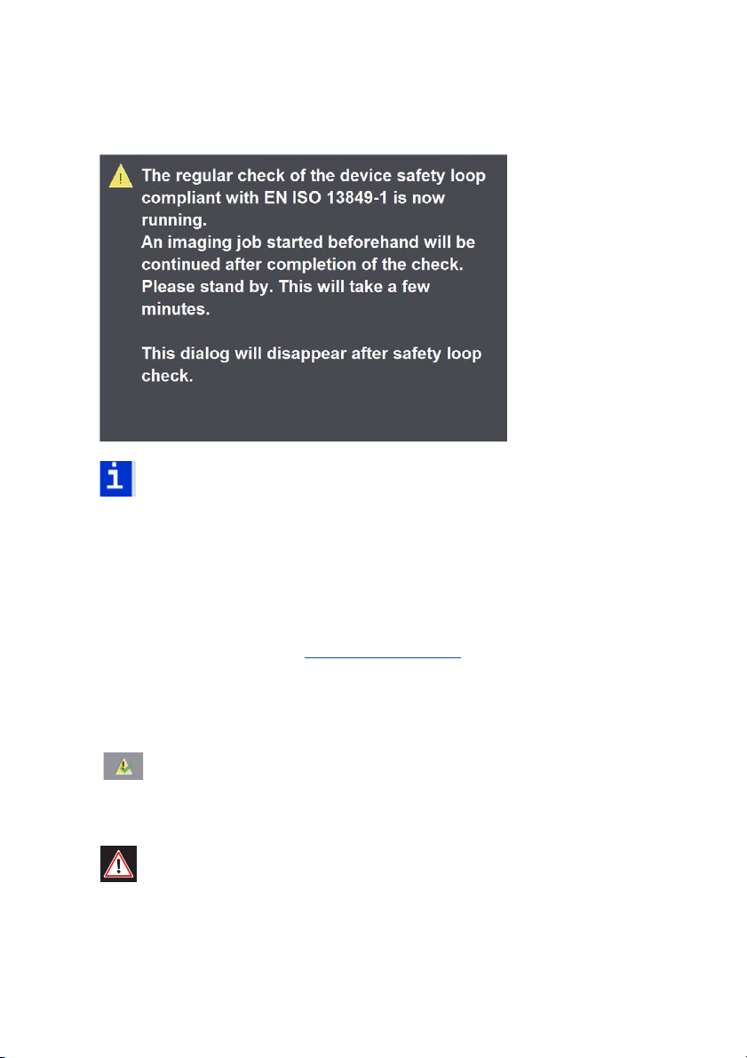
During the startup, a window displays on the CTP User Interface, pointing out
the check of the safety loop.
14 Version 2019
Before you start ...
Note: During the check of the safety loop, it is not possible to image
plates.
The window closes automatically as soon as the check is finished (this can take
some minutes).
Manual check of the safety loop
The user can run an early check of the safety loop at any time before the 24hour time limit expires (see
moment in production allows this.
Start check of safety loop
The check of the safety loop starts after you click this button in the
user interface and confirm again.
Caution: During the test no imaging jobs may be processed! In other
words, no plates must be in the device and no jobs are waiting for processing. You must stop processing beforehand.
Suprasetter 145/162/190 – User’s Guide 15
"Timeframe", page 16) if, for example, a suitable

Before you start ...
Timeframe
This displays the interval until the next regular safety loop
test.
ESD Protective Measures for Prepress Systems and Operators
Basics
Devices from Heidelberger Druckmaschinen AG are resistant to electrostatic
discharges (within the limits of EN 55024:2001).
In order to protect devices and users from being unnecessarily exposed to such
discharges, we have listed a few tips below that will help reduce the frequency
and intensity of the discharges.
Formation
In a prepress environment, this physical phenomenon occurs most frequently
as a result of triboelectricity. In such cases, electrostatic charges are generated
when bodies that have close contact are separated.
16 Version 2019

Before you start ...
Examples:
• Walking across non-conductive (insulating) flooring (e.g. synthetic floor
covering)
• Removing the slip sheet from the plate
• Getting up off a seat
The intensity of these charges is determined basically by the following parameters:
• Humidity
• Roughness of the material surface
• Pressure/space when in contact
• Conductivity of the materials
Practical Tips
The following practical tips are to help reduce the number and intensity of electrostatic discharges when handling the devices:
• Install the devices in rooms that have conductive floor covering.
• Resistance to ground < 1x10
ing does not comply with this requirement in the majority of cases. Pure
concrete flooring generally has a low volume resistance. If you have nonconductive floor covering, the use of ESD mats placed on the operator
side of the devices is recommended. These mats can be obtained from
suppliers. However, in such a case, existing charges are only slowly
reduced depending on the shoes that the personnel wear. For personal
safety, the resistance of floor to ground should not fall below 105 ohms.
9
ohms (IEC/EN 61340-5). Synthetic carpet-
• The humidity at the installation site should not fall below 45% relative
humidity. High air humidity is a decisive factor in preventing the formation of electrostatic charges. For example, a relative humidity of 10 - 20%
will produce 35,000 V when crossing a carpet. This value drops to 1,500
V with a relative air humidity of 65 - 90%.
Suprasetter 145/162/190 – User’s Guide 17

Before you start ...
• Clothing where cotton material is >50%.
• Conductive seating.
• ESD shoes that can be obtained from suppliers and are used on conductive flooring help further to reduce charges when walking across floor
coverings.
Standards/Sources
More details on this subject can be found in the following sources:
• IEC / EN 61340-5 (Protection of electronic devices from electrostatic
phenomena - General Requirements)
• Electrostatic Discharge Association
http://www.esda.org/
• Electrostatic Society of America
http//www.electrostatics.org
Disposal of the Suprasetter 145/162/190
The disposal of the Suprasetter 145/162/190 is described in chapter Disposal.
Converting the Suprasetter 145/162/190
Any conversion work on the Suprasetter 145/162/190 may be performed only
by Heidelberg service personnel.
18 Version 2019

Before you start ...
i
i
About This Documentation
This documentation is intended as a reference work for the operator during
training courses and in operation.
Note: The documentation must be kept safely for future use right up to
the disposal of the Suprasetter.
What You Should Already Know
The user, having attended a training course, should be familiar with the Suprasetter.
Further Documentation
You can find more information in the following documentation:
• Prinect MetaDimension - User's Guide/Workflow
• Prinect Integration Manager - User's Guide/Workflow
Suprasetter 145/162/190 – User’s Guide 19

Symbols and Styles
The following typographical conventions are used in this manual:
• References to other chapters and sections are
underlined.
blue (on the screen) and
Example: See
• Quotes are used to indicate menus, folders, functions, hardware conditions, switch settings, system messages, etc.
Example: Set the switch to "off".
• Menus, functions and sub-functions are separated by ">".
Example: Select "File > Open...".
• Buttons which you should hold down simultaneously are connected with
a plus character.
Example: Press Alt+A.
section "Symbols and Styles", page 20.
Before you start ...
i
i
Important Information
Important information in the text is indicated by symbols at the side which are
used as follows:
Warning: Contains information that must be taken into consideration to
protect the user from injury.
Caution: Contains information that must be taken into consideration to
prevent damage to hardware or software.
Note: Contains important general or additional information on a specific topic.
Prerequisite: Lists requirements which must be fulfilled before the
steps which follow can be performed.
Heidelberg online
Do you have questions concerning our products?
Do you want to improve your workflows?
Then visit us on the Internet. You can find us at:
http://www.heidelberg.com/
Suprasetter 145/162/190 – User’s Guide 21


Introduction
Introduction
Description of the Unit and its Functions
The Suprasetter is a high-speed computer-to-plate imaging device for large-format plates.
It images thermal printing plates in daylight operation. The Suprasetter
receives screened data from the RIP for imaging onto printing plates. On a
manual device or semi-automatic device, the plates are placed manually onto
the insertion table or, in the case of a fully automated device, they are loaded
by the cassette magazine. The Suprasetter automatically loads the plate onto
the drum, images it, punches it (option) and conveys the imaged plate back to
the insertion table or to the connected ejection table.
The Suprasetter can be shipped and installed in various versions:
• As a manual device. The plates are inserted and ejected at the front of the
device.
• As a semi-automatic device with manual plate feed at the front. The
plates are ejected at the rear of the device to an ejection table that conveys them straight ahead, to the right or to the left.
• As a fully automated device, with the plates ejected at the front of the
device to an ejection table that conveys them straight ahead, to the right
or to the left.
Suprasetter 145/162/190 – User’s Guide 23
Introduction
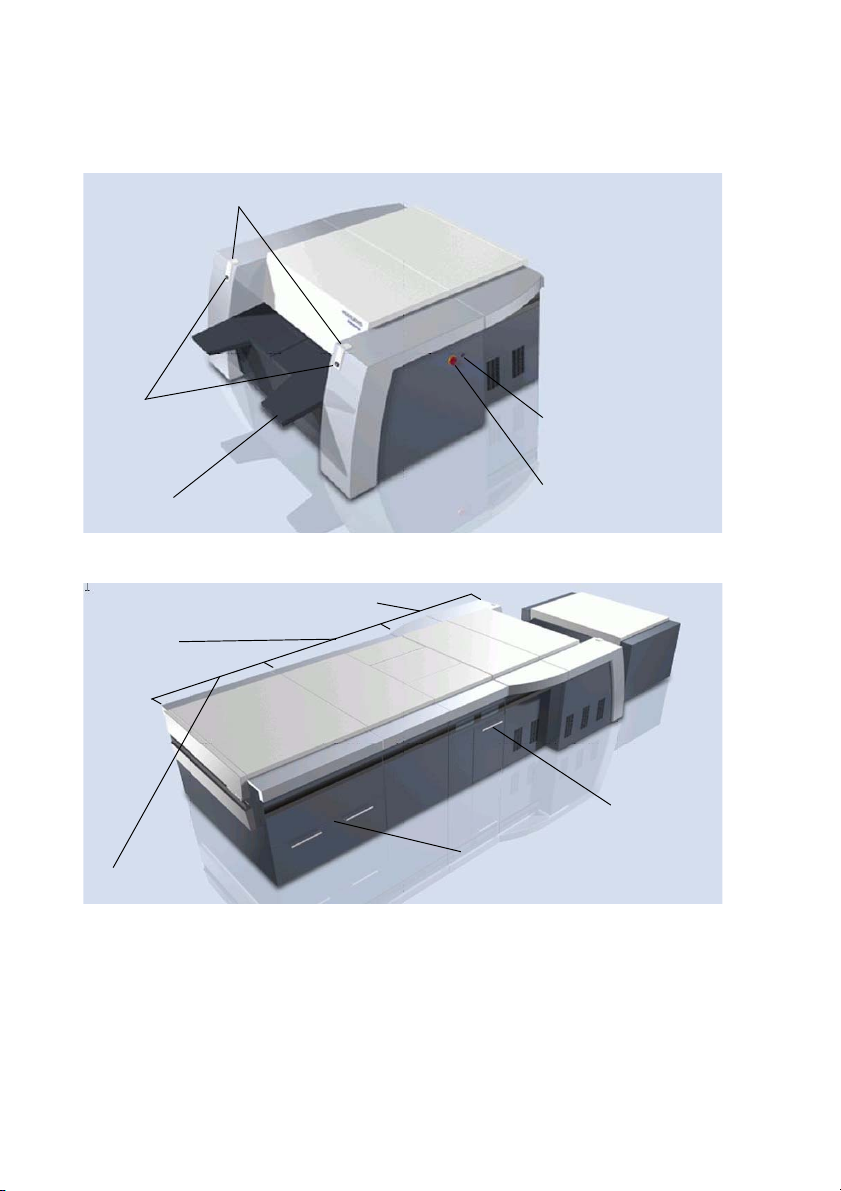
Status LEDs
Load buttons
Insertion table
On/Off button
Power switch
Separator
Recorder
OLP
Cassette magazine
Drawer for plate trays
Waste box
Operating elements on the manual device and on the semi-automatic device
Additional functional groups and operating units on the fully automated device
Status LEDs
The following actions of the Suprasetter are indicated by the status LEDs:
24 Version 2019
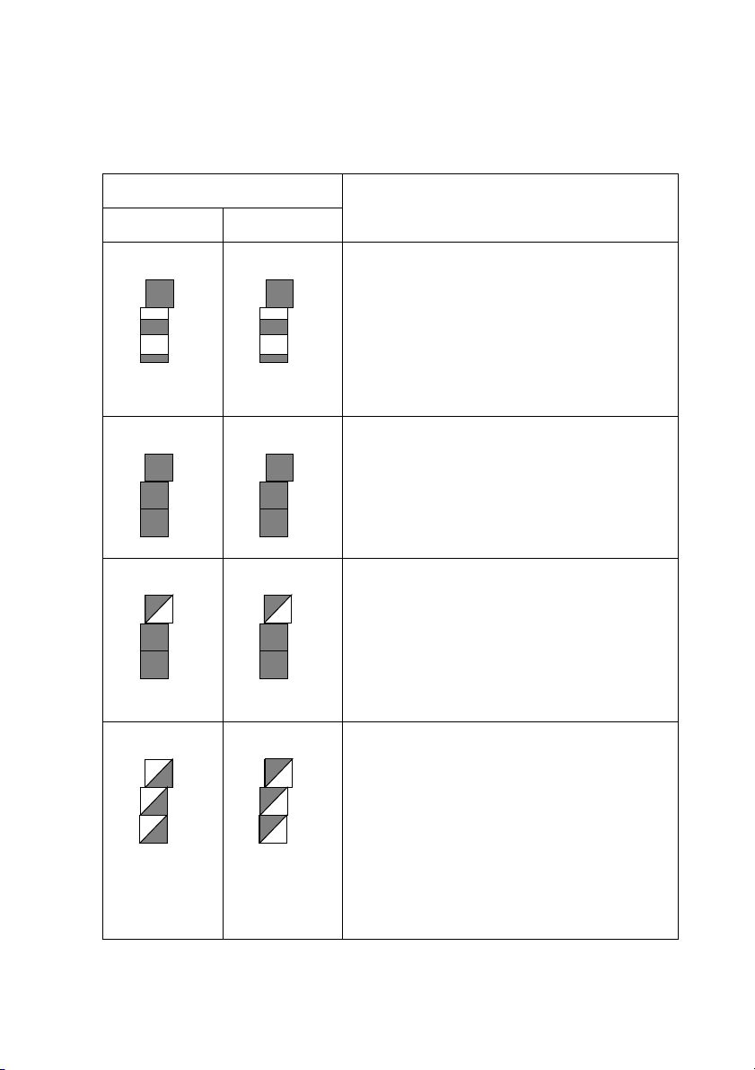
Status Panel Event
Left half Right half
Startup:
The Suprasetter starts the software and initializes the hardware.
The status LEDS are like level indicators filling up from bottom to top, running parallel
on both sides, until normal operation is
reached.
Standby:
The Suprasetter is ready to image a plate but
is not busy imaging at that moment.
All LEDs light up.
Normal operation:
Introduction
The Suprasetter is presently imaging a plate
or otherwise busy, for example, it is unloading a plate to the online processor or loading
a plate from the Autoloader.
The top LEDs flash synchronously.
Error:
An error occurred that must be eliminated by
the user.
The LEDs on each level flash, alternating
between left and right. A beep also indicates
the error status.
The user must go to the GUI of the Suprasetter to learn more details about the error.
Suprasetter 145/162/190 – User’s Guide 25
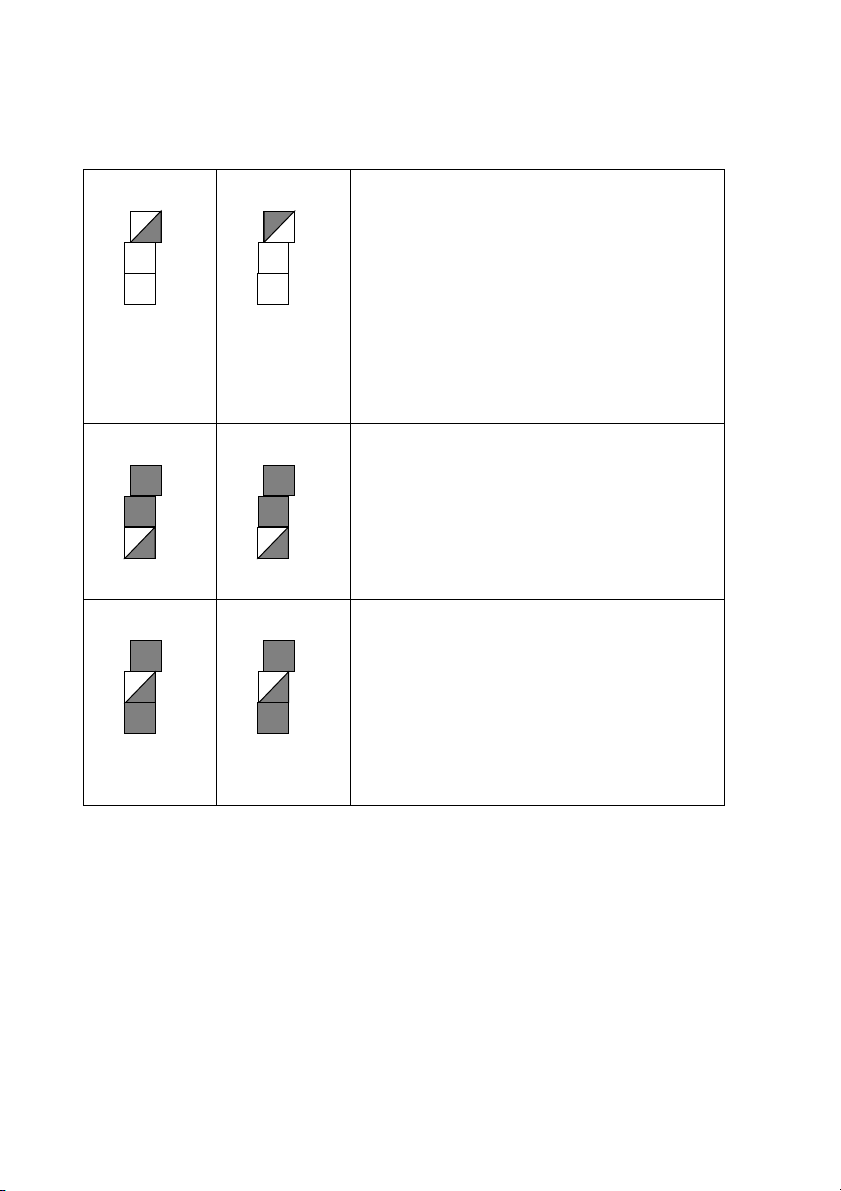
Introduction
Waiting:
The Suprasetter is waiting for something
within it (e.g. until the operating temperature
is reached) or is waiting for a connected
device (online processor or the cassette
loader).
The top LEDs flash alternately. A brief beep is
also heard if an operator intervention is
required.
Waiting for a plate:
The user is prompted to insert the required
plate.
The bottom LEDs flash synchronously. A brief
beep is also heard.
Plate ready to be removed:
You will hear a beep approx. 3 seconds
before an imaged plate appears. In addition,
the middle LEDs flash synchronously.
When the plate is output, you will hear a
brief beep again, indicating that the plate
can now be removed.
Power switch
You can disconnect the device fully from the power supply with the power
switch, for example, for maintenance work. You can switch on the device only
when the power switch is set to 'I'.
26 Version 2019

On/Off button
i
i
The On/Off button allows you to:
• switch on the Suprasetter, see
34.
Introduction
section "Switching on the Device", page
• switch off the Suprasetter, see
36.
• switch off the beep that sounds, for example, after a malfunction occurs.
section "Switching Off the Device", page
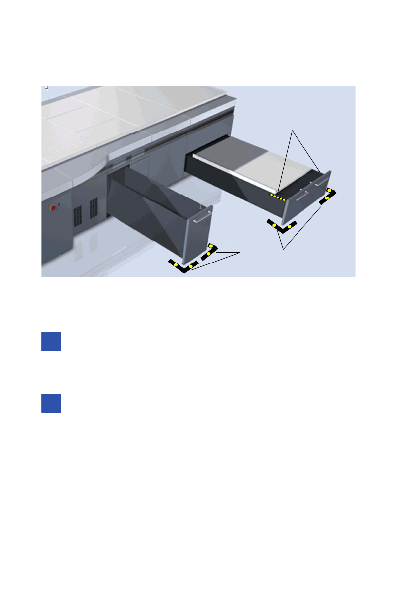
Keeping Access Routes Clear
If an access route runs parallel to the device, with staff passing by the device
several times a day, then the end of the required floor space is to be marked
off by black-and-yellow tape to keep this space clear.
Note: Local regulations on keeping access routes clear must also be
complied with.
Suprasetter 145/162/190 – User’s Guide 27
Introduction
Marking indicating the end
of the required floor space
Markings on both sides of
the magazine drawer
i
i
i
i
Notes on the Use of Plates
Note: Only printing plates and slip sheets approved by Heidelberg may
be used in the Suprasetter as only these produce the specified results.
The use of unapproved plates and slip sheets can result in malfunctions.
Note: It is essential that the Suprasetter is fitted with a suction device
(debris removal system) if plates requiring a suction device are to be
used in the Suprasetter.
28 Version 2019

Notes on Installation
i
i
Notes on Installation
Notes on Installation
Transport of the Suprasetter 145/162/190
The Suprasetter 145/162/190 is to be transported solely by companies that are
authorized by Heidelberg to do so. Transport may be done only by qualified
persons. The appropriate transport regulations must be observed during transport..
Installing the Device
The Suprasetter may be installed only by authorized service personnel. The
ambient conditions must be observed.
Warning: In compliance with standard EN 1010-2:2003 # 5.2.1 and
because the installation site must have clean conditions, the
Suprasetter may not be operated in sites where paper is being printed
or paper finishing devices are running.
Note: Initial installation is performed by service personnel. This
includes lifting the unit off the palette and removing the transport safeguards.
Automatic Cutouts
The automatic cutouts are located behind the right side panel. When an automatic cutout is triggered, please proceed as described in the section "Switching on an Automatic Cutout" (page 61). Repairs may be done only by service
personnel.
Suprasetter 145/162/190 – User’s Guide 29

Notes on Installation
Software Installation (Container Version)
Prerequisite:
· The Suprasetter is switched off.
· The workstation is switched on and ready for operation.
· All Windows applications were run down.
· A backup of the recorder configuration is saved, see the section
"Saving a Backup of the Recorder Configuration" (page 41).
· A buffer plate named "Pagebuff" is available and formatted.
Operation:
1. Insert the Suprasetter installation CD into the CD-ROM drive. Setup
starts automatically if Autorun is activated.
2. If Autorun is disabled, you can start the setup by double-clicking
"Setup.exe". The "CTP User Interface Setup" window displays.
3. Click "Next". The "LicenseAgreement" window displays.
4. Accept the licensing agreement and click "Next". The "Choose Destination Location" window displays.
5. Use the suggested path or select the path you want by clicking the
"Browse" button.
6. Click "Next". The "Select Program Folder" window displays.
7. Use the suggested folder or select one from the list or enter a new folder
name.
8. Click "Next", the "Ethernet Address" window displays.
9. Accept the Ethernet address (172.16.0.2) by clicking "Next". The "Start
Copying Files" window displays.
10. Click "Next". The installation procedure is executed. You will see the
"Install Shield Wizard Complete" window at the end of the installation
procedure.
30 Version 2019
 Loading...