

HEIDELBERG Suprasetter 145, Suprasetter 162, Suprasetter 190 Installation Manual

Suprasetter 145/162/190 - Installation
Suprasetter 145/162/190
Suprasetter 145/162/190
Installation
10/2019
Order No. PG.999.0101

ABC
Copyright © 10/2019
Heidelberger Druckmaschinen AG.
No part of this book may be reproduced
without prior written permission.
.. . . . . . . . . . . . . . . . . . . . . . . . . . . . . . . . . . . . . . . . . . . . . . . . . . . . . . . . . . . . . . . . . . . . . . . . . . . . . . . . . . . . . . . . . . . .
Important notice:
We are dedicated to improving and
enhancing our products. Consequently,
the information in this manual is subject
to technical modifications and other
changes without notice.
Heidelberger Druckmaschinen AG.
Kurfürsten-Anlage 52-60
69115 Heidelberg
Germany
Phone +49 6221 92-00
Telefax +49 6221 92-6999
www.heidelberg.com
Heidelberger Druckmaschinen AG
assumes no responsibility for information and description as far as third-party
products are concerned.
The information contained in this manual about performance and speed as
well as technical data concerning application of our products is not legally
binding as it does not constitute a written contract of features.
If any problems occur with the product
described in this manual, please contact
the Heidelberg agency which is responsible for you.
Order No. PG.999.0101
Printed in Germany.

Table of Contents
Table o f Con tent s
Prinect Signa Station 1
Suprasetter 145/162/190 1
Table of Contents
1
Before you start ...
About This Documentation . . . . . . . . . . . . . . . . . . . . . . . . . . . . . . . . . . . . . . . . . . . . . . . 5
Symbols and Styles . . . . . . . . . . . . . . . . . . . . . . . . . . . . . . . . . . . . . . . . . . . . . . . . . . . 5
Important Information . . . . . . . . . . . . . . . . . . . . . . . . . . . . . . . . . . . . . . . . . . . . . . . . . 6
Safety
Safety with Suprasetter 145/162/190 . . . . . . . . . . . . . . . . . . . . . . . . . . . . . . . . . . . . . . . . 7
Intended Use . . . . . . . . . . . . . . . . . . . . . . . . . . . . . . . . . . . . . . . . . . . . . . . . . . . . . . . . 7
General . . . . . . . . . . . . . . . . . . . . . . . . . . . . . . . . . . . . . . . . . . . . . . . . . . . . . . . . . . . . 7
Safety Notes on Installation . . . . . . . . . . . . . . . . . . . . . . . . . . . . . . . . . . . . . . . . . . . . . 7
Power Supply . . . . . . . . . . . . . . . . . . . . . . . . . . . . . . . . . . . . . . . . . . . . . . . . . . . . . . . . 8
Additional Protective Conductor Terminal . . . . . . . . . . . . . . . . . . . . . . . . . . . . . . . . . . . 8
Power Switch with Emergency Stop Function . . . . . . . . . . . . . . . . . . . . . . . . . . . . . . . 10
Automatic Cutouts . . . . . . . . . . . . . . . . . . . . . . . . . . . . . . . . . . . . . . . . . . . . . . . . . . . . 11
Mechanical Hazards . . . . . . . . . . . . . . . . . . . . . . . . . . . . . . . . . . . . . . . . . . . . . . . . . . . 11
Laser safety . . . . . . . . . . . . . . . . . . . . . . . . . . . . . . . . . . . . . . . . . . . . . . . . . . . . . . . . . 12
Definitions . . . . . . . . . . . . . . . . . . . . . . . . . . . . . . . . . . . . . . . . . . . . . . . . . . . . . . . . 12
General . . . . . . . . . . . . . . . . . . . . . . . . . . . . . . . . . . . . . . . . . . . . . . . . . . . . . . . . . . . 12
Laser Standards and Regulations . . . . . . . . . . . . . . . . . . . . . . . . . . . . . . . . . . . . . . . . 12
Service and Maintenance . . . . . . . . . . . . . . . . . . . . . . . . . . . . . . . . . . . . . . . . . . . . . 12
Laser Safety Goggles . . . . . . . . . . . . . . . . . . . . . . . . . . . . . . . . . . . . . . . . . . . . . . . . . 13
Standards . . . . . . . . . . . . . . . . . . . . . . . . . . . . . . . . . . . . . . . . . . . . . . . . . . . . . . . . . . 13
Radio Interference Suppression . . . . . . . . . . . . . . . . . . . . . . . . . . . . . . . . . . . . . . . . . . 15
Approvals and Conformity . . . . . . . . . . . . . . . . . . . . . . . . . . . . . . . . . . . . . . . . . . . . . . 15
Safety Loop . . . . . . . . . . . . . . . . . . . . . . . . . . . . . . . . . . . . . . . . . . . . . . . . . . . . . . . . . 15
Hold-to-Run Button . . . . . . . . . . . . . . . . . . . . . . . . . . . . . . . . . . . . . . . . . . . . . . . . . . . 16
Procedure . . . . . . . . . . . . . . . . . . . . . . . . . . . . . . . . . . . . . . . . . . . . . . . . . . . . . . . . . 17
Service Switch . . . . . . . . . . . . . . . . . . . . . . . . . . . . . . . . . . . . . . . . . . . . . . . . . . . . . . . 17
Cleaning . . . . . . . . . . . . . . . . . . . . . . . . . . . . . . . . . . . . . . . . . . . . . . . . . . . . . . . . . . 18
Harmful Substances . . . . . . . . . . . . . . . . . . . . . . . . . . . . . . . . . . . . . . . . . . . . . . . . . . . 19
Disposal . . . . . . . . . . . . . . . . . . . . . . . . . . . . . . . . . . . . . . . . . . . . . . . . . . . . . . . . . . . 19
Glycol coolant . . . . . . . . . . . . . . . . . . . . . . . . . . . . . . . . . . . . . . . . . . . . . . . . . . . . . . 19
Closed Refrigerant Circuit in the Chiller . . . . . . . . . . . . . . . . . . . . . . . . . . . . . . . . . . . . 19
Overview of Labels . . . . . . . . . . . . . . . . . . . . . . . . . . . . . . . . . . . . . . . . . . . . . . . . . . . 20
Mounting locations . . . . . . . . . . . . . . . . . . . . . . . . . . . . . . . . . . . . . . . . . . . . . . . . . 20
Suprasetter 145/162/190 – Installation 1

Table of Contents
Labels . . . . . . . . . . . . . . . . . . . . . . . . . . . . . . . . . . . . . . . . . . . . . . . . . . . . . . . . . . . 27
Safety with Heidelberg Remote Service . . . . . . . . . . . . . . . . . . . . . . . . . . . . . . . . . . . . . . 34
Heidelberg Remote Service . . . . . . . . . . . . . . . . . . . . . . . . . . . . . . . . . . . . . . . . . . . . 34
Safety Precautions During Remote Control . . . . . . . . . . . . . . . . . . . . . . . . . . . . . . . . . 34
General . . . . . . . . . . . . . . . . . . . . . . . . . . . . . . . . . . . . . . . . . . . . . . . . . . . . . . . . . . . 36
Remote Control Procedure . . . . . . . . . . . . . . . . . . . . . . . . . . . . . . . . . . . . . . . . . . . . . 36
Access to Machine Components
Machine Components Suprasetter 145/162/190 . . . . . . . . . . . . . . . . . . . . . . . . . . . . . . . 39
Suprasetter 145/162/190 . . . . . . . . . . . . . . . . . . . . . . . . . . . . . . . . . . . . . . . . . . . . . . 39
Access to the Components . . . . . . . . . . . . . . . . . . . . . . . . . . . . . . . . . . . . . . . . . . . . . 40
Installation Preparation
General . . . . . . . . . . . . . . . . . . . . . . . . . . . . . . . . . . . . . . . . . . . . . . . . . . . . . . . . . . . . 43
Floor Properties . . . . . . . . . . . . . . . . . . . . . . . . . . . . . . . . . . . . . . . . . . . . . . . . . . . . . . 43
Machine's Arrival at the Customer's . . . . . . . . . . . . . . . . . . . . . . . . . . . . . . . . . . . . . . . 44
Protection Against Corrosion . . . . . . . . . . . . . . . . . . . . . . . . . . . . . . . . . . . . . . . . . . . 45
Provision of a Power Cable . . . . . . . . . . . . . . . . . . . . . . . . . . . . . . . . . . . . . . . . . . . . 45
Plate Material . . . . . . . . . . . . . . . . . . . . . . . . . . . . . . . . . . . . . . . . . . . . . . . . . . . . . . . . 46
Special-Purpose Tools . . . . . . . . . . . . . . . . . . . . . . . . . . . . . . . . . . . . . . . . . . . . . . . . . . 47
Installation
Overview: Chassis Alignment . . . . . . . . . . . . . . . . . . . . . . . . . . . . . . . . . . . . . . . . . . . . 49
Setting up the Units . . . . . . . . . . . . . . . . . . . . . . . . . . . . . . . . . . . . . . . . . . . . . . . . . . . . 50
Setting up the Imaging Unit . . . . . . . . . . . . . . . . . . . . . . . . . . . . . . . . . . . . . . . . . . . . 50
Remove the remaining transport safeguards . . . . . . . . . . . . . . . . . . . . . . . . . . . . . . . . . 55
Plate Loader . . . . . . . . . . . . . . . . . . . . . . . . . . . . . . . . . . . . . . . . . . . . . . . . . . . . . . . 60
Chiller Connection . . . . . . . . . . . . . . . . . . . . . . . . . . . . . . . . . . . . . . . . . . . . . . . . . . . . . 68
Establish connections . . . . . . . . . . . . . . . . . . . . . . . . . . . . . . . . . . . . . . . . . . . . . . . . . . . 71
EMC and Ground Connections . . . . . . . . . . . . . . . . . . . . . . . . . . . . . . . . . . . . . . . . . . . 71
Data cable to plate loader . . . . . . . . . . . . . . . . . . . . . . . . . . . . . . . . . . . . . . . . . . . . . . 72
Plate loader power connection . . . . . . . . . . . . . . . . . . . . . . . . . . . . . . . . . . . . . . . . . . . 73
Lexium 05 (3-phase) . . . . . . . . . . . . . . . . . . . . . . . . . . . . . . . . . . . . . . . . . . . . . . . . . 73
Lexium 32 (3-phase) . . . . . . . . . . . . . . . . . . . . . . . . . . . . . . . . . . . . . . . . . . . . . . . . . 74
Lexium 32 (3-phase + N) . . . . . . . . . . . . . . . . . . . . . . . . . . . . . . . . . . . . . . . . . . . . . 75
Secure the cover plate above the power supply . . . . . . . . . . . . . . . . . . . . . . . . . . . . . . 76
2

Table of Contents
Plate loader compressed air . . . . . . . . . . . . . . . . . . . . . . . . . . . . . . . . . . . . . . . . . . . . 77
Data cable to imaging unit . . . . . . . . . . . . . . . . . . . . . . . . . . . . . . . . . . . . . . . . . . . . . 78
Imaging unit power supply . . . . . . . . . . . . . . . . . . . . . . . . . . . . . . . . . . . . . . . . . . . . . 79
Plate Loader Opto Switches . . . . . . . . . . . . . . . . . . . . . . . . . . . . . . . . . . . . . . . . . . . . 83
External Compressed Air Connection . . . . . . . . . . . . . . . . . . . . . . . . . . . . . . . . . . . . . 84
Laser Module Installation . . . . . . . . . . . . . . . . . . . . . . . . . . . . . . . . . . . . . . . . . . . . . . . 85
Hose connections . . . . . . . . . . . . . . . . . . . . . . . . . . . . . . . . . . . . . . . . . . . . . . . . . . . . 86
Imaging Unit: Laser Module Slots . . . . . . . . . . . . . . . . . . . . . . . . . . . . . . . . . . . . . . . . 90
PC Connection . . . . . . . . . . . . . . . . . . . . . . . . . . . . . . . . . . . . . . . . . . . . . . . . . . . . . . . . 91
External Power Supply . . . . . . . . . . . . . . . . . . . . . . . . . . . . . . . . . . . . . . . . . . . . . . . . 93
Software . . . . . . . . . . . . . . . . . . . . . . . . . . . . . . . . . . . . . . . . . . . . . . . . . . . . . . . . . . . . 96
Network Adapter Configuration . . . . . . . . . . . . . . . . . . . . . . . . . . . . . . . . . . . . . . . . . . 96
Installing recorder software . . . . . . . . . . . . . . . . . . . . . . . . . . . . . . . . . . . . . . . . . . . 103
Filling the Chiller . . . . . . . . . . . . . . . . . . . . . . . . . . . . . . . . . . . . . . . . . . . . . . . . . . . . . 105
Configuring and testing the system . . . . . . . . . . . . . . . . . . . . . . . . . . . . . . . . . . . . . . . . 107
Configure the System and set Installation-specific Parameters . . . . . . . . . . . . . . . . . . . 107
Testing . . . . . . . . . . . . . . . . . . . . . . . . . . . . . . . . . . . . . . . . . . . . . . . . . . . . . . . . . . 108
Concluding Work . . . . . . . . . . . . . . . . . . . . . . . . . . . . . . . . . . . . . . . . . . . . . . . . . . . . . 108
Check Tension of Drive Toothed Belt on Imaging Unit . . . . . . . . . . . . . . . . . . . . . . . . . 110
Optional Components
OLP Conveyor . . . . . . . . . . . . . . . . . . . . . . . . . . . . . . . . . . . . . . . . . . . . . . . . . . . . . . . . 113
Cross Conveyor . . . . . . . . . . . . . . . . . . . . . . . . . . . . . . . . . . . . . . . . . . . . . . . . . . . . . . . 114
Suprasetter 145/162/190 with APL . . . . . . . . . . . . . . . . . . . . . . . . . . . . . . . . . . . . . . . . . 116
Technical Data
Technical Data of Suprasetter 145/162/190 . . . . . . . . . . . . . . . . . . . . . . . . . . . . . . . . . . 125
Index
Suprasetter 145/162/190 – Installation 3


Before you start ...
Before you start ...
About This Documentation
This documentation applies to Suprasetter 145/162/190.
The Suprasetter 145/162/190 is a laser imagesetter for imaging offset printing plates.
Symbols and Styles
The following typographical conventions are used in this manual:
• References to other chapters and sections are blue (on the screen) and underlined.
Example: See section "Symbols and Styles", page 5.
• Quotes are used to indicate menus, folders, functions, hardware conditions, switch settings, system messages, etc.
Example: Set the switch to "off".
• Menus, functions and sub-functions are separated by ">".
Example: Select "File > Open...".
• A plus sign is used to indicate that several keys have to be pressed at the same time.
Example: Press Alt+A.
Suprasetter 145/162/190 – Installation 5

Before you start ...
i
i
Important Information
Important information in the text is indicated by symbols at the side which are used as follows:
DANGER
The "DANGER" signal word indicates a hazard with a high risk which, if not
avoided, will result in death or severe injury.
WARNING
The "WARNING" signal word indicates a hazard with a medium risk which, if not
avoided, can result in death or severe injury.
CAUTION
The "CAUTION" signal word indicates a hazard with a low risk which, if not
avoided, can result in minor or moderate injury.
NOTICE
The "NOTICE" signal word indicates possible material damage. Non-observance
of this notice can cause damage to the machine.
Note: Contains important general or supplementary information about a specific topic.
Prerequisite: Lists requirements which must be fulfilled before the steps which follow can
be performed.
6

Safety
Safety
Safety with Suprasetter 145/162/190
Intended Use
The Suprasetter is a laser imagesetter with an optional fully automatic loader and transport table to
the on-line processor, for imaging offset printing plates and may only be used for this purpose as
described in the operating instructions.
Heed the safety notes in the related documentations when you connect optional components.
Do not place any objects or liquids on the device.
Ventilation outlets must be kept clear at all times.
General
Service work may be performed only by authorized personnel specialized in this field. The respective
accident prevention regulations must be observed.
Failure to observe the safety regulations may result in the loss of accident insurance!
Unauthorized opening of housing parts and improper repairs not expressly described in the operating
instructions or service documentation can lead to considerable danger for the user (crushing by mov
ing parts or injuries by electric shocks or, in the case of the Suprasetter, injuries through invisible
high-power laser radiation).
Follow the specified operational sequence when removing covers or other housing parts.
Risk of injury from sharp edges
Plate edges can be sharp. You can injure your hands if you do not wear protective gloves. Put on protective gloves!
Safety Notes on Installation
The Suprasetter, including the fully automatic loader and transport table to the processor when they
are used, may only be installed by authorized service personnel. The ambient conditions must be
observed in this process.
Connectors and outlets of the house installation must be easily accessible so that, in the event of an
emergency, for example, the unit can be completely disconnected from the power supply by switching
off the main switch or by pulling out the power plug (if present).
-
The unit must be in a de-energized state when connecting the data cables. Connect the power cables
of
all other devices only after the data cables are connected. This will protect you from a fatal electric shock. It will also protect the electronics of the units from failure caused by voltage impulses following potential differences.
Make sure to lay cables and hoses so no-one can trip over them!
Suprasetter 145/162/190 – Installation 7

Safety
i
i
For the operating company of a print shop, it is important that the exposure limits regarding breathable air in the work area (where the platesetter is located) are adhered to. The air exchange must be
arranged in such a way that the measured dust particles are regularly below the exposure limit val
ues. In accordance with the state of the art, this can be achieved with an 8 to 10 air change rate per
hour. If this is not the case at the installation site, the operating company should install an additional
exhaust system.
When installing the machine, pay attention to the information in the "Installation" and "Technical
Data" chapters.
In order to provide proper ventilation, ensure that there is sufficient distance between the machine
and the wall or between the machine sides and other equipment when the equipment is installed.
The machine
- should not be installed in the proximity of air conditioning facilities,
- must be protected against direct sunlight or spotlights fitted in the room,
- must be protected against moisture.
In order to meet radio interference suppression requirements, only screened data cables may be
used.
-
Because of product safety requirements and because the installation site must have clean conditions,
the Suprasetter may not be operated in sites where paper is being printed or paper finishing devices
are running.
The Suprasetter may be switched on only if the ambient temperature is higher than 15 °C. Temperatures lower than this can cause damage to the components!
The required ambient conditions (see "Technical Data", page 125 chapter) must be observed for at
least 12 hours after power-off so that the Suprasetter is not damaged by condensation.
Power Supply
The Suprasetter is connected to the inhouse power supply either permanently with terminal block X1
and the 5-wire power cable or with a 5-pin connector that must be designed for connection to 400V/
16A (USA: 400V/15A) AC.
The respective national regulations must be observed if power cables are used that were not supplied
by Heidelberger Druckmaschinen AG or if connectors are modified. In the EU and in the extended
area of validity of IEC 60204-1 (for latest version, see
tion of the protective conductor must be 10 mm² for a leakage current of 10 mA and higher. The protective conductor current of this device is approx. 70 mA.
Table Electrical Safety), the minimum cross sec-
Additional Protective Conductor Terminal
Note: After installation, the protective earth connection must be tested.
8

Fig. 1 PE terminal
Safety
Since the leakage current is >10 mA, it is mandatory to connect the protective earth (PE) wire in
the power cable
conductor cable. A separate PE cable (green-andyellow or only green) with a cable cross-section of
at least 6 mm² must be routed parallel to the
power cable.
On the Suprasetter, it must be connected to the
power supply group at its designated PE2 terminal
(
Fig. 2/1).
and the additional protective
Fig. 2 Power supply group PE2
At the service tap, it must be connected to a separate PE terminal (Fig. 1/1). In addition, you must
make sure that the PE is routed further in the service tap with a cable cross section of at least
10
mm².
Suprasetter 145/162/190 – Installation 9
Safety
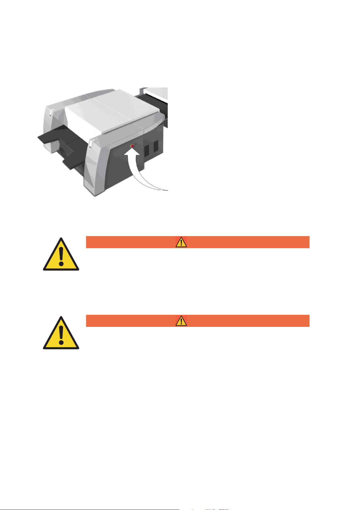
Power Switch with Emergency Stop Function
The power switch (Fig. 3) triggers an all-pole cutoff of the Suprasetter and the fully automatic
loader from the power supply. In an emergency,
this power switch is used as an emergency stop
switch for the Suprasetter and the automatic
loader. The power switch with emergency stop
function is located on the right side of the Supra
setter.
-
Fig. 3 Suprasetter
WARNING
Risk of injury from improper operation during an emergency stop
The emergency stop circuits of Suprasetter machines are not connected to the
emergency stop circuit of the online processor!
Press the emergency stop on the online processor to stop the online processor.
WARNING
Danger! High Voltage!
The 4 impact buttons with red caps in the Suprasetter are emergency stop buttons. They stop all movements but do not cut off the electric power.
Do not touch any live parts.
10
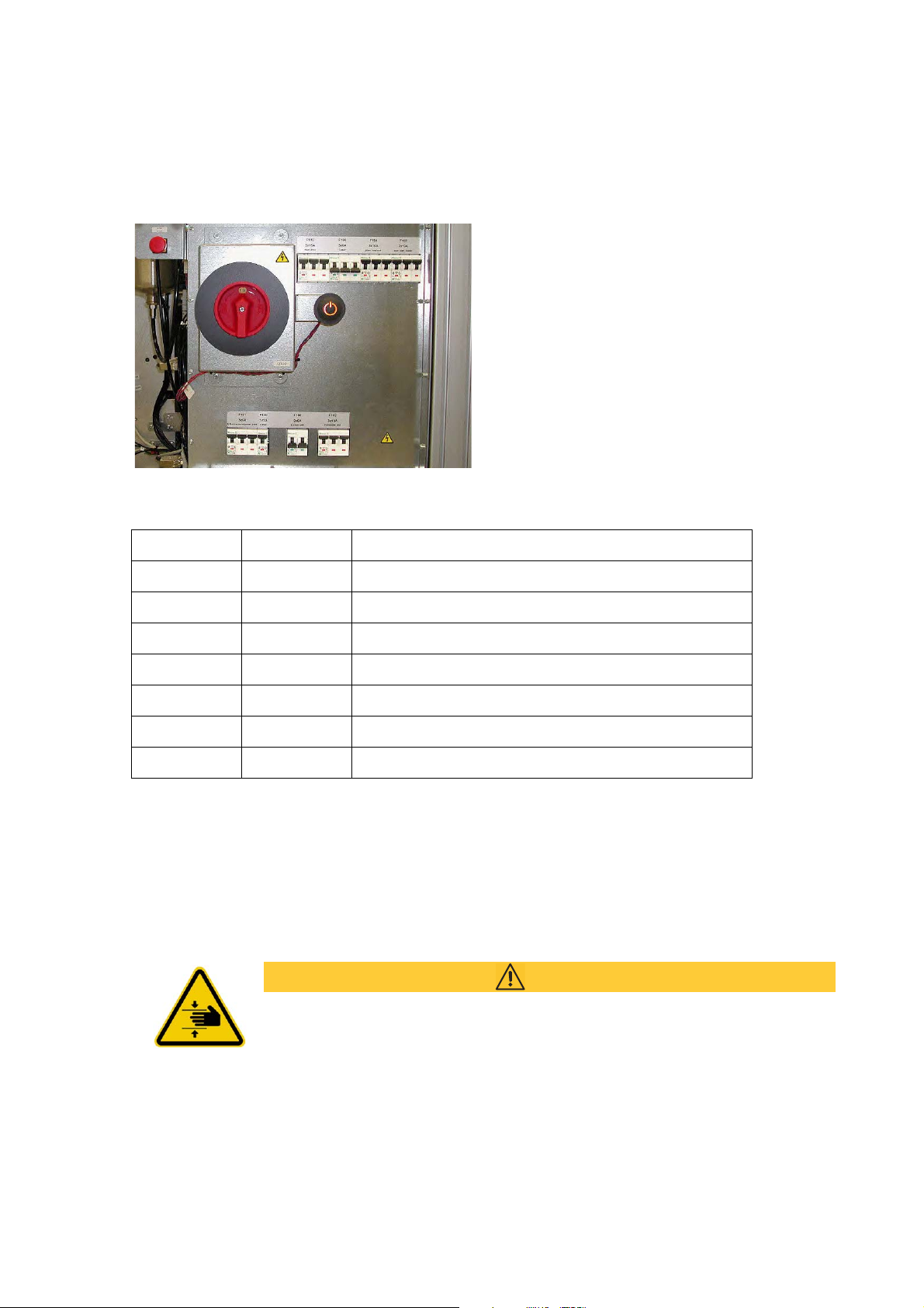
Automatic Cutouts
Fig. 4 Automatic cutouts
Safety
The automatic cutouts are located near the main
switch behind the right cover.
F100 1x 3A Electronics box (standby)
F101 3x 6A Electronics box, imaging unit
F102 3x 13A Chiller
F103 3x 10A Power connection for optional Autoloader
F104 3x 10A Plate Loader
F110 3x 15A Main drive (plate cylinder)
F160 3x 6A Laser system
F190 2x 6A Suction device
Tab. Assignment of automatic cutouts
Mechanical Hazards
CAUTION
Beware of moving parts in the Suprasetter
Risk of squeezing in the area of the lifting tables traveling up and down, in the
path traveled by the laser carriage and by the rotating drum when the covering is
open and the safety loop is bridged by the key-operated switch and the hold-torun button has been pressed.
Switch off Suprasetter during work in these areas.
Suprasetter 145/162/190 – Installation 11

Safety
i
i
Laser safety
Definitions
Laser equipment (product) Equipment with a laser system
Laser device (system) Laser with laser power supply module
Tab. Laser definitions
General
The present laser imagesetter is a Class 1 laser product. This means that the invisible laser radiation
generated in the unit is screened by protective covers. When used correctly, users and Service per
sonnel are never subjected to a risk due to laser beams.
The laser systems used in the Suprasetter are Class 4 products (> 500 mW). Companies servicing the
equipment in Germany must appoint a laser protection officer in compliance with the Accident Pre
vention Regulations (BGV B2) of the Professional Trade Association.
-
-
Note: Servicing may only be carried out by Heidelberg personnel who have been trained by
appropriate laser protection officers for this purpose.
WARNING
Risk of injury from laser radiation
You may be exposed to dangerous radiation by the invisible high-power laser
beams if you use operating or adjustment equipment other than those mentioned
in this document or if you follow other working procedures.
Keep exactly to the described procedures.
Laser Standards and Regulations
The Suprasetter complies with the applicable safety regulations. It is manufactured in accordance
with the German Accident Prevention Regulations (BGV B2) and the EN 60825-1, IEC 60825-1 ("Radi
ation safety of laser equipment") and 21 CFR 1040 (USA) standards.
Service and Maintenance
-
Service work may be performed solely by persons authorized by Heidelberg to do so. When performing the work described in the operating instructions and service manual, the service personnel must
adhere to the described work sequence under any circumstances. Protection from invisible laser radi
ation is ensured by covers or safety loops. Never bypass the laser safety loop (see also section "Safety
Loop", page 15)!
Upon completion of the repair, the functionality of the safety circuits must be checked.
12
-

Safety
i
i
i
i
During reassembly, the protective covers must be checked for completeness. Make sure that these
covers do not show any cracks or other damages.
Note: When the safety switches are open, the key switch can only bypass the safety loop
for the powered movements. The laser safety loop is not bridged as this is not necessary.
Note: A hold-to-run button is also required for operating the drives for the imaging cylinder
and the lift tables when the key-operated switch is activated (see also section "Hold-to-Run
Button", page 16).
WARNING
Caution: Remote Control
If Remote Control is run when the key-operated switch is actuated, make sure to
follow the information about
"Heidelberg Remote Service", page 34.
Laser Safety Goggles
Laser safety goggles do not have to be worn as this is not necessary. Laser adjustments are not to be
made on the Suprasetter as the modules are adjusted at the factory and are to be used without any
additional adjusting.
Standards
This device complies with the safety regulations of the standards listed below.
Product Safety
Act
2006/95/EC Low-voltage directive Europe
2006/42/EC EC directive relating to machinery Europe
2004/108/EC EMC directive Europe
EMVG Act on the electromagnetic compatibility of manufacturing
Tab. General safety
Product Safety Act (2011) Germany
Europe
equipment (2008)
Suprasetter 145/162/190 – Installation 13
Safety
EN ISO 12100 Safety of machines Europe
EN 1010-2 Safety of prepress machines Europe
2006/42/EC EC directive relating to machinery Europe
UVV Accident prevention regulation Germany
IEC 68-2-6 Shock test International
IEC 68-2-27 Shock test International
Tab. Mechanical Safety
EN ISO 13849-1:2008 Europe
EN 60204-1: 2006 Europe
IEC 60204-1: 2005 International
EN 60950-1: 2006 Europe
IEC 60950-1: 2005 International
UL 60950-1: 2007 USA
CSA C22.2 No. 60950-1: 2007 Canada
Tab. Electrical Safety
EN 61000-6-4:2007 Europe
EN 61000-3-2: 2006 Europe
EN 61000-3-3:1995 + A1:2001 + A2:2005 Europe
FCC CFR 47, Part 15, Subpart B, Class A USA
ICES-003, Class A Canada
CISPR 22:2006 Australia/New Zealand
Tab. Interference emission (stray radiation and interference voltage)
EN 61000-6-2: 2005 Europe
Tab. Interference immunity
BGV B2 Germany
EN 60825-1: 2007 Europe
IEC 60825-1: 2007 International
21 CFR 1040 USA
Tab. Laser Safety
14
Safety
Radio Interference Suppression
To comply with directive 2004/108/EC on electromagnetic compatibility, the unit is to be operated
only with all covers correctly installed.
When you connect other electrical equipment to this unit by following the instructions given by the
manufacturer of this equipment, follow the regulations regarding correct installation and mainte
nance to ensure compliance with the radio interference suppression regulations.
Compliance with radio interference suppression regulations can be assumed when the equipment in
question is marked with the European Union mark of conformity (CE) and the instructions for instal
lation, operation and servicing are followed.
-
Approvals and Conformity
GS certified Germany
CE Declaration of Conformity Europe
cETLus certified USA / Canada
CDRH Accession-No. (submitted) USA
FCC CFR 47 Part 15,
Subpart B, Class A
GOST-R certified Russia
ACN 004 395 779 Australia
Tab. Approvals and conformity
USA
-
Safety Loop
The Suprasetter is equipped with a safety loop. If the safety loop is interrupted by opening a cover,
for example, all mechanical motions are stopped and the laser is switched off.
Suprasetter 145/162/190 – Installation 15
Safety
WARNING
Risk of injury if safety system bypassed
The safety system must never be bridged because this could lead to eye
and skin injuries due to the invisible high power laser beam, bruising
caused by the optics or plate carriage, the lifting tables and the drum or
critical injuries caused by electric shocks.
We expressly point out that you must not remove the actuators for the
safety switches installed on the panels because of the hazards generated
by moving parts. For this reason, the fastening screws have been secured
with varnish. When you need to readjust any of the actuators, you must
finally seal the screw heads with securing varnish (HD order No.
00.590.0719 for 50 ml of securing varnish, gray).
We also expressly refer to Management Information MMI 00-996-8007
dated March 31, 2005. Never insert actuators into the safety switches in
order to bypass the safety loop while panels are removed.
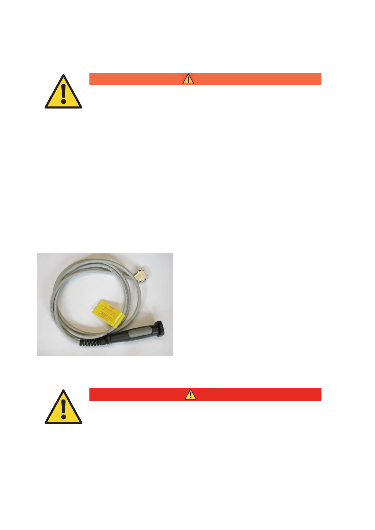
Hold-to-Run Button
Fig. 5 Hold-to-Run Button
Danger! Beware of moving parts! High Voltage!
Never initiate any movements when someone is in the danger area. There must
not be anybody in the machine. No-one must hold his or her head or arm into the
machine. Do not extend the cable of the hold-to-run button to have a better view
of the movement.
Because of the considerable hazard involved,
movements of the imaging cylinder and lift table
are to be enabled only after actuating the hold-torun button as well (for example, to view the move
ments from the outside while the panel is
removed). Releasing or fully pressing down the
button (hand spasm) will immediately stop the
movement.
DANGER
-
16
Safety
i
i
Procedure
You should always heed the following procedure when you want to start mechanical movements with
the hold-to-run button pressed:
1. To move the exposure drum or the lifting tables while the machine is open, you must select this
function via GUI, DIAG or terminal.
2. When prompted to press the Enter key, you must do this within 2 minutes. This will open a 5minute time slot. A single acoustic signal prompts you to press the hold-to-run button now.
3. A double warning signal sounds before the exposure drum or a lifting table start moving. Releasing or fully pressing down the hold-to-run button (hand spasm) or pressing an emergency stop
button will immediately stop the movement. You must then restart the procedure.
4. You must first press the Enter key again if you want to start further mechanical movements after
more than 5 minutes. This is to ensure that at least one person is at the open machine while
movements are running.
Note: The hold-to-run button must always remain with the service staff and must not be
made available to operators.
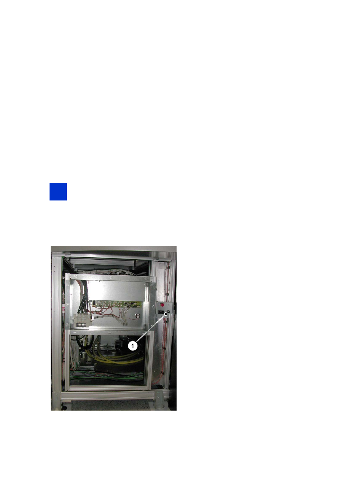
Service Switch
The service technicians switch the Suprasetter to
the Service mode with the service switch (
for testing and maintenance work. This switch is
located on the left-hand side of the Suprasetter
and is only accessible after removing the side
panel on the unit.
The key for this service switch may only be
accessed by authorized service personnel. The
laser is not active in the Service mode; all other
Suprasetter functions are enabled.
Fig. 6/1)
Fig. 6 Service switch in the Suprasetter
Suprasetter 145/162/190 – Installation 17

Safety
WARNING
Risk of injury from improper operation
Only ONE routine cycle may run at a time when you actuate the service switch. A
continuous test must not be carried out. A new procedure must be started sepa
rately and manually.
You cannot remove the keys while the machine is in the service mode. For that reason, it is not possible to refit the side panel as long as the device is in this mode.
WARNING
Risk of injury from improper operation
Only service staff may actuate the service switch and the hold-to-run button.
-
WARNING
Caution: Remote Control
If Remote Control is run when the key-operated switch is actuated, make sure to
follow the information about
Beware of moving parts in the Suprasetter
Pressing the service switch and the hold-to-run button will close the safety loop
that shuts down the mechanical movements. In the service mode, there is a risk
of being crushed in the area around the lift tables traveling up and down, in the
path traveled by the laser carriage and by the rotating drum.
Switch off Suprasetter during work in these areas.
Upon completion of the work, the covers must be refitted to the unit and screwed down.
"Heidelberg Remote Service", page 34.
CAUTION
Cleaning
Always disconnect the Suprasetter by switching off the main switch if liquid cleaning agents are used.
The surfaces of the Suprasetter can be cleaned using a dry cloth. If it is very dirty, it can be cleaned
with a damp cloth which has been dipped in dish-washing liquid and well wrung.
Ensure that no fluids enter the interior of the Suprasetter and keep moisture away from the connector
sockets on the right side of the Suprasetter.
18

Safety
Do not use any abrasive cleaning agents or solvents.
Harmful Substances
When using cleaning and lubricating agents, observe the manufacturer's instructions. If necessary,
consider the safety data sheets, and for Germany the List of Threshold Values quoting the maximum
permissible concentrations (List of Threshold Values issued by the Federal Ministry of Labor and
Social Affairs) as well as the appropriate local regulations.
Disposal
The Suprasetter must be disposed of in compliance with the relevant national regulations. The Suprasetter contains harmful substances. It may not be disposed of together with household waste and
must be handed over to an approved waste disposal company. Addresses can be obtained from the
relevant environmental office.
Glycol coolant
Containers with coolant residues and material used to bind spilled coolant may be incinerated with
household waste.
Waste coolant with an ethylene glycol content of 40-50% must not reach the surface water or the
groundwater.
Undiluted liquids with an ethylene glycol content of ca. 90% must be treated as hazardous waste and
can be incinerated in hazardous waste facilities under consideration of local regulatory stipulations.
See also the "Disposal" chapter in the Suprasetter 145/162/190 - Operation manual.
Closed Refrigerant Circuit in the Chiller
CAUTION
Risk of injury from liquid hazardous to health
The closed refrigerant circuit of the chiller contains the harmful R134a refrigerant
at a maximum pressure of 18.5 bar.
Servicing the refrigerant circuit is permitted in exceptional cases and after con-
sulting the Service in Kiel and even then by specially trained refrigerant technicians. The entire chiller must be replaced if a hot gas valve should be defective.
Suprasetter 145/162/190 – Installation 19
Safety
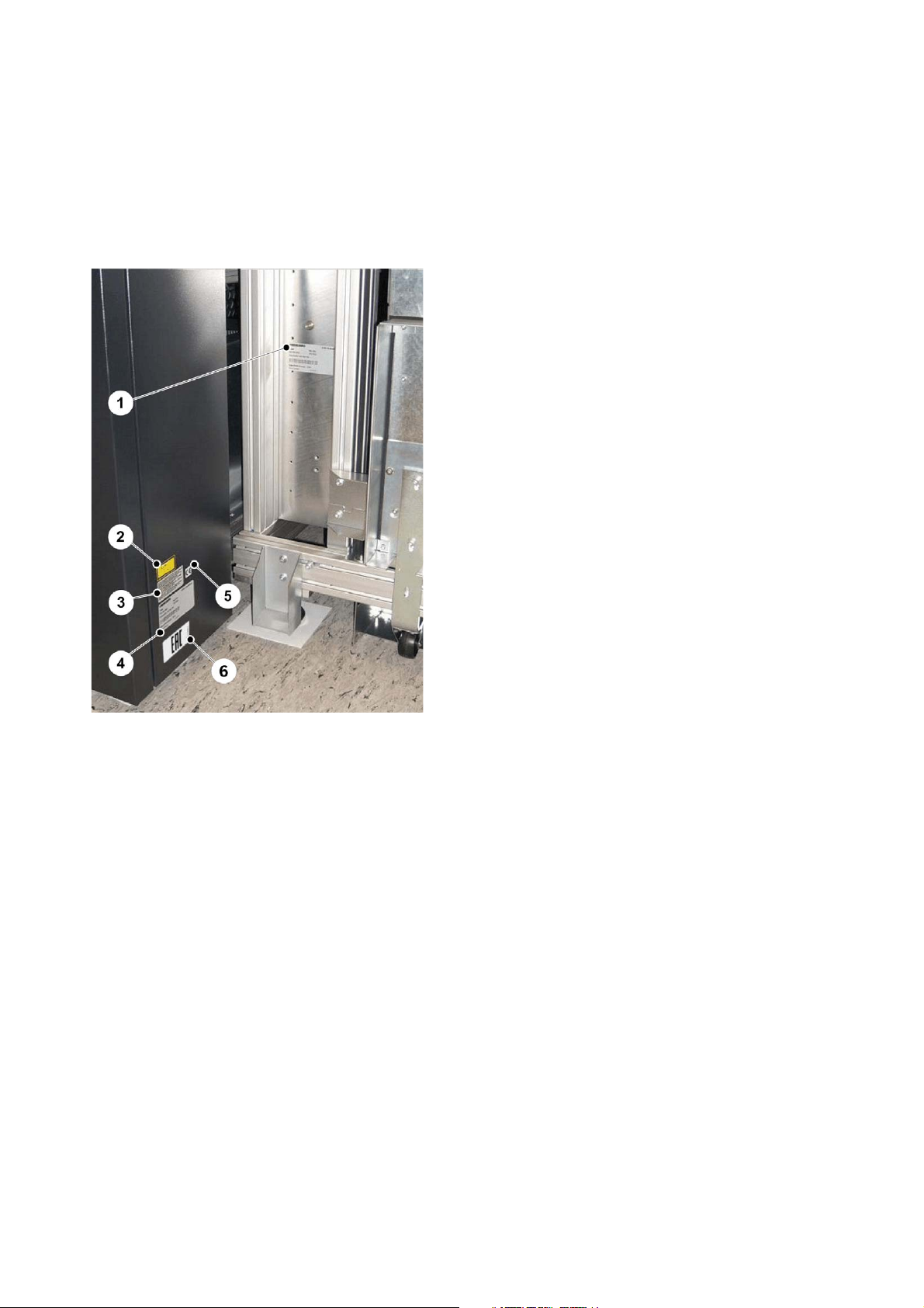
Overview of Labels
Mounting locations
Fig. 7/1: Type label of plate loader
Fig. 7/2: Laser Product Class 1
Fig. 7/3: Note on conformance (USA)
Fig. 7/4: Type label
Fig. 7/5: CE Mark of conformity (Europe)
Fig. 7/6: EAC label (Russia)
Fig. 7 Imaging unit with plate loader
20
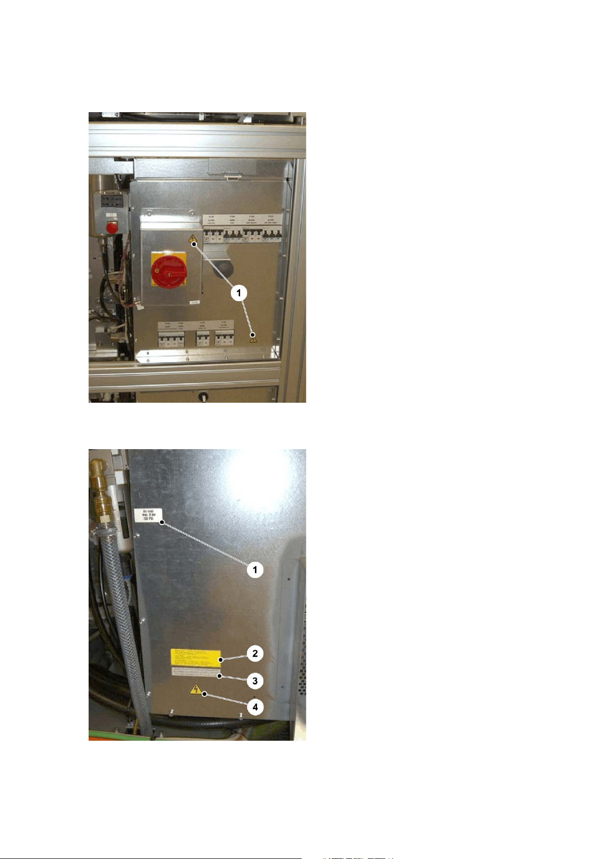
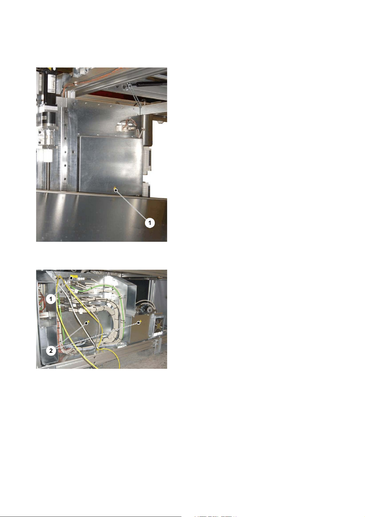
Fig. 8/1: Flash: Beware of high voltage
Safety
Fig. 8 Imaging unit, power connection and fuses
Fig. 9/1: Air Inlet
Fig. 9/2: High leakage current
Fig. 9/3: Heed installation instructions
Fig. 9/4: Flash: Beware of high voltage
Fig. 9 Imaging unit power supply box, outside
Suprasetter 145/162/190 – Installation 21
Safety
Fig. 10 Imaging unit power supply box, inside
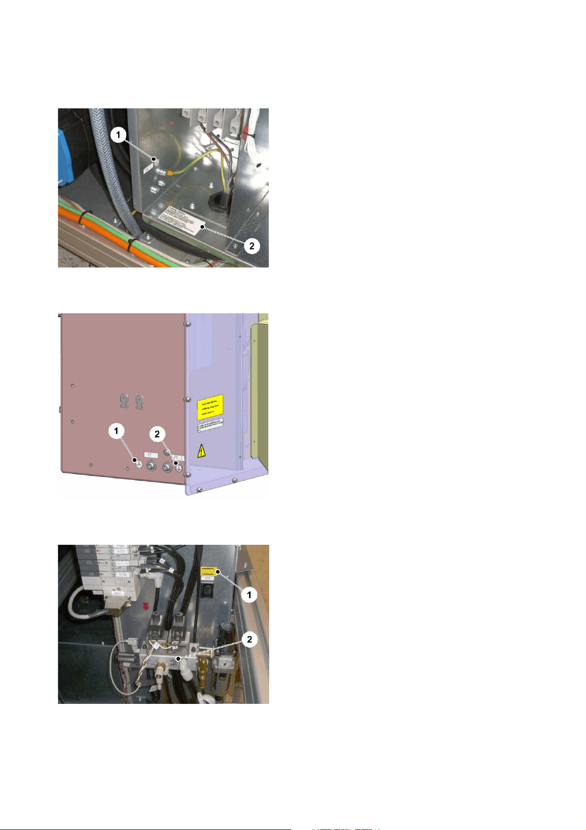
Fig. 10/1: Symbol for protective conductor terminal (PE)
Fig. 10/2: Note on additional PE cable
Fig. 11/1: Symbol for functional earthing (FE)
Fig. 11 Power supply box, on side
Fig. 11/2: Symbol for additional protective conductor terminal (PE)
Fig. 12/1: AC outlet: Supply voltage for cross conveyor
Fig. 12/2: Air outlet: Compressed air connector for
separator
Fig. 12 SuprasetterComp. air
22
Safety
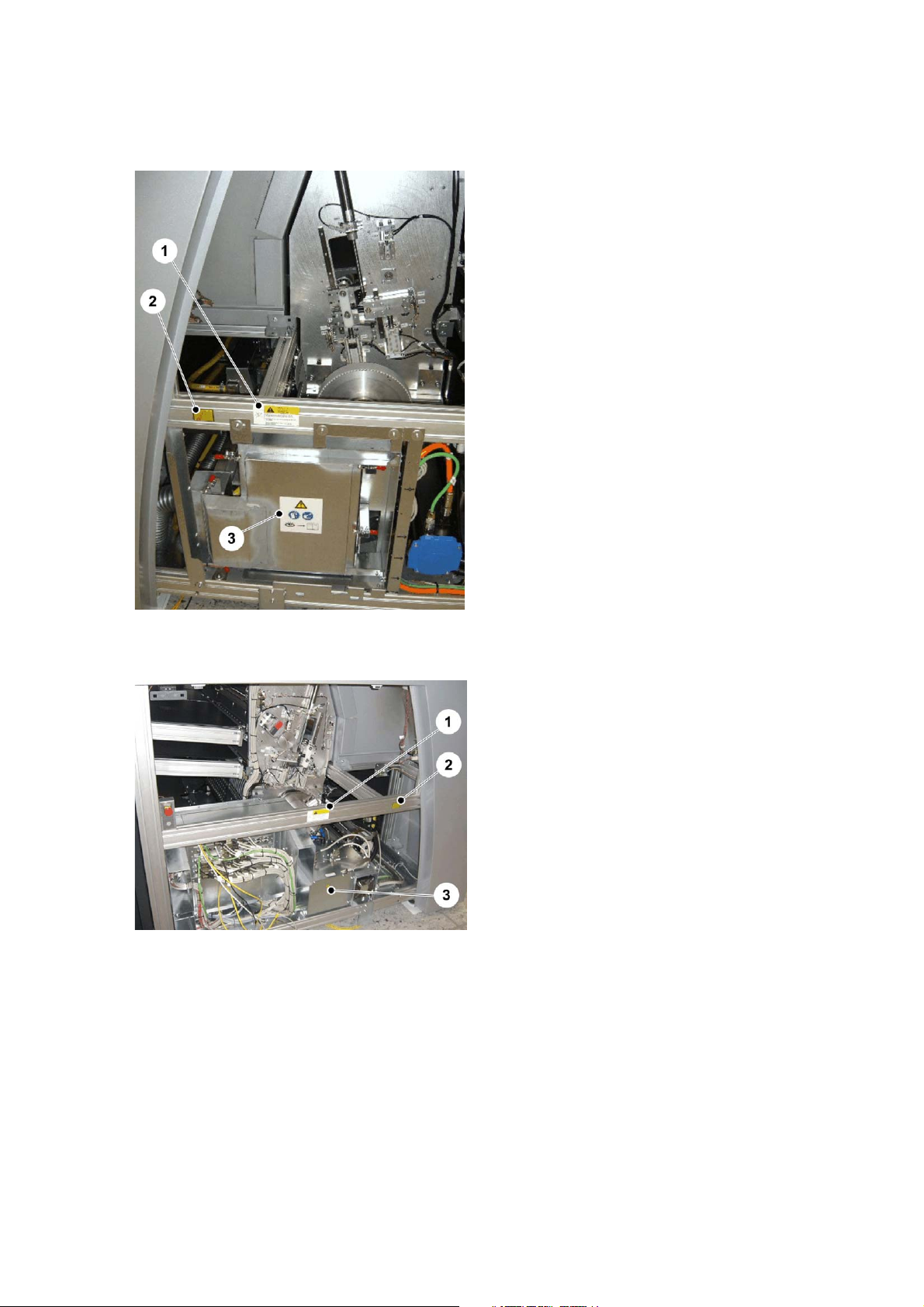
Fig. 13/1: Beware of moving parts
Fig. 13/2: Invisible Class 4 Laser Radiation
Fig. 13/3: Warning/information label on exhaust
(option)
Fig. 13 Imaging unit, right side
Fig. 14 Imaging unit, left side
Fig. 14/1: Beware of moving parts
Fig. 14/2: Invisible Class 4 Laser Radiation
Fig. 14/3: Flash: Beware of high voltage
Suprasetter 145/162/190 – Installation 23
Safety
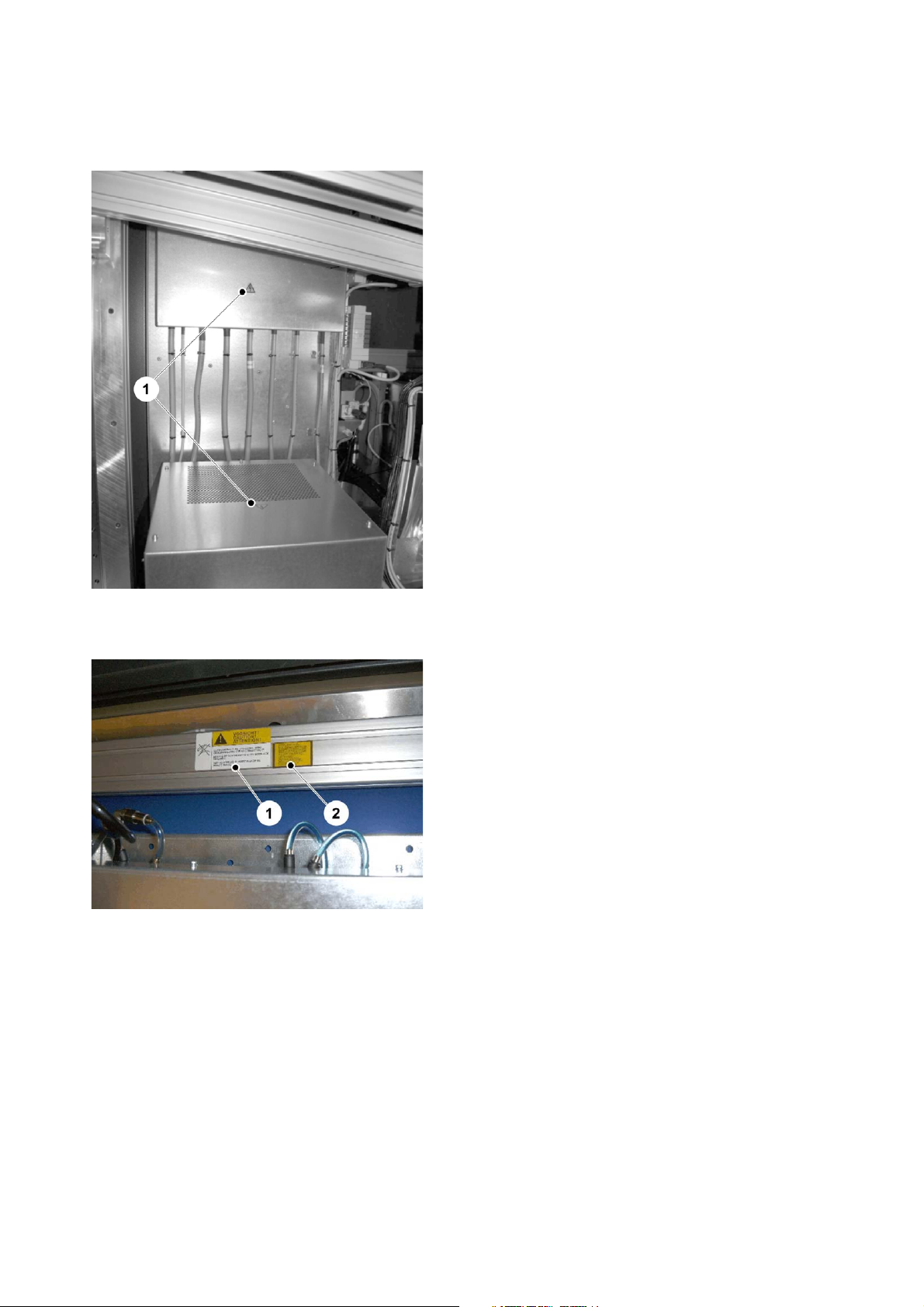
Fig. 15/1: Flash: Beware of high voltage
Fig. 15 Imaging unit, choke housing
Fig. 16 Imaging unit, strut in front of drum
Fig. 16/1: Beware of moving parts
Fig. 16/2: Invisible Class 4 Laser Radiation
24
Safety
Fig. 17/1: Beware of moving parts (on both sides
of the upper bracing on the double lift table in the
plate loader)
Fig. 17 Lift table of plate loader
Fig. 18 Imaging unit, laser carriage electronics
Fig. 18/1: Warning label "Connect data cable only
when machine is switched off" on the cover of the
electronics on the laser carriage.
Suprasetter 145/162/190 – Installation 25
Safety
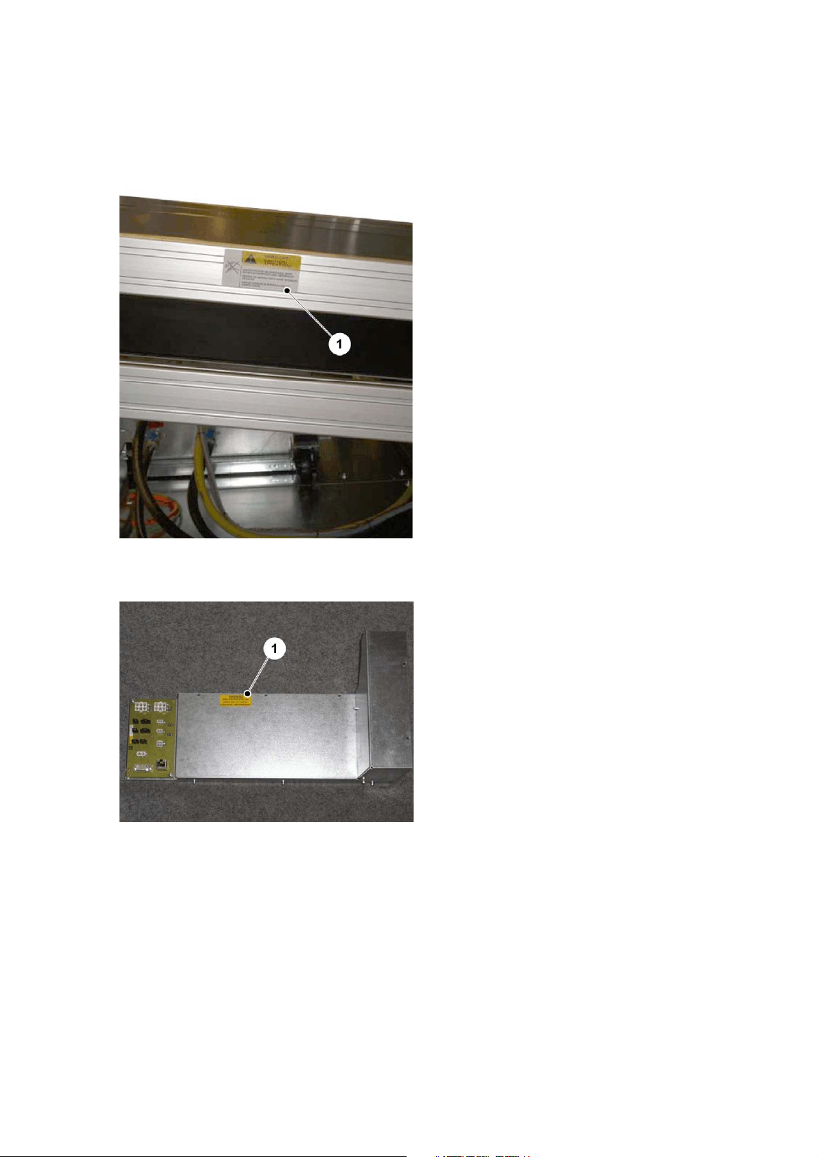
Fig. 19/1: Flash: Beware of high voltage
Fig. 19 Central unit, rear
Fig. 20 Electronics unit
Fig. 20/1: Warning label: Data cable
Fig. 20/2: Flash: Beware of high voltage
26
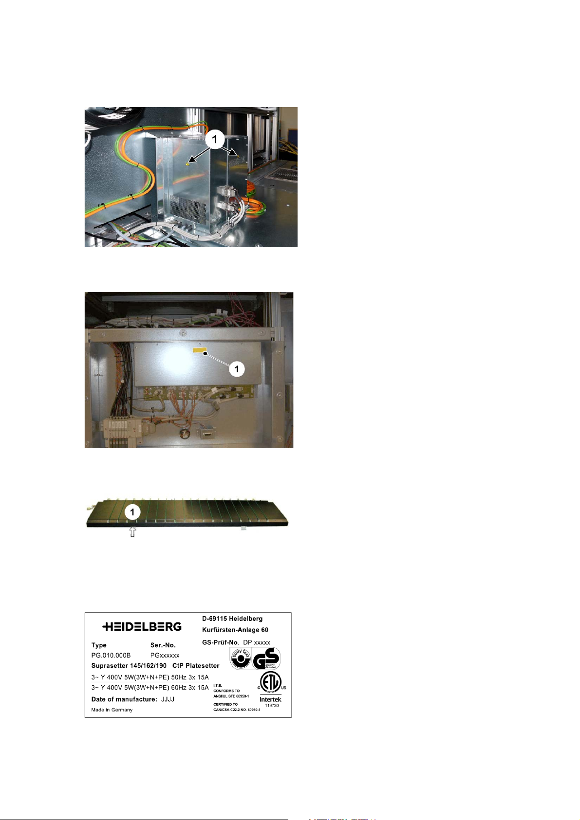
Fig. 21 Servo drive in plate loader
Safety
Fig. 21/1: Flash: Beware of high voltage
Fig. 22/1: Warning label: Data cable
Fig. 22 Electronics door of plate loader
Fig. 23 Input/output table (option)
Labels
Fig. 24 Type label Suprasetter 145/162/190
Fig. 23/1: Type label under the input/output table
Location:
Fig. 7/4: On the recorder outside
Fig. 7/1: Inside on the chassis of the plate loader
Suprasetter 145/162/190 – Installation 27
Safety
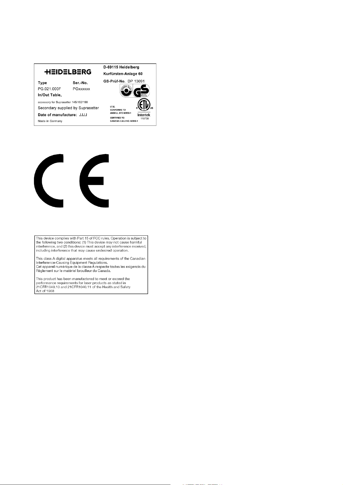
Fig. 25 Type label input/output table
Location:
Fig. 23/1: under the input/output table (option)
Location:
Fig. 7/5: On the Suprasetter outside:
Fig. 26 CE mark of conformity
Fig. 27 Note on conformance
FCC, CDRH note on conformance (USA)
Location: on the Suprasetter outside (Fig. 7/3)
28
 Loading...