

HEIDELBERG Suprasetter 74, Suprasetter 106 Operation

Suprasetter 74/105
Operation
Edition September 2005
Order No. PL.999.0005
ABC

ABC
I
Add
mprint/Company
ress
Copyright © 2005 Heidelberger
Druckmaschinen AG.
No part of this book may be reproduced without prior written permission.
Heidelberger Druckmaschinen AG
Dr.-Hell-Strasse
D-24107 Kiel
Phone +49 (4 31) 3 86-0
Fax +49 (4 31) 3 86-1380
http://www.heidelberg.com/
. . . . . . . . . . . . . . . . . . . . . . . . . . . . . . . . . . . . . . . . . . . . . . . . . . . . . . . . . . . . . . .
Heidelberg and the Heidelberg logo
are registered trademarks of Heidelberger Druckmaschinen AG.
®
PostScript
Systems Incorporated.
is a trademark of Adobe
Other company names, product
names and trademarks not expressly
mentioned in this manual are trademarks or registered trademarks of
the corresponding manufacturers
and fall within the regulations
regarding the protection of trademarks.
. . . . . . . . . . . . . . . . . . . . . . . . . . . . . . . . . . . . . . . . . . . . . . . . . . . . . . . . . . . . . . .
Important notice:
We are dedicated to improving and
enhancing our products. Consequently, the information in this
manual is subject to change without
notice.
Heidelberger Druckmaschinen AG
assumes no responsibility for information and description as far as
third-party products are concerned.
The information contained in this
manual about performance and
speed as well as technical data con-
cerning application of our products
is not legally binding as it does not
constitute a written contract of features.
If any problems occur with the product described in this manual, please
contact the agency which is responsible for you.
Order No. PL.999.0005
Edition September 2005
Printed in Germany.
. . . . . . . . . . . . . . . . . . . . . . . . . . . . . . . . . . . . . . . . . . . . . . . . . . . . . . . . . . . . . . .

ABC Table of Contents
Table of Contents
Table of Contents
Before You Start ...
Technical Remarks on Safety . . . . . . . . . . . . . . . . . . . . . VII
Correct Use . . . . . . . . . . . . . . . . . . . . . . . . . . . . . . . . . . . . . VII
General . . . . . . . . . . . . . . . . . . . . . . . . . . . . . . . . . . . . . . . . VII
Power Switch with Emergency Stop Function . . . . . . . . . . . VII
Emergency Switch . . . . . . . . . . . . . . . . . . . . . . . . . . . . . . VIII
On/Off button . . . . . . . . . . . . . . . . . . . . . . . . . . . . . . . . . . VIII
Laser Safety . . . . . . . . . . . . . . . . . . . . . . . . . . . . . . . . . . . . . IX
Service and Maintenance . . . . . . . . . . . . . . . . . . . . . . . . . . . IX
Safety Loop . . . . . . . . . . . . . . . . . . . . . . . . . . . . . . . . . . . . . . X
ESD Protective Measures for Prepress Systems and Users . X
Basics . . . . . . . . . . . . . . . . . . . . . . . . . . . . . . . . . . . . . . . . X
Formation . . . . . . . . . . . . . . . . . . . . . . . . . . . . . . . . . . . . . XI
Practical Tips . . . . . . . . . . . . . . . . . . . . . . . . . . . . . . . . . . XI
Standards/Sources . . . . . . . . . . . . . . . . . . . . . . . . . . . . . XII
About This Documentation . . . . . . . . . . . . . . . . . . . . . . . XII
Prerequisites . . . . . . . . . . . . . . . . . . . . . . . . . . . . . . . . . . . XIII
Further Documentation . . . . . . . . . . . . . . . . . . . . . . . . . . XIII
Symbols and Styles . . . . . . . . . . . . . . . . . . . . . . . . . . . . . XIII
Important Information . . . . . . . . . . . . . . . . . . . . . . . . . . . . XIV
Any Comments on this Documentation? . . . . . . . . . . . . XIV
HEIDELBERG online . . . . . . . . . . . . . . . . . . . . . . . . . . . . . XV
1Introduction
Description of the Unit and its Functions . . . . . . . . . . . 1-1
Status LEDs . . . . . . . . . . . . . . . . . . . . . . . . . . . . . . . . . . . . 1-2
On/Off button . . . . . . . . . . . . . . . . . . . . . . . . . . . . . . . . . . . 1-4
Power switch . . . . . . . . . . . . . . . . . . . . . . . . . . . . . . . . . . . 1-4
Punch Systems . . . . . . . . . . . . . . . . . . . . . . . . . . . . . . . . . . 1-5
2 Notes on Installation
Installing the unit . . . . . . . . . . . . . . . . . . . . . . . . . . . . . . . 2-1
Connecting the Device . . . . . . . . . . . . . . . . . . . . . . . . . . . 2-1
Suprasetter 74/105 – Operation III

Table of Contents ABC
Automatic Cutouts . . . . . . . . . . . . . . . . . . . . . . . . . . . . . . 2-3
Software Installation (Container Version) . . . . . . . . . . 2-4
Updating the Software for the Recorder . . . . . . . . . . . . . . 2-6
Saving a Backup of the Recorder Configuration . . . . . . 2-7
Selecting the User Interface Language . . . . . . . . . . . . 2-8
3Operation
Switching on the Device . . . . . . . . . . . . . . . . . . . . . . . . . 3-1
Manual Startup . . . . . . . . . . . . . . . . . . . . . . . . . . . . . . . . . . 3-1
Automatic Startup . . . . . . . . . . . . . . . . . . . . . . . . . . . . . . . . 3-2
Switching Off the Device . . . . . . . . . . . . . . . . . . . . . . . . . 3-3
Shutdown using the User Interface on the Workstation . . . 3-3
Shutdown with the On/Off Button on the Device . . . . . . . . 3-3
Material Handling . . . . . . . . . . . . . . . . . . . . . . . . . . . . . . 3-5
Material storage . . . . . . . . . . . . . . . . . . . . . . . . . . . . . . . . 3-5
Manual Loading of a Printing Plate . . . . . . . . . . . . . . . 3-6
Removing a Printing Plate . . . . . . . . . . . . . . . . . . . . . . . 3-9
Troubleshooting . . . . . . . . . . . . . . . . . . . . . . . . . . . . . . . 3-10
Switching on an Automatic Cutout . . . . . . . . . . . . . . . . . . 3-11
4 Service and Maintenance
General . . . . . . . . . . . . . . . . . . . . . . . . . . . . . . . . . . . . . . . 4-1
Cleaning the unit . . . . . . . . . . . . . . . . . . . . . . . . . . . . . . . 4-1
Cleaning the Cleaning Rollers on the Imaging Drum and
Insertion Table . . . . . . . . . . . . . . . . . . . . . . . . . . . . . . . . . 4-2
Removing the Punch Waste . . . . . . . . . . . . . . . . . . . . . . 4-8
Changing the air filter . . . . . . . . . . . . . . . . . . . . . . . . . . 4-13
5 Technical Data
Protection and Safety Requirements . . . . . . . . . . . . . . . 5-3
Standards . . . . . . . . . . . . . . . . . . . . . . . . . . . . . . . . . . . . . . 5-3
General . . . . . . . . . . . . . . . . . . . . . . . . . . . . . . . . . . . . . . . . 5-3
Laser safety . . . . . . . . . . . . . . . . . . . . . . . . . . . . . . . . . . . . 5-3
Mechanical Safety . . . . . . . . . . . . . . . . . . . . . . . . . . . . . . 5-4
Electrical Safety . . . . . . . . . . . . . . . . . . . . . . . . . . . . . . . . 5-4
IV Edition September 2005

ABC Table of Contents
Electromagnetic Compatibility (EMC) . . . . . . . . . . . . . . . . . 5-4
Interference Emission (Stray Radiation and Interference
Voltage) . . . . . . . . . . . . . . . . . . . . . . . . . . . . . . . . . . . . . . . 5-4
Interference Immunity . . . . . . . . . . . . . . . . . . . . . . . . . . . . 5-5
Radio Interference Suppression . . . . . . . . . . . . . . . . . . . . . 5-5
Approvals and Conformity . . . . . . . . . . . . . . . . . . . . . . . . . 5-5
Disposal of the unit . . . . . . . . . . . . . . . . . . . . . . . . . . . . 5-6
General Dimensions . . . . . . . . . . . . . . . . . . . . . . . . . . . . . 5-6
Harmful Substances . . . . . . . . . . . . . . . . . . . . . . . . . . . . . 5-6
Disposal of Glysantin . . . . . . . . . . . . . . . . . . . . . . . . . . 5-8
Recyclable Materials . . . . . . . . . . . . . . . . . . . . . . . . . . . . 5-8
Dismantling . . . . . . . . . . . . . . . . . . . . . . . . . . . . . . . . . . . 5-10
Disposal Instructions for Chiller P107-13188 . . . . . . . . . . . 5-20
Labels on the Suprasetter 74/105 . . . . . . . . . . . . . . . . 5-21
6Quality Assurance
Quality Assurance . . . . . . . . . . . . . . . . . . . . . . . . . . . . . . 6-1
Central Call Desk . . . . . . . . . . . . . . . . . . . . . . . . . . . . . . . . 6-1
Problem Report for Customers and Service Technicians . . 6-1
Index
Suprasetter 74/105 – Operation V


ABC Before You Start ...
Before You Start ...
Technical Remarks on Safety
This device complies with the safety regulations of
the standards and specifications listed in the "Technical Data" chapter.
Correct Use
The Suprasetter 74/105 is a laser imagesetter for imaging offset printing plates and may only be used for
this purpose as described in the customer documentation.
Do not place any objects or liquids on the device.
Ventilation outlets must be kept clear at all times.
General
The Suprasetter 74/105 is to be installed by authorized
service personnel only. The ambient conditions must
be observed.
Warning: Unauthorized opening of of any parts of the
casing not specifically referred to in the operating
3
manual and inexpert repairs can lead to considerable
danger for the user.
Service work
personnel trained for this purpose. The respective
accident prevention regulations must be observed at
all times.
Non-observance of accident prevention regulations
can lead to the loss of accident insurance cover.
Power Switch with Emergency Stop Function
The Suprasetter 74/105 is fully cut off from the power
supply by the power switch (red rotary switch).
Suprasetter 74/105 – Operation VII
may only be performed by authorized

Before You Start ... ABC
The power switch (red rotary switch) triggers a fourpole cut-off of the Suprasetter 74/105 and the SCL 74/
102 from the power supply. In an emergency, this
power switch is used as an emergency stop switch for
the Suprasetter 74/105 and the SCL 74/102.
Emergency Switch
All mechanical motions in the device are stopped and
the invisible
laser beam is switched off when the
emergency switch is used. Use this switch in cases of
emergency. It is located behind the upper left side
panel.
On/Off button
The Suprasetter 74/105 is only de-energized by the On/
Off button.
All connectors and outlets of the service line must be
easily accessible at all times because you must fully
disconnect the device from the power supply, for
example, in hazardous situations, by using the power
switch or pulling out the power connector.
When connecting or disconnecting the power cable,
only ever hold the cable at the plug and make sure
that your hands are not wet. A damaged power cable
can cause leakage currents and electric shocks. Protect the power cable from being damaged. Never place
any heavy objects upon it and do not allow it to get
jammed.
VIII Edition September 2005

ABC Before You Start ...
Laser Safety
The Laser Imagesetter is a Class 1 laser product.
Service and Maintenance
3
This means that the invisible
duced in the unit is shielded by means of protective
covers.
If used as directed, the user is never exposed to danger from the laser beam.
The laser systems used in the Suprasetter 74/105 are
Class 4 products (> 500 mW).
Companies which are servicing the device in Germany must appoint a laser safety officer in accordance with the Accident Prevention Regulations (BGV
B2) from the Professional Trade Association.
Servicing may only be carried out by Heidelberg
personnel who have been trained by appropriate
laser protection officers for this purpose.
Service work may only be carried out by persons
authorized by Heidelberg.
The respective accident prevention regulations must
be observed at all times.
Warning: Never remove covers or any other parts of
the casing except for the work described in the "Service and Maintenance" and "Troubleshooting" chapters. When doing so, keep to the stipulated sequence
of operations.
laser radiation pro-
If you do not, the invisible
ries to eyes and skin and/or you may suffer a fatal electric shock.
Suprasetter 74/105 – Operation IX
laser beam may cause inju-

Before You Start ... ABC
Warning: You may be exposed to dangerous radiation
Safety Loop
3
by the invisible
adjustment equipment other than those mentioned
in this documentation or if you follow other working
procedures.
When carrying out work as described in the customer
documentation, the user must always adhere to the
operating process stipulated. Protection from the
invisible
loops.
The use of laser protection glasses is not in the plans
as correct operation eliminates the need for these.
For your safety, the output device is equipped with a
safety loop. If the safety loop is interrupted, e.g. by
removing the insertion table, all mechanical motions
are stopped and the invisible
off in the exposure head.
laser beam if you use operating or
laser beam is ensured by covers or safety
laser beam is switched
This safety system must never be bridged as otherwise
you are in danger of being injured by the invisible
laser beam, of being crushed by the optics carriage or
being fatally injured by an electric shock.
ESD Protective Measures for Prepress Systems and Users
Basics
Devices from Heidelberger Druckmaschinen AG are
resistant to electrostatic discharges (within the limits
of EN 55024:2001).
In order to protect devices and users from being
unnecessarily exposed to such discharges, we have
listed a few tips below that will help reduce the frequency and intensity of the discharges.
X Edition September 2005

ABC Before You Start ...
Formation
In a prepress environment, this physical phenomenon occurs most frequently as a result of triboelectricity. In such cases, electrostatic charges are generated when bodies that have close contact are
separated.
Examples:
0
Walking across non-conductive (insulating) flooring (e.g. synthetic floor covering)
0
Removing the slip sheet from the plate
0
Getting up off a seat
The intensity of these charges is determined basically
by the following parameters:
0
Humidity
0
Roughness of the material surface
0
Pressure/space when in contact
0
Conductivity of the materials
Practical Tips
The following practical tips are to help reduce the
number and intensity of electrostatic discharges
when handling the devices:
0
Install the devices in rooms that have conductive
floor covering.
0
Resistance to ground < 1x10⁹ ohms (IEC/EN 61340-
-5). Synthetic carpeting does not comply with this
requirement in the majority of cases. Pure concrete flooring generally has a low volume resistance. If you have non-conductive floor covering,
the use of ESD mats placed on the operator side of
the devices is recommended. These mats can be
Suprasetter 74/105 – Operation XI

Before You Start ... ABC
obtained from suppliers. However, in such a case,
existing charges are only slowly reduced depending on the shoes that the personnel wear. For personal safety, the resistance of floor to ground
should not fall below 10
0
The humidity at the installation site should not
5
ohms.
fall below 45% relative humidity. High air humidity is a decisive factor in preventing the formation
of electrostatic charges. For example, a relative
humidity of 10 - 20% will produce 35,000 V when
crossing a carpet. This value drops to 1,500 V with
a relative air humidity of 65 - 90%.
0
Clothing where cotton material is >50%.
0
Conductive seating.
0
ESD shoes that can be obtained from suppliers and
are used on conductive flooring help further to
reduce charges when walking across floor coverings.
Standards/Sources
More details on this subject can be found in the following source:
0
IEC / EN 61340-5 (Protection of electronic devices
from electrostatic phenomena - General Requirements)
About This Documentation
This documentation is intended as a reference work
for the operator during training courses and in operation.
Note: The documentation must be kept safely for
future use right up to the disposal of the device.
2
XII Edition September 2005

ABC Before You Start ...
Prerequisites
The user, having attended a training course, should
be familiar with the Suprasetter 74/105.
Further Documentation
You will find additional information in the following
documentation:
0
MetaDimension - User's Guide/Workflow
0
Prinect Printready System - User's Guide/Workflow
Symbols and Styles
The following typographical conventions are used in
this manual:
0
Cross-references to other chapters and sections are
underlined
Example:
See section
0
Quotes are used to indicate menus, folders, names
of functions, hardware conditions, switch settings, system messages, etc.
and, on the monitor, blue.
Symbols and Styles.
Example:
Set the switch to "off".
0
Menus, functions and submenus are separated
from one another by a ">".
Example:
Select "File > Open..."
0
A plus sign is used to indicate that several keys
have to be pressed at the same time.
Example:
Press Alt+A.
Suprasetter 74/105 – Operation XIII

Before You Start ... ABC
0
„V" in front of a word indicates that it is explained
in the Glossary.
Important Information
Important information in the text is marked by symbols which indicate the following:
Warning:
Contains information that must be taken into consid-
3
1
eration to protect the user from injury.
Attention: Contains information that must be taken
into consideration to prevent damage to hardware or
software.
Note: Contains important general or supplementary
information about a specific topic.
2
Prerequisites: This text contains requirements which
must be fulfilled before the steps which follow can be
5
performed.
Any Comments on this Documentation?
We would like to know if our documentation meets
your requirements.
0
Can you find the information you are looking for?
(and quickly enough?)
0
Does this documentation help you to solve any
problems which might occur?
0
Where do you think there is room for improvement? ...
If you would like to make some comments on the documentation, please feel free to send these to us at the
following e-mail address:
XIV Edition September 2005

ABC Before You Start ...
documentation.prepress@heidelberg.com
It would help us if you could write your comments in
English or German.
Important!
This e-mail address should only be used to send us
comments, corrections, criticism and suggestions
about the actual documentation. If you have comments which you would like to make on the improvement or enhancement of our products, please forward these to us using the "Problem Report for
Customers and Service Technicians".
To order documentation, please contact the Heidelberg agency which is responsible for you.
HEIDELBERG online
Do you have questions concerning our products?
Do you want to improve your workflows?
Pay us a visit at our Internet home page. You will find
us at:
http://www.heidelberg.com/
Suprasetter 74/105 – Operation XV

ABC Introduction
1 Introduction
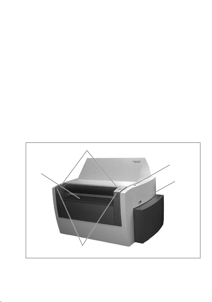
Description of the Unit and its Functions
The Suprasetter 74/105 is a high-speed, PostScript™compatible, computer-to-plate imaging device.
It images thermal printing plates in daylight operation.
The Suprasetter 74/105 receives screened data from
the RIP for imaging onto printing plates. The printing
plates are placed manually on the insertion table or
loaded by the Single Cassette Loader. The Suprasetter
74/105 automatically loads the printing plate onto
the drum, images it, punches it (option) and then
transports the imaged plate back to the insertion
table or, if an online processor is connected, directly
to the processor.
Load buttons
On/Off button
Insertion table
Power switch
Status LEDs
Suprasetter 74/105 – Operation 1–1
Introduction ABC
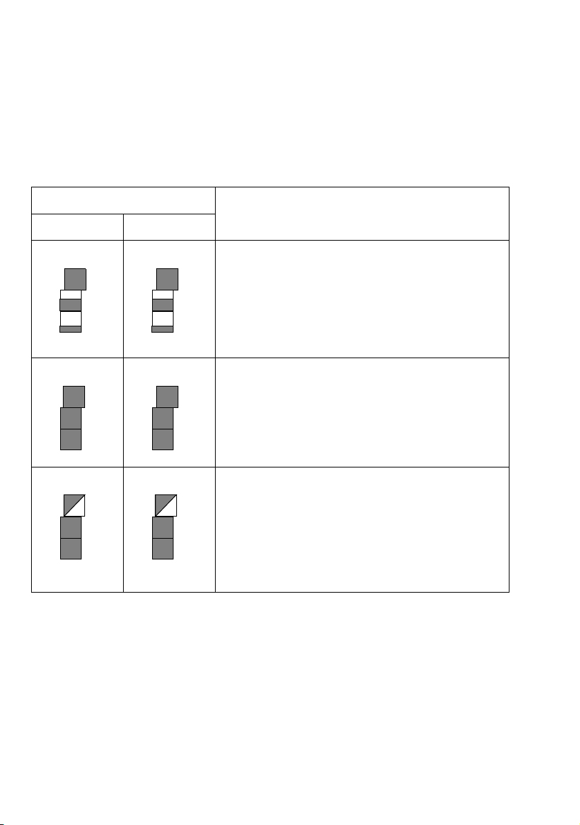
Status LEDs
The following actions of the Suprasetter 74/105 are
indicated by the status LEDs:
Position of the status LEDs
Actionleft right
Startup:
The device starts the software and initializes
the hardware.
The status LEDS are like level indicators filling
up from bottom to top, running parallel on
both sides, until normal operation is reached.
Standby:
The device is ready to image a plate but is not
busy imaging at that moment.
All LEDs light up.
Normal operation:
The device is presently imaging a plate or otherwise busy, for example, it is unloading a plate to
the online processor or loading a plate from the
Autoloader.
The top LEDs flash synchronously.
1–2 Edition September 2005
ABC Introduction
Error:
An error occurred that must be eliminated by
the user.
The LEDs on each level flash, alternating
between left and right. A beep also indicates
the error status.
The user must go to the GUI of the device to
learn more details about the error.
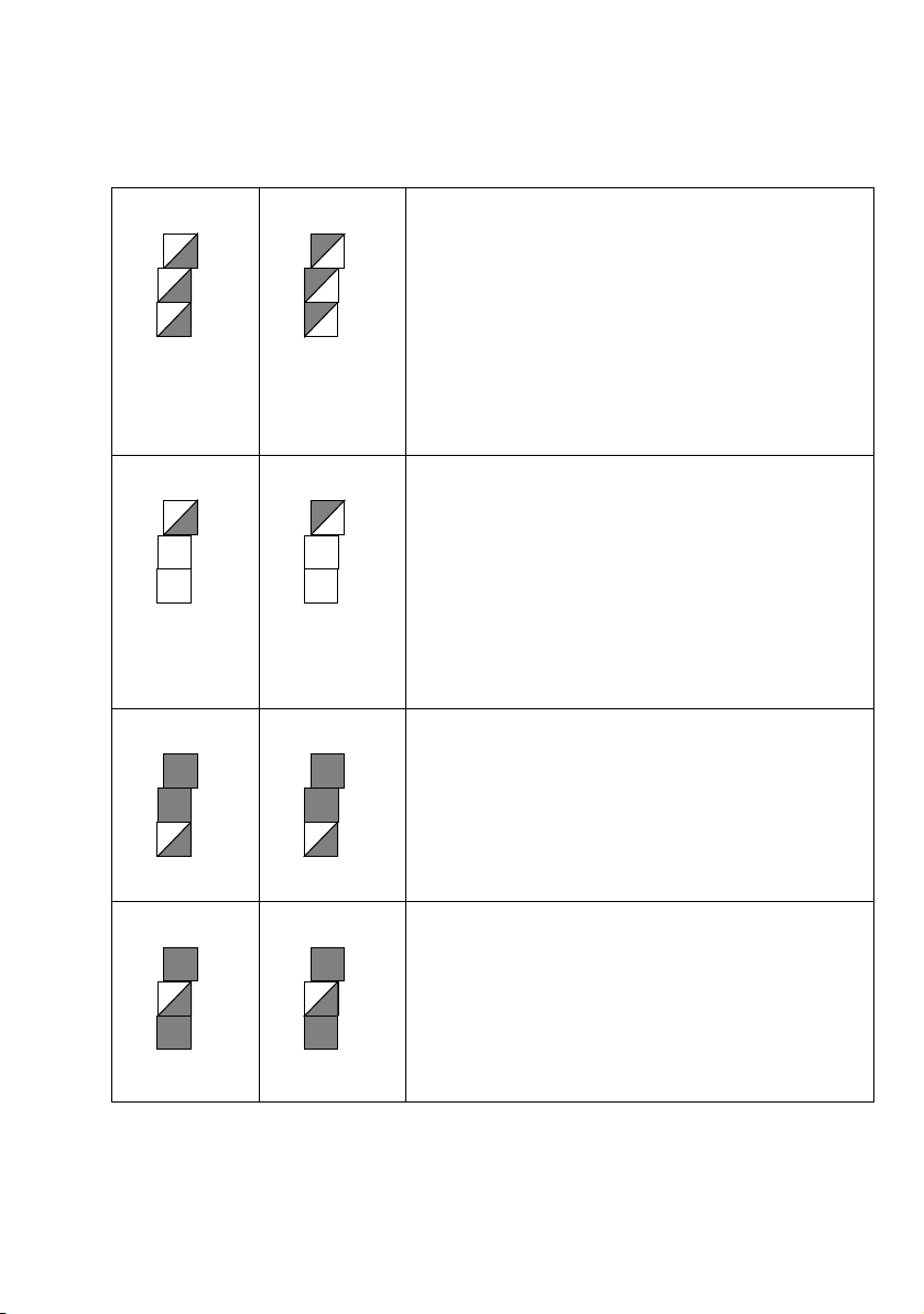
Waiting:
The device is waiting for something within it
(e.g. until the operating temperature is
reached) or is waiting for a connected device
(online processor or the cassette loader).
The top LEDs flash alternately. A brief beep is
also heard if an operator intervention is
required.
Waiting for a plate:
The user is prompted to insert the required
plate.
The bottom LEDs flash synchronously. A brief
beep is also heard.
Plate ready to be removed:
Output of an imaged plate is announced
approx. 3 seconds before by a beep. In addition,
the middle LEDs flash synchronously.
If the plate is output a brief beep is heard again,
indicating that the plate can be removed.
Suprasetter 74/105 – Operation 1–3

Introduction ABC
On/Off button
The On/Off button allows you to:
0
switch on the Suprasetter 74/105, see
section
0
switch off the Suprasetter 74/105, see
section
0
switch off the beep that sounds, for example, after
Switching on the Device, page 3–1.
Switching Off the Device, page 3–3.
a malfunction occurs.
Power switch
You can disconnect the device fully from the power
supply with the power switch, for example, for maintenance work. You can switch on the device only
when the power switch is set to 'I'.
1–4 Edition September 2005
ABC Introduction
Punch Systems
As an option, you can equip your Suprasetter 74/105
with different punch systems.
The punches are located within the device. They
punch the printing plate after exposure before finally
unloading the plate.
Max. number of
Max. number of
Device
punch systems
Suprasetter 74 3 6
Suprasetter 105 4 8
The following punch gaps are possible:
0
220 mm gap for QM 46
0
425 mm gap for GTO and SM 52/74
0
550 mm gap for Komori
0
780 mm gap for SM 102
(Suprasetter 105 only)
0
830 mm gap for Komori 44
(Suprasetter 105 only)
punches per
system
Suprasetter 74/105 – Operation 1– 5


ABC Notes on Installation
2 Notes on Installation
Installing the unit
The Suprasetter 74/105 may only be installed by
authorized service personnel. The ambient conditions must be observed.
Because the installation site must have clean conditions, the Suprasetter 74/105 may not be operated in
sites where paper is being printed or paper finishing
devices are running.
The floor at the installation site must be even and
firm.
Make sure that the device is installed at a sufficient
distance from walls and other objects to ensure adequate ventilation and proper servicing.
For minimum distances, see the drawings at the end
of the Kapitel
The device should not be installed near air-conditioning equipment and must be protected from humidity
and direct sunlight.
Technical Data.
Note: The initial installation is performed by service
personnel. This includes lifting the device off the pal-
2
let and removing the transport safeguards.
Connecting the Device
Warning: The connecting cables may only be connected by authorized qualified personnel and with
3
1
Suprasetter 74/105 – Operation 2–1
the power off. Connect the connecting cables before
you connect the power cables of the front-end device
and of the Suprasetter 74/105. Make sure that the
cables and hoses are routed so that you do not trip
over them.
Attention: Only use shielded cables for compliance
with radio interference suppression regulations.

Notes on Installation ABC
Connection to the power supply is with a 5-pin connector or is permanent. The power cable must be
designed for connection to 200 - 240 V AC. The respective national regulations must be observed when connecting the device using power cables not provided
by Heidelberg or when using adapted connectors.
The unit may only be operated if a grounded connector is installed.
In the USA and Canada, power supply cables must at
least comply with type SJT.
Warning: Connectors and outlets of the service line
must be easily accessible as the device has to be com-
3
3
pletely disconnected from the power supply by using
the power switch or by pulling out the power connector, for example, in hazardous situations. The inhouse installation socket must be placed at least 60
cm above the ground.
Warning: The power switch triggers a four-pole cut-off
of the device from the power supply and the device is
then dead, except for the power cable connection up
to this switch.
Connection to various supply circuits is implemented
by different distributor connectors in the power pack
of the Suprasetter 74/105. Connection of the device to
the power supply may only be performed by authorized qualified personnel.
2–2 Edition September 2005
ABC Notes on Installation
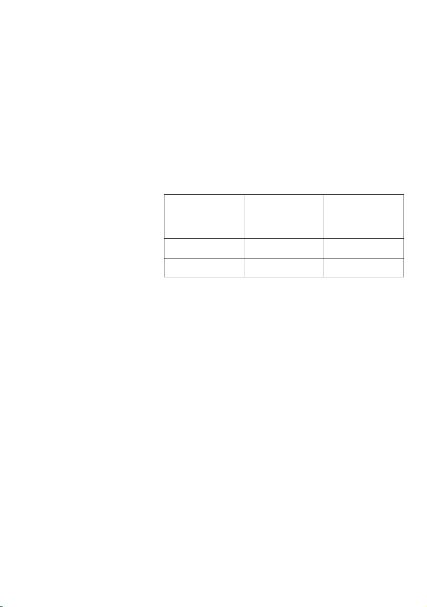
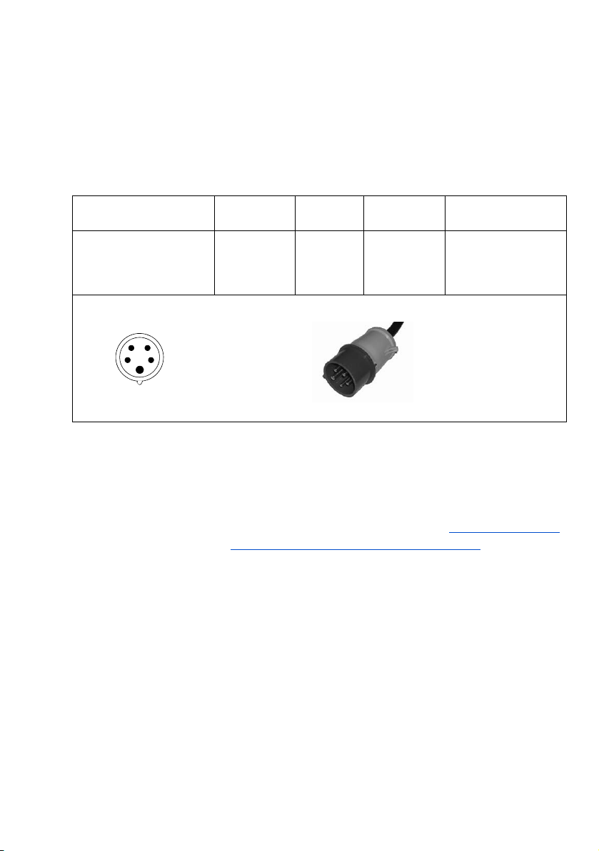
Notes on connecting the power cable:
For a 200 V - 240 V AC connection, the following
2
power cable must be used for a permanent connection or for the connector type shown below.
Type of Connector Country
Automatic Cutouts
Europe
250V / 16A
USA
240V / 32A
Line
IEC 309
Type B (CEE)
Mains
voltage
200 - 240 V IEC 83 <HAR> H05VV-F
Regulations Type of Cable
2
5 x 2.5 mm
SJT/VW1
only for USA/Canada:
length max. 4.5 m
or AWG12/
The automatic cutouts are located behind the right
side panel. When an automatic cutout is triggered,
please proceed as described in the Abschnitt
Switching on an Automatic Cutout, Seite 3–11. Repairs
should only be carried out by service personnel.
Suprasetter 74/105 – Operation 2– 3

Notes on Installation ABC
Software Installation (Container Version)
Requirements:
0
The Suprasetter 74/105 as well as the workstation
are switched on and ready for operation.
0
All Windows applications were run down.
0
Attention: A backup of the recorder configuration
is saved, see the Abschnitt
1
Recorder Configuration, Seite 2–7.
Operation:
1. Insert the Suprasetter 74/105 installation CD into the
CD-ROM drive.
With Autorun being activated the setup starts automatically.
2. If Autorun is disabled, you can start the setup by double-clicking "Setup.exe". The "CTP User Interface
Setup" window appears.
3. Click "Next". The "Choose Destination Location" window displays.
Saving a Backup of the
4. Select the appropriate path by clicking the "Browse"
button. You can also use the suggested path.
5. Click "Next". The "Select Program Folder" window
appears.
6. Choose one of the folders from the folder list, enter a
new folder name or use the already suggested folder.
7. Click "Next", the "Select Com Port" window displays.
8. In the "Select Com Port" window, select the Com port
the Suprasetter 74/105 is connected to.
9. Click "Next". The "Start Copying Files" window displays.
2–4 Edition September 2005

ABC Notes on Installation
10. Click "Next". The installation procedure is executed.
You will see the "Install Shield Wizard Complete" window at the end of the installation procedure.
11. Click "Finish". This completes installation.
12. To start the Suprasetter 74/105 user interface, select
"Start > Programs > Heidelberg > CTP User Interface"
or use the previously set path.
Suprasetter 74/105 – Operation 2– 5

Notes on Installation ABC
Updating the Software for the Recorder
After having installed the Container version on the
workstation, you need to update the software for the
recorder.
Requirements:
0
The Suprasetter 74/105 as well as the workstation
are switched on and ready for operation.
0
The Suprasetter 74/105 GUI was started.
Operation:
1. Click the "Change to Administration" button (wrench
icon).
2. Select "Software" in the vertical menu bar.
3. Select the "Software Update" tab.
4. Select the currently installed Container version from
the "Container Selection" list.
5. Click "Apply". The software update is started after the
user's acceptance of the confirmation request.
Attention: The update lasts approx. 30 minutes. You
may not switch off the recorder while the update is
1
2–6 Edition September 2005
running.
6. Confirm the end-of-update message with "OK".
 Loading...