

Page 1

SL-OCT
Slitlamp- OCT
Installation Instructions
Version 001, February 2009
© Heidelberg Engineering GmbH 2009
Art. No 18107
QM-Nr. 97 201-001
Page 2

SL-OCT Installation Manual
Art. No.: 18107 Page 2 of 42
Corporate Headquarters
Heidelberg Engineering GmbH • Tiergartenstr. 15 • 69121 Heidelberg • Germany
Phone +49 6221 6463-0 • Fax +49 6221 646362 • www.HeidelbergEngineering.de
US Main Office
Heidelberg Engineering, Inc. • 1499 Poinsettia Avenue, Suite 160 • Vista, CA 92081
Phone 760 598-3770 • Fax 760 598-3060 • www.HeidelbergEngineering.com
US Service Center
Heidelberg Engineering, Inc. • 410 Harris Road • Smithfield, RI 02917
Phone 401 349-0500 • Fax 401 349-0504 • www.HeidelbergEngineering.com
Page 3

SL-OCT Installation Manual
Art. No.: 18107 Page 3 of 42
Contents
1 INTRODUCTION 4
2 SCOPE 6
3 TOOLS 7
4 UNPACKING THE SYSTEM 8
4.1 Lift table 8
4.2 OCT-box 8
4.3 Slit lamp 8
5 INSTALLATION 9
5.1 Lift table 9
5.2 Optional printer table 16
5.3 OCT-box 19
5.4 Slit lamp 25
5.5 Electrical and fiber connections to the slit lamp 26
5.6 Electrical connections to the OCT-box 28
5.7 AC connections 29
5.8 Cleaning 30
6 TEST MEASUREMENT 31
7 DISASSEMBLY OF A SL-OCT UNIT 33
8 APPENDIX A: TROUBLESHOOTING 35
9 APPENDIX B: LIST OF SCREWS 37
10 APPENDIX C: PACKING LISTS 38
10.1 Lift table 38
10.2 OCT-box 39
10.3 Slit lamp 40
10.4 Optional printer table 42
Page 4
SL-OCT Installation Manual
Art. No.: 18107 Page 4 of 42
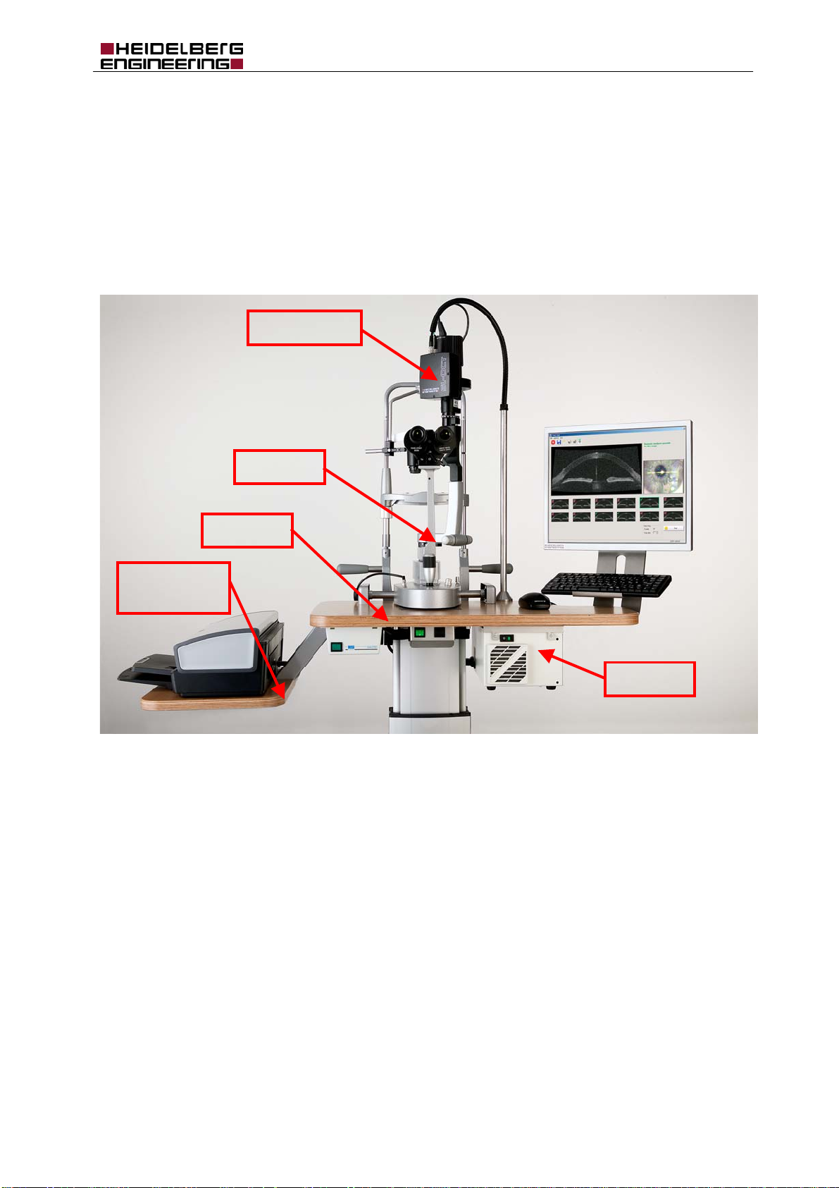
1 Introduction
The SL-OCT is a tomographic device for the viewing and axial, cross sectional imaging of anterior ocular
structures. It is used for the in vivo imaging and measurement of the anterior segment structures of the
eye.
This document describes the installation of the SL-OCT device. It also contains important safety
information.
NOTE: To ensure the overall safety of the system, the SL-OCT must be installed by certified staff
of your local Heidelberg Engineering distributor.
Scanner-box
Slit lamp
Printer table
(optional)
Lift table
OCT-box
Pic. 1 SL-OCT with optional printer table
Page 5

SL-OCT Installation Manual
Art. No.: 18107 Page 5 of 42
1.4 Cautions, Warnings, and Contraindications
WARNING Carefully read the operation manual before operating the device. Misuse of the device
may lead to incorrect diagnostic results.
WARNING Do not open the device component housings. Doing so may result in electrical shock and
laser radiation.
WARNING Do not use the device outside the scope of its “Intended use”. Doing so may lead to
malfunctions or damage of the device.
WARNING Do not use PCs, components or accessories that have not been approved by Heidelberg
Engineering. Do not install other software as this may interfere with the functionality of the
Heidelberg Engineering software or equipment. This could include damage to the system
as well as incorrect measurement results.
WARNING Do not use a network connection without network isolation in accordance with
IEC 60601-1. In the event of a failure in the network, user and patient could be at risk of
electrical shock.
WARNING Make sure that the environmental requirements are met when the system is operated.
Exceeding environmental conditions may damage the system or lead to incorrect
measuring results.
WARNING Make sure the patient is correctly positioned in front of the device before starting the
examination. Wrong positioning may lead to poor images and incorrect diagnostic results.
WARNING Artifacts on the images could falsify the measured results. Do not use the measured
results for further treatment if there are artefacts in the images.
WARNING Do not make a diagnostic decision on the basis of one single examination. The device is
not clinically evaluated for the diagnosis of specific pathologies. So always use alternative
information; history data etc. to assist in a final diagnostic determination.
WARNING Do not use the analysis results from patients with pathological eyes without an inspection
of the segmentation. In case of pathological eyes, the segmentation might be incorrect,
and lead to wrong calculations of the analysis results.
WARNING Prepare safeguards to ensure that only authorized personnel can access the patient
data. Data loss impedes follow-up analyses and may result in inappropriate diagnostic
decisions.
WARNING Be sure to perform periodic data backup procedures. Check the success of the backup to
avoid data loss caused by backup errors.
WARNING To avoid the risk of electric shock, this equipment must only be connected to a grounded
power supply.
WARNING To avoid the risk of electric shock, do not touch conductive parts of connectors and the
patient simultaneously.
WARNING Do not operate the system directly after large temperature changes. Let the device
acclimatize itself for a minimum of 2 hours to avoid device damage or incorrect
measurement results.
CAUTION Never leave the patient alone with the instrument during the examination!
CAUTION The instrument must not be used under any circumstances if mechanical, optical or
electrical faults occur. Any change or addition to the system must comply with the
relevant legal guidelines. Repairs, particularly to the electronic and optical components,
must be carried out only by Heidelberg engineering authorized, trained personnel.
CAUTION Unusual noises and/or vibrations can indicate a fault. Should this happen, please turn the
instrument off immediately and contact the technical support center responsible for your
area. Do not attempt to repair the instrument yourself in the event of a fault.
CAUTION This instrument contains a diode laser and emits invisible laser light through the slit lamp.
The Heidelberg SL-OCT is a Class I laser system. The laser does not pose any safety
hazard.
CAUTION This equipment was tested in accordance to IEC 60601-1-2, Electromagnetic
Compatibility (EMC). Nevertheless, it might be affected by strong electromagnetic fields.
Portable high frequency communication devices may affect the device.
CAUTION The operator must be sure that the device settings and adjustments are correct before
starting an examination and making any diagnostic decision. Wrong settings and
adjustments may lead to poor image quality or incorrect examination information.
CAUTION The physician must be sure to have the correct patient data before making a diagnostic
decision. Mismatched patient data may lead to inappropriate diagnostic decisions.
Page 6

SL-OCT Installation Manual
Art. No.: 18107 Page 6 of 42
CAUTION Read subsection “Imaging Process” of the Operation Instructions carefully before starting
the examination. Incorrect preparation of the patient may lead to poor image quality and
incorrect diagnoses.
CAUTION Do not start an examination without informing the patient about the examination
procedure. Inappropriate patient behavior during the examination may lead to poor image
quality and incorrect diagnoses.
CAUTION Read subsection “Service Maintenance and Cleaning” of the Operation Instructions
carefully. A failure to carry out maintenance or incorrect adjustment of the device may
lead to poor image quality and incorrect diagnoses.
CAUTION Before starting the system check the regional power supply specifications to verify that
they comply with the required tolerances (100V < U < 240V; 50Hz < f < 60Hz). Wrong
power supply conditions may lead to malfunctions of the system.
CAUTION A computer failure during image acquisition or analysis could lead to incorrect results.
CAUTION United States of America:
Federal law restricts this device to sale by or on the order of a Physician or Practitioner.
CAUTION While printing using the optinal printer table, it is not possible to take measurements due
to the vibrations of the printer
CONTRAINDICATIONS No contraindications are known.
For the United States of America only:
The laser class label “Laser Class 1” is located on the rear of the OCT housing.
The Laser safety class is approved and defined in accordance to IEC 60825 part
1 and part 2 and in accordance to the 21 CFR Part 1040 “Performance Standard
for Light emitting Products”.
2 Scope
This installation instruction is referring to model SL-OCT Ver. B01.
Page 7
SL-OCT Installation Manual
Art. No.: 18107 Page 7 of 42
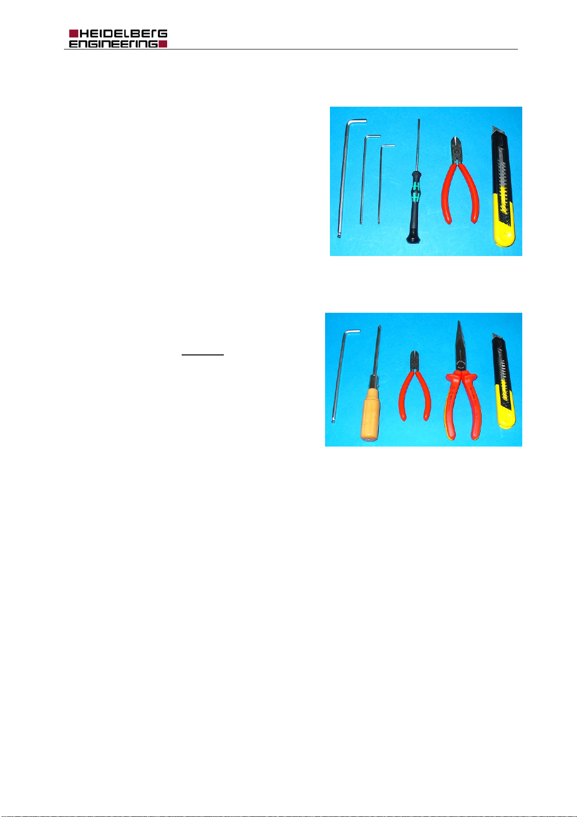
3 Tools
The following tools are required:
Allen wrenches
o 5 mm
o 3 mm
o 2.5 mm
Screwdriver for slotted head screws 3 mm
Wire cutter
Cutter.
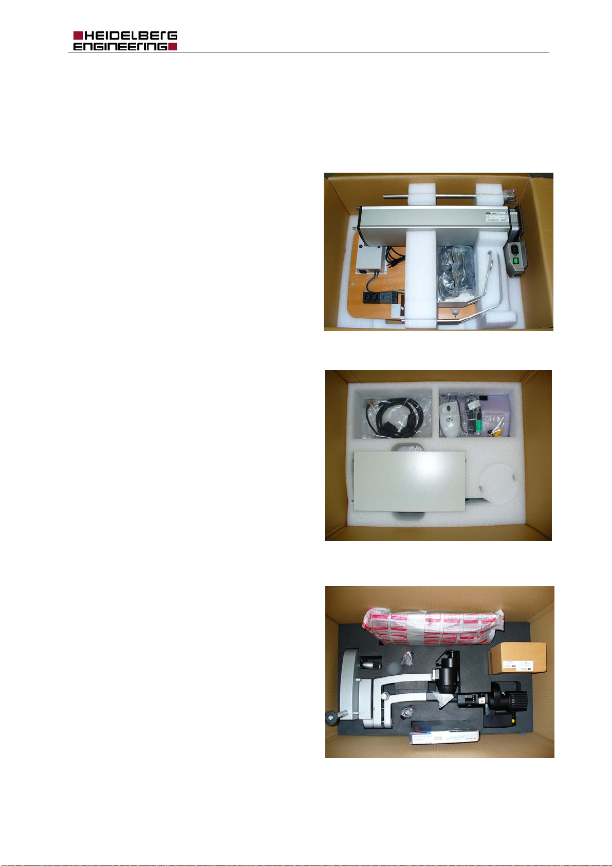
For the assembly of the optional printer table, following
the tools are required:
Allen wrench with ball head
5 mm
Screwdriver for recessed head screws
Wire cutter
Long nose pliers
Cutter.
Pic. 2 Tools for installation of SL-OCT
Pic. 3 Tools for the assembly of the printer table
Page 8
SL-OCT Installation Manual
Art. No.: 18107 Page 8 of 42
4 Unpacking the system
The SL-OCT is delivered in three cardboard boxes – lift table, OCT-box, and slit lamp. The packing lists
for each box are listed in section 10 Appendix C.
4.1 Lift table
The lift table package contains three layers:
1. Cable conduit, column, keyboard fixation
arm, and monitor fixation arm.
2. Cables, wheels, and table top.
3. Foot.
Pic. 4 Cardboard box containing the lift table
4.2 OCT-box
The OCT-box package contains two layers:
1. Folder with operating instructions etc., and
mouse pad.
2. Cables, mouse, dust cover, protective caps,
replacement fuses, OCT-box.
4.3 Slit lamp
The slit lamp package contains two layers:
1. Head rest in a separate cardboard box.
2. Monitor, slit lamp with permanently mounted
scanner-box, slit lamp accessories in a
separate cardboard box, eyepieces for the
microscope, and keyboard.
Pic. 5 Cardboard box containing OCT-box
Pic. 6 Cardboard box containing slit lamp
Page 9

SL-OCT Installation Manual
Art. No.: 18107 Page 9 of 42
5 Installation
The installation of the SL-OCT unit is started with the build up of the lift table. The next part is the
assembly of the OCT-box onto the lift table. Afterwards, the slit lamp including the permanently mounted
scanner-box is installed onto the lift table. At the end of the installation procedure, test measurements
are carried out to ensure correct operation of the device.
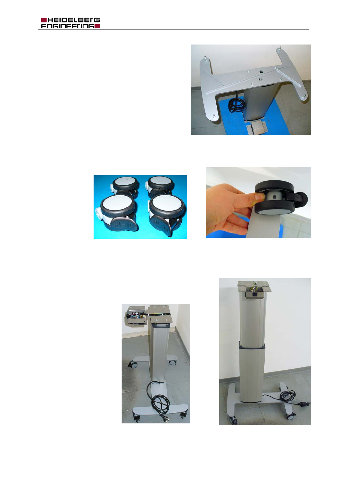
5.1 Lift table
The first step is the assembly of foot and column. Take
the column out of its package and place it on top onto
e.g. a cellular plastic backing (see Pic. 7).
cellular plastic backing
Pic. 7 Column prepared for assembly of foot
Remove the four Allen screws (M6 x 40) and spring washers needed for
the assembly of the foot.
All screws and washers necessary for assembly are provided,
slightly screwed into their respective screw holes!
Control the cable laying. The mains cable of the column must lay in
the slit (see Pic. 9).
Pic. 8 Premounted screws for
assembly of the foot
Pic. 9 Cable laying of mains cable
Page 10
SL-OCT Installation Manual
Art. No.: 18107 Page 10 of 42
Mount the foot onto the column (see Pic. 10). The
longer part of the foot must be oriented towards the the
cable outlet of the column. The computer screen will
later be mounted onto this side of the table. Therefore,
the correct orientation of the foot is essential for the
stability of the table.
Pic. 10 Foot onto column mounted
Now clip in the four wheels onto the foot.
Pic. 11a Wheels
Pic. 11 Clip in the wheel
Turn around column and mounted foot (see Pic. 12a). Then, connect mains and lift the column until the
stop at end (see Pic. 12).
Attention: Be very careful not to touch the cables in the open
control console as they are alive! As soon as the column is
lifted, disconnect the mains!
Pic. 12a Column not lifted
Pic. 12 Column lifted till stop at end
Page 11

SL-OCT Installation Manual
Art. No.: 18107 Page 11 of 42
After disconnecting mains, the tabletop is prepared. Remove the screws and washers from the screw
holes for the column (M6 x 25 and spring washers) and control console (M6 x 16 and spring washers)
(see Pic. 13 red and green).
Multible power
socket
Assembly of
head rest
Assembly of
control console
Assembly of
column
Pic. 13 Table top (bottom) with premounted screws and washers
Mount the tabletop onto the column. Use the short
Allen screws for the console and the long ones for
the column.
Assembly of
monitor fixation
Pic. 14 Mounting of table top onto the column
If there is an optional printer arm delivered with the SL-OCT, it can be assembled at this state of the
installation or at the end of the assembly procedure. Please refer to section 5.2.
Page 12
SL-OCT Installation Manual
Art. No.: 18107 Page 12 of 42
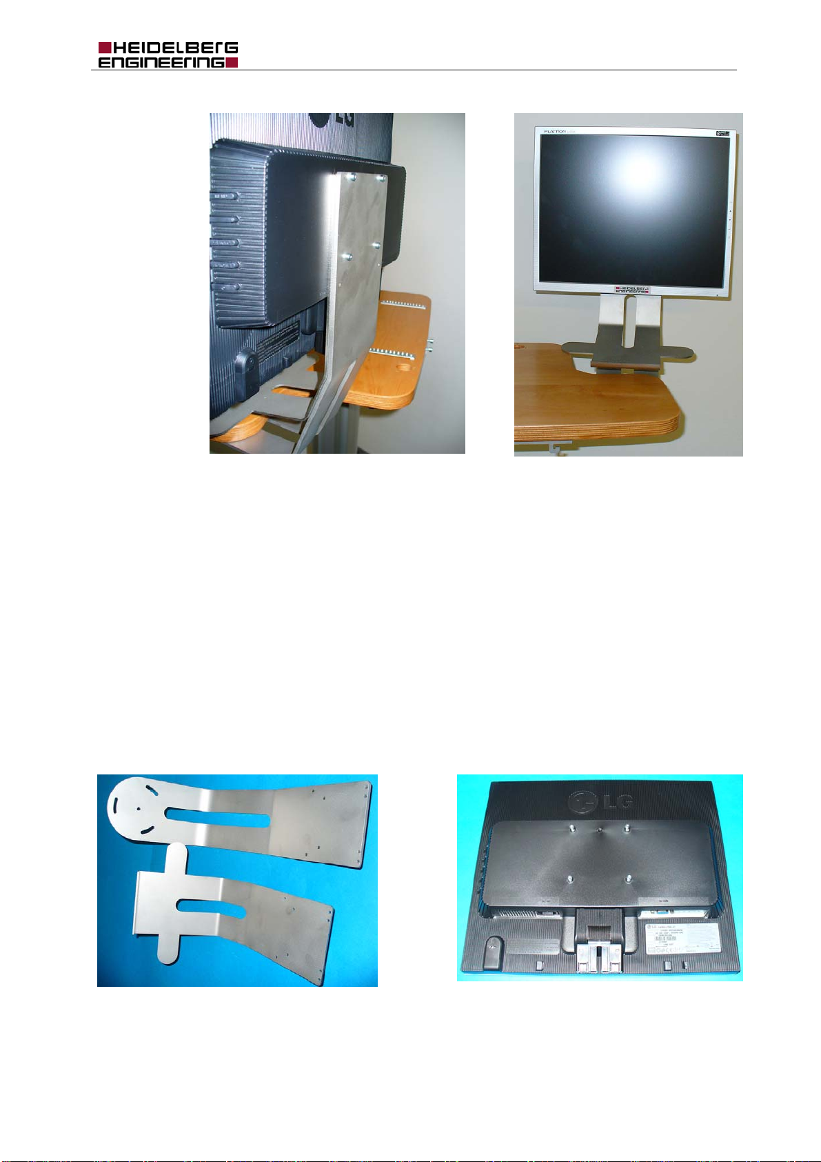
Pic. 15a rear side of mounted monitor unit
Pic. 15 Mounted monitor including keyboard
fixation arm
The computer screen is mounted together with the keyboard fixa tion arm on its fixation arm. The other
end of the monitor fixation arm is mounted beneath the tabletop (see Pic. 15a and Pic. 15).
There are two possible ways for mounting the monitor unit onto the table:
1. Premounting of monitor arm, keyboard arm, and monitor before assembly of the whole unit onto
the lift table.
This is recommended if several persons are installing the device together.
2. Premounting of monitor arm and lift table before assembly of keyboard arm and monitor.
This might be more comfortable if there is a single person installing the device. It is easy to
adjust the monitor fixation arm with one hand while looking beneath the tabletop and mounting
the screws. Handling the whole premounted unit with one hand while adjusting the screws
beneath the table needs more strength.
Avoid touching the surface of the screen.
Pic. 16a Monitor arm and keyboard arm
Pic. 16 Rear side computer screen with its screws
Page 13
SL-OCT Installation Manual
Art. No.: 18107 Page 13 of 42
1. Premounting of monitor unit
Put the computer screen with the screen facing downwards
onto a table parallel to the table’s edge (see Pic. 16).
Remove the screws (Allen screws M4 x 20). Place the
keyboard arm onto the monitor with the angled part
hanging down. Now place the monitor arm on top and
screw all parts together (see Pic. 17).
Pic. 17 Mounted monitor unit
Remove the screws from the tabletop (see magenta arrow in Pic. 13 and
Pic. 18).
Pic. 18 rear side of tabletop in detail
Place the monitor unit so that the keyboard arm is on top of the lift table and
the angled part of the monitor arm is beneath the table (see Pic. 15a).
Assembly the 4 Allen screws (M6 x 20). Adjust the computer screen into the
right position by turning it slightly around the middle screw before fastening
the screws.
2. Premounting of the monitor arm
Remove the screws from the tabletop (see Pic. 13 magenta
and Pic. 18). Assemble the monitor arm (see Pic. 16a) at the
lift table (see Pic. 20).
Do not fully fasten the screws (M6 x 20) until the computer
screen is mounted and adjusted.
Plug in mains and lower the lift table to a convenient height.
Pic. 19 Mounted monitor arm
Pic. 20 Mounted monitor arm
Page 14

SL-OCT Installation Manual
Art. No.: 18107 Page 14 of 42
Remove the screws from the rear side of the monitor (see Pic. 16).
Place the keyboard arm in front of the monitor arm and stick the
screws (M4 x 20) through the holes (see Pic. 21) so that it is hanging
on the screws.
Pic. 21 Keyboard arm hanging on screws
Now carefully place the monitor in front of the keyboard arm and fasten the screws (M4 x 20). Adjust the
computer screen to the right position by turning it slightly around the middle screw before fastening the
screws beneath the table.
Now continue with the installation of the headrest.
If necessary, plug in mains and lift the table to comfortable height.
Remove the two Allen screws (M6 x 20) of the headrest assembly from
the edge of tabletop (see turquoise arrow in Pic. 13 and Pic. 22). Loosen
one of the knurled screws and remove the second. Swing the protective
cover aside (see Pic. 22a).
Pic. 22a Protective cover of headrest’s
electrical plug
Pic. 22 Assembly of headrest beneath table
Page 15

SL-OCT Installation Manual
Art. No.: 18107 Page 15 of 42
Connect the electrical plug of the headrest and assemble
the headrest onto the lift table.
Swing back the protective cover (see Pic. 22b) and fasten
the knurled screws again.
Grab handles
and locking
screws
Pic. 22b Protective cover of the
headrest’s electrical plug
Pic. 23 Headrest
Loosen the locking screws at the inner side of the headrest a bit, screw in the grab handles, and fasten
the locking screws again (see Pic. 23 red).
Pic. 24 Rail covers
Pic. 24a Rail cover on the right side
Fit the rail covers onto the rails (see Pic. 24 and Pic. 24a). The rail cover with the cable bracket is on the
left side from operator’s view.
The rail cover at the cable conduit’s side (right) must be mounted before the cable conduit is
assembled! (See section 5.3 below)
Page 16

SL-OCT Installation Manual
Art. No.: 18107 Page 16 of 42
5.2 Optional printer table
Heidelberg Engineering recommends placing the
printer on a separate table near the SL-OCT
unit.
If this is not possible, the optional printer table
can be assembled to the unit with a fixation arm
(see Pic. 25).
Note: While printing using the optinal printer
table, it is not possible to take
measurements due to the vibrations of
the printer.
Pic. 25 Optional printer table with printer
Heidelberg Engineering recommends using the following printer types:
Hewlett Packard D4200 family
Hewlett Packard 5900 family.
For both printer series, the software drivers are preinstalled on the SL-OCT built-in computer.
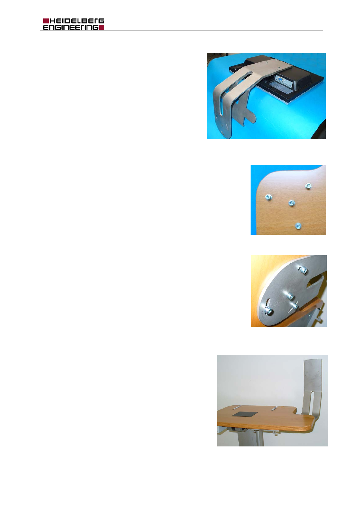
First, the fixation arm is mounted onto the
printer tabletop (see Pic. 26 and Pic. 27).
Pic. 26 Printer table fixation arm
The image to the right (Pic. 27) shows the rear side of
the printer table with premounted cable brackets for the
assembly of the printer’s power supply and premounted
recessed countersunk flat head wood screws (4 x 16
mm) for the assembly of the arm.
Remove the four recessed head screws and mount the
arm onto the table (see Pic. 28).
Pic. 27 Rear side of the printer tabletop
Page 17

SL-OCT Installation Manual
Art. No.: 18107 Page 17 of 42
Pic. 28 Rear side of the printer table with fixation arm
The fixation arm is assembled onto the SL-OCT lift table
with three Allen screws (M6 x 12). Pic. 29 shows the
screw holes beneath the SL-OCT tabletop near the slit
lamp power supply.
Pic. 29 Detail of SL-OCT table top with screw holes for the
printer fixation arm
The assembly must start with the single screw near the
table’s edge. Screw in this screw first without fastening it,
then mount the other two screws.
After adjusting the table, fasten at first the single screw
(see Pic. 30 and Pic. 31) then the others.
Note: The single screw near the table’s edge can only be
fastened with an Allen screwdriver with ball head
.
Pic. 31 Detail of the single screw near the table’s edge
Pic. 30 Assembly of the printer fixation arm
Page 18

SL-OCT Installation Manual
Art. No.: 18107 Page 18 of 42
Now place the printer on the table as shown in Pic. 25.
Install the printer’s power supply beneath the printer
table using the premounted cable brackets and the long
cable ties (see Pic. 32).
Pic. 32 Power supply printer
Thread the USB cable and
the printer’s power cord
through the printer arm (see
Pic. 33a and b) - long nose
pliers may be helpful.
Pic. 33a Printer cable at the SL-
OCT table
Pic. 33b Cable of the printer
Connect the USB cable to the SL-OCT computer and the power cord to the multiple power socket. Use
the short cable ties for a proper cord placing.
If necessary the mains connector of the printer must be replaced by an
IEC60 320-2-2 connector. The connector is delivered with the printer table.
Only a qualified person is allowed to replace the plug.
Pic. 34 IEC60 320 power plug
Page 19

SL-OCT Installation Manual
Art. No.: 18107 Page 19 of 42
5.3 OCT-box
Attention: A glass fiber is permanently connected to the OCT-box – handle the unit with care!
Do not buckle the glass fiber!
Before taking the OCT-box out of the
package, remove the cellular plastic
stopper from the glass fiber packaging
(see Pic. 35).
Pic. 35 OCT-box in the package with stopper in the hole for the glass fiber
Check if the fuses are correctly dimensioned
for the used mains voltage (see Pic. 36). The
default built in fuses (T 2.5A /250V) are for
230Vac.
For the use with 110Vac the needed 5A fuses
(T 5,0A / 250V) are in the package (see
section 10.2 Appendix C Packing lists).
Pic. 36 Fuses of the OCT-box
Replace the fuses (see Pic. 37a and b).
Unscrew the carriers from the fuse bases and
pull out the fuses.
Stick the 5A fuses into the carriers and screw them
into the fuse bases of the OCT-box.
Pic. 37a Removal of a fuse
Pic. 37b Fuse in fuse carrier
Page 20

SL-OCT Installation Manual
w
Art. No.: 18107 Page 20 of 42
The Allen screws in the OCT-box (M3 x 10) should show 6 – 8 mm thread as shown in Pic. 38a.
Pic. 38a OCT-Box with premounted screws
Pic. 38b Hook for hanging the OCT-box
beneath the table
Hang the OCT-box onto the hooks. The switch must be on the operator’s side of the table. Fasten the
four Allen screws (M3 x 10) (see Pic. 38 a-d).
Pic. 38c OCT-Box hanging beneath the table
Pic. 38d OCT-Box with fastened scre
Page 21

SL-OCT Installation Manual
r
Art. No.: 18107 Page 21 of 42
Pic. 39a Scanner cable
The next step is the installation of the scanner cable (see
Pic. 39a).
When looking from the patients side of the device, the
connectors of the OCT-box are located at the left side of the
box (see Pic. 60). All connectors are labeled.
The sub-D connector of the cable is connected to the OCTbox (see Pic. 39b). The other end of the cable is pushed
through the hole in the tabletop together with the fiber plug
(see Pic. 40).
Remove the Allen screws
(M4 x 35) and washers from
the cable conduit (see Pic.
41a).
Pic. 39b Scanner cable connected to OCT-box
Pic. 40 Scanner cable and glass fiber are pushed
through the hole in the tabletop
Pic. 41a Cable conduit
Pic. 41b Fiber and electrical connecto
Pic. 41c Put first fiber and second electrical
connector into the conduit
Both fiber and scanner cable together are threaded through the cable conduit (see Pic. 41b). The fiber
connector must pass the tube first (see Pic. 41b and c). The scanner cable is stiff enough to be pushed
through the tube taking the fiber with it.
Page 22

SL-OCT Installation Manual
Art. No.: 18107 Page 22 of 42
Stick the cable conduit into the hole in the table (see Pic. 42). Do not screw it at
this point of time.
Pic. 42 Cable conduit mounted onto the table
First mount the black plastic flexible tube onto fiber and scanner cable (see Pic. 43a and b).
Pic. 43a Plastic tube and clip
Pic. 43b Two parts of plastic tube
The flexible tube consists of two parts, which are clipped together (see Pic. 43b). Part it and fit in fiber
and scanner cable near the connectors into the slit of the inner tube (see Pic. 44). The more flexible,
thinner glass fiber must be at the inner side of the tube.
Pic. 44 Fit in glass fiber and scanner cable into the slit of the tube
Now carefully pull the connectors and the tube in the directions indicated in picture 45 in order to slide the
cables into the tube (see Pic. 45).
Page 23

SL-OCT Installation Manual
Art. No.: 18107 Page 23 of 42
Pic. 45 Glass fiber and scanner cable are sliding into the tube
Clip the outer part of the plastic tube (see Pic. 43) onto the
inner part which is assembled on the cables (see Pic. 46).
Pic. 46 Closing the flexible tube
Assemble the clip (see Pic. 43a) at the end of the flexible tube (see
Pic. 47).
Pic. 47 Clip at the end of the flexible tube
Page 24

SL-OCT Installation Manual
Art. No.: 18107 Page 24 of 42
The clip is screwed into the conduit by turning
the conduit
around (see Pic. 48a).
Attention: Do not rotate the clip! If the clip
and flexible tube are rotated, the glass fiber
will be drilled. This will cause a loss of
signal quality!
Pic. 48a Screwing of the clip
into the conduit
Pic. 48b Mounted clip
Pic. 49 Flexible tube and clip assembled
When the flexible tube and the clip are mounted (see Pic. 48b and Pic. 49) the cable conduit must be
fixed.
The rail cover must be at its
place before assembling the
cable conduit!
Lift the basis of the conduit
about 2 or 3 mm from the
tabletop (see Pic. 50a).
Now it is possible to see the
screw holes for adjusting
and fastening the screws
(see Pic. 50b)
Pic. 50a Assembly of cable conduit
Pic. 50b Tightened cable conduit
Page 25

SL-OCT Installation Manual
r
Art. No.: 18107 Page 25 of 42
5.4 Slit lamp
Swing the right rail cover to the side as shown in Pic. 51. Take
the slit lamp out of its package and place it on the tabletop so that
the wheels fit onto the rails.
Take the two eyepieces out of the package and push them into
their holders in the microscope arm.
Cover the rails with the rail covers.
Pic. 51 Slit lamp standing onto the table
Remove the transport dust cover from the slit lamp’s mirror (see Pic. 52
red).
Attention: Do not touch the mirror!
Remove the transport protection shown in Pic. 52 yellow. Use the slit width
control to loosen the protection piece and remove it.
Take the protective cover (see Pic. 52a) out of the box containing the slit
lamp accessories and put it onto the basis of the slit lamp arm (see magenta
arrow in Pic. 52).
Protective
cover
Pic. 52a Protective cove
Slit width
control
Pic. 52 Slit lamp’s arm with
transport protections
Page 26

SL-OCT Installation Manual
Art. No.: 18107 Page 26 of 42
5.5 Electrical and fiber connections to the slit lamp
Three connectors are located on the head of the slit lamp (see
Pic. 53):
1. The glass fiber is connected to the scanner-box.
2. The scanner cable is also connected to the scanner-box.
3. The lamp cable from the headrest is connected to the
illumination unit.
Attention: Do not touch the head of the fiber!
Handle the fiber with care.
Pic. 53 connectors of the scanner-box
Remove the protective caps from the
connectors on top of the scanner-box
(see Pic. 54a and b).
The connector next to the illumination
unit of the slit lamp is a fiber socket with
a notch (see also Pic. 56). The
electrical connector for the scanner
cable next to the fiber socket has a
nose.
Pic. 54a connector on top of
scanner box with protective
caps
Pic. 54b Left: electrical socket, right: fiber socket
Remove the protective
cap from the glass
fiber plug (see Pic.
55a and b).
The fiber plug has a
nose (see also
Pic. 55a fiber plug with protective cap
Pic. 55b fiber plug without protective cap
Attention: Do not touch the head of the fiber! Dirt on the head of the fiber will cause a lost of signal
quality!
Page 27

SL-OCT Installation Manual
r
Art. No.: 18107 Page 27 of 42
Plug in the glass fiber as shown in Pic. 56. Fit the nose of the fiber plug into the notch of the socket. Try
to slightly turn the plug in the socket, to check if nose and notch are correctly placed. Be careful not to
twist the glass fiber, as rotating the glass fiber may damage it. If it is not possible to rotate the plug,
fasten the clamping nut.
nose
notch
Pic. 56 Nose and notch of the fiber connection
Attention: Do not buckle the glass fiber!
A kink in the glass fiber will lead to a
loss of signal quality! A break of the
fiber will lead to a breakdown of the
device.
Pic. 57a buckled fibe
Pic. 57b Glass fiber well guided
Connect the scanner cable to the scanner-box. The little nose of the socket (see Pic. 54a and b) must fit
into the notch of the plug. Fasten the clamping nut of the plug.
Connect the power for the slit lamp illumination to the head of the slit lamp (see Pic. 53).
Connect the power of the slit lamp to the slit lamp basis.
Remove the cable bracket from the rail cover with a screwdriver
for slotted head screws. Fix the cable with the bracket (see Pic.
58).
Pic. 58 Power supply for the slit lamp
Page 28

SL-OCT Installation Manual
y
Art. No.: 18107 Page 28 of 42
5.6 Electrical connections to the OCT-box
Place the keyboard onto the keyboard fixation arm, the
mouse pad onto the table, and the mouse onto the
mouse pad (see Pic. 59).
Pic. 59 Keyboard and mouse
When looking from the patients side of the
device, the connectors of the OCT-box are
located at the left side of the box (see Pic.
60). All connectors are labeled.
The scanner is already connected (see Pic.
39).
Connect monitor, keyboard, and mouse.
If the monitor needs dc voltage, the 12V
connector is used. If the monitor needs ac
voltage refer to next section 5.7.
Pic. 60 Connectors of the OCT-box
USB, LAN, and RS232 are optional connectors for computer periphery.
The following images show the connections of the monitor on the rear side. In case of dc power refer to
Pic. 61a. In case of ac power supply refer to Pic. 61b.
Pic. 61a Monitor with dc power suppl
(bottom) and VGA connection (top)
Pic. 61b Monitor with ac power supply (left) and
VGA connection (right)
Page 29

SL-OCT Installation Manual
Art. No.: 18107 Page 29 of 42
5.7 AC connections
The sockets for ac power are located on both sides of the
lift table’s control console (see Pic. 62).
Pic. 62 AC socket at control console
The following ac cables are needed:
1. Power-in to multiple socket (length 0.35 m)
2. Power to power supply slit lamp (length 0.30 m)
3. Power to OCT-box (length 0.32 m)
4. Power to monitor if monitor needs ac power
(length 1.05 m)
5. Optional: power to printer (refer to section 5.2).
Pic. 63 AC cables
The image to the right (Pic. 64) shows the power supply
of the multiple power socket. The mains cord is
connected to the console (see Pic. 62) and to the input of
the multiple socket.
The multiple power socket provides four equal outputs.
Power in
Pic. 64 Multiple power socket with power-in connection
The image to the right (see Pic. 65) illustrates the power
distribution with the multiple power socket. The optional power
connection to the printer is not shown.
to control console of column
Pic. 65 Power distribution with multiple socket
Page 30

SL-OCT Installation Manual
Art. No.: 18107 Page 30 of 42
Use the protective cover
of the headrest and the
premounted cable
bracket with a cable tie
for a proper placement
of the cables (see Pic.
66a and b).
Pic. 66a cable bracket
Pic. 66b placement of cables
5.8 Cleaning
If necessary, clean the mirror of the slit lamp
.
We recommend to remove dust using compressed air, which is commercially available in aerosol cans.
Fingerprints can be removed with a small amount of ethanol and lens cleaning tissue. Contact
Heidelberg Engineering support for a detailed description for the cleaning of mirror and glass fiber head.
If necessary, clean the computer monitor
.
Again, the best way to remove dust is compressed air. In order to remove fingerprints use special
cleaners for TFT computer screens, e.g. a special tissue with alcohol free cleaning fluid.
For information on maintenance, please refer to the SL-OCT Operation Instructions.
Page 31

SL-OCT Installation Manual
Art. No.: 18107 Page 31 of 42
6 Test measurement
Start up the system as described in the SL-OCT Operating Instructions. Wait about 10 minutes until the
device has warmed up. Start the Heidelberg Eye Explorer program and open the acquisition window.
Pic. 67a protective cover
Remove the protective cover from the slit lamp and fit in the test rod of the
slit lamp (see Pic. 67 and Pic. 68).
The test rod is an accessory of the slit lamp and can be found in the
accessories box.
Pic. 67b Slit lamp’s rod
Pic. 68 Installation of the slit lamp’s test rod
Page 32

SL-OCT Installation Manual
Art. No.: 18107 Page 32 of 42
Start the acquisition. Adjust the rod until a horizontal bright white line is visible in the upper third of the
OCT display (see Pic. 69).
If the OCT image of the rod is not shining bright or located at a wrong position in the B-scan, refer to
section 8 Appendix A Troubleshoot.
Pic. 69 Measuring the slit lamp’s test rod
When the test image of the rod is correct, stop the data acquisition and remove the test rod from the slit
lamp. Cover the holding of the rod with the protective cover again.
Now the installation process of the SL-OCT device is finished.
Page 33

SL-OCT Installation Manual
Art. No.: 18107 Page 33 of 42
7 Disassembly of a SL-OCT unit
This section contains special notes for the disassembly of the SL-OCT unit. Basically the disassembly is
the installation procedure in backwards order.
If packages for the unit are lost, contact Heidelberg Engineering for replacement. In any case the original
cardboard boxes must be used for transportation of the SL-OCT unit.
Please slightly screw all screws and washers after disassembly in their screw holes again. Loose screws
in the cardboard boxes may damage the SL-OCT unit!
Removing the fiber connection
Attention: Do not buckle the glass fiber!
Do not touch the head of the fiber!
Before opening the fiber connection on top of the scanner-box, be sure that the protection cap for the
fiber plug is ready to hand. As soon as the plug is disconnected, protect the fiber head with the cap (see
Pic. 55a).
If necessary there are replacement caps in the package of the OCT-box.
Packaging the slit lamp into the cardboard box
Attention: Do not touch the mirror!
First, remove the eyepieces from the slit lamp’s microscope.
Mount the protective caps onto the connectors on top of the scanner-box. If necessary, there are
replacement caps in the package of the OCT-box.
Protect the slit lamps mirror with a lens cleaning tissue as shown in Pic. 52.
Protect the slit lamp against vibrations with the transport protection also shown in Pic. 52.
Lower the slit lamp as low as possible by turning around the control lever.
Opening the plastic clip
Use a screwdriver for slotted head screws for opening
the clip as shown in Pic. 70. Block the locking
mechanism with the screwdriver and part the slit of
the clip.
Pic. 70 Opening the plastic clip
Page 34

SL-OCT Installation Manual
Art. No.: 18107 Page 34 of 42
Removing the flexible plastic tube
Attention: Do not buckle the glass fiber! Handle the fiber with care.
The flexible plastic tube consists of two pieces that are clipped together. First remove the outer part.
Then take both cables – glass fiber and scanner cable – in one hand and pull them out of the slit of the
inner tube.
Putting the column into the cardboard box
After the tabletop is removed from the column, connect mains and lower the column as low as possible.
Attention: Be very careful because cables in the open control console are alive!
The column must be telescoped to the lowest position before it can be put into the cardboard box.
Removing the wheels from the foot
First disassemble the column from the foot.
For removing the wheels from the foot, a solid screwdriver for slotted head
screws at least 6 mm is required. Place the foot on a table near the table’s
edge. Insert the screwdriver between nut and top of the wheel as shown in Pic.
71 and lever the wheel from the pin (see arrow).
Pic. 71 Disassembly of wheel
Page 35

SL-OCT Installation Manual
Art. No.: 18107 Page 35 of 42
8 Appendix A: Troubleshooting
If parts are missing, contact Heidelberg Engineering. For missing screws, please refer to section 9
Problem Cause Measures / Solution
The tube of the cable conduit in
the base is loose.
The lift column is not working.
The Allen set screw holding the
tube is loose.
Tighten the screw in the base with
an Allen key 2 mm.
Mains are not properly connected. Check the mains connection.
Mains cord is defect.
Check the mains cord.
Mains voltage differs from the
specified voltage for the column.
Check the column specifications.
Contact Heidelberg Engineering.
Other cause. Contact Heidelberg Engineering.
Device is switched on and the
green power switch is not
shining.
Device is switched on and
monitor stays dark
Device not connected or
connection with mains is
defective.
Check mains connectors.
Is the multiple socket connected to
the column?
Is the main switch at the control
console of the column switched
on?
Cable connections between
Check the cable connection.
monitor and OCT-box are
defective.
Monitor is switched off. Use the power switch of the
monitor to turn on the screen.
Other cause. Contact Heidelberg Engineering.
Page 36

SL-OCT Installation Manual
Art. No.: 18107 Page 36 of 42
Computer is booted but mouse /
keyboard does not work.
The test measurement is
Connection of mouse / keyboard
is defective.
SL-OCT is not scanning.
strange.
Glass fiber is not properly
connected.
Check the connection of the
mouse / keyboard plug at the
OCT-box and reboot the
computer.
Shut down the computer and
check scanner cable. Reboot the
computer and start measurement.
Check the fiber connection, see
section 5.4 Pic. 56.
Page 37

SL-OCT Installation Manual
Art. No.: 18107 Page 37 of 42
9 Appendix B: List of screws
All screws required are delivered with the system and premounted in their screw holes.
Allen screw
metric thread
length in mm
M3 x 10 4 - OCT-box - table
M4 x 20 4 - Monitor- and keyboard arm - monitor
M4 x 30 3 Flat washer Cable conduit - table
M6 x 12 optional 4 - Optional printer arm - table
M6 x 16 4
M6 x 20 4 - Monitor arm - table
M6 x 25
M6 x 40 4
Recessed
countersunk flat
head wood screws
4 x 16 optional
All used screws are commercially available.
Quantity Washer Position
Spring
washer
Control console column - tabletop
2 - Headrest - table
4
Spring
washer
Spring
washer
Column - tabletop
Foot - column
4 - Optional printer arm – printer tabletop
Page 38

SL-OCT Installation Manual
Art. No.: 18107 Page 38 of 42
10 Appendix C: Packing lists
10.1 Lift table
Part
Foot 1
Wheel 4
Column 1
Tabletop 1
Fixation arm for monitor 1
Fixation arm for keyboard 1
Cable conduit 1
Quantity
Page 39

SL-OCT Installation Manual
Art. No.: 18107 Page 39 of 42
Cable 0.30 m power supply slit lamp
Cable 0.32 m power supply OCT-box
Cable 1.05 m power supply monitor
Cable 0.35 m power supply multiple socket
Flexible plastic tube
1
1
1
1
1
Plastic clip 1
Rail cover 2
10.2 OCT-box
Part
Quantity
OCT-box 1
Protection cap mounted on fiber plug 1
Mouse 1
Mouse pad 1
Scanner cable 1
Signal cable monitor (VGA) 1
Page 40

SL-OCT Installation Manual
Art. No.: 18107 Page 40 of 42
Folder SL-OCT operating instructions 1
Dust cover 1
Replacement protection cap scanner plug-in
Replacement protection cap glass fiber plug
Replacement protection cap fiber plug-in
1
1
1
Replacement fuse 5.0 A 2
10.3 Slit lamp
Part
Quantity
Slit lamp 1
Eye piece 2
Headrest 1
Page 41

SL-OCT Installation Manual
Art. No.: 18107 Page 41 of 42
Headrest handles 2
Keyboard 1
Monitor 1
Dust cover slit lamp 1
Test rod 1
Protective cover 1
Breath-shield 1
Chinrest papers 1 package
Page 42

SL-OCT Installation Manual
Art. No.: 18107 Page 42 of 42
10.4 Optional printer table
Part
Quantity
Tabletop 1
Fixation arm 1
Cable tie 14 mm 2
Cable tie 37 mm 2
Screw M5 x 12 3
Plug IEC60 320 1
 Loading...