

HEIDELBERG Nexscan F 4100, Nexscan F 4200 Operation

Nexscan F 4100/F 4200
Operation
Edition September 2000
Order No. 05573483
ABC

I
mprint/Company
Add
ress
Copyright © 2001 Heidelberger
Druckmaschinen Aktiengesellschaft.
No part of this book may be reproduced without prior written permission.
. . . . . . . . . . . . . . . . . . . . . . . . . . . . . . . . . . . . . . . . . . . . . . . . . . . . . . . . . . . . . . . . . . . . . . . . . . . . .
Agfa® is a registered trademark of
Bayer Corporation and its subsidiary
companies.
®
Newcolor
and Nexscan
trademarks of Heidelberger
Druckmaschinen AG.
Kodak
, Newcopix®, LinoColor®
®
are registered
®
is a registered trademark of
Eastman Kodak Company.
®
Apple
, the Apple Logo®, AppleTalk®,
®
ColorSync
. . . . . . . . . . . . . . . . . . . . . . . . . . . . . . . . . . . . . . . . . . . . . . . . . . . . . . . . . . . . . . . . . . . . . . . . . . . . . . . . . . .
, EtherTalk®, LaserWriter®,
Heidelberger Druckmaschinen AG
Dr.-Hell-Straße
D-24107 Kiel
Phone +49 (4 31) 3 86-0
Fax +49 (4 31) 3 86-1380
http://www.heidelberg.com/
®
Macintosh
are registered trademarks of Apple
and Power Macintosh®
Computer, Inc.
Other company names, product
names and trademarks not expressly
mentioned in this manual are
trademarks or registered trademarks
of the corresponding manufacturers
and fall within the regulations
regarding the protection of
trademarks.
Important notice:
We are dedicated to improving and
enhancing our products. For this
reason, we reserve the right to make
changes without notice.
Heidelberger Druckmaschinen AG
assumes no responsibility for
information and description as far as
third-party products are concerned.
The information contained in this
manual about performance and
concerning application of our
products is not legally binding as it
does not constitute a written
contract of features.
If any problems occur with the
product described in this manual,
please contact the Heidelb erg agency
which is responsible for you.
Order No. 05573483
Edition September 2000
speed as well as technical data

ABC
Table of Contents
Table of Contents
Before you start ...
Notes on Technical Safety . . . . . . . . . . . . . . . . . . . . VII
Designated Use . . . . . . . . . . . . . . . . . . . . . . . . . . . . . VII
General . . . . . . . . . . . . . . . . . . . . . . . . . . . . . . . . . . . . VII
Prerequisites . . . . . . . . . . . . . . . . . . . . . . . . . . . . . . . VIII
Other Documentation . . . . . . . . . . . . . . . . . . . . . . . . VIII
About This Documentation . . . . . . . . . . . . . . . . . . . . IX
Conventions Used in This Manual . . . . . . . . . . . . . . . . IX
Important Information . . . . . . . . . . . . . . . . . . . . . . . . . . X
Influence of Magnetic Fields on the Monitors . . . . . X
Any Comments on this Documentation? . . . . . . . . . XI
HEIDELBERG Online . . . . . . . . . . . . . . . . . . . . . . . . XII
1 Unpacking and Installing
Dear Customer . . . . . . . . . . . . . . . . . . . . . . . . . . . . . 1–1
Power connection . . . . . . . . . . . . . . . . . . . . . . . . . . . 1–1
Scope of Delivery . . . . . . . . . . . . . . . . . . . . . . . . . . . 1–1
Unpacking and Installing . . . . . . . . . . . . . . . . . . . . . 1–2
2 Connecting
Installation . . . . . . . . . . . . . . . . . . . . . . . . . . . . . . . . . 2–1
Connecting the Nexscan F 4100/F 4200 to the
workstation . . . . . . . . . . . . . . . . . . . . . . . . . . . . . . . . . 2–1
Connecting the Nexscan F 4100/F 4200 to the power
supply . . . . . . . . . . . . . . . . . . . . . . . . . . . . . . . . . . . . . 2–3
Switching on the Nexscan F 4100/F 4200 . . . . . . . . . 2–6
Installing the Newcolor Software . . . . . . . . . . . . . . . . . 2–6
Installing the LinoColor Software . . . . . . . . . . . . . . . . 2–6
Installing Calibration Data . . . . . . . . . . . . . . . . . . . . . . 2–7
3 Product Description
General view Nexscan F 4100/F 4200 . . . . . . . . . . . 3–1
Product and Performance Features of the
Nexscan F 4100/F 4200 . . . . . . . . . . . . . . . . . . . . . . . 3–2
Overall configuration . . . . . . . . . . . . . . . . . . . . . . . . 3–4
Nexscan F 4100/F 4200 – Operation I

Table of Contents
ABC
Scanning principle . . . . . . . . . . . . . . . . . . . . . . . . . . 3–5
Power Switch . . . . . . . . . . . . . . . . . . . . . . . . . . . . . . 3–7
Pilot Lamp . . . . . . . . . . . . . . . . . . . . . . . . . . . . . . . . . 3–7
Scanning Progress Indicator . . . . . . . . . . . . . . . . . 3–8
Universal tray . . . . . . . . . . . . . . . . . . . . . . . . . . . . . . 3–8
Mounting Rail . . . . . . . . . . . . . . . . . . . . . . . . . . . . . . 3–9
Scanning Area . . . . . . . . . . . . . . . . . . . . . . . . . . . . . 3–9
Screens . . . . . . . . . . . . . . . . . . . . . . . . . . . . . . . . . . . 3–9
Scales . . . . . . . . . . . . . . . . . . . . . . . . . . . . . . . . . . . . 3–9
Scanning Speed . . . . . . . . . . . . . . . . . . . . . . . . . . . 3–10
Illumination of originals . . . . . . . . . . . . . . . . . . . . . 3–10
4 Working with the Nexscan F 4100/F 4200
Operating Sequence . . . . . . . . . . . . . . . . . . . . . . . . 4–1
Preparation for Production . . . . . . . . . . . . . . . . . . . . . 4–1
Preparing the Tray . . . . . . . . . . . . . . . . . . . . . . . . . . . 4–2
Positioning the Originals . . . . . . . . . . . . . . . . . . . . . . . 4–2
On the Glass Plate in the Device . . . . . . . . . . . . . . 4–2
On the Universal Tray . . . . . . . . . . . . . . . . . . . . . . . 4–3
Securing the Originals . . . . . . . . . . . . . . . . . . . . . . . . 4–4
Inserting the Tray . . . . . . . . . . . . . . . . . . . . . . . . . . . . 4–4
Close Scanner Lid . . . . . . . . . . . . . . . . . . . . . . . . . . . 4–5
Scanning Process . . . . . . . . . . . . . . . . . . . . . . . . . . 4–6
Scanning Three-Dimensional Objects . . . . . . . . . . 4–8
Placing Objects . . . . . . . . . . . . . . . . . . . . . . . . . . . . . 4–8
Selecting Reflection Scanning Mode . . . . . . . . . . . . . 4–8
Selecting the Quality . . . . . . . . . . . . . . . . . . . . . . . . . 4–9
Mounting with Oil, Film Cleaner or Gel . . . . . . . . . 4–9
Mounting Procedure . . . . . . . . . . . . . . . . . . . . . . . 4–10
Mounting Selection . . . . . . . . . . . . . . . . . . . . . . . . 4–12
Light optimization . . . . . . . . . . . . . . . . . . . . . . . . . 4–14
Special scanner functions . . . . . . . . . . . . . . . . . . . 4–15
Reloading the Scanner Software (for Newcolor) . . . 4–15
Performing a Basic Level Adjustment (for Newcolor) 4–17
II Edition September 2000

ABC
Table of Contents
Performing a Basic Level Adjustment (for Linocolor) 4–19
Resetting the Scanner (for Linocolor) . . . . . . . . . . . . 4–21
Updating the Scanner (for Linocolor) . . . . . . . . . . . . 4–23
Working with the Slide Tray . . . . . . . . . . . . . . . . . . 4–25
5 Accessories
Passepartouts . . . . . . . . . . . . . . . . . . . . . . . . . . . . . . 5–1
Slide Tray . . . . . . . . . . . . . . . . . . . . . . . . . . . . . . . . . . 5–2
Register Pin Row . . . . . . . . . . . . . . . . . . . . . . . . . . . 5–2
Register Strip . . . . . . . . . . . . . . . . . . . . . . . . . . . . . . 5–3
Copix Tray . . . . . . . . . . . . . . . . . . . . . . . . . . . . . . . . . 5–3
6 Service and Maintenance
Notes on Care and Maintenance . . . . . . . . . . . . . . . 6–1
Fluorescent Lamps . . . . . . . . . . . . . . . . . . . . . . . . . . 6–2
Lamp Change for Reflection Scanning . . . . . . . . . . 6–3
Lamp Change for Transparency Scanning . . . . . . . 6–5
Lamp Change for the Illumination of Originals . . . 6–7
Replacing the Glass Plate . . . . . . . . . . . . . . . . . . . . 6–8
Cleaning the Nexscan F 4100/F 4200 . . . . . . . . . . . 6–9
Removing Dust in the Lid . . . . . . . . . . . . . . . . . . . . 6–10
Cleaning the Glass Surface/Universal Tray . . . . . 6–11
Checking the Cleanliness of the Tray . . . . . . . . . . . . 6–11
Cleaning Preparation . . . . . . . . . . . . . . . . . . . . . . . . 6–11
Liquids . . . . . . . . . . . . . . . . . . . . . . . . . . . . . . . . . . . . 6–13
Dry Finger Prints; Adhesive Tape Residue, Smudges
(Except for Acetone Rings, Refer to Cleaning with
Acetone). . . . . . . . . . . . . . . . . . . . . . . . . . . . . . . . . . . 6–14
Streaks, Damp Areas, Fresh Finger Prints . . . . . . . . 6–15
Dust (To Be Removed Directly Before Scanning) . . . 6–15
Stains That Could Not Be Removed Following The
Previous Procedures . . . . . . . . . . . . . . . . . . . . . . . . . 6–16
Cleaning Originals . . . . . . . . . . . . . . . . . . . . . . . . . 6–17
Checking the Cleanliness of the Original . . . . . . . . . 6–17
Nexscan F 4100/F 4200 – Operation III

Table of Contents
ABC
Preparing the Originals for Cleaning . . . . . . . . . . . . 6–17
Liquids . . . . . . . . . . . . . . . . . . . . . . . . . . . . . . . . . . . 6–19
Dry Finger Prints; Adhesive Tape Residue,
Dry Smudges . . . . . . . . . . . . . . . . . . . . . . . . . . . . . . 6–19
Dust . . . . . . . . . . . . . . . . . . . . . . . . . . . . . . . . . . . . . 6–20
Stains That Could Not Be Removed By Dabbing And
Cleaning With Ethanol . . . . . . . . . . . . . . . . . . . . . . . 6–21
Dust That Could Not Be Removed Following The
Normal Procedure . . . . . . . . . . . . . . . . . . . . . . . . . . 6–21
General Remarks on Maintenance . . . . . . . . . . . . 6–22
7 Technical Data and Accessories
Technical Data . . . . . . . . . . . . . . . . . . . . . . . . . . . . . 7–1
Accessories . . . . . . . . . . . . . . . . . . . . . . . . . . . . . . . 7–2
Consumables . . . . . . . . . . . . . . . . . . . . . . . . . . . . . . 7–3
Minimum Configuration for the PC . . . . . . . . . . . . . 7–4
Minimum Configuration for the Power Macintosh 7–4
Scanner System . . . . . . . . . . . . . . . . . . . . . . . . . . . . 7–5
Scanner Signal Resolutions . . . . . . . . . . . . . . . . . . 7–5
Type of Original . . . . . . . . . . . . . . . . . . . . . . . . . . . . 7–5
Power connection . . . . . . . . . . . . . . . . . . . . . . . . . . 7–6
Fuses . . . . . . . . . . . . . . . . . . . . . . . . . . . . . . . . . . . . . 7–6
Light Conditions . . . . . . . . . . . . . . . . . . . . . . . . . . . . 7–6
Device Emissions . . . . . . . . . . . . . . . . . . . . . . . . . . . 7–6
Standards . . . . . . . . . . . . . . . . . . . . . . . . . . . . . . . . . 7–7
General . . . . . . . . . . . . . . . . . . . . . . . . . . . . . . . . . . . . 7–7
Mechanical Safety . . . . . . . . . . . . . . . . . . . . . . . . . . . 7–7
Electrical Safety . . . . . . . . . . . . . . . . . . . . . . . . . . . . . 7–7
Electromagnetic compatibility (EMC) . . . . . . . . . . . 7–7
Emission of Noise
(Radio Interference and Noise Voltage) . . . . . . . . . . . 7–7
Interference Immunity . . . . . . . . . . . . . . . . . . . . . . . . . 7–8
Radio Interference Suppression . . . . . . . . . . . . . . . . . 7–8
Approvals . . . . . . . . . . . . . . . . . . . . . . . . . . . . . . . . . . 7–8
IV Edition September 2000

ABC
Table of Contents
Disposal of the Device . . . . . . . . . . . . . . . . . . . . . . . 7–9
Pollutants . . . . . . . . . . . . . . . . . . . . . . . . . . . . . . . . . . 7–9
Materials . . . . . . . . . . . . . . . . . . . . . . . . . . . . . . . . . . 7–10
Dismantling . . . . . . . . . . . . . . . . . . . . . . . . . . . . . . . . 7–11
Pollutants . . . . . . . . . . . . . . . . . . . . . . . . . . . . . . . . . 7–13
Materials/Plastics . . . . . . . . . . . . . . . . . . . . . . . . . . 7–14
Dismantling 1 . . . . . . . . . . . . . . . . . . . . . . . . . . . . . 7–15
Dismantling 2 . . . . . . . . . . . . . . . . . . . . . . . . . . . . . 7–16
Dismantling 3 . . . . . . . . . . . . . . . . . . . . . . . . . . . . . 7–17
EU Declaration of Conformity
Safety Labels
8 Quality Assurance
Quality Assurance . . . . . . . . . . . . . . . . . . . . . . . . . . 8–1
“Central Call Desk“ . . . . . . . . . . . . . . . . . . . . . . . . . . . 8–1
Problem Report for Customers and Service
Technicians . . . . . . . . . . . . . . . . . . . . . . . . . . . . . . . . . 8–1
Index
Nexscan F 4100/F 4200 – Operation V


ABC
Before you start ...
Notes on Technical Safety
The device corresponds to the safety regulations
listed in Standards, in the Technical Data and
Accessories chapter.
Designated Use
The Nexscan F 4100/F 4200 is a flatbed scanner
and should only be used for this purpose in
accordance with the Operating Instructions. Do
not place any objects or liquids on the unit.
The ventilation outlets must be kept clear at all
times.
General
Environmental conditions must be observed when
setting up the Nexscan F 4100/F 4200.
Before you start ...
Warning: Unauthorized opening of the unit's
housing and improper repairs not expressly
3
Nexscan F 4100/F 4200 – Operation VII
described in the operating instructions can lead to
considerable danger for the user.
Servicing work may only be performed by
authorized specialist personnel. The respective
accident prevention regulations must be observed
at all times.
Non-observance of accident prevention
regulations can lead to the loss of accident
insurance cover.

Before you start ...
Prerequisites
ABC
We assume that you are familiar with the basic
functions of Windows NT
Macintosh
Other Documentation
You will find further information in the following
documentation:
For Newcolor/Newcopix:
For Linocolor:
®
®
.
0
Printed documentation:
and/or Apple®
- Newcolor Workflow
- Newcolor Installation
- Newcopix User's Guide/Reference
- Newcopix Installation
0
Online Helps (Reference)
0
Printed documentation:
- Linocolor Installation
- Linocolor Introduction (incl. Color Images)
- Linocolor User's Guide
- Nexscan F 4100/F 4200 Copix Operation
0
After installing LinoColor, you will find further
documentation in the documentation folder on
your computer, such as:
- Linocolor Reference
- GeoAssistant Application
(only available with GeoAssistant)
- JobAssistant User's Guide
0
LinoColor Help
0
JobAssistant Help
VIII Edition September 2000

ABC
About This Documentation
This documentation should be kept safely for
future use until the device is disposed of.
Conventions Used in This Manual
The following typographical conventions are used
in this manual:
0
References to other manuals, chapters and
sections are colored in blue
are underlined
Example:
See Abschnitt
Manual.
0
Italics are used to indicate menus, names of
functions, hardware conditions, switch
settings, and system messages.
Example:
Move the switch to off.
0
Menus, functions and sub-functions are
separated with by ">".
Before you start ...
(on the screen) and
.
Conventions Used in This
Example:
Choose File > Open...
0
A plus sign is used to indicate that several keys
have to be pressed at the same time.
Example:
Press Alt+A.
0
“V" in front of a word denotes that you will find
further explanations of this word in the
glossary.
Nexscan F 4100/F 4200 – Operation IX

Before you start ...
Important Information
Important information in the text is marked by
symbols which indicate the following:
Warning: Contains information that must be taken
into consideration to protect the user from injury.
3
Attention: Contains information that must be
taken into consideration to prevent damage to
1
Influence of Magnetic Fields on the Monitors
hardware or software.
Note: Contains important general or
supplementary information about a specific topic.
2
Prerequisites: This text contains requirements
which must be fulfilled before the steps which
5
follow can be performed.
Strong magnetic fields may influence your
monitor screen (for example, they might make the
edges of the screen unsteady or images flicker).
This could be caused by the 50 Hz magnetic field
coming from the power cables routed along your
floors or in the wall.
ABC
The following corrective measures are
recommended taking into account the safety
regulations for working at monitors in offices:
0
place the monitor at a different location
0
shield the source (e.g. shield the cable duct)
0
change the routing of the power supply cable
0
shield the monitor by means of a metal cover
X Edition September 2000

ABC
Any Comments on this Documentation?
We would like to know if our documentation
meets your requirements.
0
Can you find the information you are looking
for? (and quickly enough?)
0
Does this documentation help you to solve any
problems which might occur?
0
Where do you think there is room for
improvement? ...
If you would like to make some comments on the
documentation, please feel free to send these to us
at the following e-mail address:
Before you start ...
documentation.prepress@de.heidelberg.com
It would help us if you could write your comments
in English or German.
Important!
Please do not use this e-mail address for
improvement suggestions for the product Nexscan
F 4100/F 4200, only for tips, corrections, criticism
and suggestions with regard to the relevant
documentation. If you have comments which you
would like to make on the improvement or
enhancement of our products, please forward
these to us using the Problem Report for Customers
and Service Technicians.
To order documentation, please contact the
Heidelberg agency which is responsible for you.
Nexscan F 4100/F 4200 – Operation XI

Before you start ...
HEIDELBERG Online
Do you have questions concerning our products?
Do you want to improve your workflows?
Pay us a visit at our Internet home page. You will
find us at:
ABC
http://www.heidelberg.com/
XII Edition September 2000

ABC
1 Unpacking and Installing
Dear Customer
With the Nexscan F 4100/F 4200 you have
purchased a high-quality and fast CCD color line
scanner.
To make sure that you are always completely
satisfied with the performance of the device,
please observe the following unpacking and
installation instructions, once you have removed
the cardboard box or foil.
Power connection
Read the chapter on unpacking and installing before you connect the device to the power source.
Scope of Delivery
The scope of delivery for your Nexscan F 4100/
F 4200 comprises the following parts:
0
0
0
0
0
0
0
0
0
0
0
Unpacking and Installing
1 SCSI cable
3 Power cable
1Calibration CD
1 Universal tray
1 Mounting rail
1 Flat screwdriver
1 Documentation
1 Base aperture
2 Fluorescent tubes
1 Passepartout – basic set
1 Slide tray
Nexscan F 4100/F 4200 – Operation 1– 1
Unpacking and Installing
Unpacking and Installing
When setting up the Nexscan F 4100/F 4200, the
notes in both this chapter and in chapter 2 in
these Operating Instructions must be observed.
Note: Do not install the device in the vicinity of airconditioning systems and protect it from moisture
2
and direct sunlight.
So far you have proceeded according to the
unpacking instructions stuck to the outside of the
box. You have taken this documentation out of the
accessories box.
Further unpacking and installation procedure:
ABC
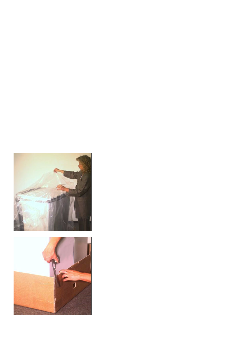
1. Removing the plastic foil
Remove the plastic foil that surrounds
the scanner.
2. Cutting open the box
Cut open the four lower corners of the
cardboard box.
1– 2 Edition September 2000
ABC
Unpacking and Installing
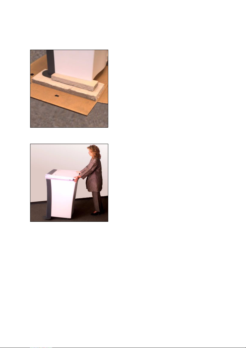
3. Removing parts of the box
Remove all cardboard box parts under
the scanner. A second person is required to slightly raise the scanner for this
purpose.
4. Pushing the scanner to the installation
site
Push or pull the scanner to the site
where it will be taken into operation.
However, allow approx. 1 m gap to the
wall as cables still need to be connected
later and the back panel must be screwed on and off.
Nexscan F 4100/F 4200 – Operation 1– 3

Unpacking and Installing
Note: Take the length of the SCSI cable
between scanner and computer into
2
account when positioning the scanner.
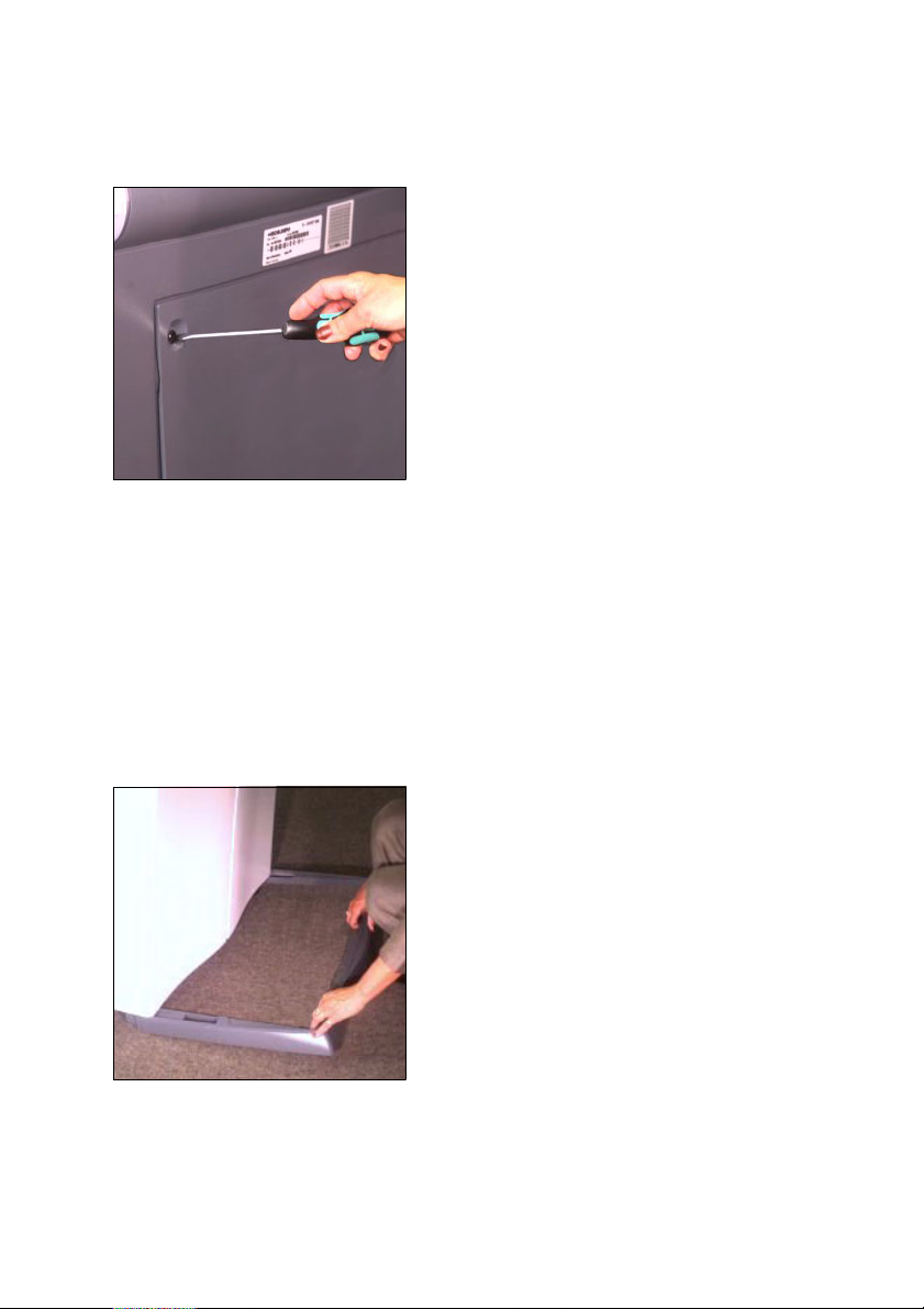
5. Removing the back panel
Unscrew the four screws at the back of
the device with a flat screwdriver and
remove the back panel.
You will need the CD with the ICC profiles, which is attached to the back panel,
later on when installing the software.
Attention: When loosening transport
1
safety devices: Work carefully!
0
Ensure that you do not support yourself on the fluorescent tubes in the bottom of the device and that no parts fall
onto the fluorescent tubes.
0
Do not touch the stray light foil above
in the scanner.
ABC
Note: All transport safety devices to be
removed are identified with a red mar-
2
king (adhesive label).
1– 4 Edition September 2000
ABC
Unpacking and Installing
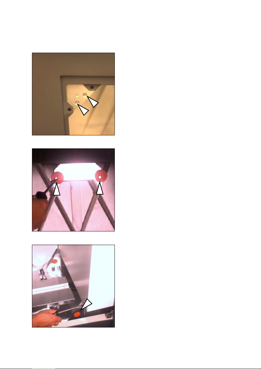
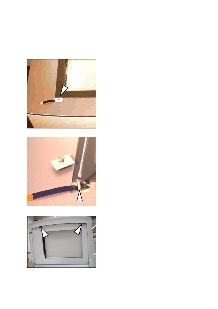
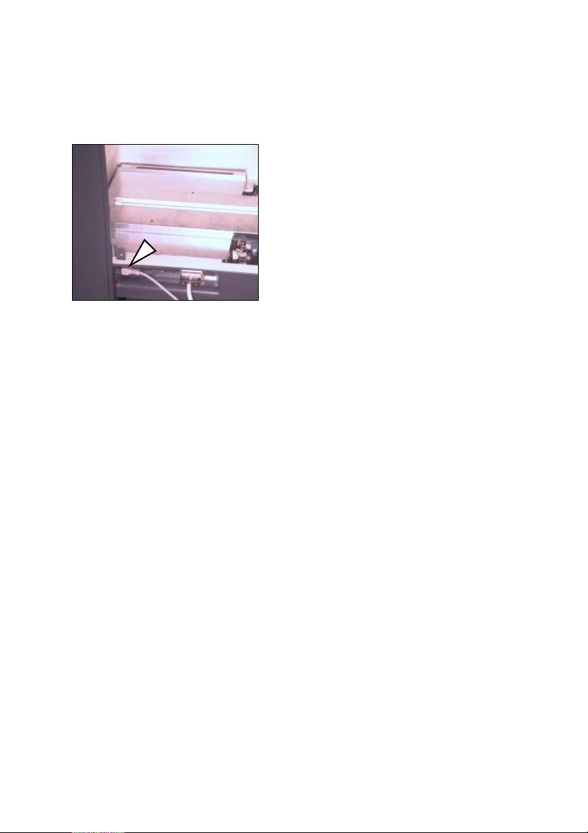
6. At the rear in the device, use a flat
screwdriver to remove the 2 vertical
slotted screws (not the double seams
screws!) to the upper left in the back
panel cutout.
7. Remove the 2 screws at the front, inside
the device, connecting the device housing and the scanning unit (accessible
from the rear only).
8. Removing the shipping restraint brakket
Unscrew the three screws on the shipping restraint at the back of the device
and remove it.
Nexscan F 4100/F 4200 – Operation 1– 5
Unpacking and Installing
ABC
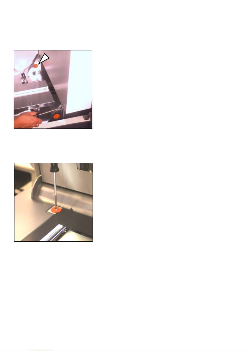
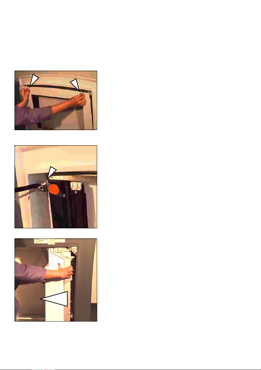
9. Removing the shipping restraint brakket
A similar safeguard must now be removed at the front of the device. The three
screws must be unscrewed in the same
fashion.
10. Open the scanner lid
11. Remove the air-cushion foil and the silk
paper
12. Removing the transport safety washer
Remove the slotted screw with a flat
screwdriver and remove the transport
safety washer.
Replace the screw and use it to secure
the clamp.
1– 6 Edition September 2000
ABC
Unpacking and Installing
13. Unscrewing the shipping restraint
screw
0
Unscrew the screw on the clamp element for the front left glass plate with
a flat screwdriver. Remove the clamp
element.
0
Unscrew and remove the now visible
screw.
0
Replace the clamp element and fasten
it with the screw. Ensure that you
have inserted the clamp element the
right way round so that the glass pane
does not break.
14. Removing the clamping pads
Remove the two clamping pads for the
knurled screws.
Nexscan F 4100/F 4200 – Operation 1– 7
Unpacking and Installing
ABC
15. Removing the bracket for transparency
scanning
0
Remove the two knurled screws in the
scanner lid and carefully remove the
plate with the glass pane.
0
Remove the bracket for the transparency scanning by unscrewing the
screw with a flat screwdriver. Ensure
that the bracket does not fall onto the
glass plate for the scanner lid unit.
0
Screw the plate back into the
scanner lid.
16. Move the camera carriage to the left
carefully and slowly push the camera
carriage from right to left into the back
of the device by hand.
1– 8 Edition September 2000
ABC
Unpacking and Installing
Attention: Do not touch the stray light
1
2
foil above.
Note: The camera carriage can not be
pushed back again by hand. It must/can
be left in this position. The software will
move the carriage back to its required
position.
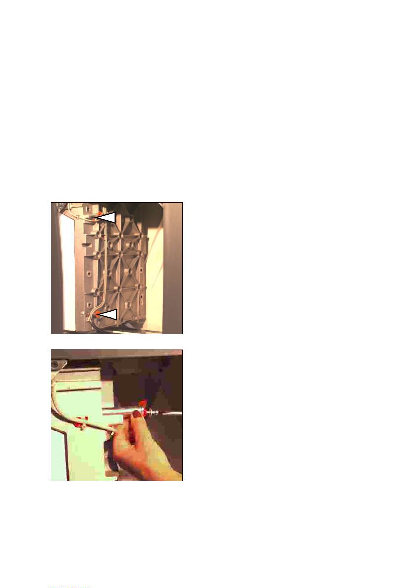
17. Removing the restraining pins
Remove the screws on the shipping restraints with a flat screwdriver.
Now pull out the long screws and the
pins.
Nexscan F 4100/F 4200 – Operation 1– 9
Unpacking and Installing
ABC
18. At the rear in the device, use a flat
screwdriver to remove the 2 vertical
slotted screws (not the double seams
screws!) to the upper right in the back
panel cutout (already carried out on the
left-hand side).
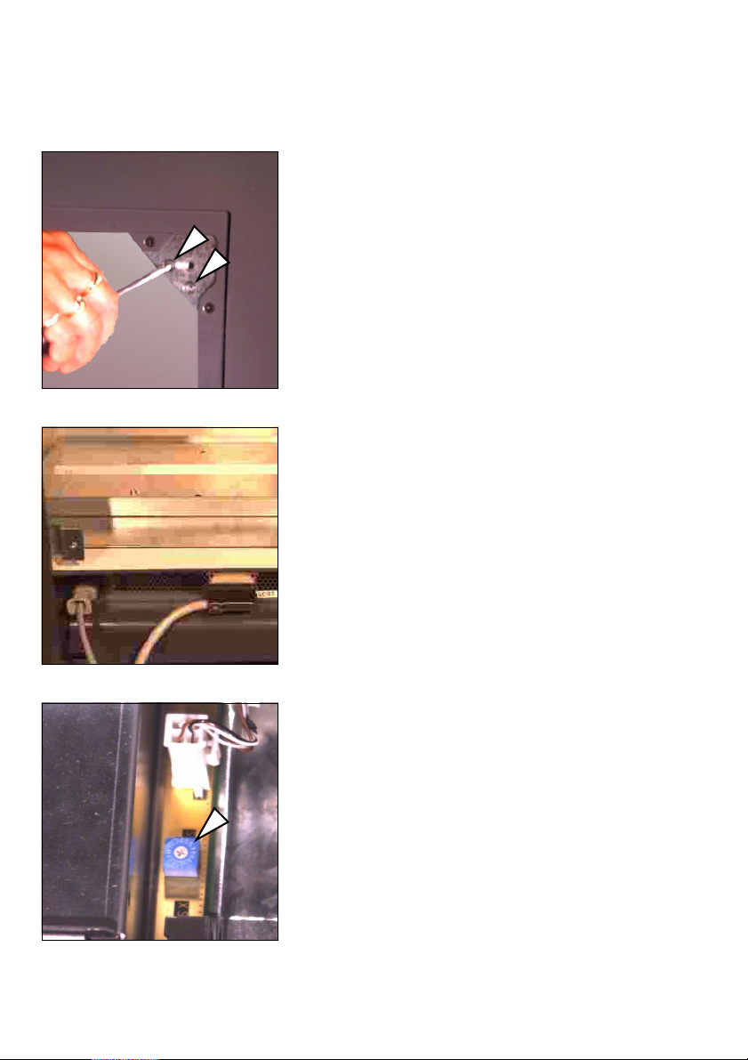
19. Connect the power cable and the SCSI
cable to the lower back of the device.
20. Setting the SCSI address
Set the correct SCSI address at the
lower back in the device. On delivery,
the scanner is set to SCSI address number 5. If this address is occupied, select
another number between 1 and 7.
Please note that if an internal CD-ROMdrive is connected in the computer,
address 3 can be used for this device. To
enter the setting you need a small flat
screwdriver.
1– 10 Edition September 2000
ABC
Unpacking and Installing
21. Closing the back panel
Close the back panel again. Slide the
back panel into the two slits below and
fasten the 4 screws at the rear of the
device.
Make sure you have removed the CD
with the ICC profiles, which is attached
to the back panel, and that the cables
are laid in the back panel cutout and
not jammed anywhere.
22. Final placement of the scanner
Now place the scanner in its final position on a secure and level surface.
23. Setting the height
If the scanner is not steady, you can
adjust the height of the front left and
right-hand feet. For this purpose, loosen the slotted screw from the outside –
one turn is sufficient – and you can
adjust the foot and secure it again.
24. Removing the base aperture
Slide the base aperture from the front
under the device until it engages. The
end clips for the aperture must penetrate into the rear covering.
Nexscan F 4100/F 4200 – Operation 1– 11

Unpacking and Installing
2
1
ABC
Note: Keep all transport safety devices
in a safe place so that they can be reused if the device needs to be transported again.
Attention: Transportation without
transport safety devices can cause
damage to the device.
1– 12 Edition September 2000

ABC
2 Connecting
Installation
After you have unpacked and moved your
Nexscan F 4100/F 4200 to its intended position, it
must be installed.
The following steps are required:
0
Connecting the Nexscan F 4100/F 4200 to the
workstation.
0
Connecting the Nexscan F 4100/F 4200 to the
power supply.
0
Switching on the Nexscan F 4100/F 4200.
0
Installing the software.
0
Install the calibration data.
Note: Any additional information on installation
can be obtained via the following Internet
2
address: http://www.heidelberg.com/
Connecting
Connecting the Nexscan F 4100/F 4200 to the workstation
Warning: The connection cable must be attached
in a voltage-free state. Only connect the power
33
1
Nexscan F 4100/F 4200 – Operation 2– 1
cables after connecting the connection cables.
This protects you against fatal electric shocks in
the case of a short circuit on one of the devices
and it protects the electronics system against
failure caused by voltage impulses during
potential differences.
Attention: Screened data cables with screened
plugs must be used, to adhere to radio
interference suppression regulations. Only use
connection cables and adapters approved by
Heidelberg.

Connecting
Observe the length
of the SCSI cable!
ABC
The Nexscan F 4100/F 4200 has an SCSI
connection. You should always fit an SCSI
interface card to your computer, to which only
the scanner is connected. Commands which are
sent from the workstation to the Nexscan F 4100/
F 4200 and image data which is transferred from
the Nexscan F 4100/F 4200 to the workstation
pass through this link. The Nexscan F 4100/
F 4200 can be connected to any other SCSI device,
which has an SCSI connection, by means of the
connection cable – observe the length of the
cable when setting up the system.
Connect the SCSI cable for the Nexscan F 4100/
F 4200 to the SCSI port of your computer.
If, in addition to the Nexscan F 4100/F 4200 and
the operating unit, other SCSI devices are
connected to the SCSI bus, the Nexscan F 4100/
F 4200 must always be the last link in the chain,
as the SCSI bus in the Nexscan F 4100/F 4200 has
a terminator.
The SCSI bus must not exceed a total length of
6 m, otherwise you may encounter operational
difficulties.
2– 2 Edition September 2000
ABC
3
3
Connecting the Nexscan F 4100/F 4200 to the power supply
Note: The device is switched off
at both poles with the isolator
2
switch and is then deenergized, except for the
power cable connection up to
the switch.
Connect the device to the power supply
by means of the three-pin plug and
socket included in the delivery. The
device may only be operated when a
grounded conductor is connected.
Warning: Never plug in or remove the power cable
with wet hands and only ever get hold of it at the
plug. A damaged power cable can cause leakage
current and electric shocks. Protect the power
cable against damage. Never place any heavy
objects upon it and never squash it.
The electrical outlet is located on the rear of the
device underneath the service flap.
Connecting
The device automatically adapts itself for differing
voltage levels. These values are displayed on the
sticker on the rear of the device.
The operator has no access to the fuse.
Warning: The device may only be repaired by
Service personnel.
Do not install the device in the vicinity of airconditioning systems and protect it from moisture
and direct sunlight.Attention:
1
Nexscan F 4100/F 4200 – Operation 2– 3

Connecting
ABC
Attention:
Unauthorized opening of the device's housing not
expressly described in the documentation and
improper repairs can lead to considerable danger
for the user.
Servicing work may only be performed by
authorized specialist personnel.
The respective accident prevention regulations
must be observed at all times.
Non-observance of accident prevention
regulations can lead to the loss of accident
insurance cover.
Use one of the power cables provided, appropriate
to the supply available, to connect the device to
the power supply. The local national regulations
must be observed when connecting the device
using power cables, which were not provided by
Heidelberg Prepress or when using connector
adapters.
Cable types used in USA and Canada must
correspond to the type SJT or better.
Attention:
1
2– 4 Edition September 2000
Taking national requirements into consideration,
select a cable from the table below if you want to
connect 100 V - 127 V or 200 V - 240 V AC.
Service personnel ensure the use of nationally
recognized power plugs in compliance with the
grounded conductor connection.
Notes regarding the power cable:
 Loading...