

Page 1
User Guide
MLA150
Maskless Aligner
Page 2

MLA150
ii User Guide
Doc. No.: DWL-HI-062
Revision: 1 (July 2016)
Copyright © 2016 by Heidelberg Instruments
Page 3

MLA150
Table of Contents
User Guide i
Table of Contents
Table of Contents ........................................................................................................... i
List of Figures ............................................................................................................... iv
List of Tables ................................................................................................................ iv
1 Introduction ........................................................................................................... 1
1.1 About this User Guide ............................................................................................. 1
1.2 Contact .................................................................................................................... 2
1.3 Related Documentation ........................................................................................... 3
2 Safety ..................................................................................................................... 5
2.1 Intended Use and Limitations .................................................................................. 5
2.2 Conventions ............................................................................................................ 6
2.3 Laser Safety ............................................................................................................ 6
2.4 Electrical Safety ...................................................................................................... 8
2.5 Other Risks during Operation .................................................................................. 9
2.6 Interlock .................................................................................................................. 9
2.7 Labels ................................................................................................................... 10
3 System Description ............................................................................................. 13
3.1 Lithography Main Unit ........................................................................................... 14
3.1.1 Flowbox ................................................................................................... 14
3.1.2 System Components ............................................................................... 17
3.1.3 Optics System ......................................................................................... 20
3.2 Electronics Rack ................................................................................................... 22
3.3 Orientation of Stage and Design ........................................................................... 23
4 Wizard Description .............................................................................................. 25
4.1 Overview: Exposure Wizard .................................................................................. 25
4.2 Static Wizard Elements ......................................................................................... 27
Page 4

MLA150
Table of Contents
ii User Guide
4.2.1 Menu Bar ................................................................................................. 27
4.2.2 Tab Section .............................................................................................. 27
4.2.3 Info Section .............................................................................................. 28
4.3 Substrate Representation ...................................................................................... 31
5 System Startup .................................................................................................... 33
5.1 Powering Up .......................................................................................................... 33
5.2 Powering Down ................................................................................................ ..... 34
6 Job Setup ............................................................................................................. 35
6.1 Select Job .............................................................................................................. 36
6.2 Select Substrate Template .................................................................................... 37
6.3 Load Design .......................................................................................................... 38
6.3.1 Standard: First Exposure ................................................................ ......... 38
6.3.2 Standard: Alignment ................................................................................ 39
6.3.3 Series ....................................................................................................... 40
6.4 Convert Design ...................................................................................................... 41
6.5 Load Substrate ................................................................................................ ...... 43
6.6 Draw Structures ..................................................................................................... 46
6.6.1 Draw Image ............................................................................................. 47
6.6.2 Draw Line or Polygon ............................................................................... 48
6.6.3 Expose Crosses in Draw Mode ................................................................ 49
6.7 Setup Overlay Alignment ....................................................................................... 50
6.8 Expose Design ...................................................................................................... 54
6.8.1 First Exposure Procedure ................................ ................................ ........ 54
6.8.2 Overlay Exposure Procedure ................................................................... 55
6.8.3 Series Exposure Procedure ..................................................................... 57
6.8.4 Draw Mode Exposure Procedure ............................................................. 59
6.9 Unload Substrate ................................................................................................... 60
7 System Utilities and Tools .................................................................................. 63
Page 5

MLA150
Table of Contents
User Guide iii
7.1 Control Panel ........................................................................................................ 63
7.2 Camera Window .................................................................................................... 65
7.3 Optimizing Alignment and Exposure Results ........................................................ 66
7.3.1 Unsatisfying Alignment Measurements .................................................... 66
7.3.2 Unsatisfying Exposure Results ................................................................ 67
7.4 Back Side Alignment ............................................................................................. 68
7.4.1 Overview of BSA Marker Zones .............................................................. 68
7.4.2 BSA Exposure Preparation ...................................................................... 70
8 Operator Maintenance and Troubleshooting .................................................... 71
8.1 Operator Maintenance .......................................................................................... 71
8.2 Troubleshooting .................................................................................................... 72
8.3 TeamViewer Software ........................................................................................... 73
Page 6

MLA150
List of Figures
iv User Guide
List of Figures
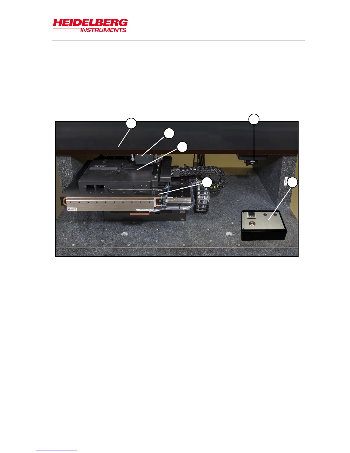
Figure 1: System components .............................................................................. 13
Figure 2: Elements of the laminar flow box ........................................................... 15
Figure 3: Temperature control readout ................................................................. 15
Figure 4: System support ................................ ...................................................... 17
Figure 5: Operator Panel ...................................................................................... 17
Figure 6: Stage system with optics plane .............................................................. 19
Figure 7: Interferometer function ........................................................................... 21
Figure 8: E-rack components ................................................................................ 22
Figure 9: Orientation of stage and design ............................................................. 23
Figure 10: Machine-related design rotation ........................................................... 23
Figure 11: Rotation of coordinate system on chuck .............................................. 24
Figure 12: Location of coordinate pairs ................................................................. 24
Figure 13: Wizard window overview ..................................................................... 25
Figure 14: Unloading options in Standard Mode and Series Mode ....................... 60
Figure 15: Camera window ................................................................................... 65
Figure 16: BSA marker zones overview ................................................................ 69
Figure 17: Orientation on wafer for BSA ............................................................... 70
List of Tables
Table 1: Field of view (top side, back side) ........................................................... 20
Page 7

MLA150
1 Introduction
User Guide 1
The MLA150 is a high speed direct write lithography tool extended by capabilities
formerly only available on Mask Aligners. It can expose the patterns directly without
prior fabrication of a mask resulting in a significantly shorter prototyping cycle. It offers
topside alignment and backside alignment with high accuracy, and a light source which
generates sufficient dose to expose even thick and less sensitive resists. The MLA150
allows using substrates of any size and shape and provides flexible change of pattern,
distortion compensation and other software corrections. The system can produce
structures down to 1 µm. The alignment accuracy can be as good as 250 nm under
optimized conditions.
1.1 About this User Guide
This user guide gives information and instructions on how to handle the MLA150 system
properly. It is important that every person who intends to work with the system reads
this guide in order to avoid possible mishandling leading to damage to the system or to
persons. Therefore, by all means, read the safety instructions carefully before starting
work with the system. The guide assists the user in performing the exposure procedure
beginning at system startup and ending with the exposure procedure itself. The
subchapters in 6 Job Setup build a sequence of tasks that have to be executed in order
to prepare the exposure job.
Additionally, you find a description of the system and of the Exposure Wizard. Also
information about system utilities and troubleshooting are given in the final chapters.
Technical data can be found in the related document Technical Data Sheet
To facilitate following the instructions and information, a list of conventions indicating the
type of information is given here.
Note:
Indicates that additional information or advice follow to get best results.
1.
Signalizes that this is the first step of a step-by-step instruction followed by
further steps
Indicates a result which the user can see or hear. It can also just be an
intermediate result and can therefore be followed by further steps of the same
instruction.
Indicates that the following information or instruction is an alternative step e. g.,
to abort a process or to be referred to another instruction or chapter.
This symbol is used to mark a location in a figure that is related to the
instruction. The numbers in the symbol correspond to the number of the step in
the instructions.
i
1
Page 8
MLA150
1 Introduction
2 User Guide
1.2 Contact
Should you need assistance, please contact your local service office:
You can also reach Heidelberg Instruments via email: himt@himt.de, or visit our site on
the internet: http://www.himt.de
China:
Europe:
Heidelberg Instruments Service China
Rm.101, Block 1, Animation Park,
Yuehai Street, Nanhai Road,
Nanshan Distr., Shenzhen 518045
China
Phone:+86-755-8301599-1 / -2 / -7
Fax: +86-755-8301599-4
Email: service_china@himt.de
Heidelberg Instruments GmbH
Service Department
Tullastraße 2
69126 Heidelberg
Germany
Phone: +49-6221-3430-0
Fax: +49-6221-3430-30
Email: service_europa@himt.de
Japan:
Korea:
Heidelberg Instruments Service Japan
Germany Center for Industry & Trade
1-18-2, Hakusan
Midori-ku, Yokohama, 226-0006
Japan
Phone:+81-45-938-5250
Fax: +81-45-938-5251
Email: service_japan@himt.de
Heidelberg Instruments Service Korea
#316 Expo Officetel, 381
Mannyeon-dong, Seo-gu
Deajeon, 35203
South Korea
Phone:+82-42-482-1668
Fax: +82-42-482-1669
Email: service_korea@himt.de
Taiwan:
USA:
Heidelberg Instruments Service Taiwan
6F-5, No. 192 DongGuang Road
Hsinchu City, 30069
Taiwan
Phone +886-3-5715188
Fax +886-3-5715388
E-Mail: service_taiwan@himt.de
Heidelberg Instruments Inc. USA
2807 Oregon Court, Unit E2
Torrance, CA, 90503
USA
Phone:+1-310-212-5071
Fax: +1-310-212-5254
Email: service_usa@himt.de
Page 9

MLA150
1 Introduction
User Guide 3
1.3 Related Documentation
Heidelberg Instruments offers several further manuals related to the machine and its
operation. If you did not get one of these or need an update, please contact Heidelberg
Instruments, Germany (1.2 Contact). See the list of related documents below:
Pre-Installation Guide
Environmental and electrical
requirements, sizes and weights of
components etc.
PI- Site Inspection checklist
Checklist containing questions regarding
the conditions of the costumer’s
installation site for the system.
Safety guide
Describes necessary safety measures
during move-in, installation as well as
servicing and maintenance times.
Conversion Software Manual
Manual for the HIMT conversion software
used for data preparation and fractioning.
Design Guide
Instructions on design rules and design
creation.
Maintenance Guide
Guide for Maintenance and
Troubleshooting, as well as an overview of
typical service tasks.
Technical Data Sheet
Overview of the systems technical data.
Quick Guide
Short instructions to execute an exposure.
Page 10

MLA150
1 Introduction
4 User Guide
Page 11

MLA150
2 Safety
User Guide 5
The MLA150 protects operators from exposure to laser radiation, dangerous voltages or
moving parts while operating the equipment. All moving parts, lasers and their
associated optics are enclosed within a flow box. During operation, opening the flow box
window will immediately stop any exposure or measurement process.
Still, it is vital that the operators and all other persons who are allowed access to the
system have been informed about any remaining risks.
2.1 Intended Use and Limitations
The intended use of the MLA150 lithography system is to expose structures on
photosensitive, non-flammable layers which are located on non-flammable substrates.
These substrates must not exceed the specified maximum dimensions and must be free
of damage such as scratches or cracks.
The MLA150 is intended only for professional use. The related user documentation is
part of the product, and the user is under the obligation to read the documentation
before using the product.
Every other purpose of use than that stated in this section is prohibited. In case of
damage by using the product outside this stated purpose, no liability is assumed by the
Heidelberg Instruments Mikrotechnik GmbH.
In addition to the intended use stated above, the following purposes of use are
prohibited and defined as misuse:
Operation outside the operating data stated in the data sheet or in the sales
confirmation.
Operation with materials other than the approved materials.
Change of the factory settings by unauthorized persons.
Use of attachment parts other than Heidelberg Instruments components.
Operation of the system in a potentially explosive environment or aggressive
atmosphere.
No untrained person, or person not familiar with the contents of the following sections
is allowed to operate the system or work in its close environment. If instructions are not
followed carefully, danger to personal health and damage to the equipment is at risk.
At all times, follow all warnings and instructions given in this manual, the system
software, safety labels on the system, or by our engineers.
Page 12
MLA150
2 Safety
6 User Guide
2.2 Conventions
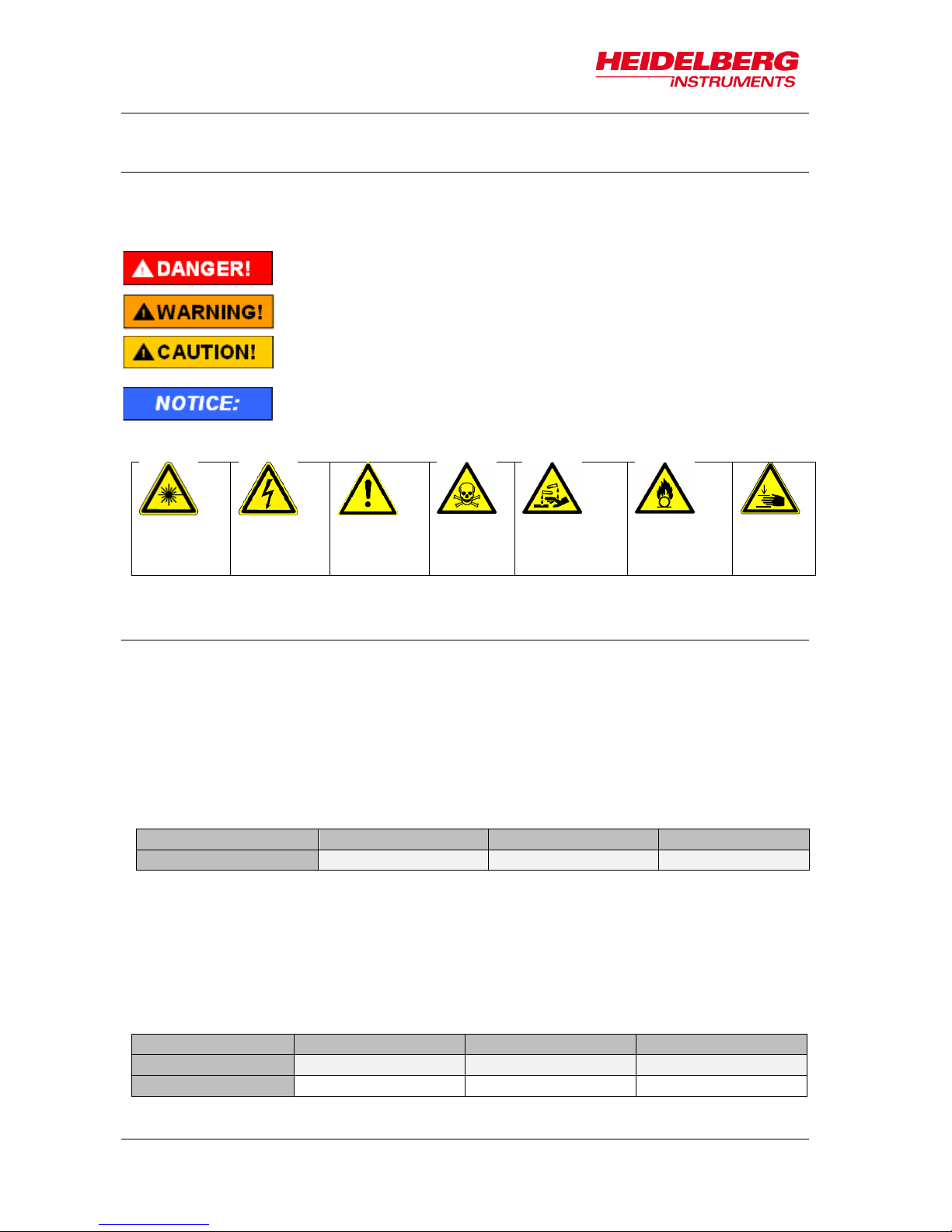
Throughout this manual there are safety warnings. To classify the degree of danger in
each of these situations, this guide uses the conventions defined in ANSI Z535.6-2011:
Laser
beam
hazard
Electrical
shock
hazard
General
warning
Toxic
hazard
Corrosive
material
hazard
Flammable
material
hazard
Pinch
point
hazard
2.3 Laser Safety
The MLA150 employs two types of continuous wave lasers, one for position
measurement of the stage (interferometer laser), one for design exposure (exposure
laser). When the window is closed, all laser light is blocked or absorbed, and the system
is effectively of laser class 1.
When the window is opened for loading or unloading, the interferometer laser beam is
accessible. Under this condition, the system has the same laser class as the
interferometer laser in use, which is laser class 2.
Laser Type
Wavelength (nm)
Power (mW)
Laser Class
HeNe
632
< 6
2
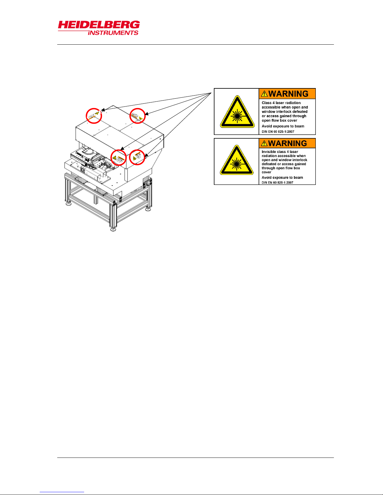
The exposure laser beam is a powerful beam that is usually covered completely by
optics covers. Power and wavelength of the exposure laser depend on the specific
configuration, but the exposure laser beam is always dangerous for the eye, sometimes
also for the skin. Even reflected light may be dangerous.
If the optics covers are opened, the accessible energy is of the class 4 category
(DIN EN-60825-1).
Danger indicates a hazardous situation, which, if not avoided, will
result in death or serious injury.
Warning indicates a hazardous situation, which, if not avoided,
could result in death or serious injury.
Caution indicates a hazardous situation, which, if not avoided,
may result in minor or moderate injury.
Denotes warnings against possible misuse that can lead to
machine damage.
Laser Type
Wavelength (nm)
Power (mW)
Laser Class
Diode, blue
405
≤ 10000
4
Diode, UV
375
≤ 3000
4
Page 13

MLA150
2 Safety
User Guide 7
If conditions require the opening of the optics covers, such as for servicing or
troubleshooting by trained service personnel, then personnel must observe all
precautions required for a laser of above mentioned class in the whole area surrounding
the MLA150.
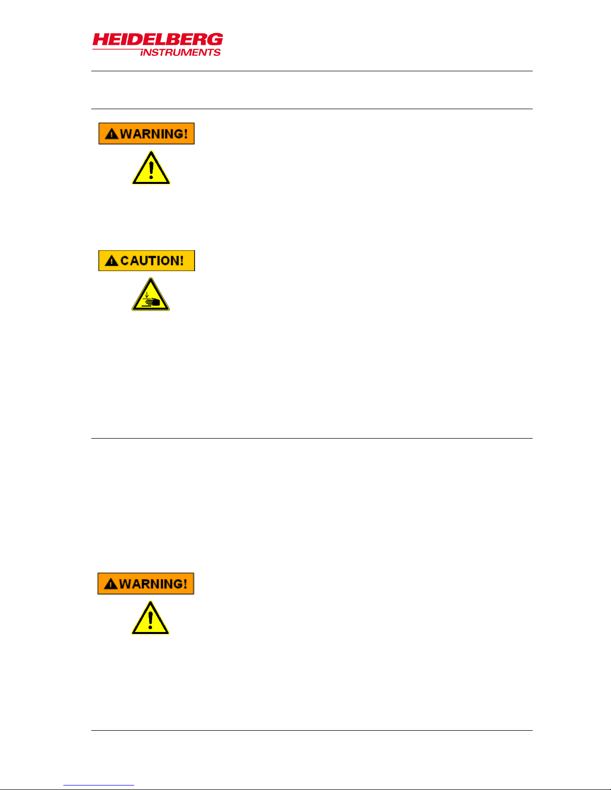
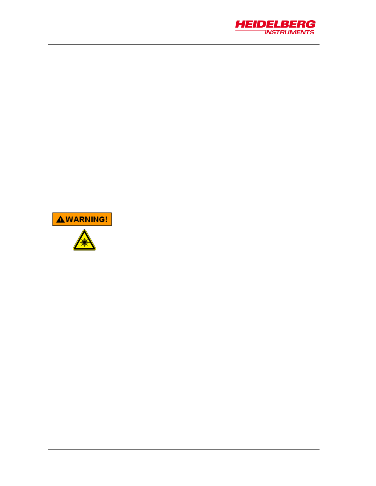
Eye injuries and/or skin burns!
Severe damage to the eye and possibly to the skin can be
caused by laser radiation of class 3B or 4
Avoid possible direct or indirect exposure of eyes or skin to
laser radiation at all times.
Do not operate the system with open optics cover if not acting
under explicit instruction of an HIMT service engineer.
Do not enter any area cordoned off by HIMT service
engineers during adjustment work.
Do not put anything reflective or flammable into the beam
path.
If the system has to be operated with open optics cover e.g., for
trouble shooting:
Cordon off the area and place warning signs.
Wear appropriate safety goggles. Note that these cannot
protect long against a direct beam, but are only meant as
protection against stray light! Also keep in mind that you
cannot see the laser beam with goggles on, so the risk of skin
burns increases.
Use the lowest possible laser power or reduce the power as
far as possible with filters.
Never leave the laser on when unattended. Make sure only
qualified personnel may switch on the laser in such a
machine state.
Do not place reflective objects in, or near the laser beam path.
Laser light scattered by reflective objects can be as damaging
as the original beam. Objects such as rings, watchbands,
and metal pens or pencils can be hazardous.
Page 14

MLA150
2 Safety
8 User Guide
2.4 Electrical Safety
A CEE type 220-240 V, 16 A single-phase cable connector supplies operating power in
the MLA. It is also possible to attach a local-type cable to a local-type wall connector.
Please refer to the Pre-Installation Guide for details.
Electrical Shock!
Fatal electrical shock and/or severe burns can be caused by the
supply voltage of up to 240VAC 16A for the system, and up to
420VAC 32A for certain laser types.
Never use the equipment if cables or plugs have been
damaged.
Plug the MLA and its components only into approved outlets
with correct ground. Power requirements are described in the
Pre-Installation Guide.
Ensure that both the voltage and frequency of a power source
match the voltage and frequency stated on the equipment’s
electrical label.
Not all power cords have the same current ratings.
Household extension cords do not have overload protection
and are not meant for use with sensitive electronic
equipment. Never use household extension cords for any
component of the MLA.
Always follow the five safety steps if equipment containing
electrical circuits with voltages >50VAC has to be opened:
disconnect, apply restart lockout, check if equipment is deenergized, ground / short circuit equipment, cover
neighboring elements that are still energized
If access to the interior of any electronics component is
necessary while system is in operation, exercise extreme
caution. Only qualified service personnel may have access to
the interior.
Page 15
MLA150
2 Safety
User Guide 9
2.5 Other Risks during Operation
Injuries by moving parts or heat!
If covers are removed, the operator may be exposed to
dangerous collisions with moving parts, or heated components.
Do not remove any covers that are fixed with screws
Heed the warnings if removing any other covers
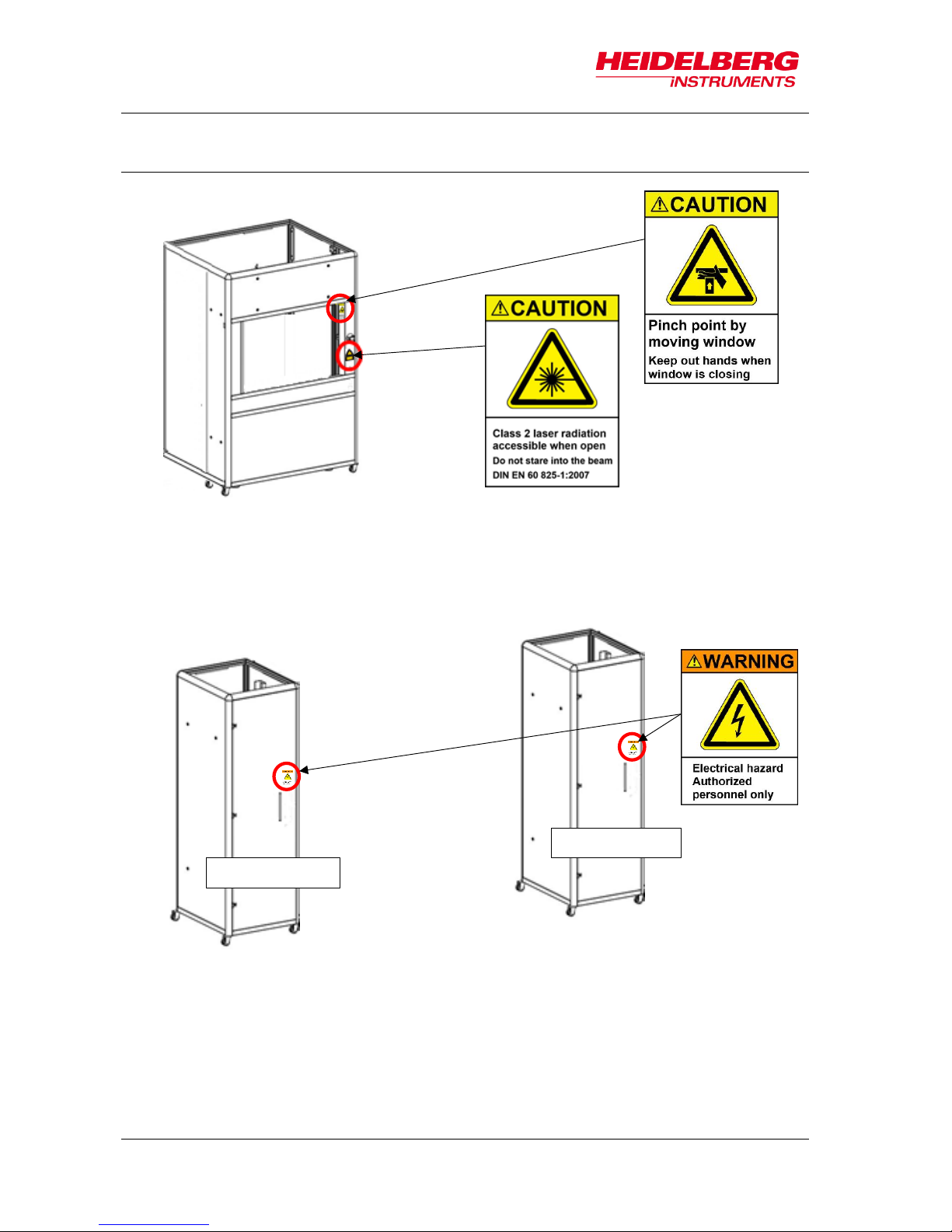
Pinch risk by closing window!
Mild pinch injuries are possible if fingers are brought between
the upper window frame and the window while the window
closes. The loading window is driven pneumatically with low
pressure. It does not have enough force to injure a body or
limb, but skin may be pinched.
Don not close the window while resting a hand at the upper
frame or upper window edge.
Do not put a hand through the already closing window.
2.6 Interlock
To protect the operator from hazards by laser light or moving stage, interlock circuits
prevent stage movement and access to laser light as soon as the window opens. A
safety switch stops the stage, holding it in position, and closes the laser shutter. If an
exposure has been running at that moment, the result is irreversibly lost.
The stage interlock can be overridden by service engineers by a key switch for
servicing, together with a confirmation from the menu. While this service mode is
activated, the main bar and background of the Exposure Wizard turns red.
Injuries by moving parts or laser light!
While the system is in service mode, dangerous levels of laser
light are accessible, and the stage can move with window open.
Only HIMT service engineers are allowed to put the machine into
service mode.
During servicing or maintenance by service engineers, heed
the warnings given in the Safety Guide.
If service mode was left active accidentally, switch back to safe
mode and remove the key. Return it to the service local office.
Page 16
MLA150
2 Safety
10 User Guide
2.7 Labels
Flowbox front
E-Rack
REAR DOOR
FRONT DOOR
Page 17
MLA150
2 Safety
User Guide 11
Optics cover:
front cover, side covers, rear cover
Page 18

MLA150
2 Safety
12 User Guide
Page 19
MLA150
3 System Description
User Guide 13
This chapter gives a short description of the MLA150 lithography system. The MLA150
system consists of the following individual components:
Lithography Unit
Electronics Rack
Cooling water supply (not explicitly described in this document)
Operator workstation
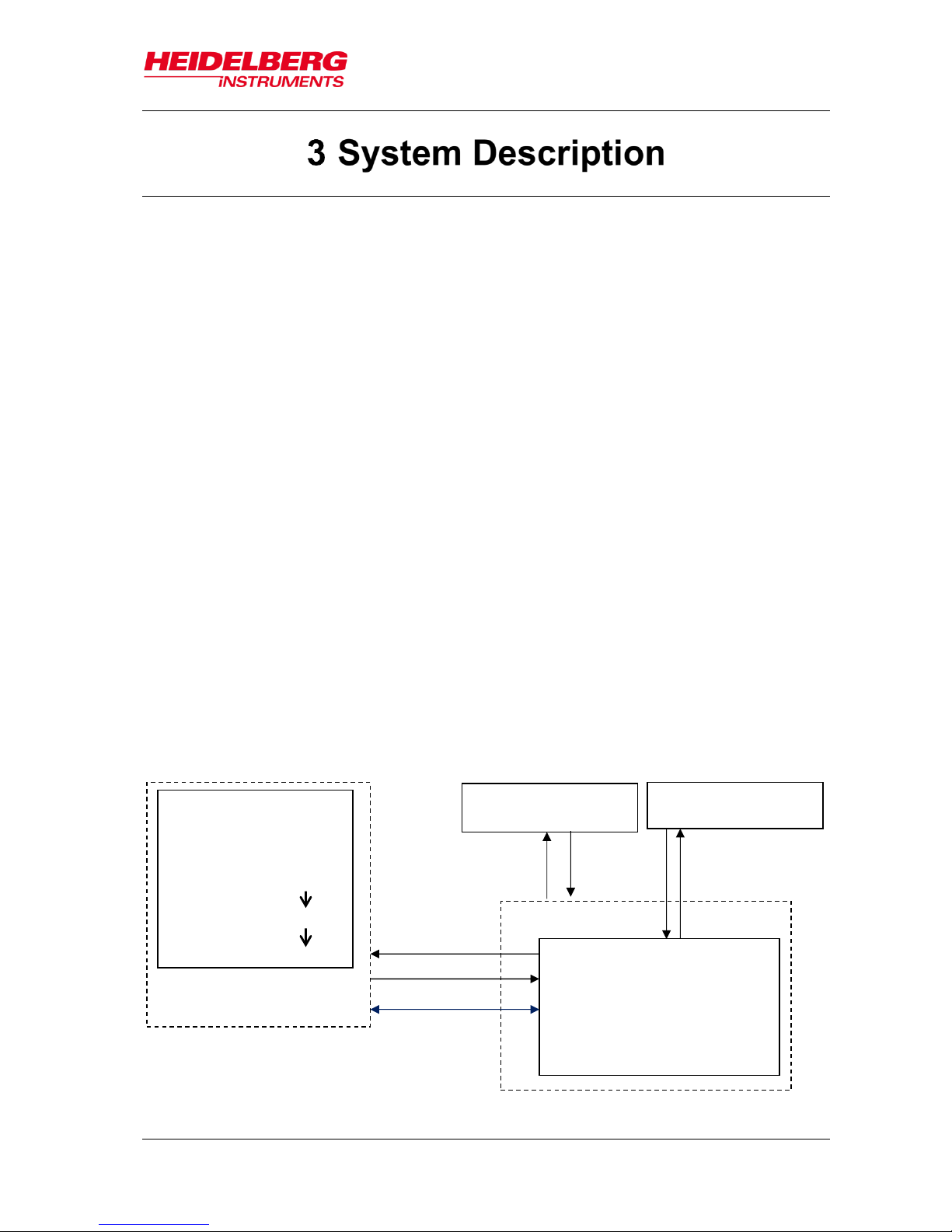
The main principle of the functional interaction between the system components is as
follows:
A workstation comprising two computer monitors, a keyboard, a mouse and the User
PC, that is located inside the electronics rack, represents the interface between user
and system. The user controls the system via our graphical user interface on the User
PC. This data is processed by the components located inside the electronics rack such
as the stage controller which communicates with the stage and controls its movement
based on the feedback given by interferometers that are placed in the main unit.
The system has two cooling water supply units, called chillers. One of them makes sure
that the system runs in a stable environment in terms of temperature. The other one
serves as cooling unit for the laser and the motors.
USER PC
design positioning
alignment sequences
system parameters
conversion: CAD design
conversion
exposure data
MLA
Main Unit
Flow Box
sensors
control
cooling water supply
for Flow Box
cooling water supply
for Main Unit
ELECTRONICS RACK
data
Figure 1: System components
Page 20
MLA150
3 System Description
14 User Guide
3.1 Lithography Main Unit
The Main Unit comprises the following elements:
Flow box
Granite Construction
Optics System
3.1.1 FLOWBOX
The flow box is the housing of the lithography system and protects the MLA150 from
damage. It also provides a stable environment in terms of temperature, laminar flow and
clean air. This is of importance because only such a stable environment guarantees
constant exposure conditions which guarantees the smallest possible variation of
exposure parameters. The covers of the flow box are removable, but only for service
purposes.
Injuries by moving parts or laser light!
Severe damage to the eye and possibly to the skin can be
caused by laser radiation of class 3B or 4
Do not open the covers of the flow box.
Flow box covers may be opened only by, or under direct
instruction from, experienced service personnel!
Page 21
MLA150
3 System Description
User Guide 15
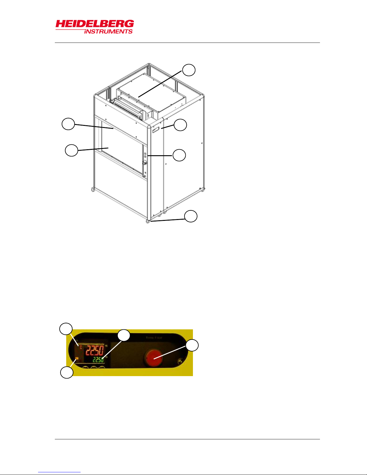
ELEMENTS OF THE LAMINAR FLOW BOX:
TEMPERATURE CONTROL UNIT
The flow box is temperature controlled by means of regulated heating of the
incoming air. The air is cooled down by the water-cooling unit and then reheated to
1
TEMPERATURE CONTROL UNIT
2
DISPLAY
3
SWITCH PANEL
4
CASTOR WHEEL
5
WINDOW
6
LIGHT
1
ACTUAL TEMPERATURE
2
TARGET TEMPERATURE
3
RESET BUTTON
4
HEAT OUTPUT REGULATOR
Figure 2: Elements of the laminar flow box
1
2 3 4
5
6
Figure 3: Temperature control readout
1
2
3
4
Page 22
MLA150
3 System Description
16 User Guide
the required process temperature. The temperature control unit is located within the
top compartment and has a display readout accessible from the outside through a
hole in the flow box cover. In case the temperature exceeds +65°C inside the flow
box, which can be caused by a malfunction of the fan, the control unit shuts down
the heating system. The push button switch turns red. The heating system can be
reset by pushing the button once but this should only be done if the reason for the
failure is known. The display readout has a small icon in the left, blinking in regular
intervals. This icon shows the activity of the heat output regulator. If the icon blinks
periodically then the heat regulation works properly. If the icon is illuminated or not
illuminated without any periodical change, then the temperature control unit is not
working trouble-free anymore. It is recommended to shut down the system and call
one of Heidelberg Instruments service offices (see 1.2 Contact).
CASTOR WHEELS
The flow box stands on eight castor wheels that have locking brakes in order to
provide a stable position. These castor wheels are not height-adjustable. The
machine is leveled by adjusting the four feet.
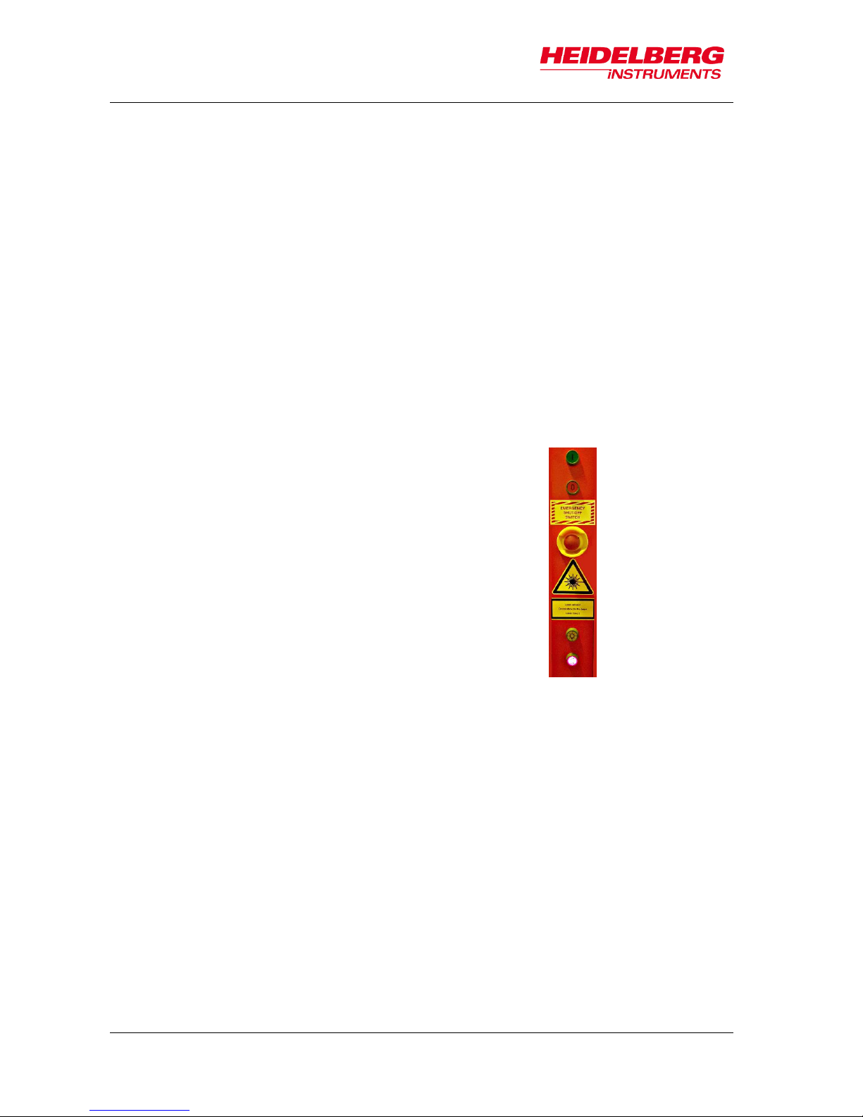
SWITCH PANEL
At the front side of the flow box several buttons are
located. The green button is used for powering up the
system, the red one is for powering it down. The
button in the middle is the emergency off button. For
opening and closing the window, the push button is
used. The flow box provides a light source for inside,
which is, depending on the application, yellow or red
light. The light switch is located between the
emergency off button and the window push button.
WINDOW
The window is opened only for loading and unloading purposes. During operation,
the window cannot be opened for safety reasons. The push button at the front of the
flow box opens and closes the window by means of compressed air. This button is
disabled while an exposure is running.
On (I)
Off (0)
Emergency Off
Window push button
Light push button
Page 23
MLA150
3 System Description
User Guide 17
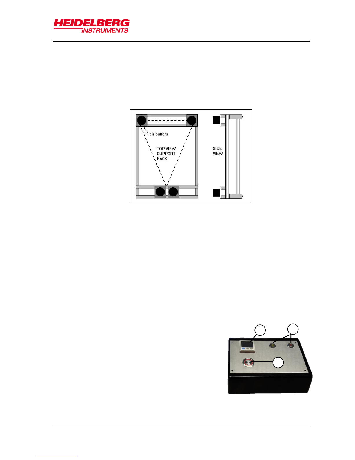
3.1.2 SYSTEM COMPONENTS
SYSTEM SUPPORT
A heavy-duty aluminum construction and four buffers that are filled with air to ensure
vibration isolation support the granite base plate. To avoid any unnecessary bending
forces in the base plate, these buffers are arranged in a triangular geometry (the two
buffers at the front side are close together and act as one point).
HEIGHT-ADJUSTABLE FEET
The granite construction stands on four height-adjustable feet. By varying the height
of the feet the system is leveled in correspondence with the ground condition in the
location the system is installed. The castor wheels of the flow box are not heightadjustable.
BASE PLATE (MAIN BLOCK)
The main unit has a granite base that gives stability to the system. It has been
selected for its low thermal expansion coefficient. The granite base plate is
supported by air buffers that ensure effective vibration isolation and has threaded
holes to accept other system components. Medium and high-power lasers are
mounted at the bottom of the base plate to minimize heat generation in the areas
that are sensitive to heat.
OPERATOR PANEL
The operator panel has a push button (1) that opens
the vacuum inlet to fix the substrate on the chuck. For
observing the vacuum status, a display (2) shows the
current vacuum status. However, it is not necessary to
observe the status because the wizard informs about
vacuum supply problems. The panel also contains two
LED lights (3) indicating the status of the laser. The
lights are on throughout the whole exposure
procedure. When the window is open, the lights are
off indicating that the laser(s) is (are) off (see 4.2.3
Info Section).
Figure 4: System support
Figure 5: Operator Panel
1
2
3
Page 24
MLA150
3 System Description
18 User Guide
STAGE SYSTEM
The stage is equipped with linear motors in both axes. They provide smooth and
constant movement with low positioning errors. One air bearing and one roller
bearing support the movement in y-direction whereas the x-axis is equipped with two
roller bearings.
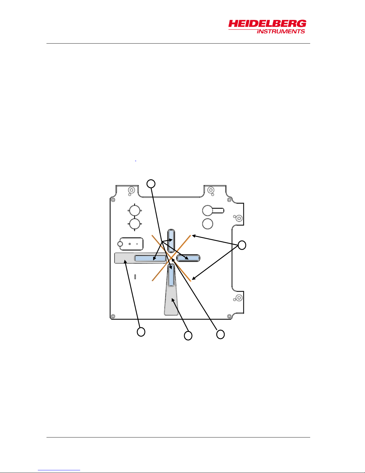
The stage carries the frame in which the chuck is located. There is one chuck for all
substrate sizes. The substrate is hold down and kept it in place by vacuum suction.
The chuck features a vacuum suction hole in the center and four small vacuum slits
through which the vacuum reaches the substrate. Due to the viewing slots, backside
alignment is possible without installing a different chuck. One of the slots is
surrounded by a recess in which the adjustment aid is inserted to provide proper
substrate placing on the chuck. Another one is also surrounded by a recess giving
space for a tweezer to facilitate substrate loading.
1
VIEWING SLOTS
2
VACUUM SUCTION SLITS
3
VACUUM SUCTION HOLE
4
RECESS FOR TWEEZER
5
RECESS FOR ADJUSTMENT AID
2
3
4
5
Page 25
MLA150
3 System Description
User Guide 19
OPTICS PLANE
The optics system is located on a smaller granite top plate supported by the base
plate and its granite side elements. The optics plane contains the optical elements
and all camera components. The write head stands at the end of the optical path
and is mounted to this plate with downward beam direction facing the substrate.
1
INTERFEROMETER HEAD
2
OPERATOR PANEL
3
STAGE
4
CHUCK
5
WRITE HEAD
6
OPTICS PLANE
Figure 6: Stage system with optics plane
1
4
6
5
2
3
Page 26

MLA150
3 System Description
20 User Guide
3.1.3 OPTICS SYSTEM
DIGITAL MICROMIRROR DEVICE (DMD)
The DMD is an electrical input and optical output micro-electric-mechanical system
for spatial light modulation. It is composed of an array of micro light switches
containing individually controlled micro mirrors which correspond to the pixels in the
image to be displayed. Laser light is modulated by this device to project and transfer
a pattern into positive or negative resist.
LASER UNIT AND OPTICAL ELEMENTS FOR BEAM GUIDANCE
The laser beam is emitted by several laser diodes, coupled in an optical fiber and
projected on the DMD. The optical elements guide the modulated light through the
system. The light beam passes the write head and is finally projected on the
substrate.
CAMERA UNIT
The camera unit comprises one camera with low resolution, one with high resolution
and one overview camera. The cameras also feature a light source and make it
possible to inspect and measure the exposed substrates. Additionally, the cameras
are used for accurate alignment of a design with existing structures. Here, the High
Res camera is the appropriate choice due to its high resolution. In cases where the
alignment marks are larger than the field of view of the High Res camera, switching
to the macro camera is recommended. The overview camera is not appropriate for
alignment. Additionally, it does not show the complete surface of the substrate due
to mechanical limits. The camera image is transferred to the User PC via camera
software that opens in its own window. Systems with backside alignment have a
second camera unit for back side viewing mounted inside the stage and looking
pointed to the substrate.
PNEUMATIC AUTOFOCUS
The pneumatic autofocus serves to keep the focal point of the write beam stable on
the surface of the substrate. For probing the distance, compressed air passes
through the write head and leaves it through a nozzle. Once the write head is close
enough to the substrate, a pressure builds up between the nozzle and the substrate,
which is monitored by a pressure sensor. The pressure sensor transmits the
information to a controller which regulates the write head movement. The defoc
value shows the focus position of the write head with respect to the offered
Camera type
Field Of View
(size of the substrate area that can be seen)
Top Surface
Back Surface
High Res
190 μm x 140 μm
min.172 x 130 µm
Low Res
640 μm x 480 μm
min 364 x 274 µm -
Overview
20 mm x 20 mm
top side only
*Overview cannot access the entire surface of the substrate due to mechanical
limits.
Table 1: Field of view (top side, back side)
Page 27

MLA150
3 System Description
User Guide 21
defocusing range [-10 to 10]. This range is necessary to adapt the focus distance to
an appropriate value which mainly depends on resist thickness and thus varies.
INTERFEROMETER
The laser interferometer is an optical device for measuring the stage position. The
machine achieves its required positioning precision with this important element.
WRITE HEAD
The write head is mounted to the optics plane. The focal length of the write lens
determines the resolution of the system.
Interferometer
Laser Unit
(HeNe)
X Mirror
X interferometer unit
Y interferometer unit
Stage
Y Mirror
Figure 7: Interferometer function
Page 28

MLA150
3 System Description
22 User Guide
3.2 Electronics Rack
The electronics rack consists of several units. These units drive and control the system
and provide communication with the operator of the system. The following electronic
units are located inside the electronics rack:
1 USER PC WITH CONVERSION
The User PC is a communication interface
between user and system by means of the
graphical user interface (GUI). The User PC
runs Linux on a virtual machine which runs the
conversion software. This software is
necessary for design conversion. Design files
in Gerber, DXF, CIF or GDSII have to be
converted into a machine file format, the LIC
format. LIC stands for Laser Internal Code.
Only this special file format can be read by the
MLA system.
2 STC-RACK
The STC-Rack is a system control unit
consisting of several elements such as the
stepper motor driver, the autofocus electronics
or the laser shutter control.
3 STAGE CONTROLLER
The Stage Controller drives the stage, reads
the interferometer data, triggers the laser and
tells the DMD (digital micromirror device) when
to switch to the next frame. It is the system that
coordinates the exposure procedure.
4 POWER SUPPLY AND EMERGENCY STOP
MODULE
This unit responsible for power distribution.
5 INTEGRATED NETWORK HUB
The Integrated Network Hub connects the
multiple devices and make them work together
on a single network.
1 2 3
4
5
Figure 8: E-rack components
Page 29

MLA150
3 System Description
User Guide 23
3.3 Orientation of Stage and Design
It is important to load the substrate with the correct orientation on the center of the
chuck. The coordinate system of the design to be exposed must match the direction and
orientation of structures already exposed on the substrate.
The coordinate system of the stage is oriented such that the y-axis corresponds to a
left-right movement and the x-axis to a backward-forward movement (see Figure 9)
when standing in front of the machine.
The design is exposed rotated by 90 degrees in clockwise direction (Figure 10).
X
loading side
F
90°
clockwise
Figure 10: Machine-related design rotation
F
Figure 9: Orientation of stage and design
Page 30

MLA150
3 System Description
24 User Guide
Thus, the coordinate system of the design is also arranged rotated by 90 degrees
clockwise (Figure 11).
For easier orientation on the chuck regarding the design coordinates, the following
figure gives an example of alignment crosses and their location on the substrate.
-x
-y
+x
+y
+x
- y
- x
+y
90°
clockwise
-x
-y
+x
+y
+x
- y
- x
+y
Figure 11: Rotation of coordinate system on chuck
loading side
Figure 12: Location of coordinate pairs
1
4
2
3
loading side
Page 31

MLA150
4 Wizard Description
User Guide 25
The MLA150 offers quick setup of exposure and alignment aided by the Exposure
Wizard. This intuitive user interface guides the operator through the steps of an
exposure set up. To start the wizard, double-click on the link icon.
4.1 Overview: Exposure Wizard
The Exposure Wizard has its own window. This window stays open throughout the
entire configuration and exposure procedure (Figure 13). It contains the following main
elements:
MENU BAR
TAB SECTION
INFO SECTION
FRAMES
INFO FIELD
NAVIGATION
BUTTONS
PANEL
Figure 13: Wizard window overview
Page 32

MLA150
4 Wizard Description
26 User Guide
MENU BAR
The menu bar is located at the top of the window, offering a number of menu utilities.
INFO SECTION
The info block gives information about the hardware condition and the progress or
status of the current exposure setup.
PANEL
The panel is located below the info section. This panel changes according to the
tasks that the system has to perform. In figure 13 the panel’s name is Setup Job
panel. Inside the panel are buttons and frames.
FRAME
The panel contains frames e.g., the Layer frame, where the design file and other
options are selected. The frame has mandatory fields that have to be filled with
values, and fields that can be filled optionally. The mandatory fields are highlighted
in orange and turn green once a value has been entered. The optional fields are
highlighted in green before and after the entry of values.
Throughout this manual you find instructions like "double-click Design". In this case,
you are instructed to double-click the value field with the title Design not the word
Design.
BUTTONS
A click on these buttons usually opens another window where you can select items
or set options
NAVIGATION BUTTONS
At the bottom of the wizard window, you find navigation buttons e.g., Load
Substrate or Continue. The functions and names of the buttons depend on the
selected exposure mode. These buttons can stay disabled until certain tasks are
finished.
INFO BOX
Every panel contains a yellow text box, giving information and instructions on the
current task.
TAB SECTION
A block with two tabs is located below the menu bar. In one tap (Exposure Setup) a
tree view shows the procedure steps the system has to execute. The other tab (Info)
shows a list of startup messages (refer 4.2 Static Wizard Elements for more details).
In the following subchapter, you find detailed information about the Exposure Wizard
elements.
TITLE
VALUE
MANDATORY
OPTIONAL
Page 33

MLA150
4 Wizard Description
User Guide 27
4.2 Static Wizard Elements
4.2.1 MENU BAR
FileExit:
To leave the wizard and close the window
ToolsControl Panel:
Activates the Control Panel (see 7.1 Control Panel)
ToolsInitialize Stage:
To initialize the stage in case the hardware info shows that
it is not initialized
UserSelect User:
Login of a certain user
UserManage Users:
To manage the administration rights of the different users
4.2.2 TAB SECTION
The Exposure Setup Tab shows a tree view of the steps to
be completed with the wizard from job setup to exposure and
unloading. It is a graphical representation of the sequence of
panels making up one exposure job. As a kind of panel map
it can be taken for orientation.
The green rectangle shows the options available in the
selected Exposure Mod. The green check indicates that the
task is done.
The Info Tab shows a list of startup messages informing the
user about the condition of the system after startup.
The control system checks the communication between the
electronics and the hardware components. A list of exposure
files and exposure reports is shown featuring a search bar for
easy retrieval of exposure information.
Note:
If the Hardware Info Section shows a red cross,
open the Info Tab and check the startup messages
to find out where the problem is.
Page 34

MLA150
4 Wizard Description
28 User Guide
4.2.3 INFO SECTION
The Info Section consists of four subsections:
Exposure Info
Alignment Info
Progress Info
Hardware Info
Exposure Info
Job Name is a combination of the word job and the job number. It is editable in the
Job frame by double-clicking into the Job Name value field.
No. shows the auto-incrementing number of the job, it is not editable.
Substrate Size[mm] shows the size of the substrate that is currently loaded.
Design Name shows the name of the design that is currently loaded.
Design Size [mm] shows the size of the design.
Dose [mJ/cm²] shows the exposure energy for the current job.
Height shows the height of the substrate on the cuck.
Layer shows the layer that is currently being prepared for exposure.
Mode shows the exposure quality level chosen at conversion. Quality means high
level, Fast means lower quality level but faster completion.
Defoc shows the defocus value selected for the current exposure. The defoc with a
range between -10 to 10 allows fine tuning of the exposure focus (for more
information see 3.1.3 Optics System: Pneumatic Autofocus). This value can be
adjusted before starting the design exposure (6.8 Expose Design)
Page 35

MLA150
4 Wizard Description
User Guide 29
Alignment Info
This info box has two tables:
Expose Cross Positions shows the positions of the alignment crosses set during the
setup of the layer previous to the layer with the design that is to be aligned. For
instance, when setting up the First Exposure job the coordinates of the exposure
crosses for the next layer can be determined and exposed together with the First
Exposure layer.
Align Cross Positions shows the positions of the alignment crosses taken from the
template file. For orientation regarding the location of the coordinate pairs on the
substrate see 3.3 Orientation of Stage and Design.
Progress Info
The Progress Info box gives information about the progress of the exposure.
Exposure Status shows the status of the exposure job.
Design Number shows the number of the design that is being exposed.
Page 36

MLA150
4 Wizard Description
30 User Guide
Stripe Number shows which stripe is being exposed at the moment.
Time [hh:mm]. shows the time that the exposure takes in total.
Remaining Time [hh:mm] shows the time that the exposure is still requiring to be
finished.
Hardware Info
The Hardware Info box shows important information about the system status. The
Refresh button updates the information stated in the tables. The Stage Position fields
show the x-coordinate and the y-coordinate of the current stage position. A click on
Refresh updates the fields to show the current position.
The Status list informs about the status of the system devices. If there is a red cross
instead of the word OK, click Refresh. If the status is still the same, go to the Info Tab
and click Status Messages. Here, you can see why the status does not show OK.
The Numeric Values list shows the condition of the system parts in numeric values.
These values are only interesting for service staff or users with administrator rights. If
any of the values is not in the normal range, the Status list shows the red cross icon
instead of the word OK.
REFRESH
STAGE POSITION
Page 37

MLA150
4 Wizard Description
User Guide 31
4.3 Substrate Representation
In the menu panel you find a simple graphical depiction of the substrate showing the
design position on the substrate. The position of the camera is also displayed in order to
see which part of the substrate is currently visible in the camera image.
Depending on the kind of substrate shape (plate or wafer) the menu offers two different
substrate visualizations. On the substrate, the design position and size is displayed by a
red rectangle. The camera is depicted as a blue rectangle.
1
Camera
2
Design
1
2
Page 38

MLA150
4 Wizard Description
32 User Guide
The horizontal and vertical measure lines indicate the real size of the substrate. The
size of the design representation and the size of the camera are scaled in relation to
these measure lines.
To move the design to a certain position on the substrate, use the Control Panel.
Alternatively, drag the camera (hold mouse button down while moving) to the desired
location. The design follows when the camera position is set to zero by clicking Set zero
in the Control Panel.
Page 39

MLA150
5 System Startup
User Guide 33
This chapter describes how to power up and power down the MLA150. For powering up
and down the system the buttons at the front of the flow box are used.
5.1 Powering Up
Powering up the system:
If not already done, switch on the main switch at the e-rack.
Allow 60 seconds to boot the power supply.
Depending on the system configuration, switch on the User
PC.
To switch on the system power, press the On (I)-button at the
front of the flow box.
You can hear one click and another click 3 seconds later.
In case the system was switched off by using the EMERGENCY OFF button:
Release by turning it in the direction indicated on the button. Otherwise the
system power cannot be switched on.
Press the green On (I)-button.
You can hear one click and another click 3 seconds later.
Note:
If power is not coming up, check whether the main
breaker on the bottom of the electronics rack is turned
off. Turn on the main breaker again!
Switch on the displays and the User PC, if it is not running.
In case the power supply was interrupted (e.g. by a blackout)
Press the green On (I)- button.
You can hear one click and another click 3 seconds later
Reboot the User PC.
Starting the Exposure Wizard:
Click the shortcut at your desktop.
On (I)
Off (0)
Emergency
Off
Page 40

MLA150
5 System Startup
34 User Guide
At each startup, the menu checks for necessary component initializations. A
window shows the status of hardware initialization
5.2 Powering Down
Powering down in emergency case:
In case of emergency, press the EMERGENCY OFF button at the front of the flow box.
Standard power down procedure
Close the Exposure Wizard by selecting FileExit from
the menu bar.
Shut down the User PC.
Press the red Off (0) – button.
The system shuts down.
Complete Shutdown
Execute the standard power down procedure and then turn off the
main breaker that is located on the front of the power distribution
rack at the bottom of the electronics rack (see 3.2 Electronics Rack).
Note:
In general, the system should be powered down completely only if
absolutely necessary. If the exposure laser is off, idle power consumption of
the system is low, and keeping it in standby enhances stability.
We do not recommend to power down the system if the idle time period is
less than at least one week.
Powering down for maintenance
The main circuit breaker in the bottom compartment of the electronics cabinet is
equipped with holes for a padlock. If the system is powered down for maintenance or
servicing, after above steps, secure the main circuit breaker in the Off position with such
a padlock.
On (I)
Off (0)
Emergency Off
Page 41

MLA150
6 Job Setup
User Guide 35
As mentioned before (4 Wizard Description), the MLA150 provides an exposure wizard
that guides the user through the steps needed to perform an exposure. The following
subchapters build a sequence of actions that have to be executed one after the other.
To use the wizard efficiently, follow the instructions given in this chapter. The following
figure is a “panel map” showing the way through the wizard panels.
Load
Substrate
Unload
Substrate
Setup Job
Select Job
Select Substrate
Template
Load Design
(Convert Design)
Exposure
Alignment
Alignment:
Exposure
Series
First
Exposure
Draw Mode
Page 42

MLA150
6 Job Setup
36 User Guide
6.1 Select Job
To start the wizard, double-click on the desktop. The Exposure Wizard opens
and automatically creates a new job. This job has a Name and a Number. The name is
editable and can be changed by clicking into the Name field. The number is fixed and
auto-incrementing.
If you do not intend to start a new job, you can also choose from the following options:
Continue or repeat a job:
Click Load Job.
Repeat an exposed layer of that job:
Click Restart Job and select the job you would like to repeat. The process
data of the selected job is deleted and a new job is set up with the same
settings but with a new job name/number.
Start another new job after you have finished an exposure job:
Click New Job. The new job has a new number and a new, but editable,
name. Continue with the instructions for a new job.
Use the new job that has started automatically with wizard startup:
From the dropdown list, select one of the available exposure modes:
Standard:
To expose a single design for each layer. Overlay exposures
are possible in this mode.
Series:
To expose designs (e.g. dose test) several times at different
positions with varying parameters (dose or/and defoc). It can
Page 43

MLA150
6 Job Setup
User Guide 37
also be used for finding the appropriate dose and defoc
relation for the exposure.
Draw Mode
To create boxes, circles or ellipses of arbitrary size limited
only by the camera field. Used for creating connections
between structures or for repairing imperfections in structures
of an exposed layer.
After you have set up the desired job, choose the appropriate substrate and the
corresponding substrate template at the system (see Substrate Template Selection).
6.2 Select Substrate Template
The system also needs to be provided with the information about the chosen substrate.
It offers a list of templates. In case the required template is not available in the list, it is
possible to load a new substrate template (only for authorized users).
For selecting a substrate template, follow these instructions:
In the Substrate frame:
Double-click into the value field titled Substrate Template.
From the list, select your substrate size or at least the shape e.g.,
automatic_round if you intent to load a wafer.
Above the list, click Load.
The Substrate frame now displays the selected substrate size or shape and the
field is highlighted in green. That means that the task of substrate template
selection is done. If a substrate size was selected the fields Size X, Size Y,
Diameter and Thickness are filled with the corresponding value.
1 1 3
2
Page 44

MLA150
6 Job Setup
38 User Guide
6.3 Load Design
In Draw Mode there is no design loading procedure because this mode is for
exposing boxes, circles and ellipses of arbitrary size limited only by the camera
field. Skip this subchapter and go to 6.5 Load Substrate.
After you have selected one of the exposure modes (see 6.1 Select Job) and
determined the appropriate substrate template (see 6.2 Select Substrate Template), you
load the design. For loading a design that is not in the list, follow the instructions given
in 6.4 Convert Design. The following sections contain instructions on design loading.
Even though the loading procedures differ only slightly from each other in the different
modes, read the section that corresponds to the exposure mode you are about to use.
6.3.1 STANDARD: FIRST EXPOSURE
In the Layer frame:
If available, select a laser from the dropdown list in the Laser field.
Double-click into the value field titled Design. A panel opens containing a list of
available design files.
From the list, select the required design with a left-click.
Click Load. Alternatively, double-click on the design name.
i
Page 45

MLA150
6 Job Setup
User Guide 39
The design is now listed in the Layer frame.
Optional: Double-click the value field titled Resist and select the appropriate
resist type for your application. The recommended dose for exposures on that
type of resist is listed automatically in the Sensitivity field. In the Thickness field
the thickness of the resist is displayed. Select the wavelength for the exposure.
Optional: It is possible to load a template for alignment crosses which are
exposed on the layer. To load this template, double-click into the value field titled
Expose Crosses and select a bitmap template file from the list. If the template
size exceeds 800 x 600 px, the system shows a warning.
6.3.2 STANDARD: ALIGNMENT
For aligned exposures, Layer 2 is the first layer that can be chosen.
If available, select a laser from the dropdown list in the Laser field.
Double-click into the value field titled Design in Layer 2. A panel opens containing
a list of available design files.
From the list, select the desired design file with a left-click.
Click Load. Alternatively, double-click the name.
1
4
Page 46

MLA150
6 Job Setup
40 User Guide
The design is now listed in the Layer frame.
Double-click into the value field titled Align Crosses. A list opens showing
several templates with the crosses required for alignment procedures. A special
template called _Manual.xml is offered for cases in which the cross positions
should be selected in the alignment setup. The exposure is then executed with
the manually selected alignment positions which are saved afterwards as
[jobname]_AlignPos_L[No. of layer] (see below). Additionally, if a
different template was selected, alignment positions can be changed or even
ignored (see 6.7 Setup Overlay Alignment).
From the list, with a left-click select a template and click Load.
The template file is now listed in the Align Crosses field.
Optional: Double-click into the value field titled Resist and select the appropriate
resist type for your application. The recommended dose for exposures on that
type of resist is listed automatically in the Sensitivity field. In the Thickness field
the thickness of the resist is displayed. Select the wavelength for the exposure
Note:
If the first layer does already exist on the substrate, it can be easily skipped.
6.3.3 SERIES
In Series Mode the template and design file is selected automatically when choosing
Series Mode in the Set up panel (see 6.1 Select Job). The Layer frame turns into the
Series frame with different parameters than displayed in the Layer frame (see below).
In case you need a different design file for your series exposure, follow the instructions
given in 6.3.1 Standard: First Exposure.
Page 47

MLA150
6 Job Setup
User Guide 41
6.4 Convert Design
If you have chosen a listed design file, skip to the next section 6.5 Load Substrate. For
converting a new design, follow these instructions:
In the Layer frame:
Double-click into the value field titled Design. A page containing a list of designs
opens. At the bottom you find a button bar.
Click Convert Design. You are led to the conversion software window.
Page 48

MLA150
6 Job Setup
42 User Guide
In the Conversion window:
From the menu bar, select File New Job (alternatively click the sheet icon).
You are asked to enter a name for the job. Enter a name and click Ok.
Click Add, select a design format. A directory opens containing the source files
for the selected design format.
From the directory, select the file to be converted into the LIC format.
If necessary, change settings and / or use the viewer application (see related
document Conversion Job Manager for more details).
Click Complete Task. A message box informs about the completion of the
process.
If the status bar shows 100%, click Finish.
The conversion software closes automatically.
Click into the wizard window to refresh the design list or click Refresh. The new
file is now listed and available for exposure.
Page 49

MLA150
6 Job Setup
User Guide 43
6.5 Load Substrate
After you have chosen the appropriate substrate, selected a substrate template and
loaded a design, you can place the substrate on the chuck. The following instructions
guide you through the loading procedure. You also get on-screen instructions inside the
yellow Info Box.
The chuck is designed to facilitate the manual loading process. It has an indentation
surrounding one of the four viewing slots for backside alignment. This indentation
makes substrate handling on the chuck easier as it offers space for putting a adjustment
aid inside.
ADJUSTMENT AID
The guide bar at the bottom of the adjustment
aid is equipped with rest positions
corresponding to the different wafer sizes that
are possible to be loaded on the chuck.
These rest positions are made visible on a
measuring scale.
In the example the chuck is loaded with a 4”
wafer as it can be seen on the measuring
scale matching the mark at the chuck.
Keep in mind to remove the adjustment aid from
the chuck before starting an exposure.
In order to avoid possible damage caused by
this adjustment aid, the system is equipped with
a monitoring function based on a light barrier
control. The Exposure Wizard disables the
buttons that lead to all subsequent steps. The
exposure function stays blocked until the tool is
removed from the chuck.
Page 50

MLA150
6 Job Setup
44 User Guide
STEP-BY-STEP SUBSTRATE LOADING
In the Setup Job panel:
Click Load Substrate. The stage moves into loading position.
The wizard moves on to the Load Substrate panel. Wait until the movement has
stopped.
At the lithography main unit:
Push the window button and release it again. The window
opens.
Place the adjustment aid so that the guide bar, which is
located at the bottom, fits into the indentation at the
chuck.
Adjust the auxiliary tool’s position to the substrate size.
Use a tweezer to grab the substrate and place the
substrate on the chuck.
Note: Check for correct loading and head position.
At the operator panel press the vacuum button.
Make sure that the substrate is held tight by the vacuum.
Remove the adjustment aid from the chuck.
Check the substrate's orientation (see 3.3 Orientation of
Stage and Design).
Close the window by pushing and releasing the button.
Go back to the User PC.
Resist coated substrates get useless when exposed to
white light!
Non-safe light may only be switched on if all substrates are
stored in boxes impermeable to light. Otherwise, the
substrates become useless.
Page 51

MLA150
6 Job Setup
User Guide 45
In the Load Substrate panel, click Continue.
Check if the substrate is placed under the write head. If not, see below. If the
substrate position is correct, click Continue.
Note:
In case the substrate is not placed under the write head, click Cancel. The
stage moves back to loading position. Start the loading procedure again
and make sure that vacuum is switched on.
Note:
For small substrates the system issues a dialog box if the substrate type
has not been completely defined in the step of substrate template selection.
The system searches for the center of the substrate and gives information about
the progress via a message box. If you wish to abort the Find Plate Center
procedure, click Stop in the message box and start the loading process again.
After the successful loading process, the system leads to the next panel:
In Standard Mode with overlay alignment, the Alignment panel appears (6.7
Setup Overlay Alignment).
In Draw Mode, the system offers the Draw Mode panel for creating boxes,
circles and ellipses (6.6 Draw Structures).
In Standard Mode without overlay alignment, you are led directly to the
Exposure panel (6.8 Expose Design).
In Series Mode, the Series panel shows up offering the exposure procedure
(6.8.3 Series Exposure Procedure).
Page 52

MLA150
6 Job Setup
46 User Guide
6.6 Draw Structures
After having selected the appropriate substrate, you can start drawing the image.
In the Draw Mode panel
In the Procedure frame, select the kind of shape to use for image drawing by activating
the corresponding radio button:
Draw Image: Activate this option to use the shapes offered in the camera
window: rectangle, ellipse, circle or bitmap file.
Draw Line or Polygon: Use this option to draw lines or polygones (lines with
more than two points). Adjust the line width by using the spin control below
the radio button.
Expose crosses: Use this option to expose crosses for alignment orientation
without the design (in Standard Mode a design has to be loaded). In the
Expose Crosses table you can load the bitmap file for cross exposure.
Page 53

MLA150
6 Job Setup
User Guide 47
6.6.1 DRAW IMAGE
Click Draw Image and select the area for the structure on the substrate inside the
camera window (use the Stage Control section for moving on the substrate).
In the camera window select the shapes of the structures that should be drawn
onto the substrate by clicking on the corresponding icon.
You can also load an existing file by clicking Load and selecting the file from
the corresponding folder (usually C:\HIMT\Designs\Bitmaps). To directly
load a bitmap file click BMP located below the structure icons.
To drag the structure to the desired position click into the structure and move the
cursor with the mouse button held down. To rotate the structure click into the
green dot inside the structure and move the cursor without releasing the mouse
button until the desired position has been found.
i
Page 54

MLA150
6 Job Setup
48 User Guide
To confirm the drawn image, click Submit in the menu bar of the camera window.
To clear the image, click Clear and start again.
To save the image, click Save, insert a name for the file and save it. To cancel
the entire drawing procedure, click Cancel.
After submission of the created image, work with the camera window is done.
Return to the wizard window and the Draw Mode panel in which the exposure
process can be started (see 6.8.4 Draw Mode Exposure Procedure).
6.6.2 DRAW LINE OR POLYGON
In the camera window, move to the area near to the
position of the first point of the line or polygon, so
that it is visible in the camera image.
Click Set Point.
In the camera window, a crosshair appears. Move
the crosshair by moving the mouse to the desired
position.
i
Page 55

MLA150
6 Job Setup
User Guide 49
Click the left mouse button at the position in which the first point of the line should
be set.
Move to the next point of the line/polygon by using the arrow buttons of the
Control Panel.
Click Set Point. Repeat the set point procedure.
Check the line position in the camera window and click Accept line.
To draw a polygon, go on with the set point procedure and click Accept Polygon
to submit the polygon drawing.
After accepting the drawn shapes, work with the camera window is done. Return
to the wizard window and the Draw Mode panel in which the exposure process
can be started (see 6.8.4 Draw Mode Exposure Procedure)
6.6.3 EXPOSE CROSSES IN DRAW MODE
If not selected in the Setup panel, a bitmap file has to be selected for every cross
position:
Click Edit and select a template for every cross position. For selecting the same
file in every position, activate the checkbox Use first bitmap for all.
Enter the positions into the table.
Click Edit again, to leave the editing mode.
Note:
Use Edit to change the template selection made in the Setup panel. Go to
back to the original positions from the selected file, click Original.
Page 56

MLA150
6 Job Setup
50 User Guide
6.7 Setup Overlay Alignment
For exposing the first layer, skip this subchapter and continue with 6.8 Expose Design.
The MLA150 is able to execute precise alignment exposures. In order to achieve best
results, the system offers top side as well as back side alignment. Back side alignment
(BSA) is realized by a separate camera unit for back side viewing that is mounted inside
the stage and looks to the substrate. Back side alignment is used in the same way as
the normal top side alignment. For using the available alignment modes, choose
standard exposure mode in the Setup Job panel.
Top side alignment is supported by three different camera types as mentioned before
(see 3.1.3 Optics System). Back side alignment is supported by two cameras, low and
high resolution. The overview camera is still active, but provides only top side view on
the substrate.
The Low Res camera is the default camera. For alignment, it is recommended to use
the High Res camera as its higher resolution is leading to best alignment results.
The alignment function offers two different alignment modes, Cross Alignment and
Manual Alignment.
Cross Alignment is an automatic cross detection mode and is recommended to be
used as standard mode.
Manual Alignment is the manual mode for cross detection and is provided for
exceptional cases in which the automatic detection might not work properly.
In this chapter, you find the information necessary for executing alignment for overlay
exposures. The alignment procedures of top side and back side do not differ from each
other, so the following instructions are for both alignment types.
Page 57

MLA150
6 Job Setup
User Guide 51
Alignment Procedure
In the Alignment panel:
If the template _Manual.xml for manual setup of the alignment cross
coordinates was chosen, select Top Surface for top side alignment or Back
Surface for back side alignment from the dropdown list. The other templates
already contain this information.
Choose a camera from the Stage and Camera Control panel:
Top Surface
Back Surface
Field of view
Field of view
Low Res
640 µm x 480
BS Low Res
min. 364 x 274 µm
High Res
190 µm x 140 µm
BS High Res
min.172 x 130 µm
Overview*
20 mm x 20 mm
*Overview cannot access the entire surface of the substrate due to mechanical
limits.
From the Alignment Mode dropdown list choose between Cross Alignment and
Manual Alignment. This selection can be made for very single cross position.
Note:
Using the High Res/ BS High Res camera for alignment is
recommended whereas the Overview camera is not useful for
alignment procedures.
Page 58

MLA150
6 Job Setup
52 User Guide
Double-check the positions of the alignment crosses taken from the template file.
Editing: The Edit button is used for changing the alignment cross positions.
Click Edit and enter new values. To delete one of the cross coordinates,
delete the value and leave the field blank. If, for instance, you intend to skip
the second cross position in the list, delete the value, copy the value from the
third cross position field into it. Leave the third position field blank. To close
the editing process, click Save. The positions are stored in a temporary file
and turned into a permanent template after exposure start. To restore the
original positions from the file, click Original.
If the template _Manual.xml was selected, set the alignment marks
manually by using the Edit function. For every alignment cross enter the
coordinates, click Save and then Accept Position.
Use the Stage Control frame of the Control Panel to move the cross into the
camera center (see 7.1 Control Panel).
Determine the alignment marks in:
A Cross Alignment Mode:
Click Measure. The system measures the position of the cross and moves it
to the center of the camera window. Examine the positions and click Accept
Position to confirm it. The procedure moves on to the next alignment cross.
In the Pos field, the rectangle turns into a check.
In case of unsatisfying measurements see 7.3.1 Unsatisfying Alignment
Measurements.
B Manual Alignment Mode:
Click Measure. In the camera window, a crosshair appears. Move the
crosshair to the position in which the alignment marks should be set and click.
The crosshair turns from green to orange.
Note:
For fine positioning use the arrow buttons. You can switch between
continuous movement (jogging) and stepwise movement. In step
mode enter the step size [µm] for X and Y direction into the
corresponding fields. In the jogging mode, change the driving speed
[µm/s] either by using the slider or by clicking into the corresponding
field and entering the speed manually. Alternatively, click into the
slider field and use the arrow keys for setting the speed
To center the position of the alignment mark inside the camera window, click
Center Cross.
Note: It is possible to skip alignment positions by clicking Skip Position. This
only works if more than two points are available otherwise the button is
disabled. In the Pos field the rectangle turns into a red cross icon indicating
that this coordinate pair was ignored.
i
Page 59

MLA150
6 Job Setup
User Guide 53
Repeat the procedure for all alignment cross positions. Cancelling the alignment
procedure is possible by clicking Cancel. Alternatively, with Setup Job the
alignment procedure gets cancelled and the Exposure Wizard moves back to the
Setup Job panel.
Click Continue.
The design is now prepared for the exposure process. For information on how to
start the exposure process, go to 6.8 Expose Design.
Page 60

MLA150
6 Job Setup
54 User Guide
6.8 Expose Design
The system offers two standard exposure modes, one with and the other one without
overlay alignment. Additionally, it is possible to execute series exposures in order to
determine the appropriate defoc settings and dose settings for the current exposure job.
In Draw Mode you skipped the design loading and created your own structures directly
on the substrate inside the camera window (6.6 Draw Structures). The following
sections give instructions on how to execute exposures in the different modes.
6.8.1 FIRST EXPOSURE PROCEDURE
After having loaded the design and the substrate, you are in the First Exposure panel.
Double-check the design name and the wavelength.
If no default value is given, set the Dose by entering the value into the text field.
Set the Defoc by selecting a value with the spin button [-10 to 10]. The defoc
allows fine tuning of the exposure focus.
Optional: Activate Auto-Unload (see 6.9 Unload Substrate).
Optional: Activate Expose Crosses if having selected a template before (see
6.3.1 Standard: First Exposure). Use Edit to change the coordinates or load a
different file. It is also possible to load a template here if not having done it before
in the design selection. Use Original to reset the coordinates to the values given
by the template file.
Click Start Exposure.
Page 61

MLA150
6 Job Setup
User Guide 55
The machine is exposing the design. If Auto-Unload is
not activated, then after completion of the exposure a
dialog window pops up asking if the substrate should be
unloaded. Click Yes, if you want the system to unload
the substrate or No if the substrate should stay loaded
on the chuck e. g., to expose the next layer.
It is also possible to click No and unload the substrate by clicking Unload in the
panel (see 6.9 Substrate Unloading).
6.8.2 OVERLAY EXPOSURE PROCEDURE
After having loaded the design and the substrate and having prepared the alignment
crosses, the substrate is ready to be exposed.
In the Alignment: Exposure panel
Double-check the design name and the wavelength.
If no default value is given, set the Dose value by entering it into the text field.
Set the Defoc by selecting a value with the spin buttons (range -10 to 10). The
defoc allows fine tuning of the exposure focus.
Double-check the Alignment Cross Positions.
Optional: It is possible to load a template for alignment crosses which are
exposed on the layer. To load this template, double-click into the value field titled
Expose Crosses and select a bitmap template file from the list
Chose from the Alignment Options section:
Page 62

MLA150
6 Job Setup
56 User Guide
Rotation [mRad]: If the Use checkbox is activated, the system calculates the
rotation of the substrate.
Scaling X/Y: The system compares the distance measured during alignment
with the distance given by the alignment positions. From the deviation a
scaling factor results. On this basis the alignment design is shrunk or
stretched in order to match the previous layer.
Shearing [mRad]: The system compensates small distortions such as a
rectangle that appears more like a parallelogram.
Optional: Activate Auto-Unload. The system executes the unloading procedure
automatically (see 6.9 Unload Substrate).
Click Start Exposure.
The machine is exposing the design. If Auto-
Unload is not activated, then after completion
of the exposure a dialog window pops up
asking if the substrate should be unloaded.
Click Yes, if you want the system to unload the
substrate or No if the substrate should stay
loaded on the chuck e. g., to expose the next
layer.
Page 63

MLA150
6 Job Setup
User Guide 57
6.8.3 SERIES EXPOSURE PROCEDURE
After having loaded the substrate and the design, the substrate is ready to be exposed.
You are in the Series panel of the Series mode.
In this panel several values have to be set for series exposure. Find the explanation of
the panel elements below:
Mode: Three different selections are possible: Dose, Defoc
or Dose and Defoc.
Number of fields: Use the spin button to select the number
of fields to be exposed
In the Dose Series table, you set the parameters for the
series with varying energy values.
In the Defoc Series table, you set the parameters for
exposing the design with varying defoc values. The defoc
allows fine tuning of the exposure focus.
In the bottom table, the Step size in x and y direction is
determined.
Pay attention to the value in the Total range fields. If the
total range requires more space than available on the
substrate, an error message pops up.
For information about Auto-Unload and Unload see 6.9
Unload Substrate.
Page 64

MLA150
6 Job Setup
58 User Guide
When choosing Dose Series only, the Defoc value is fixed. The Dose value is fixed
when Defoc Series is active.
The substrate visualization shows the arrangement of the fields according to the values
set in the Series panel. This feature facilitates the preparation of series exposures. The
horizontal fields are for defocus series and the vertical fields represent the dose fields
(see below). If the fields overlap, the step size has to be changed to a higher value. If
the field arrangement exceeds the substrate surface size, the number of fields has to be
reduced.
Select from the options in the Mode dropdown list: Dose, Defoc or Dose and
Defoc.
Set the values required for the selected mode.
Note:
Pay attention to the value in the Total range fields. If the total range
requires more space than available on the substrate, an error message
pops up.
If desired, activate Auto-Unload (see 6.9 Unload Substrate).
Click Start Exposure.
Page 65

MLA150
6 Job Setup
User Guide 59
The machine is exposing the design. If Auto-Unload
is not activated, then after completion of the
exposure a dialog window pops up asking if the
substrate should be unloaded. Click Yes, if you want
the system to unload the substrate or No if the
substrate should stay loaded on the chuck e. g., to
expose the next layer.
6.8.4 DRAW MODE EXPOSURE PROCEDURE
After creation and submission of the image, you are still in the Draw Mode panel to start
the exposure.
In the Draw Mode panel
Set the Dose value by entering the value into the text field.
Set the Defoc by selecting the value with the spin buttons (range -10 to 10). The
defoc allows fine tuning of the exposure focus.
Optional: Activate Auto-Unload. The system executes the unloading procedure
automatically (see 6.9 Unload Substrate).
Click Start Exposure.
In the Progress Info section the table changes to a list displaying the Draw Mode
procedures that are already executed. The most recent one is listed at the top of
the list. You also find the information about the type of draw mode image and the
coordinates of the center of the image.
Page 66

MLA150
6 Job Setup
60 User Guide
6.9 Unload Substrate
For unloading the substrate the system provides a function called Auto-Unload. This
function is selectable by activating a checkbox. Read more in the information below.
Auto-Unload
The Auto-Unload function automatically brings the stage into unloading position directly
after exposure completion. Activate the Auto-Unload function by clicking into the
checkbox before starting the exposure procedure. Above you see where this
checkbox is located in the panels of the different exposure modes (in Draw Mode same
location as in First Exposure Mode). After the unloading procedure had finished, the
wizard directly leads you back to the Setup Job Panel where you can start a new job
with New Job. You can take the substrate from the chuck or leave it there for exposing
a further layer.
Unload
Next to the Auto-Unload checkbox there is an Unload button. Alternatively, it is
possible to click this button after exposure completion. The stages moves into
unloading position. You can take the substrate from the chuck or leave it there for
exposing a further layer. To start a new job, go back to Setup Job panel by clicking on
the corresponding navigation button.
Figure 14: Unloading options in Standard Mode and Series Mode
Page 67

MLA150
6 Job Setup
User Guide 61
Removing the substrate from the chuck
To remove the substrate from the chuck, follow the steps below:
Push the window button and release it again. The window opens.
At the operator panel switch off the vacuum.
Carefully take the substrate off the chuck and stow it in an opaque box
impermeable to light.
Close the window by pushing and releasing the button. If required, click OK in the
Exposure Wizard to close the unloading dialog.
Resist coated substrates get useless when
exposed to white light!
Non-safe light may only be switched on when all
substrates are stored in boxes impermeable to light.
Otherwise, the substrates become useless.
Note:
This user guide does not give instructions on substrate processing. Processing of
the substrate should happen according to the substrate manufacturer's
recommendation.
Page 68

MLA150
6 Job Setup
62 User Guide
Page 69

MLA150
7 System Utilities and Tools
User Guide 63
The MLA offers further elements beside the main menu that facilitate handling the
exposure and alignment processes.
7.1 Control Panel
The Control Panel is a utility that provides navigation functions as well as other
necessary control functions.
In the Camera Control frame, the button for selecting the available cameras are
arranged. A selection is done by clicking the button for the camera of choice. The
camera is then activated. The information about the field of view of the different
cameras helps to make the decision which on to choose for the current application. For
alignment it is recommended to use the High Res camera as its high resolution is best
for alignment procedures
Top Surface
Back Surface
Field of view
Field of view
Low Res
640 µm x 480
BS Low Res
min. 364 x 274 µm
High Res
190 µm x 140 µm
BS High Res
min.172 x 130 µm
Overview*
20 mm x 20 mm
*Overview cannot access the entire surface
of the substrate due to mechanical limits.
Below these you find one Focus slider for setting the camera focus and a Brightness
slider for setting the brightness of the camera image.
Click on the slider and keep the mouse button held down while moving it to the desired
value on the slider bar. Alternatively, click on the slider bar and use the cursor keys for
moving the slider along the bar. The tick marks on the focus slider bar are for your
orientation within the range from −10 to +10 so the center tick mark sets the focus to 0.
Page 70

MLA150
7 System Utilities and Tools
64 User Guide
A positive number brings the laser focus closer to the surface, exposing deeper into the
resist.
The Stage Control frame provides arrow buttons for moving on the substrate surface.
Every click is one movement. They are also used for fine positioning.
To determine the kind of movement, you can switch between continuous movement
(jogging) and stepwise movement by clicking into the corresponding field. In jog mode,
change the driving speed [µm/s] either by using the slider or by clicking into the value
field and entering the speed manually. Alternatively, click into the slider field and use the
arrow keys for setting the speed. In step mode, enter the step size [µm] for X and Y
direction. The arrow buttons for navigation on the substrate surface change their
appearance according to the selected mode. This contributes to a fast identification of
the mode currently selected.
The Set Zero button allows to set an arbitrary point as zero coordinates. With Move To
Zero it is possible to go to the zero point set before. Clicking Substrate Center allows
to move the field of view to the center of the substrate. To stop any stage movement,
make use of the Stop button.
Page 71

MLA150
7 System Utilities and Tools
User Guide 65
7.2 Camera Window
Together with the wizard we provide a camera software that opens in an individual
window. The window is only for viewing purposes and is navigable by using the Control
Panel (see 7.1 Control Panel). The example below shows the camera window
performing a manual alignment.
Figure 15: Camera window
Page 72

MLA150
7 System Utilities and Tools
66 User Guide
7.3 Optimizing Alignment and Exposure Results
7.3.1 UNSATISFYING ALIGNMENT MEASUREMENTS
Sometimes the measurements during the alignment process might be unsatisfying due
to bad contrast caused by uneven surface conditions or low reflectivity of the substrate.
This chapter gives advice how to improve the measurement results during the alignment
process.
Repeat the measurement
Clicking Remeasure repeats the measurement procedure which can lead to new
results. The Measure button turns into the Remeasure button after the first
measurement procedure for one coordinate point.
Change the size of the detection area
For the finding cross function to work properly it is important that the alignment cross
fills the entire camera window. If this is not the case, click ResizeDetectionArea. Inside
the camera window, a rectangle appears showing the new detection area. To enlarge
the detection area, click the right bottom corner of the rectangle without releasing the
mouse button and drag the corner to the desired size while holding down the mouse
button. To resize the detection area again, click MaximizeDetectionArea.
Change settings in the Control Panel
Adjust the values for Focus or Brightness to make the finding cross function work
more efficiently.
Choose a different camera, to get a better view on the substrate.
In the Stage Control Panel, switch between Jog Mode and Step Mode.
Switch to Manual Mode
For every single alignment cross it is possible to switch between the two modes for the
alignment procedure. Manual Alignment is the manual mode for cross detection and is
provided for exceptional cases in which the automatic detection might not work properly.
Switch to Manual Alignment and follow the instructions given in 6.7 Setup Overlay
Alignment.
Page 73

MLA150
7 System Utilities and Tools
User Guide 67
7.3.2 UNSATISFYING EXPOSURE RESULTS
Sometimes exposure results can be unsatisfying for the needs of distinctive
applications. The MLA150 offers a way of optimizing the exposure outcomes. It is
possible to adjust the Defoc value or the Dose value. The following section gives details
about how to work with these two values in order to improve exposure results.
The Exposure Wizard offers a series exposure mode (6.8.3 Series Exposure
Procedure). This utility can be used to optimize exposure results by adjusting the
defocus value (Defoc) and/or the energy value (Dose). In order to find the best ratio
between these two parameters a series of exposures with different values can be
executed.
For more information see the relevant chapter on series exposures.
Page 74

MLA150
7 System Utilities and Tools
68 User Guide
7.4 Back Side Alignment
The following section informs about the back side alignment (BSA) preparation and
exposure procedure.
7.4.1 OVERVIEW OF BSA MARKER ZONES
The MLA150 comes with a multi-purpose chuck ready to expose both large and small
substrates.
For BSA, the chuck provides four designated openings. Markers located in these areas
are detected by the BSA camera system and used for alignment.
Each opening is 10 mm wide and 46 mm or 76 mm long. The first edge is located
12 mm or 14.5 mm from the center of the chuck. The BSA markers can be positioned
anywhere in this area.
For easy handling and good resolution, Heidelberg Instruments recommends to position
the markers on the main axis and about 10 mm from the edge of the wafer. Proposal for
marker: cross of size 300 µm x 300 µm, Linewidth 20 µm.
Proposal for marker positions (x/y):
Wafer
size
Marker 1 [mm]
Marker 2 [mm]
Marker 3 [mm]
Marker 4 [mm]
2 inch
+20 / 0
-20 / 0
0 / +20
0 / -20
3 inch
+28 / 0
-28 / 0
0 / +28
0 / -28
4 inch
+40 / 0
-40 / 0
0 / +40
0 / -40
5 inch
+44 / 0
-44 / 0
0 / +44
0 / -44
Page 75

MLA150
7 System Utilities and Tools
User Guide 69
Figure 16: BSA marker zones overview
Page 76

MLA150
7 System Utilities and Tools
70 User Guide
7.4.2 BSA EXPOSURE PREPARATION
Back side alignment is mainly done in two steps. Follow the instructions on the BSA
exposure steps
Step 1:
Expose the pattern on side A with the BSA markers.
Position your markers inside the BSA marker zones. The
recommended cross linewidth is 20 µm.
Prepare a strategy to find the markers during alignment:
a larger cross is easier to find
add small marks for orientation
When using the mirror function during design import,
remember to click update to all layers.
Step 2:
After processing of side A, position wafer on chuck with side B on top
Remove the inlets of the required BSA holes in the chuck.
Define your default marker positions in the MLA150 menu. Select Backside
Camera for this measurement.
Execute alignment exposure as usual.
The coordinate system of the MLA does not change during back side alignment.
Reference is always the top of the wafer. This means:
The x-coordinate changes prefix on the back side of the wafer. A marker that was
written to position +x is now at position –x. When you use the control panel for
movements, the camera picture will move to the left when you click the "to the right"
button.
Side A on top
Side B on top
Figure 17: Orientation on wafer for BSA
Page 77

MLA150
8 Operator Maintenance and Troubleshooting
User Guide 71
This chapter contains some notes on daily maintenance by the operator as well as
some troubleshooting for the most common problems. For more in-depth maintenance
and troubleshooting information, refer to the related document Maintenance Guide.
8.1 Operator Maintenance
MLA systems require some minimal operator maintenance that does not involve
opening any covers or protective panels and can be done by any trained operator.
These tasks are described below.
SYSTEM CHECKS
Before operation the following routine maintenance should be performed:
Clean the chuck surface with a dry clean wipe. Never use Acetone! If more
thorough cleaning is required, use industry-grade ethanol or isopropanol.
Verify that the clean room conditions are within the limits given in the Technical
Data section.
Make sure nothing is placed inside the system that obstructs stage movement
ENVIRONMENTAL ADJUSTMENT
Allow room humidity to come within the specified range before using the MLA150.
If temperature is out of range, determine how long this condition has prevailed.
Adjust room temperature to within the specified temperature range and allow the
MLA150 to stabilize.
For stabilization of the system, allow an amount of time at least equal to the time
the temperature was out of range.
During exposure, the most accurate results are obtained
when the environment remains at a constant temperature
and humidity.
To achieve the optimum accuracy, the substrate requires
thermal stabilization before exposure. This might take some
time depending on the material, thickness and actual
temperature.
The set temperature of the flow box should correspond to
the default room temperature to minimize thermal effects.
Page 78

MLA150
8 Operator Maintenance and Troubleshooting
72 User Guide
8.2 Troubleshooting
This section suggests corrective action for known issues.
MOUSE DOES NOT MOVE
Switch on the monitor. The mouse is connected to the monitor. If the monitor is
switched off or in sleep mode, the mouse is inactive as well.
THE MLA150 DOES NOT EXPOSE
Verify that the AC power cord is plugged into the wall outlet and that the outlet is
receiving power.
Check whether the laser is switched on and running (see if LED is on).
Verify that the loading window is completely closed.
Try rebooting the system.
LINES NOT TO SIZE
Line thickness problems may have the following causes:
Poor developing chemicals
Wrong developing speed
Wrong resist type or thickness
Focus or energy setting incorrect
Out of date resist
THE MLA150 STOPS ANYTIME DURING THE EXPOSURE
The MLA150 reached an end switch because the imaging area was set incorrectly
The interferometer head is broken
The conversion encountered a problem
SUBSTRATES COME OUT COMPLETELY CLEAR
Laser might be off. Check laser status at LED. If LED is not illuminated, laser is not
running.
BAD ALIGNMENT ACCURACY
Check stability of flow box temperature
Check vacuum quality, make sure no vibrations are transferred via vacuum
Check stage vibrations
Check for drift in position measurement with stage standing still in home position to
find if interferometer laser has to be replaced
SCRATCH MARKS ON WAFER EDGE
Page 79

MLA150
8 Operator Maintenance and Troubleshooting
User Guide 73
Edge beads are not removed. Remove edge beads with the appropriate method to
provide uniform thickness of coating across the wafer.
8.3 TeamViewer Software
On the desktop, you find the icon for the TeamViewer Software. This software enables
the service engineer to enter the system via remote connection. It might be possible that
the service person asks for the system's access data.
Start TeamViewer QS by clicking on the shortcut icon on the desktop.
Pass on the access information to the service person. Both, ID and password are
required.
Note:
Keep in mind that the password is regenerated during the start of
TeamViewer QS and differs from the one displayed during the previous start.
Page 80

Page 81

 Loading...