

Page 1

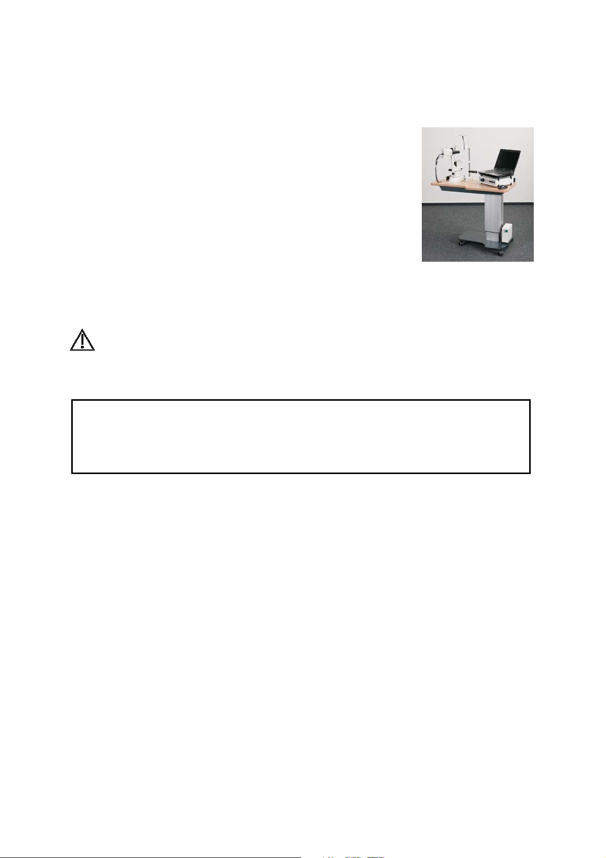
Heidelberg Retina
Camera (HRC)
Installation Instructions
Version 001, May 2009
© Heidelberg Engineering GmbH 2009
Art. No. 20924
QM-Nr. 97 128-001
HRC Installation Instructions Vers. 001 1
Page 2

0482
The manufacturer hereby declares that this product conforms to the
requirements of Directive 93/42/EEC of the Council of the European
Community dated 14 June 1993 regarding medical products (MDD
93/42/EEC).
Caution! Do not use the Heidelberg Retina Camera
without reading this manual. This manual contains
important safety information.
Corporate Headquarters
Heidelberg Engineering GmbH • Tiergartenstr. 15 • 69121 Heidelberg • Germany
Phone +49 6221 6463-0 • Fax +49 6221 646362 • www.HeidelbergEngineering.de
US Main Office
Heidelberg Engineering, Inc. • 1499 Poinsettia Avenue, Suite 160 • Vista, CA 92081
Phone 760 598-3770 • Fax 760 598-3060 • www.HeidelbergEngineering.com
US Service Center
Heidelberg Engineering, Inc. • 410 Harris Road • Smithfield, RI 02917
Phone 401 349-0500 • Fax 401 349-0504 • www.HeidelbergEngineering.com
HRC Installation Instructions Vers. 001 2
Page 3

Table of Contents
1 GENERAL INTRODUCTION ................................................................................................................5
1.1 THE HEIDELBERG RETINA CAMERA......................................................................................................................5
1.2 SAFETY INFORMATION: CAUTIONS AND WARNINGS .......................................................................................5
1.3 MAINTENANCE, CLEANING AND SERVICE..........................................................................................................9
1.4 ACCESSORIES........................................................................................................................................................... 11
2 ELECTRICAL SYSTEM CONFIGURATION.....................................................................................12
3 PC REQUIREMENTS.............................................................................................................................12
4 HARDWARE INSTALLATION ...........................................................................................................13
4.1 CONTROL UNIT (POWER SUPPLY UNIT)............................................................................................................ 14
4.2 HRC CAMERA......................................................................................................................................................... 15
4.3 ASSEMBLY INSTRUCTIONS ....................................................................................................................................16
4.4 CABLE CONNECTIONS........................................................................................................................................... 22
4.5 SOFTWARE PROTECTOR (DONGLE).................................................................................................................... 24
4.6 MOBILE APPLICATION........................................................................................................................................... 25
4.7 MOUNTING AND CHANGING THE LENS ...........................................................................................................25
4.8 FOOT SWITCH .........................................................................................................................................................25
4.9 EXTERNAL FIXATION LAMP.................................................................................................................................. 25
4.10 INSTALLATION OF THE HRC ONTO A SLIT LAMP .......................................................................................... 26
5 TURNING THE INSTRUMENT ON AND OFF...............................................................................27
6 DRIVER AND OPERATING SOFTWARE INSTALLATION.........................................................28
6.1 OPERATING SOFTWARE - FIRST INSTALLATION............................................................................................... 28
6.2 FIREWIRE PERFOMANCE MANGAGER - INSTALLATION ................................................................................32
6.3 VIDEO CONVERTER - DRIVER INSTALLATION ..................................................................................................34
7 TECHNICAL SPECIFICATIONS........................................................................................................37
7.1 OPERATIONAL ENVIRONMENT AND USER TRAINING.................................................................................... 38
7.2 LABELING ................................................................................................................................................................. 39
HRC Installation Instructions Vers. 001 3
Page 4

HRC Installation Instructions Vers. 001 4
Page 5
1 General Introduction
1.1 The Heidelberg Retina Camera
The Heidelberg Retina Camera (HRC) is a scanning digital
opthalmoscope for the examination of the anterior and the posteriorsegment of the eye with or without contrast or fluorescence agent. The
resulting images aid the physician in the diagnosis and the follow up of
various diseases of the anterior and the posterior-segment of the eye.
1.2 Safety Information: Cautions and Warnings
Please read this section carefully and always follow its contents!
1.2.1 General Safety Information
WARNING The light emitted from this instrument is potentially hazardous. The
longer the duration of exposure, the greater the risk of ocular damage.
Exposure to light from this instrument when operated at maximum
intensity will exceed the safety guideline after 30 minutes.
IMPORTANT Before you start working with the instrument, make sure that you know the
correct procedures for turning the instrument on and off (Chapter 5).
IMPORTANT Carefully read the instructions for use before operating the device. Misuse of
the device may lead to hazards for the patient or the operator or can lead to
wrong diagnostic results. Use outside the “intended use” scope may also lead
to instrument damage.
The instrument must not be used if there is a mechanical, electrical, or optical defect.
Modifications or additions lead to loss of the CE mark. Heidelberg Engineering does not
take responsibility for modified HRC devices.
Any repair, especially of the instrument's electric and electronic systems, and any service
work on the instrument components, must only be carried out by Heidelberg Engineering
or an authorized distributor.
1.2.2 Contraindications for Performing Angiography
• Always ask the patient for known allergies and compare it with the
contraindications of the contrast or dye fluid.
• Be aware of possible allergic reactions when contrast or dye fluid is injected.
HRC Installation Instructions Vers. 001 5
Page 6

1.2.3 Cautions, Warnings, and Contraindications
WARNING Carefully read the operation manual before operating the device. Misuse of
the device may lead to incorrect diagnostic results.
WARNING Do not examine a patients eye longer then 30 minutes. A too long
examination time might lead to damages of the retina.
WARNING The camera housing can get very hot after continuous operation. It is
recommended to switch off the device between examinations. Caution is
recommended when touching the camera housing.
WARNING Do not open the device component housings. Doing so may result in
electrical shock.
WARNING Do not use the device outside the scope of its “Intended use”. Doing so may
lead to malfunctions or damage of the device.
WARNING Do not use PCs, components or accessories that have not been approved by
Heidelberg Engineering. Do not install other software, as this may interfere
with the functionality of the Heidelberg Engineering software or equipment,
cause damage to the system or lead to incorrect measurement results.
WARNING Always use a network connection with network isolation in accordance with
IEC 60601-1 (isolating transformer). Without isolation transformer, user and
patient could be at risk of electrical shock in the event of an error.
WARNING Make sure that the environmental requirements are met when the system is
operated. Exceeding environmental conditions may damage the system or
lead to incorrect measuring results.
WARNING Wrong examination preparation of the device and the patient may lead to
bad or insufficient pictures.
WARNING Be aware of possible allergic reactions, when contrast or dye fluid is injected.
Closely follow the package information leaflet. Do not perform more than
one examination per day on the same patient. Multiple injections of the
contrast or dye fluid may result in allergic reactions or shock.
WARNING Incorrect application of contrast / dye fluid may cause allergic reactions or
shock, injury or illness. It may also cause follow up treatment or bad
examination results.
WARNING Make sure the patient is correctly positioned in front of the device before
starting the examination. Wrong positioning may lead to poor images and
incorrect diagnostic results.
WARNING Artefacts on the images could falsify the measured results. Do not use the
measured results if there are artefacts in the images.
WARNING Do not make a diagnostic decision on the basis of one single examination.
The device is not clinically evaluated for the diagnosis of specific
pathologies. So always use alternative information; history data etc. to assist
in a final diagnostic determination.
WARNING Prepare safeguards to ensure that only authorized personnel can access the
patient data. Data loss impedes follow-up analyses and may result in
inappropriate diagnostic decisions.
HRC Installation Instructions Vers. 001 6
Page 7
WARNING Be sure to perform periodic data backup procedures. Check the success of the
backup to avoid data loss caused by backup errors.
WARNING To avoid the risk of electric shock, this equipment must only be connected to
a grounded power supply.
WARNING To avoid the risk of electric shock, do not touch conductive parts of
connectors and the patient simultaneously.
WARNING Do not operate the system directly after large temperature changes. Let the
device acclimate itself for a minimum of two hours to avoid device damage
or incorrect measurement results.
WARNING Clean and disinfect chin rest and headrest or other soiled parts after each
examination, Contaminated parts may lead to infections or disease
contraction.
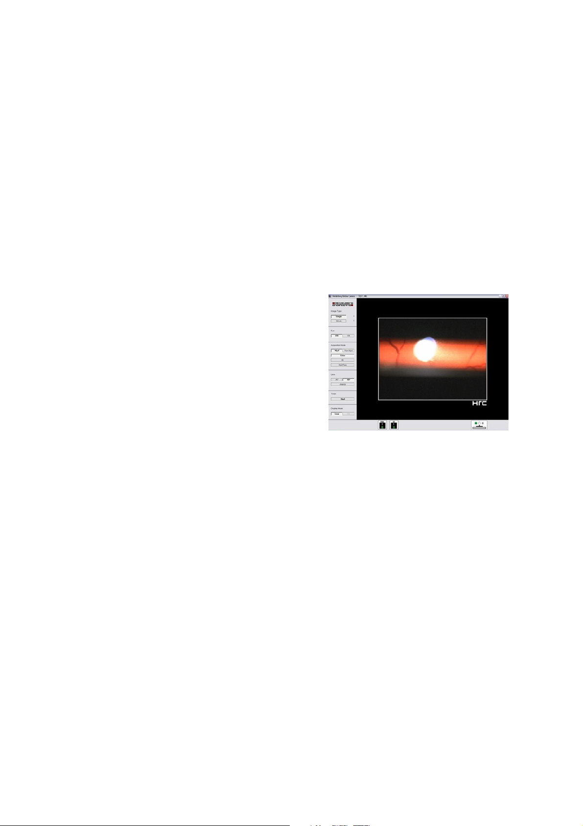
CAUTION In the rare event of defe
ctive
illumination slit, the live image will
appear as shown to the r
ight. The
image shows a small streak in
horizontal direction on the monitor,
whereas the upper and l
the live image are dar
ower parts of
k. In this case,
please turn the instrument off
immediately and contact Heidelber
g
Engineering or the local distributor.
Do not attempt to repai
r the
instrument yourself.
CAUTION Please evaluate all images concerning their image quality (e.g. brightness,
noises, artifacts) before making a diagnostic decision.
CAUTION Please note that the distance or diameter values issued by the Imaging
software are only pixel values and not correlating to a linear dimension. The
real distances are depending on the camera setup, patient distance and
image quality.
CAUTION If the camera or the objective were fallen off, please contact the Heidelberg
Engineering Service for a device check.
CAUTION Please note that vibrations of the device location (e.g. caused by strong
machines) might lead to bad or distorted images.
CAUTION Never leave the patient alone with the instrument during the examination!
CAUTION The instrument must not be used under any circumstances if mechanical,
optical or electrical faults occur. Any change or addition to the system must
comply with the relevant legal guidelines. Repairs, particularly to the
electronic and optical components, must be carried out only by Heidelberg
Engineering authorized, trained personnel.
HRC Installation Instructions Vers. 001 7
Page 8

CAUTION Unusual noises and/or vibrations can indicate a fault. Should this happen,
please turn the instrument off immediately and contact Heidelberg
Engineering or the local distributor. Do not attempt to repair the instrument
yourself in the event of a fault.
CAUTION This equipment was tested in accordance to IEC 60601-1-2, Electromagnetic
Compatibility (EMC). Nevertheless, it might be affected by strong
electromagnetic fields. Portable high frequency communication devices may
affect the device.
CAUTION The operator must be sure that the device settings and adjustments are
correct before starting an examination and making any diagnostic decision.
Wrong settings and adjustments may lead to poor image quality or incorrect
examination information.
CAUTION The physician must be sure to have the correct patient data before making a
diagnostic decision. Mismatched patient data may lead to inappropriate
diagnostic decisions.
CAUTION Do not start an examination without informing the patient about the
examination procedure. Inappropriate patient behaviour during the
examination may lead to poor image quality and incorrect diagnoses.
CAUTION Read subsection 1.5 “ Maintenance, Cleaning and Service” carefully. A
failure to carry out maintenance or incorrect adjustment of the device may
lead to poor image quality and incorrect diagnoses.
CAUTION Before starting the system, check the regional power supply specifications to
verify that they comply with the required tolerances. Wrong power supply
conditions may lead to malfunctions of the system.
CAUTION A computer failure during image acquisition or analysis could lead to
incorrect results.
CAUTION Please note that the effect of environment light might influence the image
quality.
United States of America:
Federal law restricts this device to sale by or on the order of a Physician or Practitioner.
IMPORTANT The HRC light bulb is an especially modified component and not an over
the counter product. Only original spare parts from Heidelberg
Engineering GmbH shall be used.
CONTRAINDICATIONS No contraindications are known.
HRC Installation Instructions Vers. 001 8
Page 9

1.3 Maintenance, Cleaning and Service
The Heidelberg Retina Camera is a precision optical instrument. Protect the instrument
against dust and moisture, and avoid shocks and the action of strong forces.
Beyond the procedures described in this chapter, the operator should not work on the
instrument. Please be aware that only authorized service personnel can do service and
repair of the HRC device. Do not open the camera or power supply unit. If the device is
opened by someone other than an authorized service personnel, the warranty will be
discontinued. For maintenance, adjustment and repair of the equipment contact
Heidelberg Engineering or your local distributor.
A yearly inspection of the device by a Heidelberg Engineering service engineer is highly
recommended to ensure proper and exact operation.
1.3.1 Cleaning and Disinfection
Before cleaning the instrument, turn the instrument off and disconnect the power plug.
The lenses should be carefully cleaned at regular intervals. For this purpose, it is best to use
a cotton swab slightly moistened with 99% ethanol. Do not use disinfection alcohol for
cleaning the optics, as deposits may remain on the lens surface.
The non-optical surfaces of the instrument can be cleaned and/or disinfected as necessary.
Any standard cleaning product appropriate for plastic surfaces which does not contain
acetone or hydrogen peroxide (e.g. ethanol and isopropyl alcohol disinfectants) may be
used for this purpose. Make sure that no cleaning agent penetrates into the equipment.
1.3.2 Changing the Fuse
WARNING: Before changing a fuse the HRC must be switched off and disconnected from the
mains!
The fuses are located in a cartridge (1) in the socket for the mains supply (2) at the back of
the power supply unit.
Remove the cartridge by inserting a small screwdriver behind the flap of the cartridge and
lift the cartridge out of the fuse socket. After exchanging the fuses, insert the cartridge into
the socket.
2
1
1
IMPORTANT: Only fuses with the following specifications are to be used:
100 V-240 V: 2x T 2.0 AL; Size: 5 x 20 mm each, 2-pole fuses.
Always exchange both fuses.
HRC Installation Instructions Vers. 001 9
Page 10
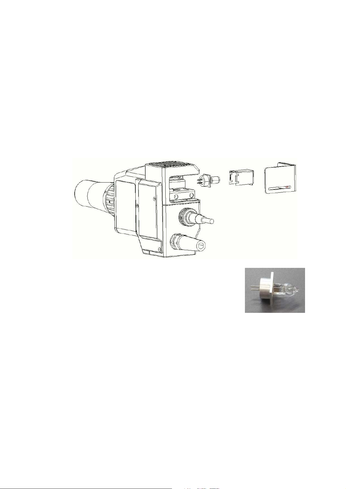
1.3.3 Changing the Halogen Lamp
WARNING: Before changing a halogen lamp, the HRC must be switched off and
disconnected from the mains!
WARNING: The halogen lamp can be very hot! Wait until the halogen lamp is cool and
use a cloth or metal tweezers to replace the halogen lamp. Only touch the
metal socket of the new halogen lamp, never touch the bulb directly.
To remove the halogen lamp, open the cover which is fixed with a magnet. Remove the
sheet metal protective covering by lifting it up and pressing the lever inside upwards. Pull
the halogen lamp out of the socket in an upward direction.
Insert the new halogen lamp into the ceramic socket using tweezers. Insert the sheet metal
protective covering again, then mount the cover (a pin clasps into position).
IMPORTANT: The HRC bulb is an especially modified component
and not an over the counter product. Only original
spare parts from Heidelberg Engineering GmbH
shall be used.
HRC Installation Instructions Vers. 001 10
Page 11

1.4 Accessories
The following accessories and spare parts are available:
- Adjustable camera mount with joystick
- Headrest with fixation light
- Exchangeable lenses
- 50° lens for retinal imaging - standard
- 25° lens for ONH imaging - optional
- Anterior segment lens - optional
- Adapter for the following slit lamps
- HS BM/BC 900
- HS BQ 900
- Variable adapter for HS
- CZ 20/30 SL
- CZ 120/160 SL
- RO 2000
- RO 4000/5000
- CSO SL 980
- Halogen lamp 6V/35W, item order no. 18947
HRC Installation Instructions Vers. 001 11
Page 12

2 Electrical System Configuration
The HRC together with the connected computer and other connected devices constitutes a
medical electrical system (ME-system) according to IEC 60601-1-1. This system must meet
specific safety criteria as detailed in the standards and in this document.
connected device will become part of the ME-system, even if the only connection is the
power supply cord leading to a shared multiple socket outlet.
Example: The HRC is connected to a laptop computer, the laptop computer is connected to
a printer (via USB or WLAN). All devices are connected to the main power supply using a
multiple socket outlet. An electrical table is also connected to the same multiple socket
outlet. In this case, the “ME-system” consists of all devices: HRC, laptop, printer and table.
The basic principle when setting up a ME-system is that the overall safety of the system
inside the patient environment is comparable to the safety of a single medical device. To
ensure this, nonmedical devices that are part of the system must conform to their
respective IEC or ISO standards (e. g. IEC 60950) and additionally must conform to the
leakage current limits of the 60601-standard for medical devices.
Caution: Use isolation transformer conforming to IEC 60601-1.
Note that every
3 PC Requirements
The laptop or desktop computer to be used for the HRC must mee the following
requirements:
Operating System: Windows 2000 professional or Windows XP professional
Processor: 1.7 GHz Intel Pentium III (minimum)
RAM: 512 MB minimum
VGA Board: High performance VGA board with at least 1024 x 768 resolution,
16 bit
Monitor: 1024 x 768 minimum resolution
High-Speed Interface: IEEE1394 (FireWire / i.LINK) interface (1 port required)
HRC Installation Instructions Vers. 001 12
Page 13

4 Hardware Installation
HRC Installation Instructions Vers. 001 13
Page 14

4.1 Control Unit (Power Supply Unit)
3
5
5
1
Illustration
Part No.
1 Main - on-/off switch
2 Illumination / brightness control knob
3 NM switch
4 IR switch
5 White balance switch
6 AGC (Automatic Gain Control) camera switch
2
Part Description
( 0 )
4
6
7
8
9
1
14
13
7 12V output / max. 500 mA
8 B&W camera socket (intended for HRC Color+FA use only)
9 Color camera socket
10 Socket for PC interface cable
11 Socket for Fire Wire Cable (power Supply Unit to PC/Laptop)
12 Socket for Fire Wire Cable (Power Supply Unit to PC/Laptop)
13 Mains supply socket with fuse socket
14 Socket for foot switch
15 Color camera socket
Connection socket for power supply to HRC instrument head
labeled ‘SDO’
HRC Installation Instructions Vers. 001 14
Page 15

4.2 HRC Camera
5
6
1
3
11
8
2
Illustration Part
No.
1 Lens (standard 50°, optional 25°, anterior segment)
2 Focus ring wheel knob
3 Air vent incl. cover plate
4 Lamp cover with magnetic clasp
5 Filter adjustment lever for filters: Red Free and Neutral Density Filter
6 Adapter plate for mounting to a slit lamp
7 Color camera cable
8 Fixture plate to attach handle for mobile usage or other optional
4
7
9
10
Part Description
accessories
9 Lever to swivel in Fluorescein filter (HRC Color+FA only)
10 Lever to switch between Black & White and color cameras
(HRC Color+FA only)
11 Lock-in lever to fixate camera (HRC Color+FA only)
HRC Installation Instructions Vers. 001 15
Page 16

4.3 Assembly Instructions
4.3.1 Drill Holes for Basis with Joystick
Before assembly, holes must be drilled into the table plate (see diagram below for
measurements in cm).
4.3.2 Assembly of the base
Parts:
2x gear rail with 2 Phillips screws each
2x protective cover
1x white friction surface with 4 Phillips screws
1 base with joystick
1x camera support with Allen screw
1 guide rail with 2 gears, Allen screws and washers
1x protective hood for the device
Open the cardboard box. Take out the individual parts of
the base.
Mount the camera support to the basis with the joystick
using the Allen screw.
HRC Installation Instructions Vers. 001 16
Page 17

Remove the white plastic ring. It is only necessary for
transport.
HRC Installation Instructions Vers. 001 17
Page 18

Screw down the gear rails on the table surface with two
Phillips screws each. The sides of the gears must face
outward (see drilling jig)
Screw the white friction surface to the table surface using
the four Phillips screws (see drilling jig). The upper side of
the friction plate can be identified by the countersinks for
the screws.
Remove the gear from the guide rail.
Slide the guide rail through the base. Screw on the gear
again.
HRC Installation Instructions Vers. 001 18
Page 19

Place the base on the table so that the joystick is located
above the friction surface and the gears rest on the gear rail.
Fit one of the protective covers on the mounted gear rail at
the side and slide the base forward up to the stop.
Check if the opposite gearwheel also rests on the last tooth
of the gear rail, i.e. if both gears are parallel.
Fit the second protective cover on the gear rail.
4.3.3 Assembly of the Head Rest
Parts:
1x head rest with ext. fixation lamp
1 package of chin rest paper
2x fastening screws
Open the box and remove the packaging material from the
chin rest.
Fasten the chin rest to the table using 2 Allen screws (see
drilling jig and corresponding holes in the table).
HRC Installation Instructions Vers. 001 19
Page 20

The head rest is screwed to the table from below .
HRC Installation Instructions Vers. 001 20
Page 21

4.3.4 Assembly of the Camera with Control Unit and the Laptop/PC
Parts:
Camera head
Control unit
PC interface cable
Halogen lamp (spare)
Foot switch
FireWire cable
50° lens
Take out all parts and remove the packaging material.
Fasten the camera head to the camera support on the base by
placing the head on the two retention pins.
Guide the camera cable through the appropriate openings
into the cable duct of the table and from there to the back of
the control unit.
Remove the control unit from the box and the plastic
packaging and place the unit on the table.
Place the laptop plate on the power unit.
Place the laptop on the plate.
HRC Installation Instructions Vers. 001 21
Page 22

4.4 Cable Connections
IMPORTANT: Before connecting the cables, be sure
the mains supply switch is turned OFF.
Ensure that the contact pins in the sockets are not bent or
otherwise damaged.
Both the sockets and the plugs have guides to ensure
alignment and when these are in the proper position, they
are easily connected without resistance.
IMPORTANT: Never use force to connect the cables.
NOTE: HRC and Spectralis devices can be operated
from the same PC using one HEYEX
installation. For further information, pleaser
refer to the “Supplement for installation of
Spectralis and HRC on the same PC”.
USB-serial adapter
If the PC/Laptop does not have a serial port, use a USB-serial adapter which gets delivered
with the HRC.
The PC interface cable of the HRC is connected to a USB port of the PC via the USB-serial
adapter.
To install the driver of the USB-serial adapter, insert the CD-ROM
& Utilities Release 3.04”
into the CD drive and start the installation.
“Software Device Driver
Figure 1a and 1b:
USB-serial adapter PC interface cable
HRC Installation Instructions Vers. 001 22
Page 23

4.4.1 Isolating Transformer
Connect the low heat devices i.e. HRC control unit, laptop / PC and monitor, the height
adjustable table and printer (if applicable) to the isolating transformer using the cables for
low heat devices.
Connect the power cable to the isolating transformer. Do not connect the power cable to
the mains yet.
4.4.2 Control Unit
Connect control unit and laptop/PC using the PC interface cable and the FireWire cable.
NOTE: Use a USB-to-serial-adapter and install the appropriate driver if the laptop
has no serial interface.
PC interface cable
HRC Color
Connect the plugs of the SDO cable and HRC Color Camera
to the HRC control unit. Secure the plugs against an
involuntary disconnection by tightening them i
n place.
HRC Installation Instructions Vers. 001 23
Page 24

HRC Color+FA
Connect all three plugs (SDO cable, Camera color
, Camera
mono) to the power control unit as shown in the
illustration below. Secure the plugs against an involuntar
y
disconnection by tightening them in place.
Connect the foot switch to the socket „foot switch“.
Check if all units are correctly connected, then connect the isolating transformer to the
mains and switch it on.
NOTE: The line voltage adjusts automatically to the local power outage.
4.4.3 12 V - Output
The 12 V output is available to connect further electrical DC voltage loads that have a maximum of
500mA (i.e. fixation lamps ).
4.5 Software Protector (Dongle)
The software protector (dongle) must be inserted into the
parallel or USB port of the computer. Please note that the
software protector (dongle) must remain connected at all
times while operating the HRC.
HRC Installation Instructions Vers. 001 24
Page 25

4.6 Mobile Application
For mobile use, the HRC Color is operated as a hand-held video camera (e.g. on lying
patients).
For HRC mobile use, the handle is attached to the unit. To do this, the cover plate is
removed by loosening the two screws and the handle is inserted and attached in its place.
For stationary use, the HRC is anchored to a slit lamp. Please proceed as instructed in the
operating instructions paragraph “Mounting the HRC to a slit lamp” (Point 4.2). Slit lamp
adapters are optional equipment and available as an accessory.
NOTE: Angiography should be carried out only with the HRC in stationary use.
4.7 Mounting and Changing the Lens
Several lenses are available: one for the
anterior segment of the eye and lenses
for the posterior segment of the eye (e.g.
25°, 50°).
The white dot on the lens indicates the
12 o’clock position of the lens when
inserting it into the camera. Insert the
lens. Turn the lens clockwise until the
bayonet clasp snaps into place.
Mounting the lens
Remove the lens by turning it
counterclockwise until it can be taken off.
4.8 Foot Switch
The foot switch is used to acquire images. The 3-pin plug is
connected to the socket „foot switch“ on the back side of
the power control unit.
NOTE: If the camera is in the non-mydriatic mode (see
Operation Instructions), the infrared filter will
swivel out as long as the foot switch is pressed,
enabling acquisition of color images.
4.9 External Fixation Lamp
The external fixation lamp is mounted on the head rest (1).
Once the cable is connected to the power supply unit,
the lamp (2) is turned on by starting the device.
1
HRC Installation Instructions Vers. 001 25
Page 26

4.10 Installation of the HRC onto a Slit Lamp
Alternatively, the HRC can be mounted onto a slit lamp, and is thus in an anchored
position for stationary use.
Depending upon the slit lamp manufacturer or type, the following instructions for
mounting the HRC to a particular slit lamp may vary.
Provided here is a general instruction guideline for the purpose of this manual. A detailed
instruction manual for mounting each particular slit lamp adapter is included with
appropriate adapter shipment.
1. Connect the adapter to the body of the microscope with the screw knob (1).
2. Slide the HRC (F/A) onto both pins (2) of the adapter until it has resistance. The HRC
is fixed by magnet into this position.
3. To release the HRC, push the handle which releases the magnet (3).
4. To center the HRC with the slit lamp (only for anterior eye segment applications),
the lens for the anterior segment of the eye is attached to the HRC.
5. Should the slit lamp have a focus adjustment, it should be attached now.
6. The slit lamp is turned on and adjusted to show a small slit.
7. To focus, use the focus ring on the HRC objective lens tube. To center the slit light
view, adjust the screws (4) on the adapter accordingly.
8. Once you have the slit light view centered and focused, you can secure this setting
with the screw on the objective lens tube (5).
Should your slit lamp not have a focus adjustment, then you can focus and center the slit
light view by placing a piece of paper onto the headrest, viewing the slit light view through
the slit lamp’s microscope and making the appropriate focus adjustments by using the
cross sledge.
1
3
2
4
5
HRC Installation Instructions Vers. 001 26
Page 27

5 Turning the Instrument On and Off
Start-Up Procedure
To turn the HRC on, proceed as follows:
• Turn on the power supply of the dev
The power switch is the green switch on
the front side of the powe
• Turn the computer on. After the boot sequence has been completed, the computer
will start the Windows operating system.
• Start the Heidelberg Eye Explorer (HEYEX) software. Use the Heidelberg
Eye Explorer shortcut on the desktop to start the application by double
left-clicking on the Eye Explorer icon on your desktop
or by using the windows Start menu:
Start - Programs - Heidelberg Eye Explorer -
• Wait until the software opens to the database view.
• Before an examination, switch on the halogen lamp by turning the illumination
knob clockwise. It is recommended to switch off the lamp between examinations.
Shut Down Procedure
r supply unit.
ice.
Heidelberg Eye Explorer
To turn the HRC off, proceed as follows:
• If the acquisition dialog is open and the live image is visible on the screen, stop the
image acquisition by closing the acquisition window
• To close the software program, select the
option Exit from the menu item File or click
the Exit button
the screen.
• Turn off the power supply unit.
at the top right corner of
.
HRC Installation Instructions Vers. 001 27
Page 28

6 Driver and Operating Software Installation
After the Heidelberg Retina Camera hardware has been unpacked and connected to the
computer, switch on the computer and the HRC device and wait until the Windows
operating system has been started up.
To install the software for the Heidelberg Retina Camera, insert the CD-ROM “Heidelberg
Retina Camera” into the CD-drive and wait for the automatic startup of the installation
program or manually run the “setup.exe” program from the root directory of the CD.
6.1 Operating Software - First Installation
Module Language
Select your language from the drop down list of the
installation program dialog.
Welcome
The Welcome dialog appears on the screen.
Click “Next” to continue the installation.
Select Setup Type
Select one of the following setup types:
“Local Installation (database on this computer)”
Choose this setup type, if you want to install the
Heidelberg Eye Explorer on a single workstation
without network clients. This installation will install
an empty database.
“Network Client (database on remote computer)”
Choose this setup type to install the Heidelberg Eye
Explorer on a workstation in a network. The “Network
Client” installation will not install a database, because
all workstations in the network will share the same
database on a server.
Install a “Local Installation” on the server – PC. The
setup program will install an empty database. Install a
“Network Client” on all additional workstations.
HRC Installation Instructions Vers. 001 28
Page 29

Destination Folder
The installation program will ask for an installation
folder. The default is “C:\HEYEX”, which is highly
recommended. Do not change the installation folder
if it is not absolutely necessary!
Click “Next” to continue the installation.
Program Folder
Select the program folder. The folder name will be
accessible by the Windows “Start” button.
Click “Next” to continue the installation.
Database Location (Local Installation only)
In the case of a local installation, a path to the root
folder of the database and the patient data folders
must be entered. The installation program will
automatically create the subfolders DATA and
PATIENTS in this specified folder. DATA contains the
database file and PATIENTS will take up the patient
data (acquired images etc.). If an external hard drive
(e.g. FireWire hard drive) shall be used to store the
database and patient data, you can enter the drive
letter followed by a colon (e.g. F:).
Click “Next” to continue the installation.
Database Location (Network Client only)
In the case of a Network Client installation, a path to
the database folder and a path to the patient folder
must be entered.
HRC Installation Instructions Vers. 001 29
Page 30

For a network installation, the database and the patient
folder on the server PC must be shared to allow
unrestricted file access for client PCs. There are two
ways to enter the server’s database and patient folder on
the client computer:
Map the shared database folder of the server PC to a
local drive (e.g. drive letter ‘J’). Use the “Browse” button
to navigate to the shared database folder on that
mapped local drive (e.g. J:) and select it.
Enter the UNC path of the shared database and patient
folders. A UNC path begins with a double backslash and
consists of the following elements:
\\SERVER_NAME\SHARE_NAME\PATH
The usage of UNC network path specification is highly
recommended, because a mapping of the shared file
resources on the client PCs is not required. In addition,
drive mapping can be easily lost if the client PC will be
started before the server PC is running. Another
problem with mapped network drives is that the drive
letter may change if an additional disk device (e.g. Zipdrive) is temporarily attached.
Click “Next” to continue the installation.
Workstation ID (Network Client only)
A unique workstation ID is required for every client PC.
Start numbering the clients with 2 and increment this
value by 1 for every new client installation. The
number of workstations, which can run at the same
time, depends on the number of licenses purchased.
The workstation ID must never exceed the number of
licenses.
Click “Next” to continue the installation.
Workstation Name (Network Client only)
Enter a unique workstation name for every client
installation.
Click “Next” to continue the installation.
HRC Installation Instructions Vers. 001 30
Page 31

Archive Media
The installation program will
you would like to configure a drive for archivin
ask for an archive drive. If
g (e.g.
magneto optical drive, or external hard drive), click on
“Yes” to continue with the configuration of the archive
drive.
Enter the drive letter followed by a colon (e.g. E:) and
click “Next” to continue the installation.
Attention: This dialog looks nearly identical to the previous dialog for the patient data
directories. However, at this screen, it is necessary that a drive/directory of
the archiving device is specified. If the archiving device (Magneto-optical
disks, external hard disk but no CD-RW) is assigned to drive letter E, then
enter “E:” here.
Select Setup Type
Select the appropriate setup type. If an HRC Color
device is attached to the computer, choose “A HRC
Color system is attached to this PC”. If an HRC Combi
device is attached to the computer, choose “A HRC
Combi system is attached to this PC”. If no HRC device is
attached to the computer, choose “No HRC system
installed” (usually on network clients and pure viewing
stations).
Click “Next” to continue the installation
Setup Complete
The installation is finished now. You must reboot the
computer before you try to operate the system
Confirming the Installation
In order to use the Heidelberg Retina Camera, the
hardware and software must first be correctly installed.
Under Start – Settings – Control Panel – Add/Remove
Programs, the following items must be listed:
• Heidelberg Eye Explorer
• Heidelberg Eye Explorer License Manager
HRC Installation Instructions Vers. 001 31
Page 32

6.2 FireWire Perfomance Mangager - Installation
If the Heidelberg Retina Camera is connected to laptop,
you have to install an additional FireWire Perfomance
Manager software.
Please open the inserted CD-Rom “Heidelberg Retina
Camera” and double-click on “fpmsetup.exe” to start the
installation.
Fpmsetup.exe
The Setup-FireWire Perfomance Manager
appears on the screen. Click “Next
” to continue the
dialog
installation.
License Agreement
Please read the License Agreement.
You must accept the terms of this agreement before
continuing with the installation.
Click “Next” to continue.
Setup Destination Location
To continue, click “Next”. If you would like to select a
different folder, click “Browse”.
HRC Installation Instructions Vers. 001 32
Page 33

Select Start Menu Folder
To continue, click “Next”. If you would like to select a
different folder, click “Browse”.
Select Additional Tasks
Select the additional tasks you would like Setup to
perform while installing FireWire Performance
Manager, then click “Next”.
Ready to Install
Click “Install” to continue with the installation.
HRC Installation Instructions Vers. 001 33
Page 34

6.3 Video Converter - Driver Installation
At the first installation of the Heidelberg Retina Camera
device, the appropriate driver has to be installed.
Because the HRC is a plug & play device, the Windows
hardware installation wizard will be started
automatically.
Windows 2000: Click on “Weiter” to start the
installation.
Windows XP: The installation wizard offers to connect
to the Windows Update Web Site. Select “
nicht” and click on “Weiter” to continue.
Nein, diesmal
Select: “Software automatisch installieren
driver software automatically and click on “
continue.
The Window Hardware installation appears, please
click on “Installation fortsetzen” to continue the
installation.
” to install the
Weiter” to
Please click on “Fertig stellen” to finish the installation.
HRC Installation Instructions Vers. 001 34
Page 35

6.4 Software Settings
The COM port setting for the footswitch connection in the hrc.ini file has to match the
COM port indicated in the Windows Device Manager. Otherwise the HEYEX software will
not find the footswitch when opening the acquisition window.
The COM port default setting in the hrc.ini file is COM1.
Please check the COM port setting in the device manager upon installation. If it does not
match the setting in the hrc.ini file, change the setting in the hrc.ini accordingly (see red
circles in figure 3 and 4 below).
The USB-serial adapter has to stay connected to the same USB port for the system to
operate.
Figure 2:
My computer > right click > properties (=System Properties) > Hardware > Device Manager
HRC Installation Instructions Vers. 001 35
Page 36

Figure 3: Figure 4:
Device Manager > Ports (COM & LPT) > C:\HEYEX\plugins\hrc.ini
Profilic USB-to-Serial Bridge (COM
Please note:
X
)
A new software version that will identify the correct COM setting automatically will be
available soon. In the meantime, please change the COM setting manually as described
above.
HRC Installation Instructions Vers. 001 36
Page 37

Technical Specifications
Angle
with lens for retina examination
with lens for anterior segment
with lens for optic nerve head
50° (30° x 40°)
12 x 16 mm
25° (20° x 15°)
examination
Refraction compensation
Distance to cornea
50°/25° lens
lens for anterior eye segment
± 15 dpt
10 mm
117 mm
Filter:
Exciter and barrier filter (optional) for fluorescein angiography
Red free filter
Neutral density filter T=25%
Halogen Lamp 6V / 35W with justified socket
item order no. 18947
Safety Analysis for the HRC Light source
in accordance to ISO 15004 2:2007
“Opthalmic instruments – Fundamental
requirements and test methods”
The light emitted from the HRC is potentially
hazardous. The longer the duration of
exposure, the greater the risk f ocular damage.
Exposure to light from this instrument when
operated at maximm intensity will exceed the
safety guideline after 30 minutes.
Video system:
Color camera
Black and white camera
Mechanical data:
HRC:
height:
width
length
weight
Power supply unit:
height:
width
depth
weight
Electrical data:
Input Voltage
fuse
Input Voltage
fuse
PAL/CCIR 768 x 576 pixel, 25 fps
PAL/CCIR 768 x 576 pixel, 25 fps
(fps - frames per second)
approx. 120 mm
approx. 70 mm
approx. 150 mm
approx. 1.8 kg
approx. 67 mm
approx. 281 mm
approx. 220 mm
approx. 2.5 kg
110V – 115 V
2 x T 2.0 AL
220V – 240 V
2 x T 2.0 AL
HRC Installation Instructions Vers. 001 37
Page 38

Frequency
50/60 Hz
Maximum Power Consumption
115 W
PC Requirements Operating System: Windows 2000 professional
or Windows XP professional
Processor: 1.7 GHz Intel Pentium III
(minimum)
RAM: 512 MB minimum
VGA Board: High performance VGA board
16 bit
High-Speed Interface: IEEE1394 (FireWire
with at least 1024x768 resolution,
1
/
i.LINK2) interface (1 port required)
Monitor Requirements 1024 x 768 minimum resolution
Applied Parts Type B:
HRC Head Rest
Protection against electric shock Class I
Operating environmental conditions
Temperature
Relative humidity:
Air pressure:
10°C - 30°C / 50°F - 186°F
30% - 75%
700 hPa - 1060 hPa
WARNING:
Do not modify this equipment and do not open the housing!
6.1 Operational Environment and User Training
The intended operational environment of the device is a clinical setting, medical practice
or similar location under the direction of a trained ophthalmologist or optometrist.
Only a quali
train the user.
Heidelberg Engineering periodically offers user training courses for clinicians, researchers,
physician assistants and technicians.
fied Heidelberg Engineering employee or authorized distributor shall initially
1
FireWire and the FireWire symbol are trademarks of Apple Computer, Inc., registered in the U.S. and other
countries. The FireWire logo is a trademark of Apple Computer, Inc.
2
The i.LINK logo is a trademark of Sony Corporation, registered in the U.S. and other countries.
HRC Installation Instructions Vers. 001 38
Page 39

6.2 Labeling
Manufacturing
date (MM-JJJJ)
and serial number
Serial number
Applied
parts type B
Read
operation
manual
HRC type label
Max. power consumption
Read
operation
manual
HRC Installation Instructions Vers. 001 39
 Loading...