

Page 1

1
Heidelberg Retina Angiograph 2
HRA 2
Operation Manual
Revision 1.1-1E, March 2003
©Heidelberg Engineering GmbH
Printed in Germany
Technical Specifications are Subject to change without notice
Art.No. 97 039-002
Page 2

The manufacturer hereby declares that this product conforms to the requirements of Directive 93/42/EEC of the Council of the European Community dated
14 June 1993 regarding medical products (MDD 93/42/EEC).
This product is manufactured under one or more of the following patents:
US 5,170,276; DE 41 03 298 C2; EP 0 498 280 B1.
Heidelberg Engineering GmbH
Gerhart-Hauptmann-Strasse 30
69221 Dossenheim
Tel 06221 / 64 63 - 0
Fax 06221 / 64 63 62
Internet: http://www.HeidelbergEngineering.de
Internet: http://www.HeidelbergEngineering.com
In the United States of America:
Heidelberg Engineering, Inc. Heidelberg Engineering, Inc.
Sales and Marketing Technical Support
1499 Poinsetta Avenue, Suite 160 410 Harris Road
Vista, CA, 92083 Smithfield, RI 02917-1301
Tel (760) 598 3770 (800) 931-2230 Tel (401) 349-0500
Fax (760) 598 3060 Fax (401) 349-0504
2
Page 3

Heidelberg Retina Angiograph 2
HRA 2
Operation Manual
Page 4

Page 5

1
Contents
1 Introduction....................................................................................................................................3
1.1 Intended use............................................................................................................................3
1.2 The Heidelberg Retina Angiograph 2...................................................................................3
2 Contraindications, Warnings, Precautions and Adverse Events.................................................4
2.1 Contraindications....................................................................................................................4
2.2 Warnings.................................................................................................................................4
2.3 Precautions.............................................................................................................................. 5
3 Installation and Safety Information ..............................................................................................6
3.1 Components of the Instrument ..............................................................................................6
3.2 Scope of delivery....................................................................................................................7
3.3 Installing the Instrument ........................................................................................................8
3.4 Instrument Safety ...................................................................................................................9
3.4.1 General Information........................................................................................................9
3.4.2 Laser Safety.....................................................................................................................9
3.5 Care .......................................................................................................................................10
4 General Operating Information...................................................................................................11
4.1 Turning the Instrument On and Off.....................................................................................11
4.1.1 Turning On....................................................................................................................11
4.1.2 Turning Off ...................................................................................................................11
4.2 Controls.................................................................................................................................11
4.2.1 Touch Panel...................................................................................................................11
4.2.2 Foot switch....................................................................................................................23
4.2.3 Keyboard.......................................................................................................................23
4.2.4 Mouse ............................................................................................................................23
4.2.5 Focus knob ....................................................................................................................23
4.2.6 Filter Lever....................................................................................................................23
4.2.7 Sensitivity Knob............................................................................................................24
5 Image Acquisition........................................................................................................................25
5.1 Preparation............................................................................................................................25
5.1.1 Preparing the Patient.....................................................................................................25
5.1.2 Preparing the Instrument..............................................................................................25
5.2 Image Acquisition................................................................................................................25
5.2.1 Creating a new patient record ......................................................................................25
5.2.2 Creating a new examination.........................................................................................26
5.2.3 Touch Panel Settings and Patient Alignment..............................................................27
5.2.4 Displaying and Changing Acquisition Parameters.....................................................28
5.2.5 Acquiring Images..........................................................................................................29
5.3 Image Acquisition Setup......................................................................................................31
5.3.1 Scan Parameter Setup...................................................................................................31
5.3.2 Resetting the injection timers.......................................................................................31
Page 6

6 Image Inspection and Analysis ...................................................................................................32
6.1 Image Viewing .....................................................................................................................32
6.1.1 Image Display...............................................................................................................32
6.1.2 Image Enhancement......................................................................................................33
6.1.3 Movie Display...............................................................................................................34
6.1.4 Expanding a Movie.......................................................................................................35
6.2 Image Processing..................................................................................................................36
6.2.1 Computing Composite Images.....................................................................................36
6.2.2 Computing Mean Images .............................................................................................37
6.2.3 Eye Movement Correction ...........................................................................................38
6.3 Printing..................................................................................................................................38
7 Technical Data .............................................................................................................................40
7.1 Model Type and Manufacturer............................................................................................40
7.2 Environmental Specifications..............................................................................................40
7.3 Power Supply and fuses.......................................................................................................40
7.4 Isolation Transformer for PC- components........................................................................41
7.5 Laser Source .........................................................................................................................41
7.6 Scanning Specifications.......................................................................................................42
7.7 PC Requirements..................................................................................................................43
7.8 Service, Maintenance and Cleaning....................................................................................43
7.9 Labels....................................................................................................................................44
7.10
Disposal.............................................................................................................................46
2
Page 7
1 Introduction
1.1 Intended use
The Heidelberg Retina Angiograph 2 is a diagnostic device for the human eye.
Intended use is for the examination of the retina by laser scanning either with or without contrast
agent, resp. fluorescence agent). The purpose of the angiography testing is to assist in the diagnosis of eye diseases. The diagnostic result shall provide help to the physician for adequate therapy.
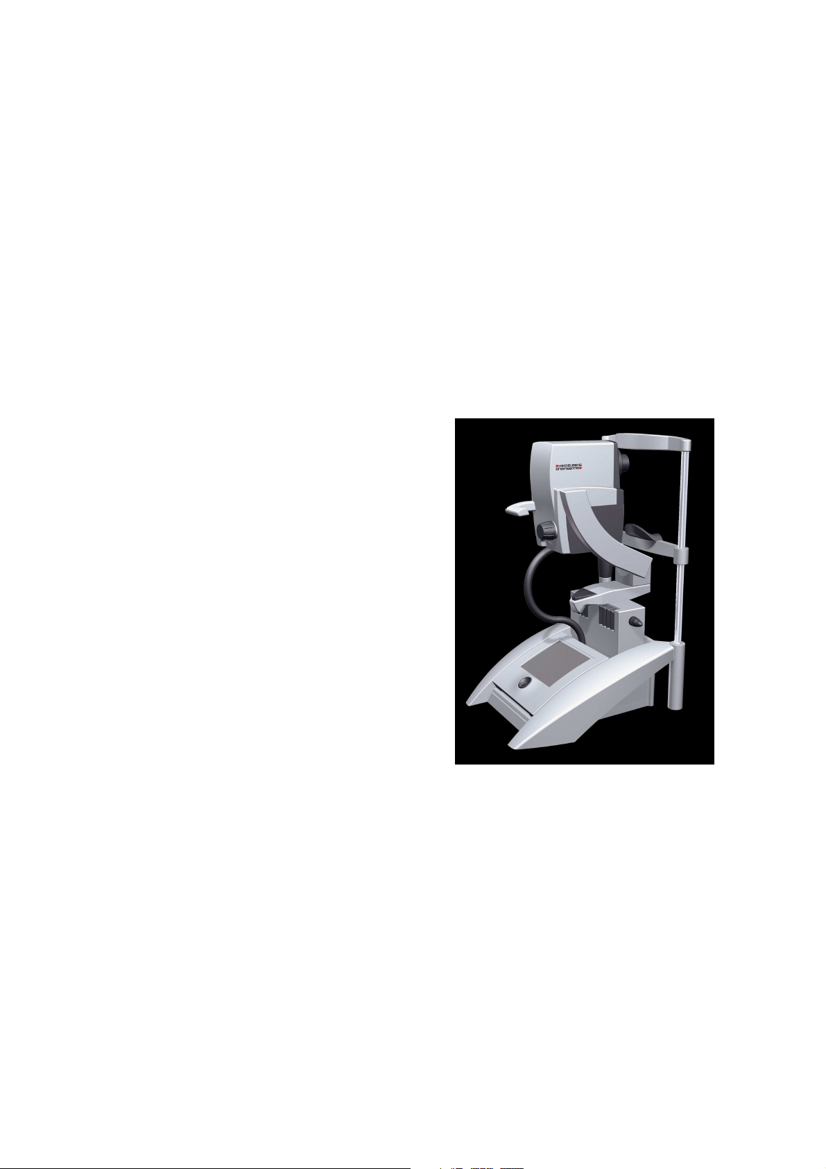
1.2 The Heidelberg Retina Angiograph 2
The Heidelberg Retina Angiograph 2 is a confocal laser scanning system for digital fluorescein
and indocyanine green angiography. Fluorescein and indocyanine green angiography can be performed either separately or simultaneously.
For acquisition of the digital confocal images, a laser beam with a wavelength suitable to excite
the fluorescent dye is focused on the retina. The laser
beam is deflected periodically by means of oscillating
mirrors to sequentially scan a two-dimensional section of the retina. The intensity of the emitted fluorescent light at each point is measured with a light
sensitive detector. In a confocal optical system, light
emitted outside of the adjusted focal plane is suppressed. This suppression increases with the distance
from the focal plane, and results in a high contrast
image. Furthermore (especially during indocyanine
green angiography), the confocal optical system allows the user to acquire three-dimensional images
layer by layer, which is comparable to laser scanning
tomography.
The laser sources contained in the Heidelberg Retina
Angiograph 2 emit laser light of three different wavelengths: for fluorescein angiography, the blue line of
a solid state laser (488 nm) is used to excite the fluorescein. A barrier filter at 500 nm edge wavelength
separates excitation and fluorescent light. The same
wavelength (but without barrier filter) is used to create red free reflectance images. For indocyanine green angiography, a diode laser at 795 nm wavelength is used to excite the dye, while a barrier filter at 810 nm edge wavelength separates excitation and fluorescent light. A second diode
laser at 830 nm wavelength serves to produce infrared reflectance images.
Several image acquisition modes are provided, i.e. pure fluorescein angiography, pure indocyanine green angiography, and simultaneous fluorescein / indocyanine green angiography. In the
simultaneous mode, each image line is scanned twice. During the first scan, fluorescein is excited
and its fluorescence is measured; during the subsequent second scan, indocyanine green is excited
and its fluorescence is measured. In every acquisition mode, individual images, time resolved image sequences, or a focal series of images (layered, three-dimensional images) can be acquired.
The images are immediately digitized with a resolution between 384 x 384 and 1536 x 1536 pixels. The digitized images are stored in the computer's main memory and then saved on the computer's hard disk. The size of the field of view can be set to 15 x 15 degrees, 20 x 20 degrees, or
30 x 30 degrees.
3
Page 8

2 Contraindications, Warnings, Precautions and
Adverse Events
2.1 Contraindications
• Be aware of possible allergic reactions when contrast or dye fluid is injected.
Asked the patient for known allergies and compare it with the contraindications of the
•
contrast or dye fluid.
2.2 Warnings
• Carefully read the instructions for use before operating the device. Misuse of the device
may lead to hazards for patient or user or lead to wrong diagnostic results.
• Do not open the device component housings. Doing so can lead to the possibility of electrical shock and laser radiation. See also subsection “3.4 Instrument Safety” and “3.4.2
Laser Safety”
• Do not use the device outside of the “Intended use” scope. Doing so may lead to malfunctions or damage of the device
• Do not use PCs, components or accessories that have not been approved by Heidelberg
Engineering. Do not install other software programs as they may interfere with the functionality of the Heidelberg Engineering software or equipment. This could include damage to the system as well as incorrect measurement results.
• Do not operate the system without connecting the PC and components to an IEC 60601-1
proven isolation transformer. Doing so could lead to electrical shock to the user and patient in the case of a failure of the PC or to a PC accessory.
• Do not use a network connection without network isolation in accordance to
IEC 60601-1. In case of a failure in the network, there could be a hazard of electrical
shock to the user and patient.
Make sure that the environmental requirements are met when the system is operated. Ex-
•
ceeding environmental conditions might damage the system or lead to wrong measuring
results. (See subsection 7 “Technical Data”).
Make sure the scanners are working (high pitched sound) before installing a patient in
•
front of the device. No laser beam should be visible, when the scanners are off. A hazard
for an injury of the retina would exist if the laser beam hits the retina without being
scanned.
• Make sure the patient is correctly placed in front of the camera before starting the examination. Wrong positioning may lead to poor images and wrong diagnostic results.
Artifacts on the images might falsify the measured results. Do not use the measured re-
•
sults for further treatment if there are artifacts in the images.
• Do make a diagnostic decision on one single examination. Always use alternative
information; history data etc. to assist in a final diagnostic determination.
4
Page 9

• Prepare safeguards to ensure that only authorized personnel can access the patient data.
Data loss impedes follow up analyses and may result in wrong diagnostic decision.
• Be sure to perform periodic data backup procedures. Check the success of the backup to
avoid data losses caused by backup errors.
Do not operate the system directly after obvious climate changes. Let the device accli-
•
mate itself for a minimum of 2 hours to avoid device damage or wrong measurement results.
2.3 Precautions
The operator shall be sure that the device settings and adjustments are correct before ex-
•
amination and diagnostic decision. Wrong settings and adjustments may lead to poor image quality or wrong examination information.
The physician shall be sure to have the correct patient data before a diagnostic decision.
•
Mismatched patient data may lead to wrong diagnostic decisions.
• Read chapter “5.1 Preparation” carefully before starting the examination. Incorrect preparation of the patient may lead to poor image quality and incorrect diagnoses.
• Do not start an examination without informing the patient about the examination procedure. Wrong patient behavior during the examination may lead to poor image quality and
incorrect diagnoses.
• Clean and disinfect chin rest and head rest after each examination. Contaminated parts
may lead to infections or disease contraction.
• Read chapter “7.8 Service, Maintenance and Cleaning” carefully. Missing maintenance or
incorrect adjustment of the device may lead to poor image quality and incorrect diagnoses.
• Do not perform more than 1 examination per day on the same patient. Multiple injections
of the contrast or dye fluid may lead to allergic reactions or shock.
• Before starting the system check the regional power supply specifications to verify that
they fit the required tolerances (100V < U < 240V; 50Hz < f < 60Hz). Wrong power
supply conditions might lead to malfunctions of the system.
• Be aware that the influence of other physical effects (vibrations, strong electromagnetic
fields as caused by big machines etc. running close-by), might disturb the proper operating of the device.
• A computer failure during picture acquisition or analysis could lead to incorrect results.
5
Page 10

3 Installation and Safety Information
3.1 Components of the Instrument
The HRA2 system applies to the applicable standards of IEC 60601-1, IEC 60601-1-2, UL2601,
and IEC 60825.
The basic components of the Heidelberg Retina Angiograph 2 are the:
• Laser scanning camera
• Camera mount with headrest
• Touch panel
• Power supply with Laser module
• Computer
• Isolation Transformer
• Operation software.
The laser scanning camera is the core of the Heidelberg Retina Angiograph 2. It contains the
three-dimensional scanning system, the detector and the main part of the electronics. The solid
state 488nm laser source is located in the laser module and is coupled to the camera via an optical
fiber. The diode lasers for infrared and indocyanine green angiography are located in the laser
scanning camera. The scanning laser beam emerges from the objective on the front of the camera.
The intensity of the emitted fluorescent light is also measured through this objective.
The laser scanning camera is mounted on a special camera mount which also contains the headrest for the patient. The camera mount is designed so that the measuring position on the ocular
fundus can be selected by rotating the camera around two orthogonal axes.
The control panel is used to control image acquisition. Here, the basic image acquisition parameters such as angiography type, laser intensity, detector sensitivity, size of the scanning field and
position of the focal plane are specified. The image acquisition itself is initiated from the control
panel.
The laser module contains one solid state laser. The laser light is transmitted into the laser scanning camera via one fiber optic. The laser scanning camera contains two diode lasers.
The power supply supplies voltage to the laser scanning camera. The on/off switch is located on
the front panel. With the switch in position O, the power supply is turned off.
The Heidelberg Retina Angiograph 2 is operated by a PC-compatible personal computer in combibnation with a IEC 60601-1 proven isolation transformer. The computer receives the image data
generated by the laser scanning camera and performs the entire image analysis. For this purpose,
special hardware is installed in the computer in addition to the Heidelberg Retina Angiograph 2
operation software.
The operation software includes functions to communicate with the user, to control image acquisition, to store images and data, to process and analyze the acquired images, and to document the
examination results.
6
Page 11

3.2 Scope of delivery
The scope of delivery for this instrument consists of the following parts:
Laser scanning camera
•
• Touch panel
Foot switch
•
• Camera mount with integrated headrest
Power supply with Laser module
•
• Frame grabber module for installation in the personal computer
Cable - touch panel to power supply
•
• Cable - frame grabber module to power supply
Cable - frame grabber module to camera
•
• CD containing operation software
Software protector
•
• Operation manual
• Personal computer with hard disk, floppy drive, magneto-optic drive, VGA board, color
monitor, keyboard, mouse, Microsoft Windows 2000/XP operating system.
• Isolation transformer with connector cables.
7
Page 12
eration)
eration)
3.3 Installing the Instrument
(1) Assemble the headrest according to the separate set of instructions. The headrest should be
mounted firmly on the table top.
(2) Place the camera mount onto the sliding platform of the headrest.
(3) Install the frame grabber board into the computer.
(4) Assemble the computer and connect the monitor, keyboard and mouse.
(5) Connect all the power cables (PC, Monitor, Printer and Power Supply) to the isolation
transformer.
Caution:
Do not operate the system without an isolation transformer. Doing so will void the warranty !
It is not allowed to operate PC components in the patients environment without separation via an isolation transformer.
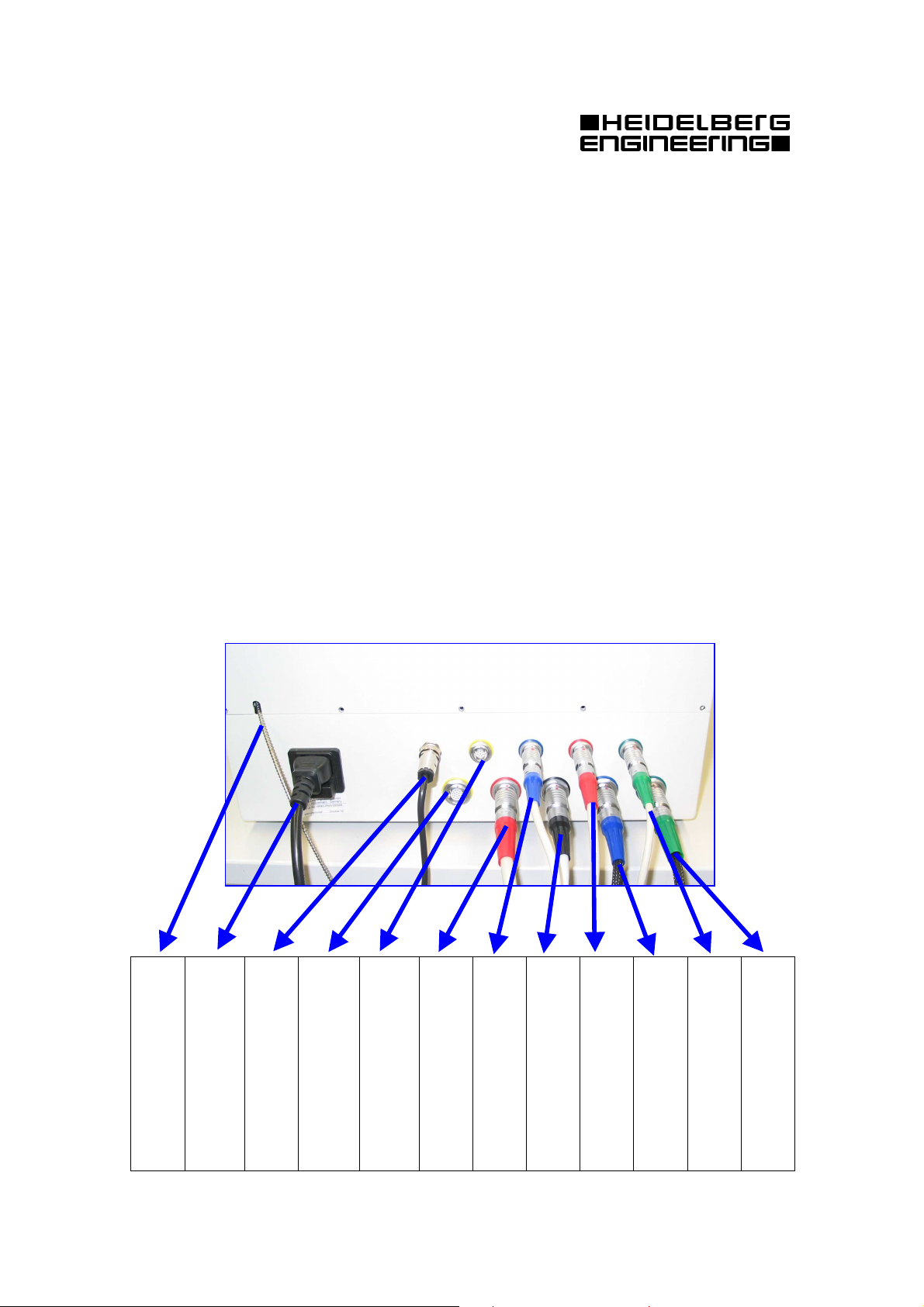
(5) Connect all cables between camera, laser box and PC in accordance to the connection
diagram shown below.
Make sure that all cables are in good condition correctly inserted.
The picture below shows the cable connections to the back of the Laser Box:
camera
Foot Switch
(110 / 230V)
AC- Power Supply
nected to the camera
Metal shielded fiber con-
8
Debug and Service interface
Expansion Interface
Data Cable connected to the
(not connected in normal op-
(not connected in normal op-
nected to camera mount
Left- Right recognition con-
nected to the camera
Touch panel interface
Camera power supply con-
the camera
port (COM1, COM2)
Frame grabber Signals to
Frame Grabber Signals from
RS232 interface to PC-serial
PC- Frame Grabber Board
Page 13

W
ARNING
3.4 Instrument Safety
Important! Before you start working with the instrument, make sure that you know the correct
procedures for turning the instrument on and off (“Chapter 4 General Operating Information”). Do not leave the patient alone with the instrument during the examination.
3.4.1 General Information
The instrument must not be used if there is a mechanical, electrical, or optical defect. Any modifications or additions which are made to the instrument must comply with the relevant legal
guidelines. Any repair, especially of the instrument's electric and electronic systems, and any service work on the instrument components, must only be carried out by appropriately qualified and
authorized staff.
Caution! Unusual noises and/or vibrations may be symptoms of a fault in the instrument.
Please turn the instrument off and contact your local service office. Do not attempt to
repair any faults with the instrument yourself.
3.4.2 Laser Safety
This instrument contains a solid state laser and two diode lasers. The instrument emits visible and
invisible laser light through the objective lens on the front of the laser scanning camera. The Heidelberg Retina Angiograph 2 is a Class 1 laser system. It does not pose any safety hazard whatsoever. The laser class label is located on the rear panel of the camera housing and the rear panel of
the laser module:
LASER CLASS 1
However, hazardous laser radiation may be accessible when the camera housing or the housing of
the laser module is open.
Caution! Never open the housing of the laser scanning camera or the laser module. When the
camera housing or the laser module housing are open, visible and/or invisible laser
radiation of Class IIIB is accessible and can lead to injuries. The camera housing and
laser module housing must only be opened by qualified service staff.
Laser warning labels to this effect are positioned on the cover of the camera housing (underneath
the electronics card which is located there) and on the rear side of the laser module:
LASER BEAM CLASS 3B WHEN
OPEN AVOID DIRECT
EXPOSURE TO BEAM
9
Page 14

To guarantee the safety of the user and the patient at all times, a limit has been imposed on the
maximum period of time for which the laser beam can be switched on. If this limit is exceeded,
the screen shows the message: 'Laser Safety; laser timed out'. Image acquisition is automatically
interrupted and can only be continued after a specified waiting period (about 3 hours). However,
this will not usually occur during normal use of the instrument.
3.5 Care
The Heidelberg Retina Angiograph 2 is a precision optical instrument. Please protect the instrument from dust and moisture, and avoid subjecting it to shocks or strong forces.
The lens surface on the front of the camera should be carefully cleaned at regular intervals (possibly every day). For this purpose, it is best to use acetone and a soft cotton ball.
The non-optical surfaces of the instrument can be cleaned and/or disinfected as usual whenever
necessary. Before doing this, please turn the instrument off and pull out the power plug.
10
Page 15

4 General Operating Information
4.1 Turning the Instrument On and Off
4.1.1 Turning On
To turn the Heidelberg Retina Angiograph 2 on, proceed as follows:
(1) Turn the computer on. After the boot sequence has been completed, the computer will start
the Windows operating system.
(2) Turn on the power supply. The power switch is located on the front panel of the power sup-
ply. The 'off' position is marked O.
(3) Use the Heidelberg Eye Explorer shortcut on the desktop to start the application.
This will start the Heidelberg Eye Explorer software.
Note: It is not recommended to turn the instrument on and off frequently. Even if you are
not using the instrument constantly during the course of a day, it is best to turn it on
in the morning and not to turn it off again until the evening.
4.1.2 Turning Off
To turn the Heidelberg Retina Angiograph 2 off, proceed as follows:
(1) If the acquisition dialog is open and the live image is visible on the screen, stop the image
acquisition with the 'freeze' button on the touch panel and leave the acquisition dialog.
(2) Turn off the power supply. The power switch is located on the front panel of the power sup-
ply. The 'off' position is marked O.
Important! Never turn off the power supply while the laser scanning camera is acquiring im-
ages. This can result in damage to the camera.
Never turn the computer off without quitting the Heidelberg Retina Angiograph 2
operation software first. This can result in the loss of data stored on the computer's hard disk. Before you turn off your computer, select "Shut Down" from
the Windows "Start" menu.
4.2 Controls
4.2.1 Touch Panel
11
Page 16

4.2.1.1 “Freeze” Screen
Immediately after switching on the device.
4.2.1.2 “Freeze” Screen:
HRA2 Acquisition Module started in Eye Explorer. Press button (0) to go to live mode (and
therefore to main screen).
12
Page 17

4.2.1.3 Main Screen
FA/Red Free modes are not available during warm-up (approx. ½ minute).
4.2.1.4 Main Screen
FA laser warmed up. Filter in angiography mode.
13
Page 18

4.2.1.5 Main Screen
FA laser warmed up. Filter in Red Free / IR (reflectance) mode.
4.2.1.6 Target Select Screen
Press button (13) to select this screen. Choose either the external or one of the internal targets. To
switch off all targets, press the button for the selected target again.
14
Page 19

4.2.1.7 Target Select Screen
Central internal target selected. The letters right and left of the internal target buttons show where
the temporal (T) and the nasal (N) side are.
4.2.1.8 Target Select Screen
The T-N letters change whenever the camera head is moved to the other eye.
15
Page 20

4.2.1.9 Main Screen
The selected target is indicated on the select target button.
4.2.1.10 Acquire Mode Screen
Press button (10) on main screen once (twice if not active) to activate this screen. The buttons
marked ‘b’ open a respective screen for selection of the respective parameter.
16
Page 21

4.2.1.11 Select Time for T-Sequence Screen
Press button (16b) to get to this screen. Use +/time series.
( ) *
to change the default time for a
!"
# $
'#
&%
4.2.1.12 Main Screen
The length of the time series is indicated on button (10) now.
17
Page 22

4.2.1.13 Select Depth for Z-Sequence Screen
On this screen the z-scan depth can be changed, similar to the time series before.
4.2.1.14 Select Frames for M-Sequence Screen
Change number of frames that are to be averaged to a mean image.
18
Page 23

4.2.1.15 Main Screen: 3x3 Composite Mode
The current image number is indicated on button (10).
4.2.1.16 Main Screen: 3x3 Composite Mode
After acquisition of one frame the target changes automatically.
19
Page 24

4.2.1.17 Main Screen: 3x3 Composite Mode
Acquisition of last image of the 3x3 composite.
4.2.1.18 Main Screen
After the last 3x3 composite image, the mode changes back to “single” automatically.
20
Page 25

4.2.1.19 Main Screen: Injection Button Pressed
If an angiography mode is selected and no injection timer was started, button (14) will blink.
Press this button to start the injection timer for the current mode. Afterwards, button (14) stops
blinking and stays activated (blue).
4.2.1.20 More Screen
This screen is reached via button (12) on the main screen. Select high speed or high-resolution
mode here.
21
Page 26

4.2.1.21 More Screen
A internal myopic lens can be activated here.
4.2.1.22 Freeze Screen: Interlock
An interlock can be triggered if the FA/red free laser power gets to high or if one or both scanners
do not work properly.
22
Page 27

4.2.2 Foot switch
A
R
The foot switch is used to acquire images. Its function is identical to pressing the ‘Acquire’ button
of the touch panel.
4.2.3 Keyboard
To use the Heidelberg Retina Angiograph 2 operation software, you need the computer keyboard
in order to enter text and to control certain software functions. In the second case, function keys
and special keys are often used. In this operation manual, the function keys are identified as 'F1',
'F2', etc.
4.2.4 Mouse
The Heidelberg Retina Angiograph 2 operation software is controlled via a graphical user interface (menu). For interaction, use your computer's mouse. To select a specific menu field, use the
mouse to move the pointer to the field and press the left mouse button.
4.2.5 Focus knob
The knob at the backside of the camera head changes
the focus. By turning this knob refractive errors of
the patients eye can be compensated for. The current
focus compensation is always shown at the lower left
side of the PC acquisition module screen; units are
diopters.
When examining a patient, set the focus compensation roughly to the patient’s spherical equivalent refraction and then turn the focus knob until you get a
sharp image.
Keep in mind that the refraction for blue and infrared
light differs slightly. Therefore, it is recommended to
readjust the focus compensation when changing from
red free or FA to infrared or ICGA mode or vice
versa.
4.2.6 Filter Lever
By changing the position of this lever at the left side
of the camera head the fluorescence filter is activated
or deactivated. In the position marked by A the fluorescence angiography modes (FA, ICGA) are available, in the position marked by R only reflectance
modes (IR, RF) are available.
23
Page 28

4.2.7 Sensitivity Knob
Turning this knob increases (clockwise) or decreases
(counterclockwise) the light sensitivity of the camera.
Thus by turning the knob the image brightness
changes (high sensitivity = high brightness, low
sensitivity = low brightness).
The current sensitivity value is displayed on the lower
left side of the PC acquisition module screen. Note
that the image begins to blur when the sensitivity is
set to values lower than 40 – 50.
24
Page 29

5 Image Acquisition
5.1 Preparation
5.1.1 Preparing the Patient
No special preparation of the patient is required for an examination with the Heidelberg Retina
Angiograph 2. The image acquisition is possible even without pupil dilation. As a general rule,
however, dilation is recommended to significantly increase the signal-to-noise ratio and therefore
the image quality. Refraction faults are corrected during the image acquisition by moving the focal plane of the system (see below). In case of an astigmatism of more than 2 diopters, glasses or
contact lenses are recommended during the examination.
Prepare the injection of the fluorescent dye. In case of a simultaneous fluorescein and indocyanine angiography, inject both dyes at the same time.
5.1.2 Preparing the Instrument
The startup procedure is described in Chapter 4 “General Operating Information”.
5.2 Image Acquisition
The following is a description of the individual steps required for acquisition with the Heidelberg
Retina Angiograph 2. It is subdivided into the settings required for the computer, the adjustment
of the camera to the eye to be examined, and acquisition of the images.
5.2.1 Creating a new patient record
First, create a new patient record in the Heidelberg Eye Explorer database. As in other Windows
based programs, there a several ways to do that:
1. Using the tool bar
Click with the mouse on the New Patient symbol.
2. Using the menu
Open the menu "Record" and choose item New patient.
A dialog box will appear. Now you can enter the data for the new patient. After that, click on
25
Page 30

"OK" to create the new database record.
For the first time, the fields "Last name", "First name" and "Date of birth" are sufficient. All other
fields may be empty.
After you have created a new patient record, the Heidelberg Eye Explorer will create a new examination, too. This will be explained further in the next step.
If you want to create a new examination for a patient that is already in the database, it is not necessary to re-enter all patient related data. Just select the desired patient and click on the "New Examination" tool bar button,
or press the right mouse button and select "New Examination" from the context pop up menu.
5.2.2 Creating a new examination
The creation of a new examination is the first step after you have entered a new patient. The Heidelberg Eye Explorer is using so called "acquisition modules" to create new examinations with
the different types of ophthalmological acquisition devices. These modules are called "plug-ins",
and can be easily integrated in an existing installation without changing the Heidelberg Eye Ex-
26
Page 31

plorer itself. Thus, it is easy to adapt the Heidelberg Eye Explorer to any new image acquisition
device.
The creation of a new examination starts with the following dialog box:
Choose "Heidelberg Retina Angiograph 2 (HRA 2)" as acquisition device.
After that, the following dialog will appear:
If you want, you can enter the eye parameters for both eyes. Only the cornea curvature will be of
importance, because it will affect the measurement of distances and areas.
5.2.3 Touch Panel Settings and Patient Alignment
(1) The touch panel can now be used to control the image acquisition (see Chapter 4.2.1 “Touch
Panel”). Usually, the following baseline settings for the touch panel are used.
• Select the infrared reflection acquisition mode (press the 'IR' button)
• Set scan angle to 30 degrees (using the 'scan size' button)
(2) Ask the patient to position their head and chin firmly against the headrest and chin rest. The
height of the chin rest should be adjusted so that the eye being examined is located at the
height of the red mark on the headrest. Ask the patient to look straight ahead or to stare at the
fixation target with the eye that is not being examined.
27
Page 32

(3) Adjust the focal plane to the refraction (spherical equivalent) of the examined eye (using the
1 2 3
5
4
6
7
10
11
13
14
15 16
'focus' button on the back of the camera).
(3) On the touch panel, press the 'freeze' button. The selected laser (infrared in the above baseline
setting) will be switched on and the camera will start the image acquisition. If the camera is
operating in simultaneous mode (see touch panel setting), two live images are visible on the
screen. The image types are indicated below the images.
(4) Move the camera (up, down, right or left) to the center of the pupil and adjust the distance
between the front edge of the objective tube and the examined eye to approximately 15 mm.
As soon as the laser beam enters the pupil, you will see an image of the fundus of the eye on
the screen. Now turn the camera on its horizontal and vertical axes so that the structure to be
examined is visible on the screen. Move the camera slightly up/down and sideways until the
image appears brightest.
(5) Then move the focal plane until the image is brightest and set the detector sensitivity (by
turning the sensitivity button on the touch panel) so that you see a bright, but not overexposed
picture. Overexposure causes white areas within the image.
(6) For the fine adjustment of the image, move the camera so that the structure to be examined is
located precisely in the center of the image. Once again, move the camera slightly up/down
and sideways until the image appears brightest. This is the point at which the laser beam falls
directly into the center of the pupil of the examined eye.
5.2.4 Displaying and Changing Acquisition Parameters
During the image acquisition, the following dialog is displayed on the screen:
28
Page 33

Short explanation for the different functions:
1 Save Images:
2 Setup:
3 Exit:
4 Eye:
5 Angle:
6 Focus:
7 Sens.:
8 Mode:
9 Rate :
10 Res.:
11 ICGA:
12 FA:
13 Laser off in:
To store the acquired images to the Heidelberg Eye Explorer
To set up the default resolution and the cyclic buffer size.
To close the acquisition and to return to the Heidelberg Eye Explorer.
Displays the actual eye to be examined.
Displays the actual scan angle.
Displays the actual focus / refraction
Displays the actual detector sensitivity (max. 99 %)
Displays the actual acquisition mode setting (e.g. “Single”)
Displays the actual scan rate of the live image. The scan rate depends on
the scan angle, simultaneous or non-simultaneous acquisition, “high
speed” or “high resolution” mode.
Displays the actual resolution mode. Is either “High Speed” or “High
Res.”
Displays the time that has passed since start of injection timer
Displays the time that has passed since start of injection timer
Displays the actual scan depth (only important when you start series
acquisition. (Depth = 0 is movie acquisition, else 3D-scan
Remaining image acquisition time (seconds) until a 'laser safety timeout'
will occur. The remaining time depends on the current setting of the
scan angle. The image acquisition time is longest when the maximum
scan angle is used.
14 Images:
x MB free:
15 Status line:
16 Laser Mode:
Number of images already acquired into memory
Memory available for new images (in MB)
The bar graphically represents the memory used by the already acquired
images and the remaining free acquisition memory.
Displays important messages to the user. Normal messages are shown in
green, warnings are shown in yellow and errors or other very important
messages are shown in red color.
Displays the actual laser mode of the live image displayed above.
5.2.5 Acquiring Images
(1) It is recommended that some reflectance images be acquired using the infrared or blue reflec-
tance images before injection of the fluorescence dye. It is also recommended that some im-
ages be acquired with the FA mode before injection (auto-fluorescence image). Select the
corresponding acquisition mode with the touch panel (i.e. ‘IR' for infrared reflectance images,
'RF' for blue reflectance images, 'FA' for auto-flourescence images). Press the 'Acquire' but-
ton or use the foot switch to acquire individual images.
(2) Set the laser mode control to the desired position: 'FA' for pure fluorescein angiography,
29
Page 34

'ICGA' for pure indocyanine green angiography, or 'FA&ICGA' for simultaneous fluo-
rescein/indocyanine green angiography.
(3) Set the parameters for image acquisition as follows:
• sensitivity of the detector to 80%
• For pure indocyanine green angiography:
• ICGA laser intensity to 100 %
• For simultaneous fluorescein/indocyanine green angiography:
• ICGA laser intensity to 50% - 75 %
Note: During simultaneous fluorescein/indocyanine green angiography, the intensity of the
indocyanine green fluorescence is usually much brighter for the first 1 to 2 minutes
than the fluorescein. To get the same brightness for both dyes we, therefore, recommend reducing the intensity of the infrared light for the early phase to 50% - 75%.
After 1 or two minutes the laser intensity should be reset to maximum (100 %).
(4) Inject the fluorescent dye(s). Press the 'Inj’ button on the touch panel during or immediately
after injection to start the clocks(s) for the injection time. Please note that the clock(s) will
always be started according to the selected acquisition mode.
(5) Select ‘Single’ or ‘T-Sequence’ on the touch panel if a automated image acquisition of a com-
plete sequence is desired.
(6) Ask the patient not to move. Watch the image on the screen. As soon as you see the first fluo-
rescence, press the 'Acquire' button on the control panel to start the image acquisition.
Note: The Heidelberg Retina Angiograph includes an internal cyclic buffer for live images
acquired during the last 2 seconds (for setting the length of the cyclic buffer, see
Chapter 4.3.1). These images are stored as soon as you hit the 'Acquire' button to initiate the acquisition of a time resolved image series. This ensures that the images of
the last 2 seconds are stored before starting the time series.
(7) The image intensity will vary quickly during the inlet phase of the dye. Watch the image on
the screen. Make sure the camera remains adjusted to the eye and the image brightness does
not approach saturation. Overexposure causes white areas in the image. If necessary, readjust
the image brightness using the 'sensitivity' control on the touch panel.
(8) Watch the number of acquired images in the bottom screen section. An acquisition of a T-
Sequence can be stopped using the 'Stop' button on the touch panel.
(9) Immediately after interrupting the series acquisition, you are able to acquire single images
using the 'Acquire' button again.
(10) Now, acquire individual images by pressing the ‘Acquire’ button on the control panel or the
foot switch. Press the ‘More’ button on the touch panel to change between ‘High resolution’
and ‘High speed’ acquisition if required.
(11) Press the 'freeze' button and select the 'Save Images' menu item to store the acquired images
to hard disk. After the storage procedure, the main memory of the PC is available for acquisi-
tion and you are able to acquire more images.
(12) To acquire a layered three-dimensional image, press on the ‘T-Sequence’ button twice and
select ‘Z-Sequence’ and adjust the scan depth to an appropriate value. The right setting de-
pends on the observed structure. A typical setting is 5 to 6 mm. Now press the 'Acquire' but-
30
Page 35

ton. The system will automatically acquire and store images from 32 equidistant focal planes.
After the acquisition of the focal series, the camera switches back to ‘Single’ mode.
(13) After completing the examination, leave the acquisition module by selecting 'Exit' from the
menu bar. If you have not yet stored all images to hard disk, you will be prompted either to
store or to delete these images.
Note: It is often required to acquire late phase images 30 or more minutes after injecting the
fluorescent dye. During this time, it is possible to examine the early phase of the next
patient. For this purpose, exit the acquisition module (select 'Exit') and proceed as described above to create another patient record using the Heidelberg Eye Explorer. After acquiring the images of the second patient, load the examination of the first patient, switch to the acquisition menu, and continue with the image acquisition. The
clocks for the injection dyes will be automatically set to the right patient and the new
images will be appended to the existing images.
5.3 Image Acquisition Setup
The following setup functions are available inside the acquisition module.
5.3.1 Scan Parameter Setup
Select 'Setup' and 'Scan Parameter' to modify one of the following settings:
Default scan resolution:
High Resolution: Open the acquisition module with max. 1536 x 1536 pixels(at 30°).
High Speed: Open the acquisition module with max. 768 x 768 pixels (at 30°).
Cyclic buffer size (for movies):
After the 'series' button on the control panel has been pressed, the system will take the last 2
sec, 1 sec, 0.5 sec or 0 sec additionally.
5.3.2 Resetting the injection timers
If you want to reset the acquisition timers, e.g. because of a problem while injection, select 'Setup'
and 'Reset Injection Timer(s)'. After that, you can restart the injection timers using the mouse or
the 'I' key on the keyboard.
31
Page 36

6 Image Inspection and Analysis
6.1 Image Viewing
6.1.1 Image Display
To view some of your images in the Heidelberg Eye Explorer Database, change to the Image
View, where you will see all the small “thumbnail” images for every examination.
Double-click on an image icon to open the image in a separate window in its full resolution. You
can also open the context pop up menu using the right mouse button and select the command
"Display":
The following dialog will open in a separate window and will have its own menu and tool bar:
The first four buttons in this tool bar buttons are tools to create overlays on an image. A tool can
be activated by a click on one of the buttons and will be visualized by a slightly modified mouse
cursor. The different tools have the following meaning:
Image Overlays:
32
Page 37

"Text"-Tool allows the creation of small text labels on top of the image. Just click with the
mouse at the desired screen position and enter the text in the dialog box.
"Arrow"-tool allows the user to draw arrows in different colors, sizes and directions. Click
with the mouse at the desired screen position and draw the arrow while you keep the button
pressed.
"Region"-tool allows you to draw a closed outline of an arbitrary shaped region within the
image. Draw the region with the left mouse button and use the right mouse button to auto-
matically close the region.
"Distance"-tool allows the user to measure a distance in millimeters on the image. This will
not work with all types of image data (dependent on the acquisition device). Click on the first
location in the image with the right mouse button. Then release the button and move the
mouse to the second measurement location.
Note: Overlays are stored in addition to the image contents. All overlays can be removed at
any later time. To do that, open the menu "Overlay" and select "Remove all Overlays"!
Zooming:
Scales the image into the original resolution & size.
Scales the image to fit into the actual windows size. The window size can be adjusted with
the mouse as usual.
You can use the "Zoom"-menu to select one of the predefined zoom factors, or just drag a frame
about the area you want to zoom in.
Misc:
Show the previous / next image within the same examination.
Puts the image to the active lightbox.
Deletes the actual image and proceeds automatically to the next image within the same
examination.
Warning! The image will be permanently removed and cannot be recovered!
If necessary, you can open another viewing window, if you want to compare two images on the
screen. The "Windows" menu allows to automatically re-arrange or close all open viewing windows (try "Cascade" or "Tile").
The most important image processing options can be found in the "Image" menu. This menu will
be discussed in the next section.
6.1.2 Image Enhancement
Note: None of the image enhancement tools within the Heidelberg Eye Explorer will change or
modify the original image data. All changes will be stored separately, so they can be undone at any later time. Every time you access an image, the Heidelberg Eye Explorer will
process the appropriate operations on the original image data.
Within the "Image" menu you can find the following enhancement functions:
"Contrast & Brightness"
33
Page 38

"Sharpen" to enhance small image details
"Noise Reduction" to enhance noisy images
Each function will open the following small dialog box. It has three tabs, one for each of the functions mentioned above. Within each tab you can set the parameters for the operation.
Contrast and brightness can be adjusted simultaneously using the red square. Just use the mouse
to move the red square within the gray rectangle. You will quickly get a feeling on how the
movement of the red square will affect the image. Alternatively you can enter two values (percentage) for contrast and brightness.
There are 4 different settings for "Sharpen" and "Noise Reduction", starting with "None" (default)
to "High".
Click on the "Close" button to close the image enhancement dialog.
6.1.3 Movie Display
Double-click on a movie icon to play back the movie in a separate window in its full resolution.
You can also open the context pop up menu using the right mouse button and select the command
"Display":
The following dialog will opening in a separate window with its own menu and tool bar:
34
Page 39

The toolbar at the bottom of the dialog is self-explanatory (i.e. Play, Pause, Stop, Jump to Start,
Previous Image, Next Image, Jump to End)
Puts the actual image to the active lightbox.
Export as AVI:
Use menu "Movie" and select "Export as AVI..." to export the complete movie in the standard
AVI file format.
Changing Play-Back image rate:
You can also change the play-back speed of the movie display using menu "Movie" and selection
"xx frames per second". This enables you to play back the movie in higher speed or slow motion.
Play back with eye movement correction:
If the movie images have already been aligned (see section "Image processing" on how to do
that), you can play back the movie without eye movements. Use "Movie" and select "Eye Movement Correction" to enable this feature.
6.1.4 Expanding a Movie
If you would like to access all the images within a movie object, you can use the "Expand" command from the context menu to show up all single images:
Now you can work with the single images of the movie as with all other images on the top level
(e.g. you can put images to the lightbox).
35
Page 40

If you would like to close an expanded movie, use the small "directory up" button shown beside
"OD" or "OS:
6.2 Image Processing
6.2.1 Computing Composite Images
The software is able to automatically combine an unlimited number of images to a single wide
angle image composite. You can apply this operation directly on a movie symbol, or an arbitrary
selection of single images.
After you have selected the images, choose 'Compute Composite' from the right mouse button
context menu to start the automatic computation of the composite image. Please be patient, depending on the number of selected images and on the performance of your computer system, the
image processing may take up to several minutes,
When the calculation is ready, the software will display the resulting image and will appended
this image at the end of the examination.
If you want to remove all source images after computation of the composite, it is necessary to
compute the composite images before you archive the image data for this examination.
To acquire the images, it is recommended to set the image frame rate to 2 imgs/sec (using the '+'
and '-' keys while the live image is on screen). To start the image acquisition, press the 'series'
button on the control panel. While the camera is taking images (two per second), move the camera over the retina. The following moving pattern is recommended:
36
Page 41

Start horizontally centered in the periphery. Swing the camera head downwards and upwards. Return back to the middle position. Go to the right. Again swing the camera downwards and upwards, etc.
Proceed until you covered the whole area of interest. Stop the acquisition of images by pressing
the 'freeze' button on the control panel. A reasonable value for the number of acquired images for
the composite image is 30 up to 100.
You are not restricted to this moving pattern. After you've got some experience with this kind of
acquisition, you will find the most suitable pattern for your needs.
Important: To obtain an image series suitable for the mosaic computation, it is important to
avoid any movements of the camera mounting base or any adjustments of the height
of the camera.
6.2.2 Computing Mean Images
To compute a mean image of several single images, select the images as described above and
choose 'Compute Mean Image':
After the averaging procedure, the resulting image is appended at the end of the examination.
Averaging makes sense for images with a low signal to noise ratio, e.g. auto-flourescence images,
late phase images or images of cataract patients. The signal to noise ratio increases by a factor of
n
, where n is the number of images to be averaged (e.g. factor of 2 (for n=2) and factor of 4 (for
n=16)). Because of this mathematical fact, using more then 16 images will only slightly enhance
the resulting mean image quality.
37
Page 42

6.2.3 Eye Movement Correction
To compute the eye movements within an angiographic sequence (movie), select the images as
described in "Compute Composite Images" and select "Align Movie" or "Align Images" from the
right mouse button menu:
After the alignment procedure, the computed eye movements will be stored to the movie, so it
needs to be determined only once for every movie. When you playback the movie ("Display" or
double-click), you can enable the "eye movement correction" from the "movie" menu.
Note: The alignment of the images (translation and rotation) will cause a movement of the im-
age borders.
6.3 Printing
To print images on an attached printer, select the desired images in the image view using the
mouse. The selection of multiple images works as you are used to do it with the Windows® file
explorer (Please refer to the Heidelberg Eye Explorer ):
A single click with the left mouse button selects one image.
You can select multiple images if you keep the "Ctrl" key on the keyboard pressed while you
select the images with the left mouse button.
Draw a rectangular frame around the images to be selected.
Press the right mouse button to open the context pop up menu and select item "Print".
The upper part of the print dialog shows drop-down list with all installed printers. In the lower
38
Page 43

part, you can define, how many images will be printed on each page (field "Number of Images
per Page").
The Heidelberg Eye Explorer offers three types of print reports:
Standard Report: Prints the header, footer and patient data.
Anonymous Report: Prints the header, footer, but no patient data.
Blank Report: Neither header and footer, nor patient data will be printed.
Click on the button "Customize header and footer of printout" to personalize the header and
footer region.
You can define several file paths to your own bitmap files (BMP), which shell be printed in the
header and footer region of the report. This can be used to put personal information like text and
logos on the printout.
To create files in BMP format, you can use the program "Paint" which can be found in the Windows® 95/98/NT accessories.
39
Page 44

7 Technical Data
7.1 Model Type and Manufacturer
Model Type: Heidelberg Retina Angiograph 2 (HRA2)
Manufacturer: Heidelberg Engineering GmbH
Gerhart-Hauptmann-Strasse 30
69221 Dossenheim / Germany
7.2 Environmental Specifications
Environmental Specification Operating Non Operating
Temperature 10°C to 40°C / 50°F to 104°F -30°C to 60°C / -22F to 140F
Rel. Humidity 10% to 90% 10% to 100%
7.3 Power Supply and fuses
Specification Tolerances
Input Voltage 100V to 240V.
Frequency 50Hz to 60Hz
Fuse 230V 1,25AT
Fuse 110V 2,5AT
HRA2 power consumption 70 W
PC components See technical specifications for
the PC- components
40
Page 45

7.4 Isolation Transformer for PC- components
The isolation transformer has to be certified in accordance to the IEC 60601-1 and / or UL2601
standard.
Voltage / Manufacturer Type / Capacity
230V / DEMETEC GmbH IPs630K (630 VA)
110V / Tsi Power Corporation ILC-1000 (1000W)
7.5 Laser Source
Laser Specification
ICG excitation Diod3e Laser 790nm, Laser Class 1
IR reflectance Diode Laser 820nm Laser Class 1
FA excitation and blue
reflectance
Solid state Laser 488nm Laser Class 1
41
Page 46

7.6 Scanning Specifications
Function Specification
Field of view: 30°x30°, 20°x20°, 15°x15°, wide field compos-
Focus Range -12 to +12 diopters spherical, increments of
ite image to 120°
0,25dpt.
High Resolution Mode:
Scan Size 30°x30°, 20°x20°, 15°x15°
Digitized Image Size (Pixels) 1536x1536, 1024x1024, 768x768
Max. Image Frequency 5 Hz, 7 Hz, 9 Hz
Scan Time/Image 96ms to192 ms
Digital Resolution 5µm/pixel
Z-Scan Depth Max. 8mm
High Speed Mode
Scan Size 30°x30°, 20°x20°, 15°x15°
Digitized Image Size (Pixels) 768x768, 512x512, 384x384
Max. Image Frequency (single) 9Hz, 12,5Hz, 16Hz
Max. Image Frequency (pairs) 5Hz, 7Hz, 9Hz
42
Scan Time/Image 48ms to 96ms
Digital Resolution 10µm/pixel
Z-Scan Depth Max. 8mm
Page 47

7.7 PC Requirements
Operating System Windows 2000 professional or Windows XP professional
Processor 2 GHz Intel Pentium or AMD Processor
RAM 512 MB (or more)
VGA Board High performance VGA board (with DVI interface for 1600x1200 resolu-
tion in case of a TFT monitor. E.g. ATI Radeon 8500)
Framegrabber HE framegrabber (same as for HRT II system), requires 1 PCI slot
Ports 2 serial COM ports required (1 for normal operation, one for debugging)
Hard disk controller IEE1394 (Firewire / I-link) interface controller
Internal hard disk 40 GB hard disk (for operating system and HRA 2 software only!)
Patient data storage external firewire hard disk (> 200 GB)
Archive data storage 2nd external firewire hard disk (same size as data disk)
Monitor:
Technology TFT (recommended), connected by DVI:
• 19 “ Iiyama AU 4831D
• 20 “ Viewsonic VP 201m
CRT:
• 21 “ high quality monitor
Resolution 1600 x 1200 pixels required (the acquisition software will not start up
with a smaller resolution!)
7.8 Service, Maintenance and Cleaning
• Please be aware that authorized service personnel only can do Service and Repair operations of the HRA2. So do not open the device. You will lose the warranty. If the device
fails please call your local distributor or the Heidelberg Engineering support department.
• The Heidelberg Retina Angiograph 2 is a precision optical measuring instrument. Protect
the instrument against dust and moisture, and avoid shocks and the action of strong
forces.
• The inclined glass plate on the front of the camera’s objective lens should be carefully
cleaned at regular intervals. For this purpose, it is best to use acetone and a soft cotton
ball.
• The non-optical surfaces of the instrument can be cleaned and/or disinfected as usual
whenever necessary. Before doing this, turn the instrument off and pull the power plug
out.
• A yearly inspection of the device by a Heidelberg Engineering Service unit is highly
recommended to grant proper and exact operating.
43
Page 48

Type Label on the
Serial n
u
mber
Serial n
u
mber
Serial n
u
mber
Serial n
u
mber
Serial n
u
mber
Fuses to be used in
Attention be aware
7.9 Labels
Heidelberg Engine ering GmbH
6922 1 Dossenheim, Germany
Serial No: ......... HRA2-000010
Manufactured: ..........March 03
Heidelberg Engine ering GmbH
6922 1 Dossenheim, Germany
Serial No: HRA2-MNT-000010
Manufactured: ..........March 03
Heidelberg Engine ering GmbH
6922 1 Dossenheim, Germany
Serial No: . HRA2-TSP-000010
Manufactured: ..........March 03
Heidelberg Engine ering GmbH
6922 1 Dossenheim, Germany
Serial No: HRA2-PWS-000010
Manufactured: ..........March 03
Heidelberg Engine ering GmbH
6922 1 Dossenheim, Germany
Serial No: . HRA2-SLU-000010
Manufactured: ..........March 03
Camera
Headrest
Touch panel
Power supply
Sapphire-
Laser unit
Heidelberg Engineering GmbH
69221 Dossenheim, Germany
Model: ............................. PS410
100-240 V~ 50-60 Hz 70 W
230 V~ : 2x T 1.25 A / 250 V
110 V~ : 2x T 2.50 A / 250 V
Power Supply /
Laser unit
Maximum Power
Consumption
Application Part
Type B
44
the Laser Box /
Power Supply
of the Instructions
for Use
Page 49

UL- Label on the
Warning Label on
CFR compliance
W
ARNING
Laser Class 1
Heidelberg Retina Angiograph 2 / HRA 2
WITH RESPECT TO ELECTRIC SHOCK
FIRE, AND MECHANICAL HAZARDS ONLY
IN ACCORDANCE WITH:
UL2601-1/CAN/CSA C22.2 No. 601.1 and IEC 60825
XXXX
Power Supply /
Laser unit
LASER BEAM CLASS 3B WHEN
OPEN AVOID DIRECT
EXPOSURE TO BEAM
the Power Supply /
Laser unit
This product conforms to the
applicable requirements of
21 CFR Subchapter J at the
date of manufacture.
LASER CLASS 1
Label on the camera
label on the
Camera
45
Page 50

A
Reflexion
-
Mode
Angiography
-
Sensitivity a
d-
justment Touch
R
Filter on the
Camera
Screen
7.10 Disposal
Only Heidelberg Engineering shall dispose the device.
Mode Filter on
the Camera
Focus Function
on the Camera
46
 Loading...