

Page 1

Heidelberg Edge Perimeter
Installation and
System Configuration
Version 002, November 2010
© Heidelberg Engineering GmbH 2010
Art. No. 90922
QM-No. 97 251-002
Page 2

2
The manufacturer hereby declares that this product conforms to the requirements
0482
of Directive 93/42/EEC of the Council of the European Community dated 14 June
1993 regarding medical products (MDD 93/42/EEC).
Corporate Headquarters
Heidelberg Engineering GmbH • Tiergartenstr. 15 • 69121 Heidelberg • Germany
Phone +49 6221 6463-0 • Fax +49 6221 646362 • www.HeidelbergEngineering.de
US Main Office
Heidelberg Engineering, Inc. • 1499 Poinsettia Avenue, Suite 160 • Vista, CA 92081
Phone 760 598-3770 • Fax 760 598-3060 • www.HeidelbergEngineering.com
US Service Center
Heidelberg Engineering, Inc. • 410 Harris Road • Smithfield, RI 02917
Phone 401 349-0500 • Fax 401 349-0504 • www.HeidelbergEngineering.com
Page 3

3
Table of Contents
Table of Contents
Table of ContentsTable of Contents
1111 GENERAL INFORMATION
GENERAL INFORMATION................................
GENERAL INFORMATIONGENERAL INFORMATION
................................................................
................................................................
................................................................
................................................................
................................................................
................................................................
................................ 4444
................................................................
1.1 T
1.2 T
1.3 R
1.4 T
1.5 S
1.6 M
2222 HARDWARE INSTALLATIO
2.1 U
2.2 I
2.3 S
2.4 P
2.5 T
3333 OOOOPERATING SOFTWARE IN
3.1 O
4444 INSTALLATION INSTRUC
HE MEDICAL DEVICE
HE
HEP S
YSTEM
EGULATORY STANDARDS
HIRD PARTY HARDWARE AND SOFTWARE
AFETY INFORMATION, CAUTIONS AND WARNINGS
AINTENANCE
HARDWARE INSTALLATIONNNN ................................
HARDWARE INSTALLATIOHARDWARE INSTALLATIO
NPACKING THE
NSTALLING THE EXTERNAL
ETTING UP CABLE CONNECTIONS
OWER-UP SEQUENCE
RANSPORTATION INSTRUCTIONS
PERATING SOFTWARE INSTALLATION
PERATING SOFTWARE INPERATING SOFTWARE IN
PERATING SOFTWARE - UPDATE
INSTALLATION INSTRUCTIONS FOR SHARING DA
INSTALLATION INSTRUCINSTALLATION INSTRUC
HEP........................................................................................................................................4
..........................................................................................................................................................5
...........................................................................................................................................5
.............................................................................................................5
..............................................................................................................................................................8
................................................................
................................................................
HEP...................................................................................................................................................9
TFT M
ONITOR
......................................................................................................................... 12
:............................................................................................................................................... 13
:.......................................................................................................................... 13
STALLATION ................................
STALLATIONSTALLATION
........................................................................................................................... 14
TIONS FOR SHARING DATABASES BETWEEN
TIONS FOR SHARING DATIONS FOR SHARING DA
.......................................................................................................... 11
.............................................................................................7
................................................................
................................................................
................................................................
................................................................
TABASES BETWEEN HRT AND HEP
TABASES BETWEEN TABASES BETWEEN
..........................................................
................................................................
................................................................
................................................................
HRT AND HEP.......
HRT AND HEPHRT AND HEP
..........................9999
....................................................
................................ 14
................................................................
14
1414
....... 17
17
..............
1717
Page 4
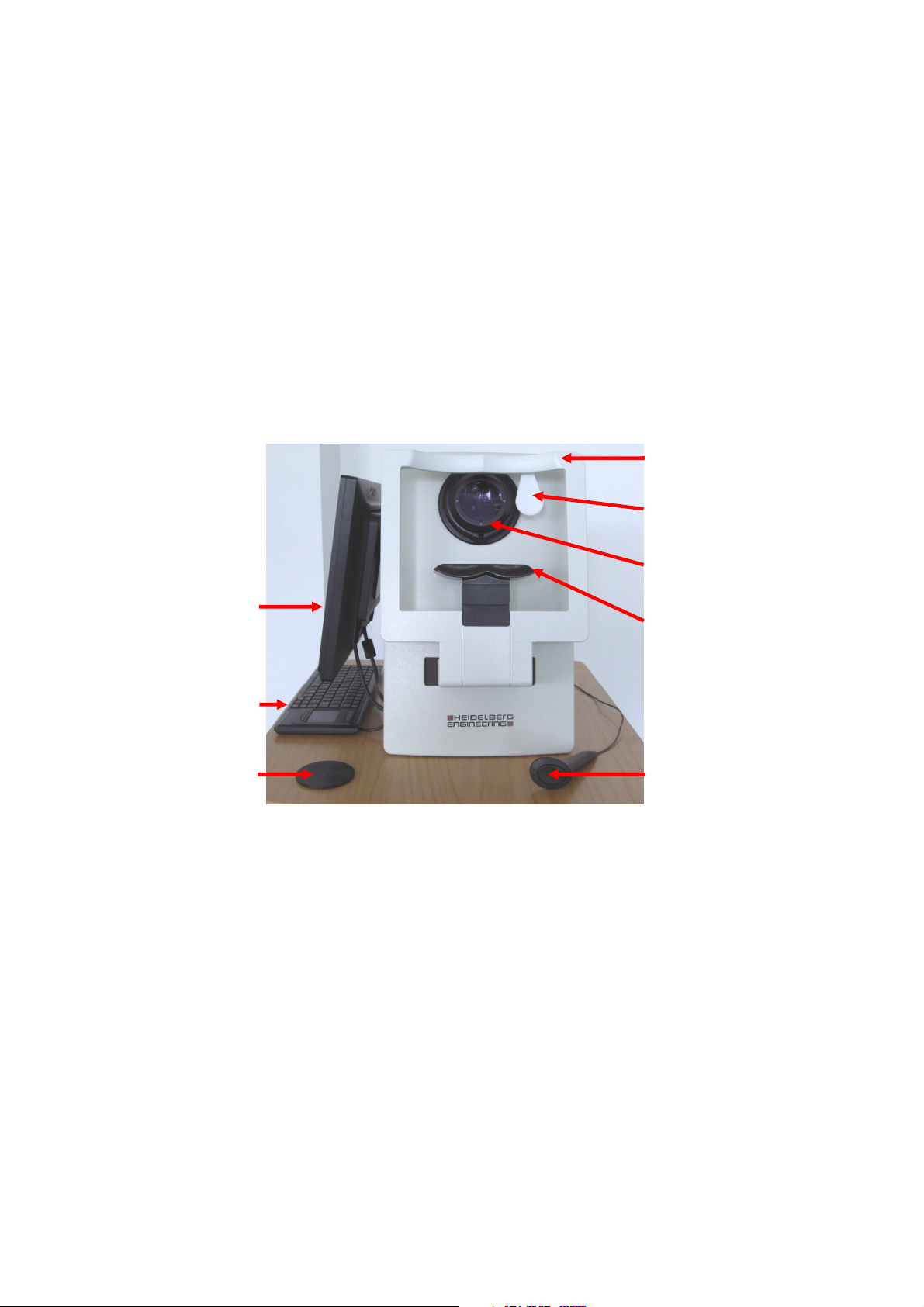
4
17” monitor
Lens cover
Chin rest
Lens
Eye occluder
1 General Information
1.1 The Medical Device HEP
The Heidelberg Edge Perimeter (HEP) is designed to provide comprehensive functional testing of the
visual system. It employs traditional visual field measurement techniques such as Standard Automated
Perimetry (SAP), along with a unique new visual function-specific stimulus called Flicker-Defined
Form (FDF). This enables full scope perimetric evaluation of patients with retinal, optic nerve and
neurological defects. The FDF stimulus is specifically designed for the early detection of glaucomatous
visual field changes.
Standard Automated Perimetry (SAP) may be considered more suitable for the detection and
monitoring of neurological defects, moderate to severe glaucoma and other conditions associated with
extensive and deep visual field loss, such as ischemic optic neuropathy.
Head rest
Keyboard
Patient Response
Button
Page 5

5
1.2 The HEP System
The HEP can work alone as a stand-alone perimeter or in combination with the Heidelberg Retina
Tomograph (Model HRT 2 or 3 with software version 3.1 or higher) for a comprehensive glaucoma
analysis of structure and function.
The HEP alone and together with other connected devices constitutes a medical electrical system (“ME
system”) according to IEC 60601-1-1. This system must meet specific safety criteria as detailed in the
standard and in this document. Note that every connected device will become part of the ME-System even if the
only connection is the power supply cord leading to a shared multiple socket outlet.
WARNING
For setting up a safe system it is essential to read and understand the below section Safety
Information.
The ME system may only be assembled by qualified personnel with training and
knowledge in electrical safety, heeding all instructions and safety warnings contained
in this document. It is especially important that all users that de-install and reinstall
the system (for example in a mobile use scheme) are trained to do this in a safe way.
1.3 Regulatory Standards
The HEP complies with the international IEC 60601 standard series concerning medical electrical
equipment. These standards are published by the International Electrotechnical Commission and are
the base of most national and regional standards for medical electrical equipment worldwide.
Some local standards contain deviations from the IEC versions. These standards include UL 60601-1
(USA), CAN/CSA C22.2 No. 601.1 (Canada), JIS T 0601-1 (Japan), AS 3200.1.0. (Australia) and others.
Wherever IEC 60601-Standards are mentioned inside this document, the according regulations of respective local
standards are also implied.
NOTICE
Even though the HEP already conforms to most local standards for medical devices in
its default configuration, actual conformance can only be ensured by buying it from an
authorized local Heidelberg Engineering distributor.
1.4 Third Party Hardware and Software
1.4.1 Isolation Transformer
HEP device, TFT monitor and all mains supplied accessories need to be supplied through an isolation
transformer:
• Noratel Germany AG, model: IMEDi 300WR (300 VA) or
• DeMeTec, Germany, type IPS (330 VA)
Make sure that the total power consumption does not exceed the specified electrical power output for
each individual isolation transformer as indicated above.
Page 6

6
1.4.2 Printers
The HEP device can be operated with any standard inkjet printer.
To ensure safe operation, please note that they must have CE and/or FCC approval.
1.4.3 External Devices
The HEP device can be operated with the following external devices:
• USB hub
• USB storage device
• External DVD-RAM drive
To ensure safe operation, please note:
• USB hub and storage device must have CE and/or FCC approval.
• USB hub and storage device must be powered from USB port only.
1.4.4 Anti-virus Software
Use the HEP device exclusively with AVG antivirus software. Other antivirus software may interfere
with FDF stimulus presentation.
When installing the antivirus software per manufacturer’s recommendation, configure it so it does not
scan automatically. Otherwise it may interrupt the operation of the device.
Page 7

7
1.5 Safety Information, Cautions and Warnings
This section contains important safety information. Please read it carefully!
1.5.1 General Safety Information
IMPORTANT Before you start working with the instrument, make sure that you know the correct
procedures for turning the instrument on and off (see HEP Operation Instructions).
IMPORTANT Carefully read the instructions for use before operating the device. Misuse of the device
may lead to hazards for the patient or the operator or can lead to wrong diagnostic
results. Use outside the “intended use” scope may also lead to instrument damage.
The instrument must not be used if there is a mechanical, electrical, or optical defect. Modifications or
additions lead to loss of conformity. Heidelberg Engineering does not take responsibility for modified
HEP devices.
Any repair, especially of the instrument's electric and electronic systems, and any service work on the
instrument components, must only be carried out by Heidelberg Engineering or an authorized
distributor.
1.5.2 Warnings and Cautions
WARNING
To avoid the risk of electric shock, the system must be installed in accordance to IEC
60601-1-1 or the corresponding local standard particularly with regard to the electrical
leakage currents. Every modification to the system requires a new evaluation of the
requirements of said standard.
WARNING
If your system configuration includes a multiple socket outlet, do not place it on the
floor as this entails the risk of liquid ingress or accidental mechanical damage.
WARNING
Do not connect an additional multiple socket outlet or an extension cable to the
system. This would lead to increased protective earth impedance and therefore to an
increased risk of electric shock.
WARNING
Do not connect additional devices to the system that are not part of the system or not
specified as compatible to the system.
WARNING
Do not use multiple socket outlets that are part of the HEP system for other devices
that are not part of the system (e.g. office equipment, domestic appliances). This would
lead to increased electrical leakage currents and therefore to an increased risk of
electric shock for both patient and operator.
WARNING
Devices intended to be used together with a separating transformer (or ‘isolating
transformer’) may not be used without that transformer. A bypass of the separating
transformer may lead to excessive electrical leakage currents and therefore to an
increased risk of electric shock.
WARNING
Do not touch the patient and parts inside access covers or contacts of connectors of
nonmedical devices simultaneously.
WARNING
Carry out all cleaning, adjustment, sterilization and disinfection procedures as
specified in the enclosed instructions for use of the particular system components.
Page 8

8
Refraining from that may lead to infections or to bad measurement results that again
may lead to a false diagnosis.
If a multiple socket outlet is used as part of the system, it must conform to IEC 60601-1-1, in particular
it must only allow connection of power cords by using a tool.
All parts of the system can be used inside the patient environment if the requirements defined in this
document and in the according standards are met.
For instructions for cleaning and permissible environmental conditions, see the enclosed instructions
for use of the particular system component.
1.6 Maintenance
For details on cleaning and maintenance, please refer to the HEP Operation Instructions.
Page 9

9
2 Hardware Installation
Accessories, i.e. cables, external
Heidelberg Edge Perimeter
2.1 Unpacking the HEP
Carefully open the HEP box (view from the top):
monitor, operating instructions
Remove the box on the left with the HEP accessories (monitor, cables).
Remove the top foam cover:
Page 10

10
Take the whole HEP system out of the box and place it on a plane surface.
Make sure you always pick up the HEP placing your hands around the bottom of the instrument.
Note:
Note: Be careful to never lift the HEP at its chin rest (left image) nor at its head rest (right image).
Note: Note:
Page 11

11
2.2 Installing the External TFT Monitor
Monitor mount with hexagon
The external TFT Monitor is part of the HEP accessories. The monitor can be mounted on either side of
the instrument, depending on the practice’s or clinic’s facilities.
After slightly unscrewing two hexagon sockets, the monitor mount position may be changed. After
adjustment, refasten the hexagon sockets again.
sockets
The mount counterpart can be found at the back of the monitor. The monitor can easily be hooked up
at the HEP.
Page 12

12
4 USB ports
DVI port for 17”
Power push
1x IEEE1394
Serial port for patient
Power inlet
Microsoft label
Serial number
Type label
Monitor mount counterpart
DVI cable
connection
Power cord plug
2 x Ethernet ports
2.2.1 Isolating Transformer
Connect the low heat devices i.e. HEP system, the height adjustable table and printer (if applicable) to
the isolating transformer using the cables for low heat devices.
Connect the power cable to the isolating transformer. Do not connect the power cable to the mains yet.
2.3 Setting up Cable Connections
Open the cover on the backside of the HEP instrument.
operator monitor
response button
Connect the DVI monitor cable, the patient response button, the keyboard, the mouse if not using a
touchpad on the keyboard and the main power cable.
Attach the power cord to the power socket.
button
Page 13

13
The bottom plate of the HEP contains two holes. The following cables can be guided through these
holes from underneath the HEP: keyboard, mouse, patient response button, DVI monitor cable.
Note: Make sure the instrument is not accidently placed on a cable.
2.4 Power-up Sequence:
1) Turn on the external 17” monitor.
2) Turn on the HEP by pressing the power push button for several seconds until you hear the computer
starting up.
Note: The external monitor must always be turned on before the HEP. If the HEP is turned on while
the external 17” monitor is off, the Windows operating system will automatically select the
internal CRT monitor as primary display and not extend the desktop to the external monitor.
In such a case, please disconnect and then reconnect the power cord at the back of the HEP and
follow the proper power-up sequence described above.
After software installation (see below), attach the USB software protector (dongle) to the back of the
HEP instrument and close the instrument back with the cover.
2.5 Transportation Instructions:
When transporting the HEP the instrument must be packaged in the original packaging material. To
pack up the HEP, repeat the steps 2.1 to 2.4 in reverse order.
Page 14

14
3 Operating Software Installation
To install the software for the Heidelberg Edge Perimeter, insert the USB key delivered with the
instrument into the USB-drive at the back of the HEP and wait for the automatic startup of the
installation program or manually run the “setup.exe” program from the root directory of the USB key.
Note: To avoid virus infection of the HEP, the USB key delivered with the HEP must not be inserted in
any other instrument or computer but the HEP.
3.1 Operating Software - Update
In case of a software update (i.e. an older version of the Heidelberg Edge Perimeter software is already
installed on the system), plug a virus-free USB memory stick containing the update software into one
of the four USB ports in the back of the HEP instrument. Note that one port will already be occupied by
the USB keyboard.
If no window appears showing the USB memory stick’s contents automatically, open it by double
clicking the My Computer icon located in the top left corner of the Desktop. Then double click the
Removable Disk (D:)
Double click the installer program to start the
installation process. When the FDF Update
window appears, click the Next button.
(D:) icon near the bottom of the window.
(D:)(D:)
Page 15

15
When the Ready to Install dialog appears,
click the Next button.
When the installer completes the update
procedure, click the Finish button, and remove
the USB memory device.
3.1.1 Update Verification
Start the Heyex by double clicking on the Heidelberg Eye Explorer icon located along the left side of the
desktop.
Open the Options dialog by selecting the Setup menu, then selecting the Options menu item.
Page 16

16
Select the Plugins tab of the Options window and verify that the FDFAcquire and FDFViewer modules
have the version numbers indicated by the received update information.
If the versions are not listed with the correct values, please contact Heidelberg Engineering for
assistance.
Page 17

17
4 Installation Instructions for Sharing
Databases
between HRT and HEP
This instruction explains how to connect a new Heidelberg Engineering instrument (for example HEP)
to the HEYEX database of an existing Heidelberg Engineering instrument (for example HRT).
Terminology:
Terminology:
Terminology:Terminology:
Instrument A = computer of the existing instrument
Instrument B = computer of the new instrument to be added
Configuration Assumptions:
Configuration Assumptions:
Configuration Assumptions:Configuration Assumptions:
It is assumed that the newly added instrument (Instrument B) has no existing patient data and
therefore no database merging will be necessary. Instead, instrument B will be pointed to the database
of the existing instrument (Instrument A). Consequently, both instruments will be writing to and
reading from the same database on instrument A.
Furthermore, it is assumed that the database resides on the local drive of the existing instrument A and
will remain there. The two instruments are networked via a cross-over cable.
WARNING
Preparation
Preparation
PreparationPreparation
Before you start:
• Connect both instruments with an ethernet cross-over cable (X-over network cable with RJ45
connectors; 2 meters)
• Start both instrument’s computers
• Remove the software protector dongle from instrument B. Ensure that the image acquisition
licenses for both instruments as well as all viewing licenses have been configured for the software
protector dongle on instrument A.
• Remove shortcut to Heidelberg license manager from auto start on the instrument B (start > All
Programs > Startup > Right click on Helic > delete)
The combination of HEP and HRT must conform to the medical safety standards;
in particular the leakage currents must be within respective limits specified by the
international standards. To achieve this we strongly recommend using a network
isolator when connecting the two systems.
Step 1. Adding instruments to a workgr
Step 1. Adding instruments to a workgroup
Step 1. Adding instruments to a workgrStep 1. Adding instruments to a workgr
Do the following on both instruments:
Start > Control Panel > System > Tab “Computer Name” > click “Change” button > select “Workgroup”
option under “Member of” > enter name of the workgroup (use same workgroup names for both
instruments).
oup
oupoup
Page 18

18
Step 2. Ass
Step 2. Assigning identical username and password
Step 2. AssStep 2. Ass
The username and password for both instrument’s PC need to be identical. Make sure you insert a
password as Windows XP is not allowing empty passwords.
Do the following on both instruments:
Select Start > Control Panel > User Accounts > double click on User > enter Username (use the same
username for both instruments) > click OK > while same user is still selected click Reset password >
enter new password and confirm new password (use the same password for both instruments)
Step 3. Assigning IP Address
Step 3. Assigning IP Address
Step 3. Assigning IP AddressStep 3. Assigning IP Address
Do the following on both instruments:
Select Start > Control Panel > Network Connections > Right click on Local Area Connection > Properties >
select Internet Protocol TCP/IP > click Properties > select Use the following IP address > Enter IP address
(use different IP addresses for each instrument)
Now restart both instruments’ computers
Step 4. Sharing the data and patient folder on instrument A
Step 4. Sharing the data and patient folder on instrument A
Step 4. Sharing the data and patient folder on instrument AStep 4. Sharing the data and patient folder on instrument A
igning identical username and password
igning identical username and passwordigning identical username and password
The data and patients drive on instrument A need to be shared in order to allow instrument B to access
these folders.
4a) File Sharing for Windows 2003 and below
4a) File Sharing for Windows 2003 and below
4a) File Sharing for Windows 2003 and below4a) File Sharing for Windows 2003 and below
1. Double click on My Computer on Instrument A
2. Select the instrument’s data drive
3. Right-click on the Data folder and select Sharing and Security from the menu
4. In the Properties
window click on the Sharing tab
5. Select the radio button Share this folder
6. Click on New Share
Page 19

19
7. In the New Share
8. Click the Permissions button
9. In the Permissions for
then click to place a check mark in the Allow Full Control box.
window name the share “Data”
window group or user names dialog window click once on Everyone and
Page 20

20
10.
Click OK in the Permission for
window
Click OK in the
11.
12. Click OK in the
13. Repeat step 1-12 for the Patients folder and enter Patients in the Share name field in step 8.
4b) Simple File Sharing
4b) Simple File Sharing (recommended with Windows XP or higher)
4b) Simple File Sharing 4b) Simple File Sharing
Please follow the steps listed below to properly share the data drive:
Note: If simple file sharing is not active, you have to enable it first by doing the following:
Select My computer – Tool menu – Folder Options – View Tab – select Use simple file sharing
(recommended) in the list of Advanced Settings
1. On instrument A, double click on My Computer.
2. Select the instruments data drive
3. Right click on the Data Folder and select Sharing and Security from the right click menu.
New Share window
Local Disk Properties window
4. The Data Properties window will open. Click on the Sharing tab.
5. Click on the blue link If you understand the security risk but want….
Page 21

21
6. The window Enable File Sharing will open, select Just enable file sharing
7. Click OK
8. Under Network sharing and security select
9. Enter: “
10. Click OK
data”
in the Share name field
Share
this folder on the network
11. Repeat step 1-10 for the Patients folder and enter “
patients
” in the
Share name
field in step 10.
Page 22

22
Step
Step 5555: Changing the Heyex.ini file folder paths on instrument B
Step Step
1. On instrument B double click on My Computer.
2. Double click on the C: drive.
3. Locate the HEYEX folder and open it
4. Select the heyex.ini file and make a safety copy (you can save it to the same
5. Double click on the heyex.ini file to open it
: Changing the Heyex.ini file folder paths on instrument B
: Changing the Heyex.ini file folder paths on instrument B: Changing the Heyex.ini file folder paths on instrument B
HEYEX folder and rename it to “old heyex”
6. In the heyex.ini file, change the current DataPath
resides of instrument A.
Example: DataPath=\\ipaddress\data
7. In the heyex.ini file, change the current
instrument A.
Example: Path1=\\ipaddress\patients
Path1
to the location where the patients folder resides on
to the location where the HEYEX data folder
8. Go to File, then click Save
to save the changes to the ini.file.
Page 23

23
9. Open Heidelberg Eye Explorer (it may take a moment to connect to instrument A). You should now
see a list of patients which was already present on instrument A.
10. Make sure you can open and modify the files.
Notes:
Remove Heidelberg license manager shortcut from Autostart on the instrument which does not host
the database.
Make sure instrument A contains all software modules required for viewing and editing data acquired
on instrument B.
List the software modules required for HRT and HEP:
In the case of a connection between HRT and HEP the following software modules have to be installed:
- HRT Acquisition Glaucoma Premium Edition
- HRT Viewing Module
- HEP Acquisition Module (COMP 29)
- HEP Viewing Module (COMP 30)
- Structure-Function Module (COMP 33)
 Loading...