

Page 1
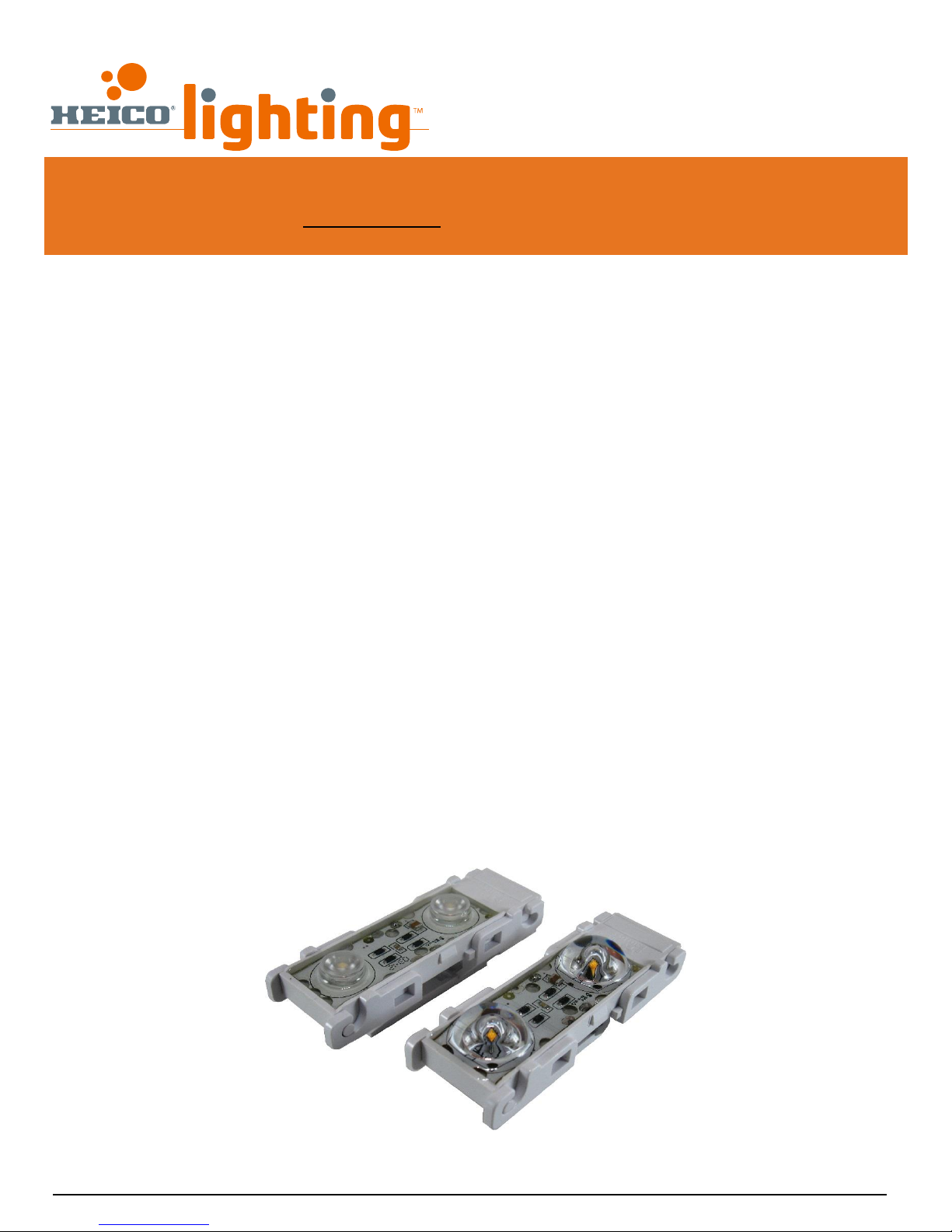
Polyoptik
TM
400, du Parc, Saint-Eustache, Québec Canada, J7R 0A1
Tel: +1.450.491.5671 +1.800.665.1166
Fax: +1.450.491.3788 www.heicolighting.com
Technical Bulletin #34
Polyoptik
TM
Architectural Lighting Applications Installation Guide
Table of Content
Loading and Photometric Information Summary……………………………………………………………………………………………………2
Loading……………………………………………………………………………………………………………………………… 3
Refer to the wiring configuration that suits your project
Twisted Pair Extension……………………………………………………………………………………………………………………………………3
BX Extension…………………………………………………………………………………………………………………………………………………. 5
Straight Pair Extension…………………………………………………………………………………………………………………………………. 7
Single Wire Loop…………………………………………………………………………………………………………………………………………….9
Single Wire Loop with Return………………………………………………………………………………………………………………………11
Twisted Pair with Single Wire Loop………………………………………………………………………………………………………………13
Twisted Pair with Single Wire Loop With Return…………………………………………………………………………………………15
Installation……………………………………………………………………………………………………………………… 20
Installation Instructions……………………………………………………………………………………………………………………………….20
PolyoptikTM Beam Orientation………………………………………………………………………………………………………………………21
Location Definitions……………………………………………………………………………………………………………………………………. 21
Power Supply Electrical Connection in Dry or Damp Locations……………………………………………………………………22
Power Supply Electrical Connection in Wet Locations…………………………………………………………………………………23
On-Site Installation………………………………………………………………………………………………………………………………………24
Warnings………………………………………………………………………………………………………………………………………………………………… 25
Contact us……………………………………………………………………………………………………………………………………………………………….25
1/25
Page 2
HEICO lightingTM Contactless LED System Polyoptik
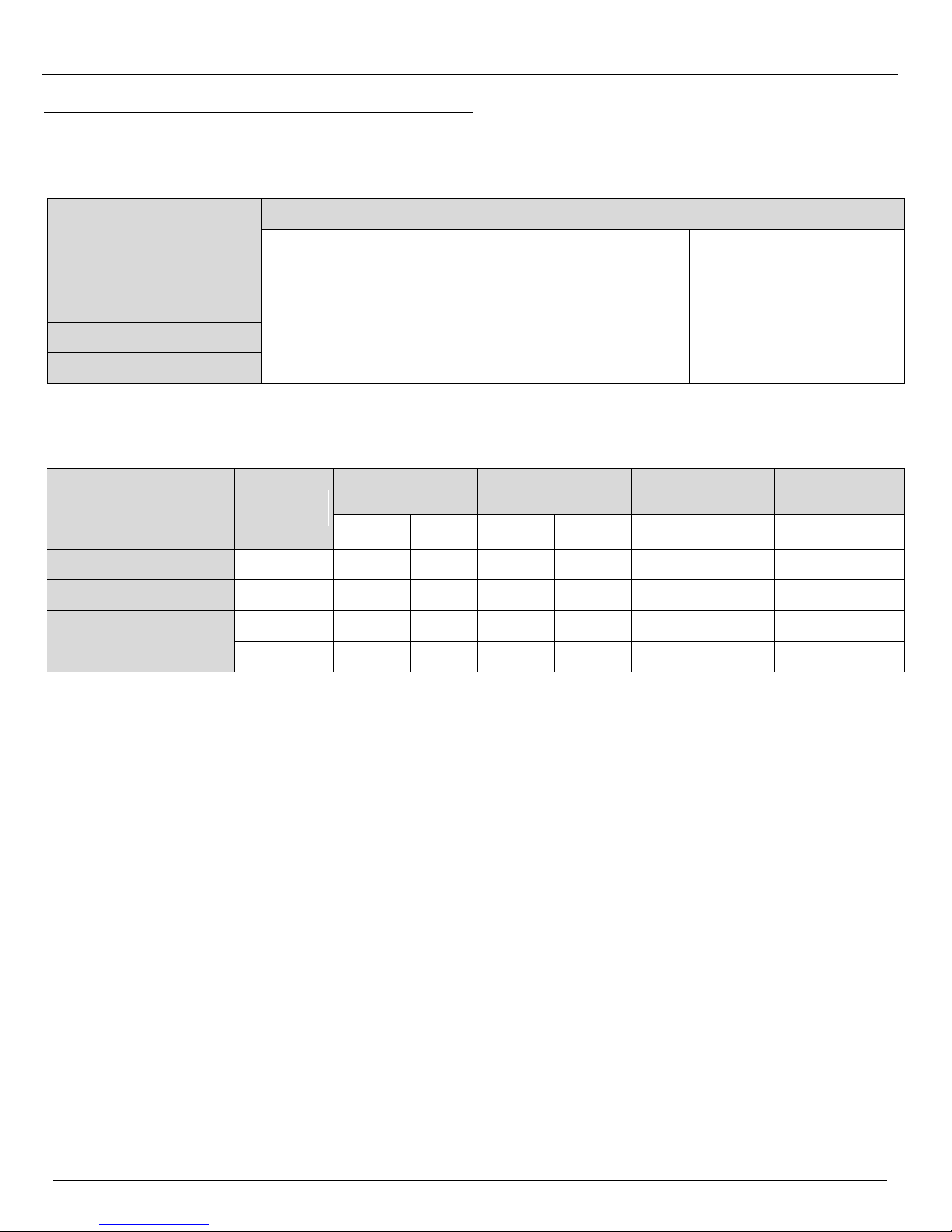
PolyoptikTM LED Modules System Loading
Model
Consumption
Maximum number of modules
Watts per module
LMPS-350/LMPS-DC350
LMPS-750
PolyoptikTM 20˚x20˚
1.35
26
55
PolyoptikTM 40˚x40˚
PolyoptikTM 20˚x40˚
PolyoptikTM 180˚x180˚
PolyoptikTM Photometric Information **
Model
Lens beam
angle
Lumens per
module
Lumens per foot*
Lumens per watt
CRI
White
3000K
White
3500K
White
3000K
White
3500K
White 3000K, 3500K
White 3000K, 3500K
PolyoptikTM 20˚x20˚
20
104
113
416
452
84
82
PolyoptikTM 40˚x40˚
40
98
103
392
412
79
82
PolyoptikTM 20˚x40˚
20 x 40
114
124
456
496
92
82
PolyoptikTM 180˚x180˚
180
98
106
392
424
79
82
* All values are for the maximum allowable number of modules per foot
** Photometric data is subject to change, LM-79 data and IES files are available for 3500K modules.
LOADING AND PHOTOMETRIC INFORMATION SUMMARY
TM
Architectural Lighting Applications Installation Guide
Specifications are subject to change without notice. (Technical bulletin #34)
© HEICO lightingTM 2013 – All rights reserved. Made in Canada. 2/25
Page 3
HEICO lightingTM Contactless LED System Polyoptik
TWISTED PAIR EXTENSION
Target distance factor =
(target distance – length 1) (distance factor 2 – distance factor 1)
+ distance factor 1
(length 2 – length 1)
Example (target distance of 88 feet with LMPS-750)
Target Distance factor =
(88 – 75) (0.69 – 0.73)
+ 0.73 = 0.71
(100 – 75)
Configuration
Power supply
Feet
0
15
25
50
75
100
125
150
14 AWG
Twisted pair
extension
(figure 1)
LMPS-350
1 1 1
0.95
0.91
0.66
0.41
N/A
LMPS-DC350
1 1 0.95
0.86
0.74
0.62
0.45
N/A
LMPS-750
1
0.85
0.81
0.77
0.73
0.69
0.57
0.50
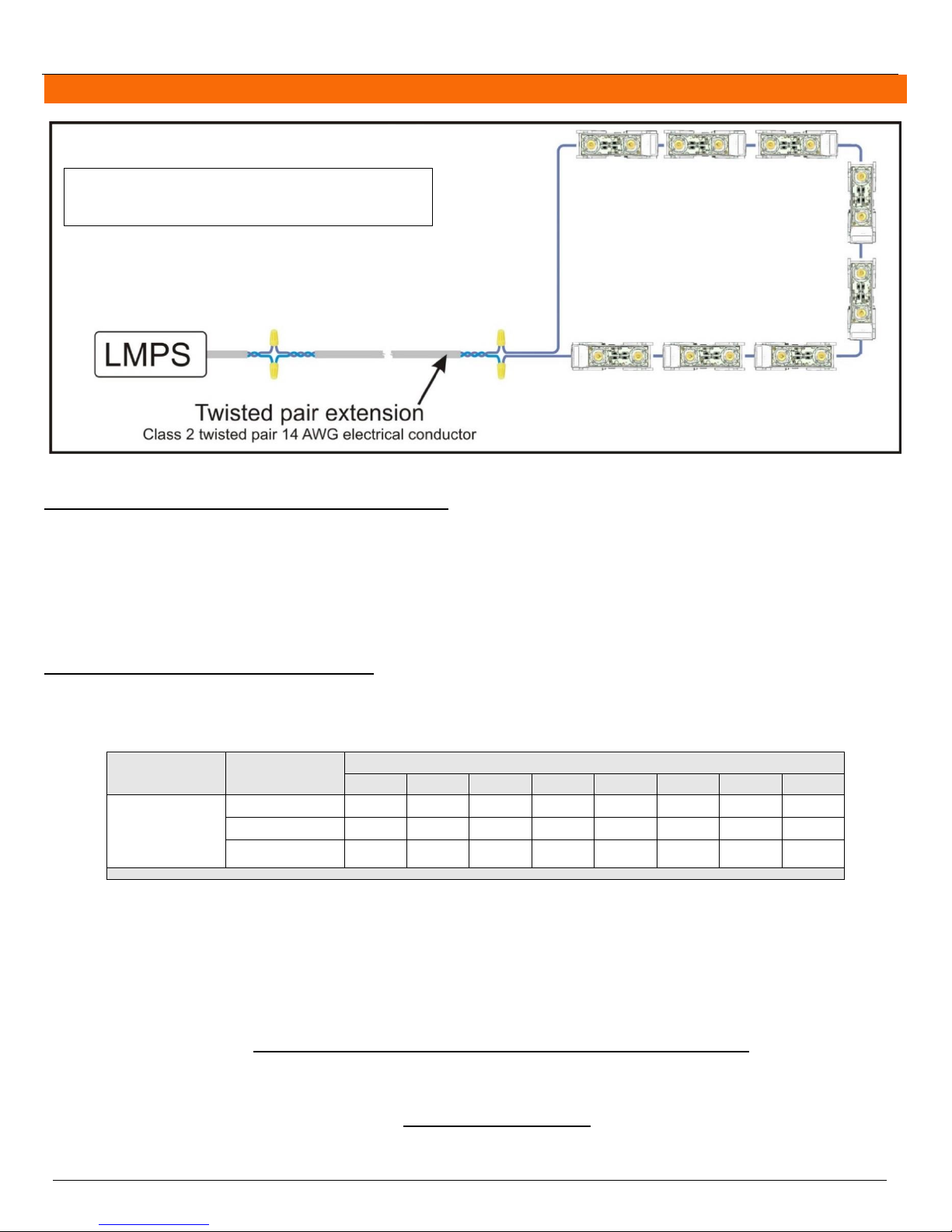
Figure 1 : Twisted pair extension
Modules are at the end of an extension.
The electrical conductor is a twisted pair type (example CL3P)
This configuration has the best transport performance signal.
TM
Architectural Lighting Applications Installation Guide
Calculating the wattage of the LEDs to be installed
The following method can also be used to calculate the load on only one power supply or individual sections of the
architectural lighting project. Please note that the “watts per module" value must be taken from the specification sheet of
the appropriate product.
wattage = number of modules X watts per module
total wattage = wattage of module type 1 + wattage of module type 2 + (…)
Applying the distance factor if applicable
If the power supply is installed away from the LEDs, use table 1 below to apply the appropriate distance factor to the
wattage of the power supply.
Table 1: Distance Factor for Twisted Pair Extension
The distance refers to the distance between the power supply and the first LED module.
Watts available for LEDs = wattage of the power supply X distance factor
The values given in table 1 are usually enough to do proper distance factor calculations. If the distance between the power
supply and the first LED module falls between two columns in table 1, it is possible to calculate the distance factor using
linear interpolation.
Specifications are subject to change without notice. (Technical bulletin #34)
© HEICO lightingTM 2013 – All rights reserved. Made in Canada. 3/25
Page 4

HEICO lightingTM Contactless LED System Polyoptik
Price of electricity per year =
Total system wattage X hours of usage per day X 365 days per year X price of electricity per kW/h
1000
EXAMPLE
Modules : 95 PolyoptikTM 20˚X20˚ 3000K & 20 PolyoptikTM 180˚X180˚ 3500K
Power supply : LMPS-750 (75W)
Twisted pair extension : 50 ft
Distance factor at 50 ft: 0.77
Wattage 1 =
95 PolyoptikTM 20˚X20˚ 3000K X 1.35 watts
= 128.25 watts
Wattage 2 =
20 PolyoptikTM 180˚X180˚ 3500K X 1.35 watts
= 27 watts
Total wattage =
128.25 watts + 27 watts
= 155.25 watts
Watts available for LEDs = 75 watts X 0.77 = 57.75 watts/power supply
Number of power supplies required = 155.25 watts total/57.75 watts/power supply = 3 LMPS-750
Therefore, to distribute the load equally, install 38 modules on each of the first 2 power supplies and install
39 modules on the third power supply for the total 115 modules.
Total system power consumption = 63 watts + 63 watts + 65 watts = 191 watts
TM
Architectural Lighting Applications Installation Guide
Calculating the number of power supplies your project requires
When using a distance factor use the “watts available for the LEDs” instead of the “wattage of the power supply”. Round
the result up to the next integer.
Number of power supplies = total wattage / wattage of the power supply
Please note that HEICO lightingTM’s LMPS-350 and LMPS-DC350 have a wattage of 35 watts and the LMPS-750 has a wattage of 75 watts.
Calculating the system wattage
Take the number of watts of LEDs at the output of each power supply and use the appropriate power curve on figure 8 (p.17)
to determine each power supply’s consumption. The average output power can also be used if the load is distributed evenly
throughout the power supplies.
Calculating the total system power consumption
The total system power consumption equals the sum of the power consumption of each power supply.
Calculating the cost of electricity for a year for the complete architectural lighting system
Please note that “Price of electricity per kW/h” is according to your local electricity rate.
Determining the system efficiency
Due to the high frequency nature of the output of the LMPS power supplies, the input power factor must be used to determine
the system efficiency. Take the input watts of each power supply and use the appropriate power factor curve on figure 9
(p.18) to determine the system efficiency.
Additional Considerations
Distribute the load equally between multiple power supplies. This ensures a uniform level of light across the power
supplies.
Contact HEICO lighting
All calculations are theoretical. Measurements made on the real life installations can differ from the calculations.
TM
for more details about power consumption calculations when using a distance factor.
Specifications are subject to change without notice. (Technical bulletin #34)
© HEICO lightingTM 2013 – All rights reserved. Made in Canada. 4/25
Page 5
HEICO lightingTM Contactless LED System Polyoptik
BX EXTENSION
Target distance factor =
(target distance – length 1) (distance factor 2 – distance factor 1)
+ distance factor 1
(length 2 – length 1)
Example (target distance of 88 feet with LMPS-750)
Target Distance factor =
(88 – 75) (0.63 – 0.69)
+ 0.69 = 0.66
(100 – 75)
Configuration
Power supply
Feet
0
15
25
50
75
100
125
150
14 AWG BX
(figure 2)
LMPS-350
1 1 .95
.86
.62
.45
N/A
N/A
LMPS-DC350
1 1 .95
.82
.66
.49
.24
N/A
LMPS-750
1
.84
.79
.73
.69
.63
.52
.36
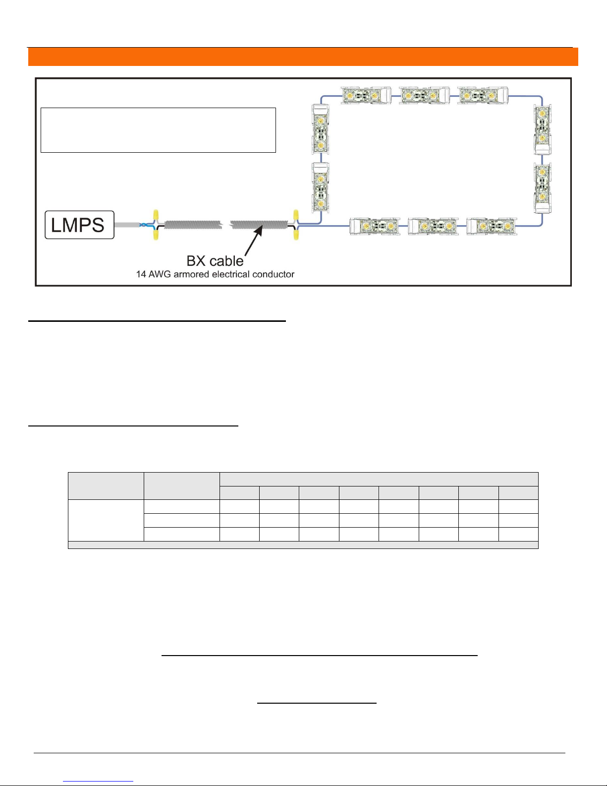
Figure 2 : BX extension
Modules are at the end of an extension.
This configuration is very practical as it enables use of easily
available armoured BX wire. It can also be used on retrofit
installations where BX wire is already installed.
TM
Architectural Lighting Applications Installation Guide
Calculating the wattage of the LEDs to be installed
The following method can also be used to calculate the load on only one power supply or individual sections of the
architectural lighting project. Please note that the “watts per module" value must be taken from the specification sheet of
the appropriate product.
wattage = number of modules X watts per module
total wattage = wattage of module type 1 + wattage of module type 2 + (…)
Applying the distance factor if applicable
If the power supply is installed away from the LEDs, use table 2 below to apply the appropriate distance factor to the
wattage of the power supply.
Table 2: Distance Factor for BX Extension
The distance refers to the distance between the power supply and the first LED module.
Watts available for LEDs = wattage of the power supply X distance factor
The values given in table 2 are usually enough to do proper distance factor calculations. If the distance between the power
supply and the first LED module falls between two columns in table 2, it is possible to calculate the distance factor using
linear interpolation.
Specifications are subject to change without notice. (Technical bulletin #34)
© HEICO lightingTM 2013 – All rights reserved. Made in Canada. 5/25
Page 6

HEICO lightingTM Contactless LED System Polyoptik
Price of electricity per year =
Total system wattage X hours of usage per day X 365 days per year X price of electricity per kW/h
1000
EXAMPLE
Modules : 95 PolyoptikTM 20˚X20˚ 3000K & 20 PolyoptikTM 180˚X180˚ 3500K
Power supply : LMPS-750 (75W)
BX extension : 50 ft
Distance factor at 50 ft: 0.73
Wattage 1 =
95 PolyoptikTM 20˚X20˚ 3000K X 1.35 watts
= 128.25 watts
Wattage 2 =
20 PolyoptikTM 180˚X180˚ 3500K X 1.35 watts
= 27 watts
Total wattage =
128.25 watts + 27 watts
= 155.25 watts
Watts available for LEDs = 75 watts X 0.73 = 54.75 watts/power supply
Number of power supplies required = 155.25 watts total/54.75 watts/power supply = 3 LMPS-750
Therefore, to distribute the load equally, install 38 modules on each of the first 2 power supplies and install
39 modules on the third power supply for the total 115 modules.
Total system power consumption = 63 watts + 63 watts + 65 watts = 191 watts
TM
Architectural Lighting Applications Installation Guide
Calculating the number of power supplies your project requires
When using a distance factor use the “watts available for the LEDs” instead of the “wattage of the power supply”. Round
the result up to the next integer.
Number of power supplies = total wattage / wattage of the power supply
Please note that HEICO lightingTM’s LMPS-350 and LMPS-DC350 have a wattage of 35 watts and the LMPS-750 has a wattage of 75 watts.
Calculating the system wattage
Take the number of watts of LEDs at the output of each power supply and use the appropriate power curve on figure 8 (p.17)
to determine each power supply’s consumption. The average output power can also be used if the load is distributed evenly
throughout the power supplies.
Calculating the total system power consumption
The total system power consumption equals the sum of the power consumption of each power supply.
Calculating the cost of electricity for a year for the complete architectural lighting project
Please note that “Price of electricity per kW/h” is according to your local electricity rate.
Determining the system efficiency
Due to the high frequency nature of the output of the LMPS power supplies, the input power factor must be used to determine
the system efficiency. Take the input watts of each power supply and use the appropriate power factor curve on figure 9
(p.18) to determine the system efficiency.
Additional Considerations
Distribute the load equally between multiple power supplies. This ensures a uniform level of light across the power
supplies.
Contact HEICO lighting
All calculations are theoretical. Measurements made on the real life installations can differ from the calculations.
TM
for more details about power consumption calculations when using a distance factor.
Specifications are subject to change without notice. (Technical bulletin #34)
© HEICO lightingTM 2013 – All rights reserved. Made in Canada. 6/25
Page 7
HEICO lightingTM Contactless LED System Polyoptik
STRAIGHT PAIR EXTENSION
Configuration
Power supply
Feet
0
15
25
50
75
100
125
150
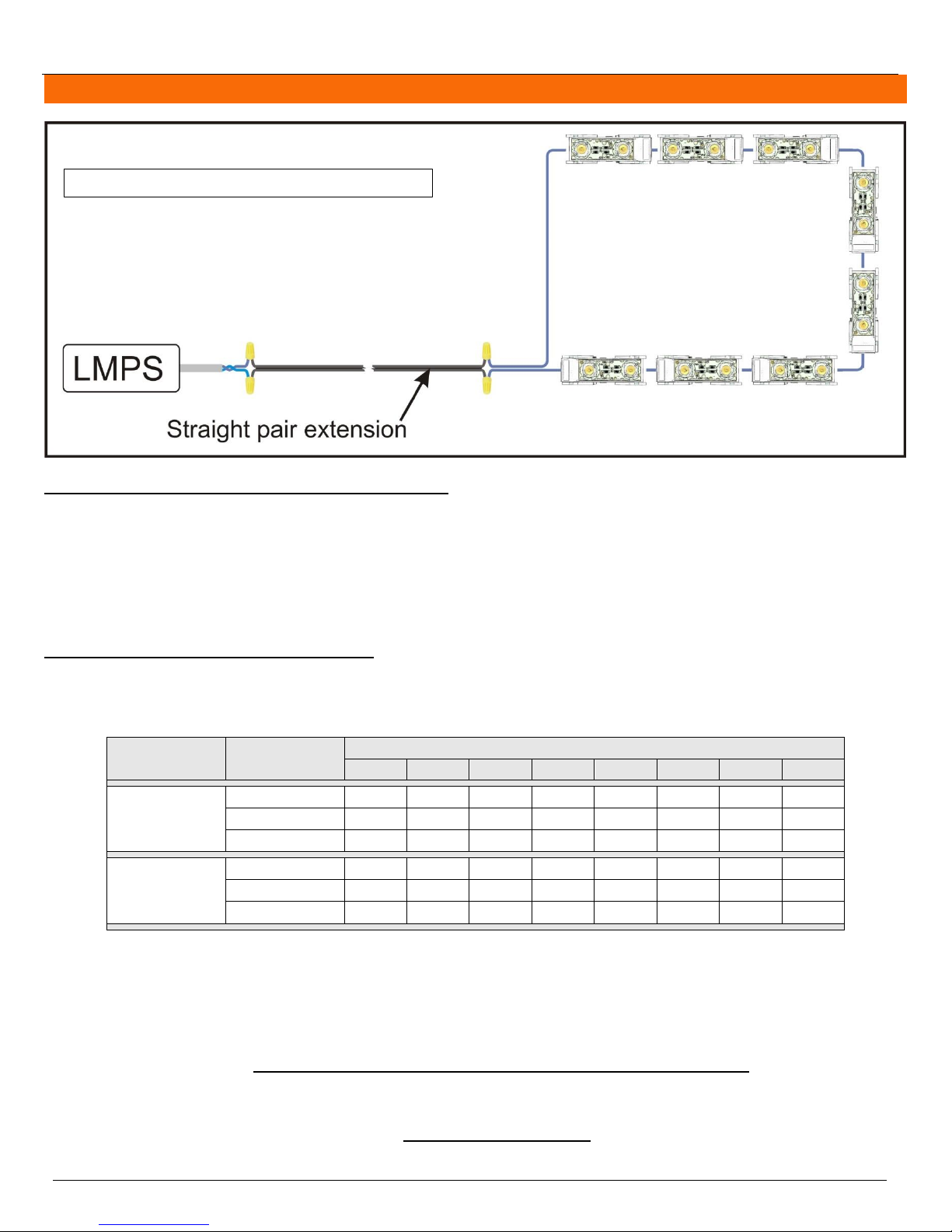
14 AWG straight
pair extension
(figure 3)
LMPS-350
1 1 1
.95
.74
.41
N/A
N/A
LMPS-DC350
1 1 .95
.82
.57
.33
N/A
N/A
LMPS-750
1
.77
.73
.69
.61
.54
.34
N/A
16 AWG &
18 AWG straight
pair extension
(figure 3)
LMPS-350
1 1 .95
.74
.41
.20
N/A
N/A
LMPS-DC350
1 1 .95
.74
.49
.24
N/A
N/A
LMPS-750
1
.73
.69
.61
.54
.42
.23
N/A
Target distance factor =
(target distance – length 1) (distance factor 2 – distance factor 1)
+ distance factor 1
(length 2 – length 1)
Example (target distance of 88 feet with LMPS-750, 14 AWG)
Target Distance factor =
(88 – 75) (0.54 – 0.61)
+ 0.69 = 0.65
(100 – 75)
Figure 3 : Straight pair extension
Modules are at the end of an extension.
TM
Architectural Lighting Applications Installation Guide
Calculating the wattage of the LEDs to be installed
The following method can also be used to calculate the load on only one power supply or individual sections of the
architectural lighting project. Please note that the “watts per module" value must be taken from the specification sheet of
the appropriate product.
wattage = number of modules X watts per module
total wattage = wattage of module type 1 + wattage of module type 2 + (…)
Applying the distance factor if applicable
If the power supply is installed away from the LEDs, use table 3 below to apply the appropriate distance factor to the
wattage of the power supply.
Table 3: Distance Factor for Straight Pair Extension
Watts available for LEDs = wattage of the power supply X distance factor
The values given in table 3 are usually enough to do proper distance factor calculations. If the distance between the power
supply and the first LED module falls between two columns in table 3, it is possible to calculate the distance factor using
linear interpolation.
The distance refers to the distance between the power supply and the first LED module.
Specifications are subject to change without notice. (Technical bulletin #34)
© HEICO lightingTM 2013 – All rights reserved. Made in Canada. 7/25
Page 8

HEICO lightingTM Contactless LED System Polyoptik
Price of electricity per year =
Total system wattage X hours of usage per day X 365 days per year X price of electricity per kW/h
1000
EXAMPLE
Modules : 95 PolyoptikTM 20˚X20˚ 3000K & 20 PolyoptikTM 180˚X180˚ 3500K
Power supply : LMPS-750 (75W)
Twisted pair extension : 50 ft
Distance factor at 50 ft: 0.69
Wattage 1 =
95 PolyoptikTM 20˚X20˚ 3000K X 1.35 watts
= 128.25 watts
Wattage 2 =
20 PolyoptikTM 180˚X180˚ 3500K X 1.35 watts
= 27 watts
Total wattage =
128.25 watts + 27 watts
= 155.25 watts
Watts available for LEDs = 75 watts X 0.69 = 51.75 watts/power supply
Number of power supplies required = 155.25 watts total/51.75 watts/power supply = 3 LMPS-750
Therefore, to distribute the load equally, install 38 modules on each power supply for the total 115 modules.
Total system power consumption = 63 watts + 63 watts + 63 watts = 189 watts
TM
Architectural Lighting Applications Installation Guide
Calculating the number of power supplies your project requires
When using a distance factor use the “watts available for the LEDs” instead of the “wattage of the power supply”. Round
the result up to the next integer.
Number of power supplies = total wattage / wattage of the power supply
Please note that HEICO lightingTM’s LMPS-350 and LMPS-DC350 have a wattage of 35 watts and the LMPS-750 has a wattage of 75 watts.
Calculating the system wattage
Take the number of watts of LEDs at the output of each power supply and use the appropriate power curve on figure 8 (p.17)
to determine each power supply’s consumption. The average output power can also be used if the load is distributed evenly
throughout the power supplies.
Calculating the total system power consumption
The total system power consumption equals the sum of the power consumption of each power supply.
Calculating the cost of electricity for a year for the complete architectural lighting project
Please note that “Price of electricity per kW/h” is according to your local electricity rate.
Determining the system efficiency
Due to the high frequency nature of the output of the LMPS power supplies, the input power factor must be used to determine
the system efficiency. Take the input watts of each power supply and use the appropriate power factor curve on figure 9
(p.18) to determine the system efficiency.
Additional Considerations
Distribute the load equally between multiple power supplies. This ensures a uniform level of light across the power
supplies.
Contact HEICO lighting
All calculations are theoretical. Measurements made on the real life installations can differ from the calculations.
TM
for more details about power consumption calculations when using a distance factor.
Specifications are subject to change without notice. (Technical bulletin #34)
© HEICO lightingTM 2013 – All rights reserved. Made in Canada. 8/25
Page 9
HEICO lightingTM Contactless LED System Polyoptik
SINGLE WIRE LOOP
Configuration
Power supply
Feet
0
15
25
50
75
100
125
150
14 AWG single
wire loop
(figure 4)
LMPS-350
1 1 1
.87
.61
.34
N/A
N/A
LMPS-DC350
1 1 1
.78
.61
.26
N/A
N/A
LMPS-750
1 1 1 1 .65
.32
.20
N/A
16 & 18 AWG
single wire
loop
(figure 4)
LMPS-350
1 1 .95
.74
.24
N/A
N/A
N/A
LMPS-DC350
1 1 .95
.74
.24
N/A
N/A
N/A
LMPS-750
1
.77
.73
.69
.54
.27
N/A
N/A
Target distance factor =
(target distance – length 1) (distance factor 2 – distance factor 1)
+ distance factor 1
(length 2 – length 1)
Example (target distance of 88 feet with LMPS-750, 14 AWG)
Target distance factor =
(88 – 75) (0.32 – 0.65)
+ 0.65 = 0.48
(100 – 75)
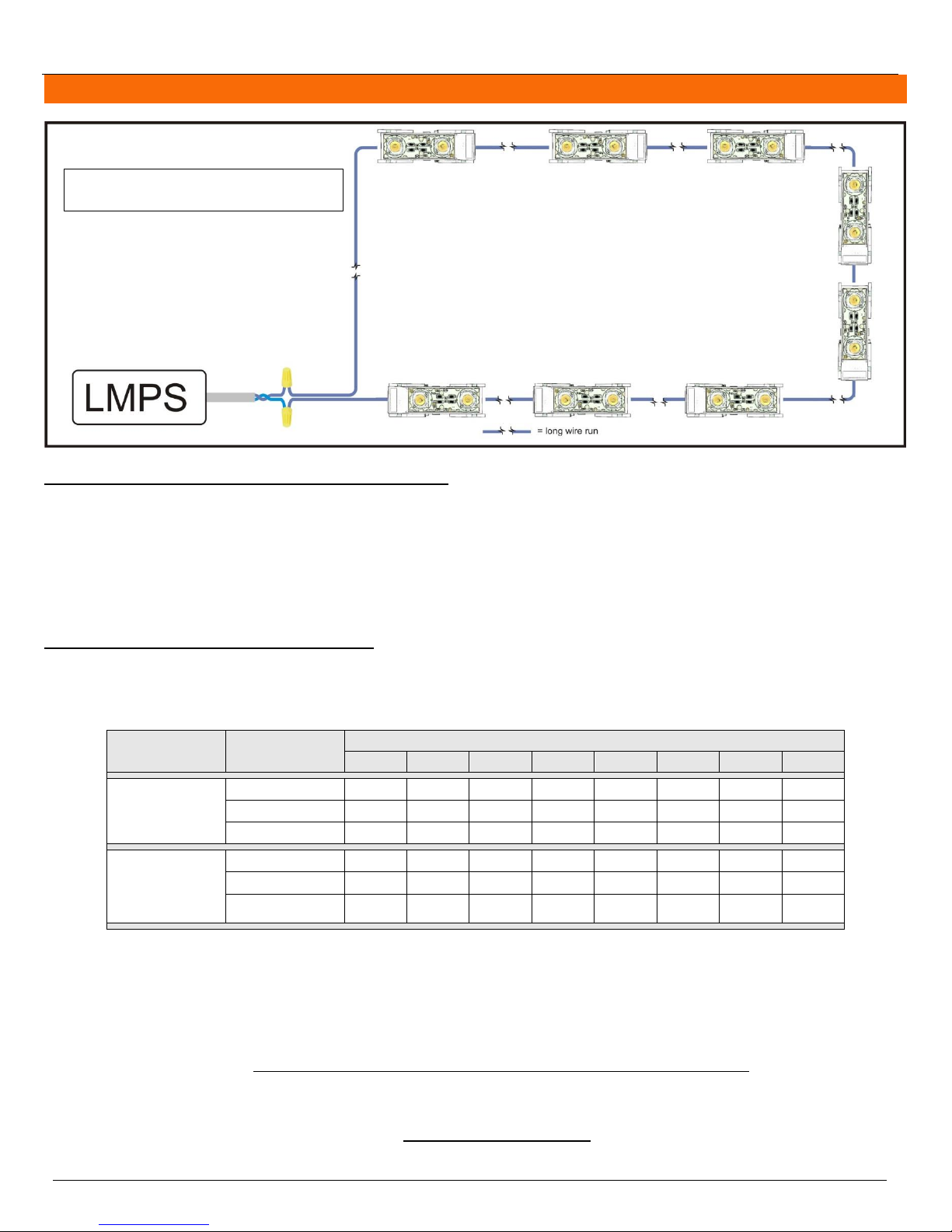
Figure 4 : Single wire loop
Modules are distributed on a long single
wire.
TM
Architectural Lighting Applications Installation Guide
Calculating the wattage of the LEDs to be installed
The following method can also be used to calculate the load on only one power supply or individual sections of the
architectural lighting project. Please note that the “watts per module" value must be taken from the specification sheet of
the appropriate product.
wattage = number of modules X watts per module
total wattage = wattage of module type 1 + wattage of module type 2 + (…)
Applying the distance factor if applicable
If the power supply is installed away from the LEDs, use table 4 below to apply the appropriate distance factor to the
wattage of the power supply.
Table 4: Distance Factor for Single Wire Loop
The distance refers to the distance between the power supply and the first LED module.
Watts available for LEDs = wattage of the power supply X distance factor
The values given in table 4 are usually enough to do proper distance factor calculations. If the distance between the
power supply and the first LED module falls between two columns in table 4, it is possible to calculate the distance factor
using linear interpolation.
Specifications are subject to change without notice. (Technical bulletin #34)
© HEICO lightingTM 2013 – All rights reserved. Made in Canada. 9/25
Page 10

HEICO lightingTM Contactless LED System Polyoptik
Price of electricity per year =
Total system wattage X hours of usage per day X 365 days per year X price of electricity per kW/h
1000
EXAMPLE
Modules : 95 PolyoptikTM 20˚X20˚ 3000K & 20 PolyoptikTM 180˚X180˚ 3500K
Power supply : LMPS-750 (75W)
Twisted pair extension : 50 ft
Distance factor at 50 ft: 1
Wattage 1 =
95 PolyoptikTM 20˚X20˚ 3000K X 1.35 watts
= 128.25 watts
Wattage 2 =
20 PolyoptikTM 180˚X180˚ 3500K X 1.35 watts
= 27 watts
Total wattage =
128.25 watts + 27 watts
= 155.25 watts
Watts available for LEDs = 75 watts X 1 = 75 watts/power supply
Number of power supplies required = 155.25 watts total/75 watts/power supply = 3 LMPS-750
Therefore, to distribute the load equally, install 38 modules on each of the first 2 power supplies and install
39 modules on the third power supply for the total 115 modules.
Total system power consumption = 63 watts + 63 watts + 65 watts = 191 watts
TM
Architectural Lighting Applications Installation Guide
Calculating the number of power supplies your project requires
When using a distance factor use the “watts available for the LEDs” instead of the “wattage of the power supply”. Round
the result up to the next integer.
Number of power supplies = total wattage / wattage of the power supply
Please note that HEICO lightingTM’s LMPS-350 and LMPS-DC350 have a wattage of 35 watts and the LMPS-750 has a wattage of 75 watts.
Calculating the system wattage
Take the number of watts of LEDs at the output of each power supply and use the appropriate power curve on figure 8 (p.17)
to determine each power supply’s consumption. The average output power can also be used if the load is distributed evenly
throughout the power supplies.
Calculating the total system power consumption
The total system power consumption equals the sum of the power consumption of each power supply.
Calculating the cost of electricity for a year for the complete architectural lighting project
Please note that “Price of electricity per kW/h” is according to your local electricity rate.
Determining the system efficiency
Due to the high frequency nature of the output of the LMPS power supplies, the input power factor must be used to determine
the system efficiency. Take the input watts of each power supply and use the appropriate power factor curve on figure 9
(p.18) to determine the system efficiency.
Additional Considerations
Distribute the load equally between multiple power supplies. This ensures a uniform level of light across the power
supplies.
Contact HEICO lighting
All calculations are theoretical. Measurements made on the real life installation can differ from the calculations.
TM
for more details about power consumption calculations when using a distance factor.
Specifications are subject to change without notice. (Technical bulletin #34)
© HEICO lightingTM 2013 – All rights reserved. Made in Canada. 10/25
Page 11
HEICO lightingTM Contactless LED System Polyoptik
SINGLE WIRE LOOP WITH RETURN
Configuration
Power supply
Feet
0
15
25
50
75
100
125
150
14 AWG single
wire loop with
return
(figure 5)
LMPS-350
1 1 1 1 1
.95
.95
.66
LMPS-DC350
1 1 1
.96
.74
.49
N/A
N/A
LMPS-750
1 1 1
.77
.73
.65
.54
.34
Target distance factor =
(target distance – length 1) (distance factor 2 – distance factor 1)
+ distance factor 1
(length 2 – length 1)
Example (target distance = 88 feet)
Target Distance factor =
(88 – 75) (0.65 – 0.73)
+ 0.73 = 0.69
(100 – 75)
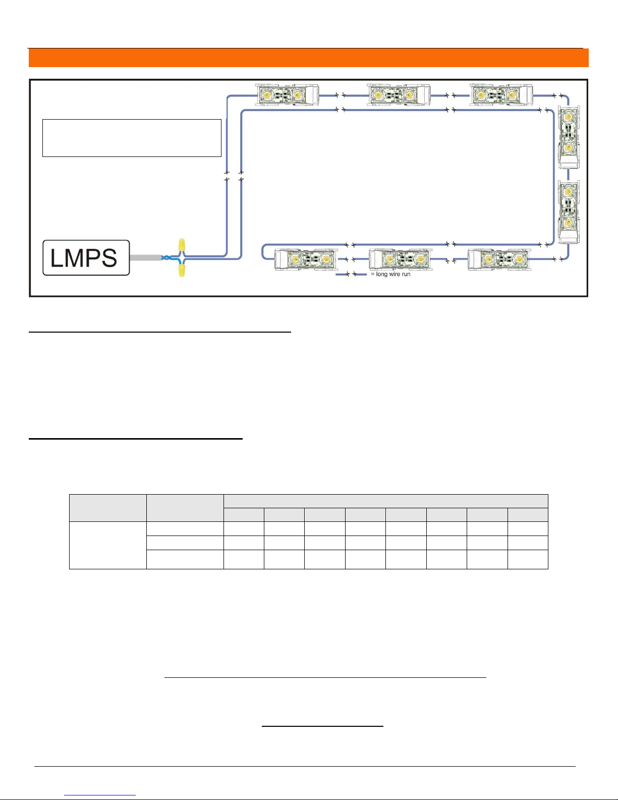
Figure 5 :
Single wire loop with return
Modules are distributed on a long single
wire and the wire comes back along the
modules.
TM
Architectural Lighting Applications Installation Guide
Calculating the wattage of the LEDs to be installed
The following method can also be used to calculate the load on only one power supply or individual sections of the
architectural lighting project. Please note that the “watts per module" value must be taken from the specification sheet of
the appropriate product.
wattage = number of modules X watts per module
total wattage = wattage of module type 1 + wattage of module type 2 + (…)
Applying the distance factor if applicable
If the power supply is installed away from the LEDs, use table 5 below to apply the appropriate distance factor to the
wattage of the power supply.
Table 5: Distance Factor for Single Wire Loop With Return
The distance refers to the distance between the power supply and the first LED module.
Watts available for LEDs = wattage of the power supply X distance factor
The values given in table 5 are usually enough to do proper distance factor calculations. If the distance between the
power supply and the first LED module falls between two columns in table 5, it is possible to calculate the distance factor
using linear interpolation.
Specifications are subject to change without notice. (Technical bulletin #34)
© HEICO lightingTM 2013 – All rights reserved. Made in Canada. 11/25
Page 12

HEICO lightingTM Contactless LED System Polyoptik
Price of electricity per year =
Total system wattage X hours of usage per day X 365 days per year X price of electricity per kW/h
1000
EXAMPLE
Modules : 95 PolyoptikTM 20˚X20˚ 3000K & 20 PolyoptikTM 180˚X180˚ 3500K
Power supply : LMPS-750 (75W)
Twisted pair extension : 50 ft
Distance factor at 50 ft: 0.77
Wattage 1 =
95 PolyoptikTM 20˚X20˚ 3000K X 1.35 watts
= 128.25 watts
Wattage 2 =
20 PolyoptikTM 180˚X180˚ 3500K X 1.35 watts
= 27 watts
Total wattage =
128.25 watts + 27 watts
= 155.25 watts
Watts available for LEDs = 75 watts X 0.77 = 57.75 watts/power supply
Number of power supplies required = 155.25 watts total/57.75 watts/power supply = 3 LMPS-750
Therefore, to distribute the load equally, install 38 modules on each of the first 2 power supplies and install
39 modules on the third power supply for the total 115 modules.
Total system power consumption = 63 watts + 63 watts + 65 watts = 191 watts
TM
Architectural Lighting Applications Installation Guide
Calculating the number of power supplies your project requires
When using a distance factor use the “watts available for the LEDs” instead of the “wattage of the power supply”. Round
the result up to the next integer.
Number of power supplies = total wattage / wattage of the power supply
Please note that HEICO lightingTM’s LMPS-350 and LMPS-DC350 have a wattage of 35 watts and the LMPS-750 has a wattage of 75 watts.
Calculating the system wattage
Take the number of watts of LEDs at the output of each power supply and use the appropriate power curve on figure 8 (p.17)
to determine each power supply’s consumption. The average output power can also be used if the load is distributed evenly
throughout the power supplies.
Calculating the total system power consumption
The total system power consumption equals the sum of the power consumption of each power supply.
Calculating the cost of electricity for a year for the complete architectural lighting project
Please note that “Price of electricity per kW/h” is according to your local electricity rate.
Determining the system efficiency
Due to the high frequency nature of the output of the LMPS power supplies, the input power factor must be used to determine
the system efficiency. Take the input watts of each power supply and use the appropriate power factor curve on figure 9
(p.18) to determine the system efficiency.
Additional Considerations
Distribute the load equally between multiple power supplies. This ensures a uniform level of light across the power
supplies.
Contact HEICO lighting
All calculations are theoretical. Measurements made on the real life installations can differ from the calculations.
TM
for more details about power consumption calculations when using a distance factor.
Specifications are subject to change without notice. (Technical bulletin #34)
© HEICO lightingTM 2013 – All rights reserved. Made in Canada. 12/25
Page 13
HEICO lightingTM Contactless LED System Polyoptik
TWISTED PAIR WITH SINGLE WIRE LOOP
Power supply
Length of
twisted pair
extension
Feet of single wire loop
15
25
50
75
LMPS-350
15
0.95
0.95
0.49
N/A
25
0.91
0.82
0.41
N/A
50
0.66
.57
N/A
N/A
75
0.41
0.33
N/A
N/A
LMPS-750
15
0.77
0.77
.65
.46
25
0.73
0.73
.61
.34
50
0.73
0.69
.50
N/A
75
0.65
0.61
.34
N/A
100
0.61
0.50
N/A
N/A
125
0.46
0.34
N/A
N/A
150
0.34
0.23
N/A
N/A
Target distance factor =
(target distance – length 1) (distance factor 2 – distance factor 1)
+ distance factor 1
(length 2 – length 1)
Example (target distance of 88 feet with LMPS-750)
Target Distance factor =
(30 – 25) (0.50 – 0.69)
+ 0.69 = 0.65
(50 – 25)
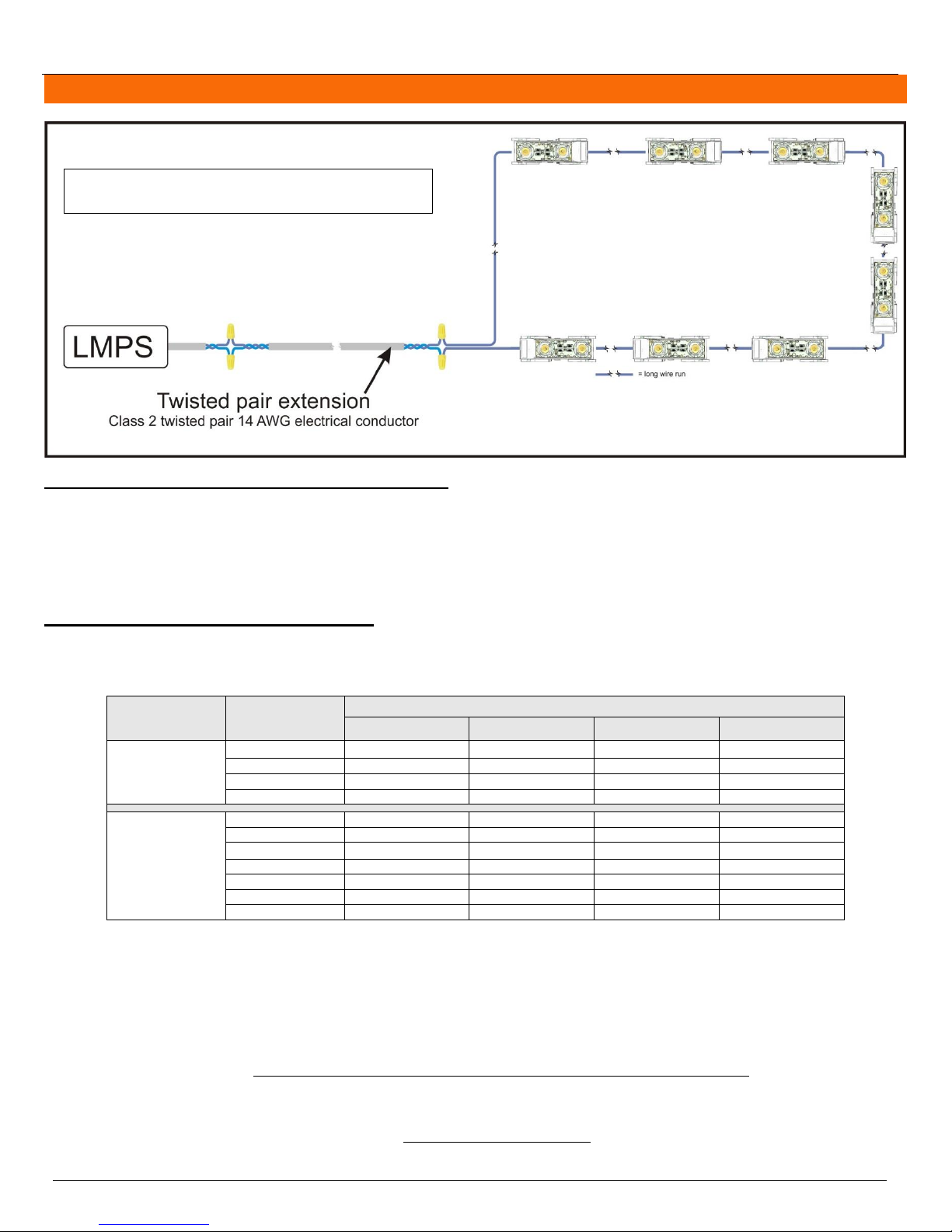
Figure 6 : Twisted pair with single wire loop
Modules are at the end of a twisted pair extension and
distributed on a long single wire.
TM
Architectural Lighting Applications Installation Guide
Calculating the wattage of the LEDs to be installed
The following method can also be used to calculate the load on only one power supply or individual sections of the
architectural lighting project. Please note that the “watts per module" value must be taken from the specification sheet of
the appropriate product.
wattage = number of modules X watts per module
total wattage = wattage of module type 1 + wattage of module type 2 + (…)
Applying the distance factor if applicable
If the power supply is installed away from the LEDs, use table 6 below to apply the appropriate distance factor to the
wattage of the power supply.
Table 6: Distance Factor for Twisted Pair With Single Wire Loop
The distance refers to the distance between the power supply and the first LED module.
Watts available for LEDs = wattage of the power supply X distance factor
The values given in table 6 are usually enough to do proper distance factor calculations. If the distance between the
power supply and the first LED module falls between two columns in table 6, it is possible to calculate the distance factor
using linear interpolation.
Specifications are subject to change without notice. (Technical bulletin #34)
© HEICO lightingTM 2013 – All rights reserved. Made in Canada. 13/25
Page 14

HEICO lightingTM Contactless LED System Polyoptik
Price of electricity per year =
Total system wattage X hours of usage per day X 365 days per year X price of electricity per kW/h
1000
EXAMPLE
Modules : 95 PolyoptikTM 20˚X20˚ 3000K & 20 PolyoptikTM 180˚X180˚ 3500K
Power supply : LMPS-750 (75W)
Twisted pair extension : 50 ft ; Single wire loop: 50 ft
Distance factor : 0.50
Wattage 1 =
95 PolyoptikTM 20˚X20˚ 3000K X 1.35 watts
= 128.25 watts
Wattage 2 =
20 PolyoptikTM 180˚X180˚ 3500K X 1.35 watts
= 27 watts
Total wattage =
128.25 watts + 27 watts
= 155.25 watts
Watts available for LEDs = 75 watts X 0.50 = 37.5 watts/power supply
Number of power supplies required = 155.25 watts total/37.5 watts/power supply = 5 LMPS-750
Therefore, to distribute the load equally, install 23 modules on each power supply for the total 115 modules.
Total system power consumption = 40 watts + 40 watts + 40 watts + 40 watts + 40 watts = 200 watts
TM
Architectural Lighting Applications Installation Guide
Calculating the number of power supplies your project requires
When using a distance factor use the “watts available for the LEDs” instead of the “wattage of the power supply”. Round
the result up to the next integer.
Number of power supplies = total wattage / wattage of the power supply
Please note that HEICO lightingTM’s LMPS-350 and LMPS-DC350 have a wattage of 35 watts and the LMPS-750 has a wattage of 75 watts.
Calculating the system wattage
Take the number of watts of LEDs at the output of each power supply and use the appropriate power curve on figure 8 (p.17)
to determine each power supply’s consumption. The average output power can also be used if the load is distributed evenly
throughout the power supplies.
Calculating the total system power consumption
The total system power consumption equals the sum of the power consumption of each power supply.
Calculating the cost of electricity for a year for the complete architectural lighting project
Please note that “Price of electricity per kW/h” is according to your local electricity rate.
Determining the system efficiency
Due to the high frequency nature of the output of the LMPS power supplies, the input power factor must be used to determine
the system efficiency. Take the input watts of each power supply and use the appropriate power factor curve on figure 9
(p.18) to determine the system efficiency.
Additional Considerations
Distribute the load equally between multiple power supplies. This ensures a uniform level of light across the power
supplies.
Contact HEICO lighting
All calculations are theoretical. Measurements made on the real life installations can differ from the calculations.
TM
for more details about power consumption calculations when using a distance factor.
Specifications are subject to change without notice. (Technical bulletin #34)
© HEICO lightingTM 2013 – All rights reserved. Made in Canada. 14/25
Page 15
HEICO lightingTM Contactless LED System Polyoptik
TWISTED PAIR WITH SINGLE WIRE LOOP WITH RETURN
Power supply
Length of
twisted pair
extension
Feet of single wire loop with return
15
25
50
75
100
125
LMPS-350
15
.95
.95
.74
.49
N/A
N/A
25
.95
.91
.66
.33
N/A
N/A
50
.82
.66
.41
N/A
N/A
N/A
75
.49
.41
N/A
N/A
N/A
N/A
LMPS-750
15
.77
.77
.69
.65
.61
.42
25
.77
.73
.69
.65
.57
.38
50
.69
.65
.65
.54
.42
N/A
75
.65
.61
.50
.42
N/A
N/A
100
.61
.57
.42
N/A
N/A
N/A
125
.50
.42
N/A
N/A
N/A
N/A
150
.38
.27
N/A
N/A
N/A
N/A
Target distance factor =
(target distance – length 1) (distance factor 2 – distance factor 1)
+ distance factor 1
(length 2 – length 1)
Example (target distance = 88 feet)
Target Distance factor =
(88 – 75) (0.42 – 0.54)
+ 0.54 = 0.48
(100 – 75)
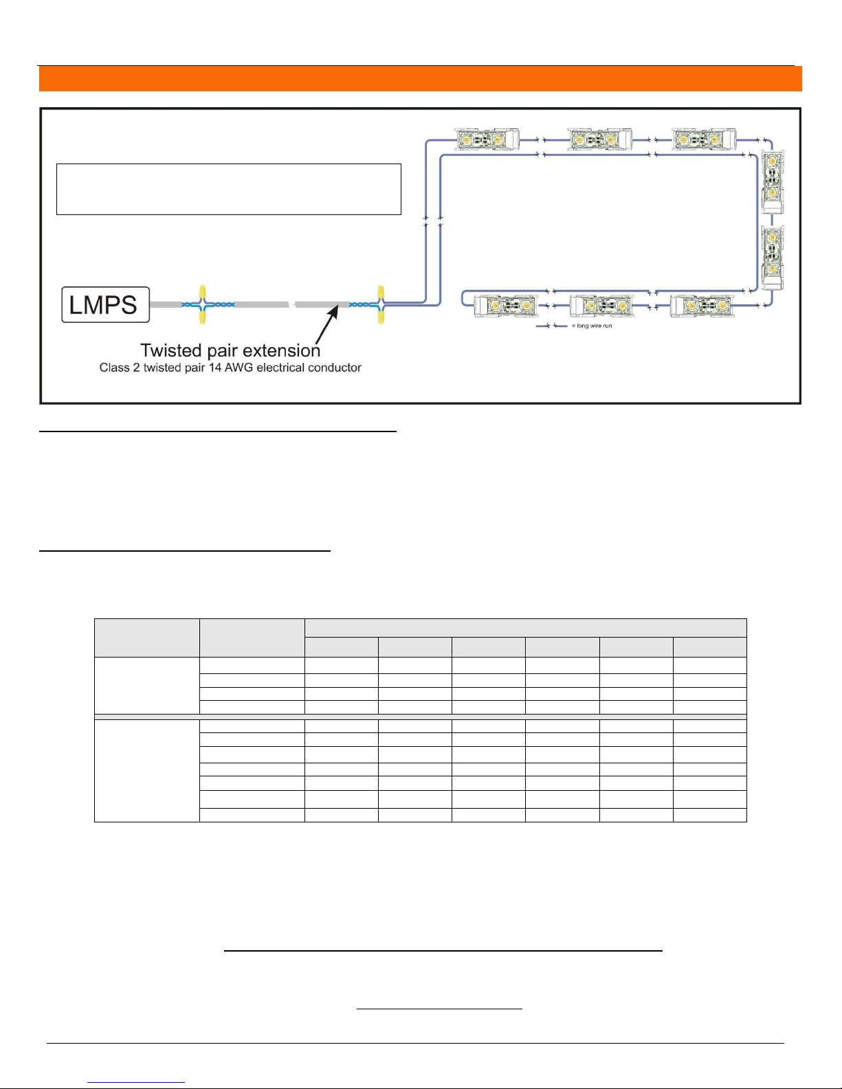
Figure 7 : Twisted pair with single wire loop
with return
Modules are at the end of a twisted pair extension and
distributed on a long single wire and the wire comes back
along the modules.
TM
Architectural Lighting Applications Installation Guide
Calculating the wattage of the LEDs to be installed
The following method can also be used to calculate the load on only one power supply or individual sections of the
architectural lighting project. Please note that the “watts per module" value must be taken from the specification sheet of
the appropriate product.
wattage = number of modules X watts per module
total wattage = wattage of module type 1 + wattage of module type 2 + (…)
Applying the distance factor if applicable
If the power supply is installed away from the LEDs, use table 7 below to apply the appropriate distance factor to the
wattage of the power supply.
Table 7: Distance Factor for Twisted Pair Extension
The distance refers to the distance between the power supply and the first module.
Watts available for LEDs = wattage of the power supply X distance factor
The values given in table 7 are usually enough to do proper distance factor calculations. If the distance between the power
supply and the first LED module falls between two columns in table 7, it is possible to calculate the distance factor using
linear interpolation.
Specifications are subject to change without notice. (Technical bulletin #34)
© HEICO lightingTM 2013 – All rights reserved. Made in Canada. 15/25
Page 16

HEICO lightingTM Contactless LED System Polyoptik
Price of electricity per year =
Total system wattage X hours of usage per day X 365 days per year X price of electricity per kW/h
1000
EXAMPLE
Modules : 95 PolyoptikTM 20˚X20˚ 3000K & 20 PolyoptikTM 180˚X180˚ 3500K
Power supply : LMPS-750 (75W)
Twisted pair extension : 50 ft
Distance factor at 50 ft: 0.65
Wattage 1 =
95 PolyoptikTM 20˚X20˚ 3000K X 1.35 watts
= 128.25 watts
Wattage 2 =
20 PolyoptikTM 180˚X180˚ 3500K X 1.35 watts
= 27 watts
Total wattage =
128.25 watts + 27 watts
= 155.25 watts
Watts available for LEDs = 75 watts X 0.65 = 48.75 watts/power supply
Number of power supplies required = 155.25 watts total/48.75 watts/power supply = 4 LMPS-750
Therefore, to distribute the load equally, install 29 modules on each of the first 3 power supplies and install
28 modules on the fourth power supply for the total 115 modules.
Total system power consumption = 50 watts + 50 watts + 50 watts + 48 watts = 198 watts
TM
Architectural Lighting Applications Installation Guide
Calculating the number of power supplies your project requires
When using a distance factor use the “watts available for the LEDs” instead of the “wattage of the power supply”. Round
the result up to the next integer.
Number of power supplies = total wattage / wattage of the power supply
Please note that HEICO lightingTM’s LMPS-350 and LMPS-DC350 have a wattage of 35 watts and the LMPS-750 has a wattage of 75 watts.
Calculating the system wattage
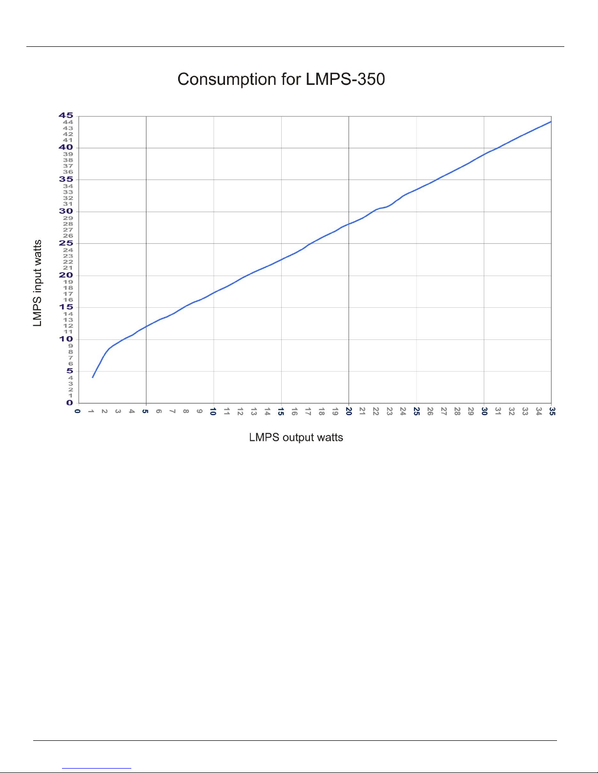
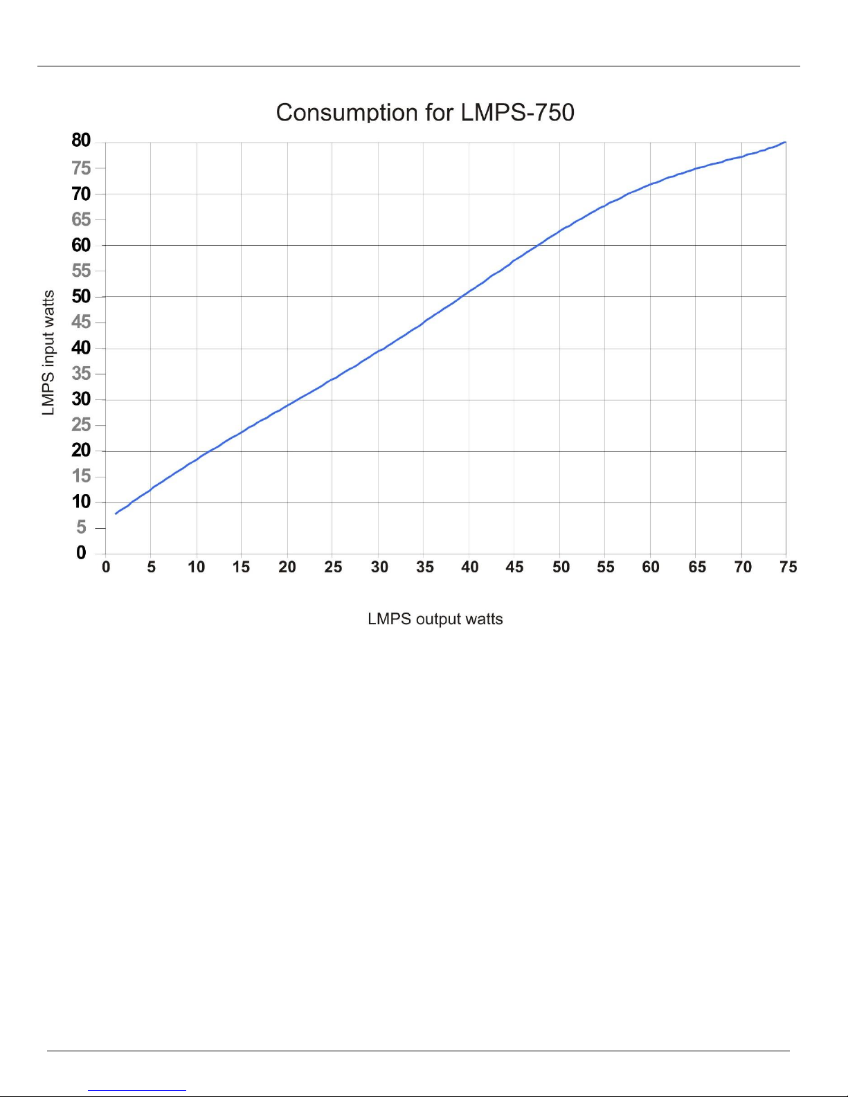
Take the number of watts of LEDs at the output of each power supply and use the appropriate power curve on figure 8 (p.17)
to determine each power supply’s consumption. The average output power can also be used if the load is distributed evenly
throughout the power supplies.
Calculating the total system power consumption
The total system power consumption equals the sum of the power consumption of each power supply.
Calculating the cost of electricity for a year for the complete architectural lighting project
Please note that “Price of electricity per kW/h” is according to your local electricity rate.
Determining the system efficiency
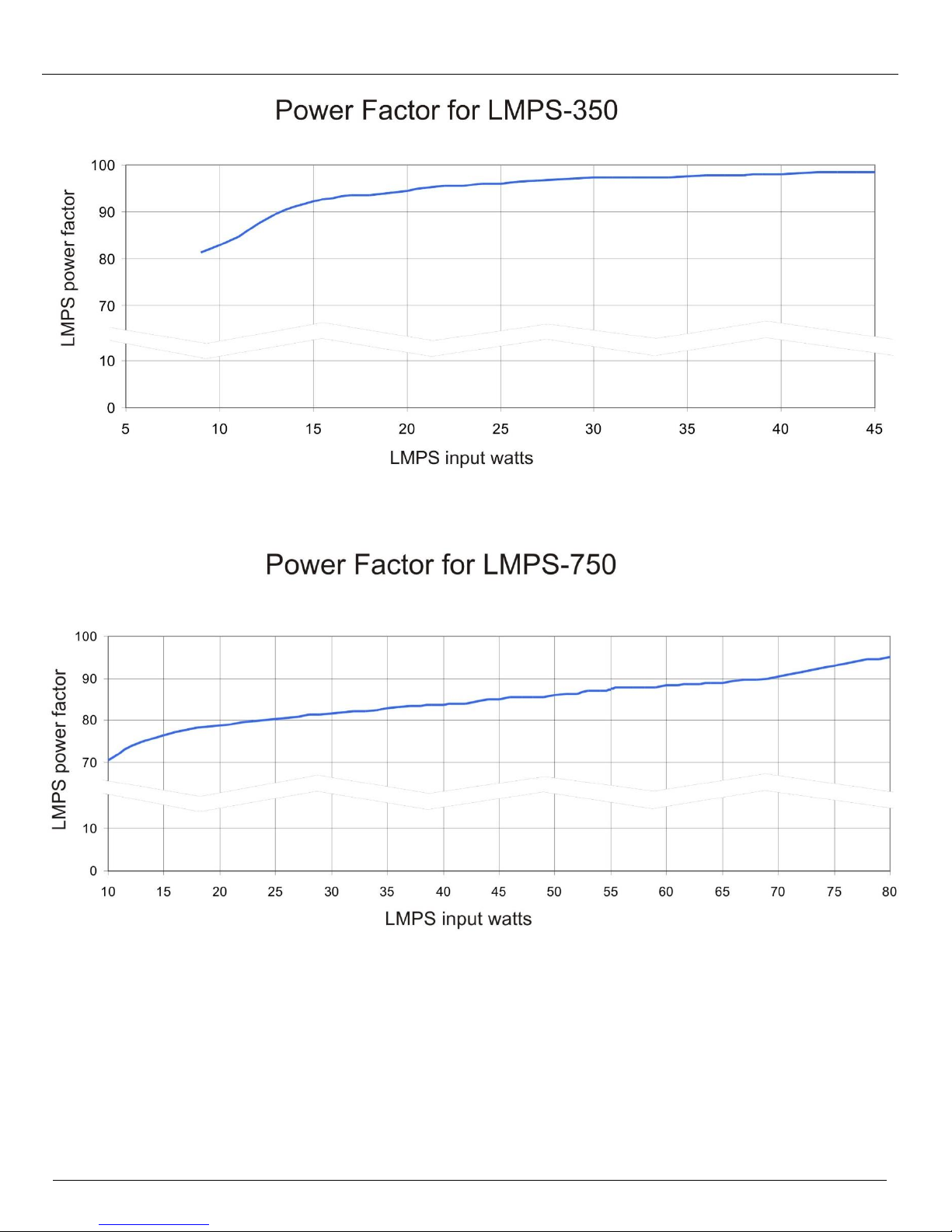
Due to the high frequency nature of the output of the LMPS power supplies, the input power factor must be used to determine
the system efficiency. Take the input watts of each power supply and use the appropriate power factor curve on figure 9
(p.18) to determine the system efficiency.
Additional Considerations
Distribute the load equally between multiple power supplies. This ensures a uniform level of light across the power
supplies.
Contact HEICO lighting
All calculations are theoretical. Measurements made on the real life installations can differ from the calculations.
TM
for more details about power consumption calculations when using a distance factor.
Specifications are subject to change without notice. (Technical bulletin #34)
© HEICO lightingTM 2013 – All rights reserved. Made in Canada. 16/25
Page 17
HEICO lightingTM Contactless LED System Polyoptik
TM
Architectural Lighting Applications Installation Guide
Figure 8.1: LMPS-350 system power consumption
Specifications are subject to change without notice. (Technical bulletin #34)
© HEICO lightingTM 2013 – All rights reserved. Made in Canada. 17/25
Page 18
HEICO lightingTM Contactless LED System Polyoptik
TM
Architectural Lighting Applications Installation Guide
Figure 8.2: LMPS-750 system power consumption
Specifications are subject to change without notice. (Technical bulletin #34)
© HEICO lightingTM 2013 – All rights reserved. Made in Canada. 18/25
Page 19
HEICO lightingTM Contactless LED System Polyoptik
TM
Architectural Lighting Applications Installation Guide
Figure 9.1: LMPS system efficiency
Specifications are subject to change without notice. (Technical bulletin #34)
© HEICO lightingTM 2013 – All rights reserved. Made in Canada. 19/25
Figure 9.2: LMPS system efficiency
Page 20
HEICO lightingTM Contactless LED System Polyoptik
TM
Architectural Lighting Applications Installation Guide
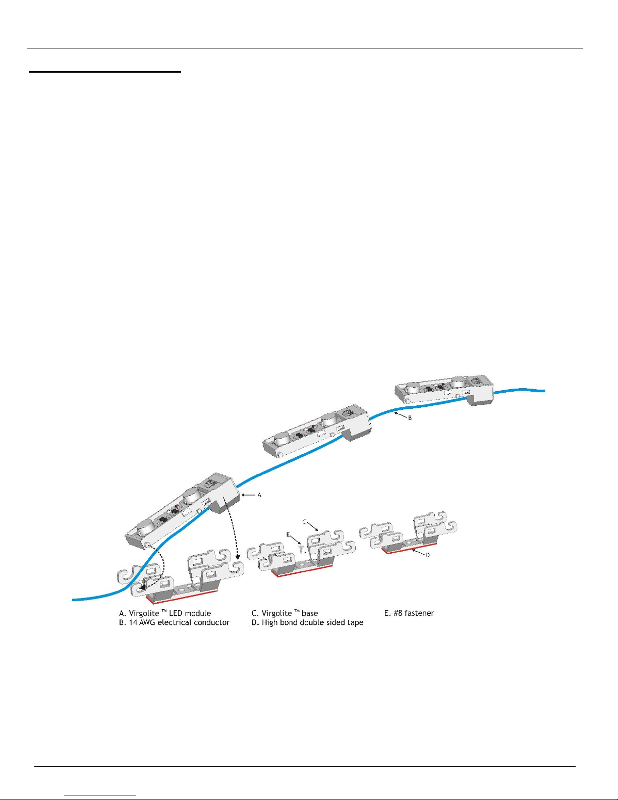
INSTALLATION INSTRUCTIONS
1. Installation shall be done in accordance with the national electrical code and any other electrical code applicable
in your area. Also follow local electrical code ordinances when applicable.
2. Clean and remove all dust and debris from the area where the modules will be installed. Keep the area clean
throughout the installation.
3. The modules installed in the same area should have the same bin letter.
4. Lay the bases by either using the provided double-sided tape or by holding them in place using #8 fasteners where
necessary.
5. Insert the 14 AWG electrical conductor (stranded wire) in the modules and snap them in the bases. All modules are
to be wired in series (figure 10).
6. If a dimmer is used, refer to the installation requirements in technical bulletin #11 “LMPS-DIMMER Architectural
Lighting Installation Guide”
7. Due to maximum voltage limitations for Class 2 circuits in wet locations, only the LMPS-350 can be used if the
modules are installed in a wet location.
8. HEICO lighting™ luminaires cannot be in contact with water, ice or snow in a manner that would not respect the
limits of Ingress Protection IP67.
Figure 10: Installation of the PolyoptikTM LED modules
Specifications are subject to change without notice. (Technical bulletin #34)
© HEICO lightingTM 2013 – All rights reserved. Made in Canada. 20/25
Page 21
HEICO lightingTM Contactless LED System Polyoptik
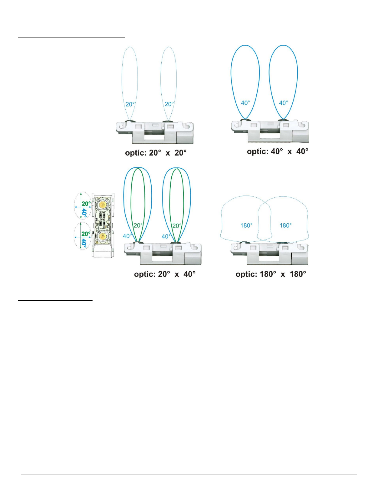
POLYOPTIKTM BEAM ORIENTATION
TM
Architectural Lighting Applications Installation Guide
LOCATION DEFINITIONS
DRY LOCATION
“A location not normally subject to dampness, but may include a location subject to temporary dampness, as in the case of
a building under construction, provided ventilation is adequate to prevent an accumulation of moisture.” (UL Standard 1598,
publication of 2008)
DAMP LOCATION
“An exterior or interior location that is normally or periodically subject to condensation of moisture in, on, or adjacent to,
electrical equipment, and includes partially protected locations.” (UL Standard 1598, publication of 2008)
It includes exterior locations such as under canopies, marquees, roofed open porches and similar locations. This also includes
interior locations subject to moderate degrees of moisture, such as some basements, some barns and some cold-storage
warehouses. Locations sheltered from the weather are considered damp locations.
WET LOCATION
“A location in which water or other liquid can drip, splash, or flow on or against electrical equipment.” (UL Standard 1598,
publication of 2008)
This also includes outdoor locations, which are any location exposed to the weather. Locations sheltered from the weather
are not considered outdoor locations. Conductors exposed to direct sunlight shall bear the mark “SUN RESISTANT”, “SR”, or
similar or be listed as being sun resistant if they don’t bear such marking.
Specifications are subject to change without notice. (Technical bulletin #34)
© HEICO lightingTM 2013 – All rights reserved. Made in Canada. 21/25
Page 22
HEICO lightingTM Contactless LED System Polyoptik
TM
Architectural Lighting Applications Installation Guide
POWER SUPPLY ELECTRICAL CONNECTION IN DRY OR DAMP LOCATIONS
1. Installation shall be done in accordance with the national electrical code and any other electrical code applicable
in your area. Also follow local electrical code ordinances when applicable.
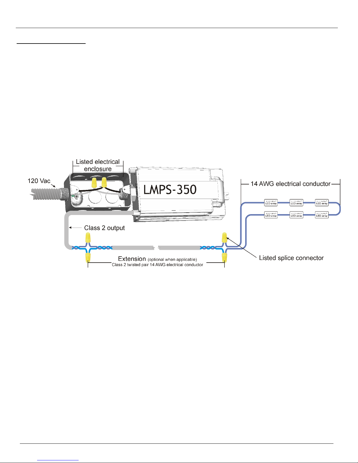
2. A listed electrical enclosure approved for the purpose shall be used for the LMPS primary connection.
3. Power supplies and electrical boxes shall be adequately supported, plumb and true and firmly secured in place with
appropriate fasteners.
4. Adequate spacing and airflow shall be provided in between transformers and surrounding materials.
5. Power supplies shall be oriented or protected in a way that will not let condensing water accumulate in the
enclosure.
6. All wire and splice connectors shall be suitable for the temperature conditions and locations where installed. Splices
shall be kept to a minimum.
7. The Class 2 circuit shall be physically separated from other circuit types.
8. Use #8 fasteners to secure the power supply and the electrical box in place.
9. If more than one (1) LMPS is used, keep a spacing of at least one (1) inch (25.4 mm) between each LMPS.
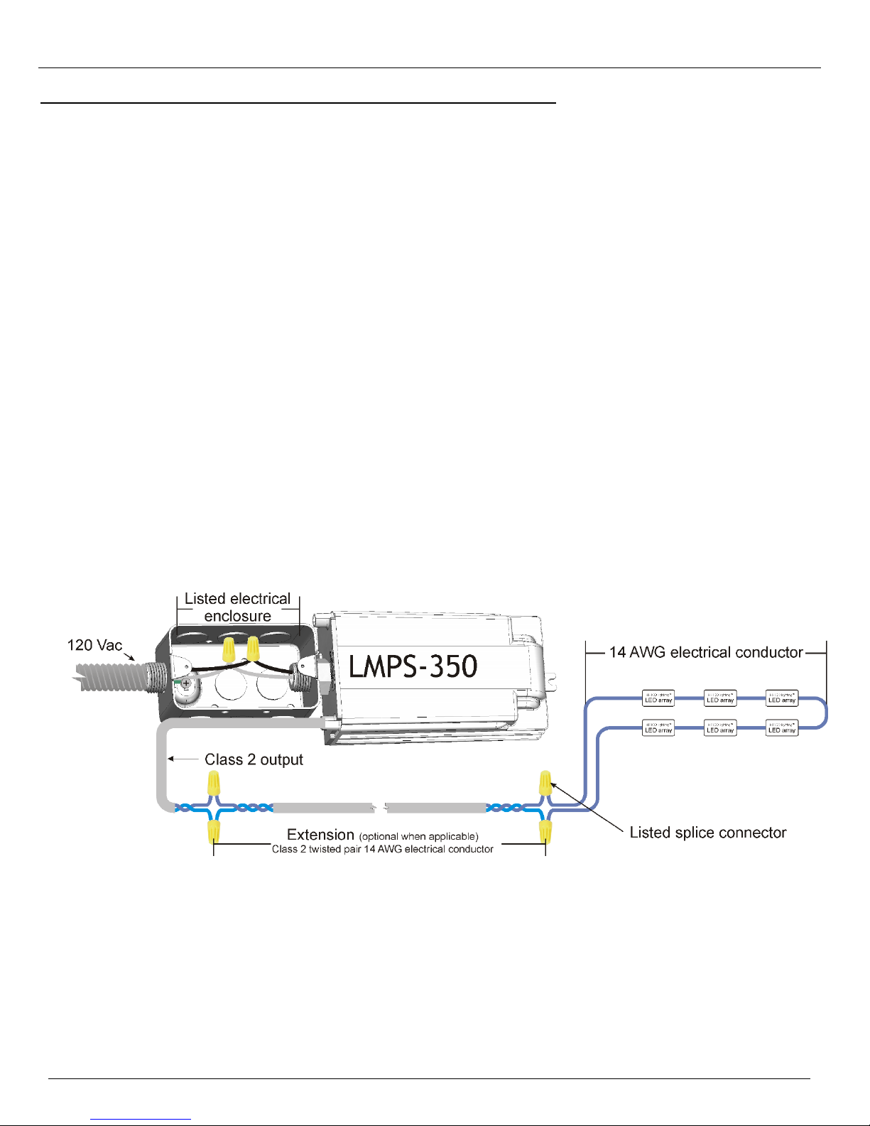
10. If the Class 2 feeder circuit needs to be extended between the LMPS and the LED arrays, use twisted pair cable type
CL2 14 AWG or better, listed for the applicable environment (figure 11). Substitutions according to NEC table
725.154(G) and CEC article 16.210, 16-222, table 19 are permitted (also refer to CEC Appendix B).
Permitted substitutions for CL2 wires are: CMP, CL3P, CL2P, CMR, CL3R, CL2R, CMG, CM, PLTC, CL3.
11. For more details refer to the LMPS-350, LMPS-DC350, LMPS-750 specification sheets (documents 11126.007.G1,
11978.002.G1 and 11126.003.G2)
Figure 11: Electrical connections for installation in dry and damp locations
(twisted pair extension and LMPS-350 shown, others are similar)
Specifications are subject to change without notice. (Technical bulletin #34)
© HEICO lightingTM 2013 – All rights reserved. Made in Canada. 22/25
Page 23
HEICO lightingTM Contactless LED System Polyoptik
TM
Architectural Lighting Applications Installation Guide
POWER SUPPLY ELECTRICAL CONNECTION IN WET LOCATIONS
1. Installation shall be done in accordance with the national electrical code and any other electrical code applicable
in your area. Also follow local electrical code ordinances when applicable.
2. A listed electrical enclosure approved for the purpose shall be used for the LMPS primary connection.
3. Power supplies and electrical boxes shall be adequately supported, plumb and true and firmly secured in place
with appropriate fasteners.
4. Adequate spacing and airflow shall be provided in between transformers and surrounding materials.
5. Power supplies shall be oriented or protected in a way that will not let condensing water accumulate in the
enclosure.
6. All wire and splice connectors shall be suitable for the temperature conditions and locations where installed.
Splices shall be kept to a minimum.
7. In wet locations the power supply shall be installed in an appropriate location and in a listed electrical enclosure
approved for the purpose (examples: NEMA 3, 3R, 3S, 3X, 3RX, 3SX or 4).
8. The Class 2 circuit shall be physically separated from other circuit types.
9. Use #8 fasteners to secure the power supply and the electrical box in place.
10. If more than one (1) LMPS is used, keep a spacing of at least one (1) inch (25.4 mm) between each LMPS.
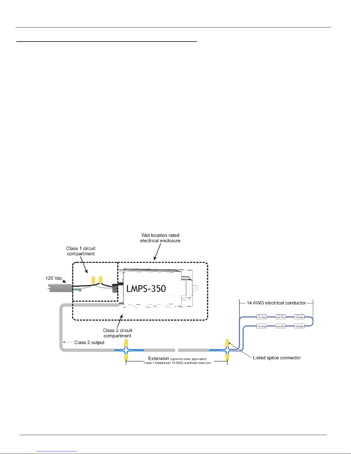
11. If the Class 2 feeder circuit needs to be extended between the LMPS and the LED arrays, use twisted pair cable
type CL2 14 AWG or better, listed for the applicable environment (figure 12). Substitutions according to NEC table
725.154(G) and CEC article 16.210, 16-222, table 19 are permitted (also refer to CEC Appendix B).
Permitted substitutions for CL2 wires are: CMP, CL3P, CL2P, CMR, CL3R, CL2R, CMG, CM, PLTC, CL3.
12. For more details refer to the LMPS-350, LMPS-DC350, LMPS-750 specification sheets (documents 11126.007.G1,
11978.002.G1 and 11126.003.G2)
Figure 12: Electrical connections for installation in wet locations
(twisted pair extension and LMPS-350 shown, others are similar)
Specifications are subject to change without notice. (Technical bulletin #34)
© HEICO lightingTM 2013 – All rights reserved. Made in Canada. 23/25
Page 24
HEICO lightingTM Contactless LED System Polyoptik
TM
Architectural Lighting Applications Installation Guide
ON-SITE INSTALLATION
1. Test the complete area either as a whole or in sections. Verify that illumination is uniform. If applicable, correct
any seen problems.
2. Turn off power before installation, inspection, repair or removal.
3. Use the appropriate extension wire where applicable.
4. Connect the different areas to the power supplies according to the provided layout.
5. All sections on the same power supply shall be wired in series (figure 13).
6. Refer to technical bulletin #5 for troubleshooting details.
Specifications are subject to change without notice. (Technical bulletin #34)
© HEICO lightingTM 2013 – All rights reserved. Made in Canada. 24/25
Figure 13: Typical installation
Page 25
HEICO lightingTM Contactless LED System Polyoptik
Factors such as wire construction and the layout and length of the electrical circuit can affect the loading of the power supply. As
those factors are beyond the control of HEICO lightingTM it is the responsibility of the installer to ensure that maximum loading will
not be exceeded.
In wire loop with return configurations the return wire needs to be routed as close as possible from one another and they need to be
tied together at least each foot.
The user is responsible for proper selection of the electrical conductor type that will be used for the specific application; see the
requirements in technical bulletin #27 “Wiring for architectural applications”.
Contact HEICO lighting
TM
for other wire types and distances usage.
IMPORTANT: The user is responsible for the safe electrical and mechanical installation of the power supply and of the suitability
of the wiring system, mounting surfaces and any mounting hardware used. Failure to do so can lead to electrical and mechanical
failure of the system and serious personal injury.
All equipment shall be installed in a neat and workmanlike manner. See NECA 1-2010 standard “Good Workmanship in Electrical
Construction”.
The user is responsible for proper selection of the electrical conductor type that will be used for the specific application; see the
requirements in technical bulletin #27 “Wiring for architectural applications”.
The Class 2 circuit shall be physically separated from other circuit types.
All technical data in this technical bulletin is based on test results and is believed to be correct. However since the end use of HEICO
lightingTM products, usage application and installation, is beyond our control, HEICO lightingTM makes no warranty expressed or implied
as to the fitness of use. Their use shall be solely by the judgment and at the risk of the user notwithstanding any statement in this
technical bulletin.
All equipment shall be installed in a neat and workmanlike manner. See NECA 1-2010 standard “Good Workmanship in Electrical
Construction”.
The user is responsible for proper selection of the electrical conductor type that will be used for the specific application; see the
requirements in technical bulletin #27 “Wiring for architectural applications”.
The modules installed in the same area should have the same bin letter.
For other LED colors, configurations and general information about layouts please contact HEICO lighting
TM
Refer to the product sheet for more information about the
LMPS-350, LMPS-DC350, LMPS-750 power supplies and the VirgoliteTM modules.
CONTACT US!
Loading Warnings
Installation Warnings
General Warnings
TM
Architectural Lighting Applications Installation Guide
Specifications are subject to change without notice. (Technical bulletin #34)
© HEICO lightingTM 2013 – All rights reserved. Made in Canada. 25/25
 Loading...