

HEI GL7101 Datasheet
1
2 3 4 8 7 6 5
Description
The GL7101 is designed for use in earth leakage
circuit interrupters for operation directly off the AC
Line in breakers.
It contains pre regulator, main regulator, after
regulator, differential amplifier, level comparator,
latch circuit. The input in the differential amplifier is
connect to the secondary node of zero current
transformer.
The level comparator generates high level when
earth leakage current is greater than some level.
Feature
•Low Power consumption (PD = 5mW) 100V/ 200V
•100V/200V Common Built-in Voltage Regulator
•High Gain Differential Amplifier
•High Input Sensitivity
•Minimum External Parts
•Large Surge Margin
•Wide Operating Temperature Range
(TA = -30 to 85¡É)
•High Noise Immunity
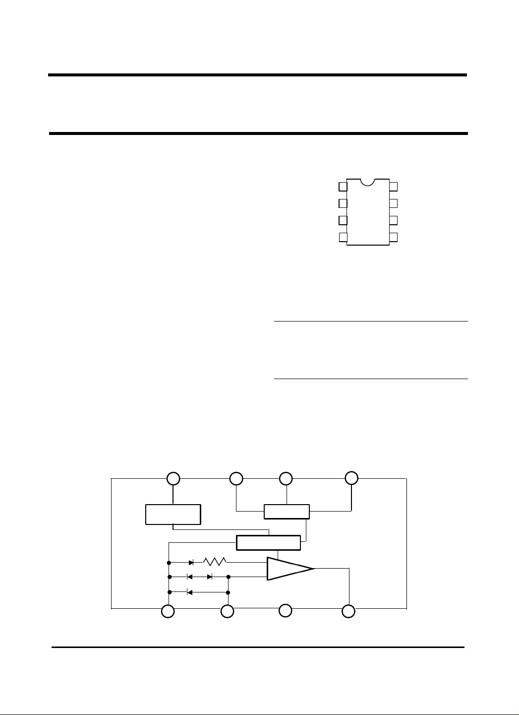
Pin Configuration
Block diagram
V +
8 7 6
Voltage Regulator
1 2
V GND
OS NR
IN
GL7101
GL7101
EARTH LEAKAGE CURRENT DETECTOR
(Top view)
Absolute Maximum Rating (TA = 25¡É)
Supply voltage 20 V
Supply Current 8 mA
Power Dissipation 200 mW
Operating Temperature -30 to 85 ¡É
Storage Temperature -55 to 125 ¡É
Latch
Bias
Amp
3
V
GND
O
1
R
IN
GL7101
D
SC
5
4
O
V+
OS
NR
SC
2
18
-
GL7101
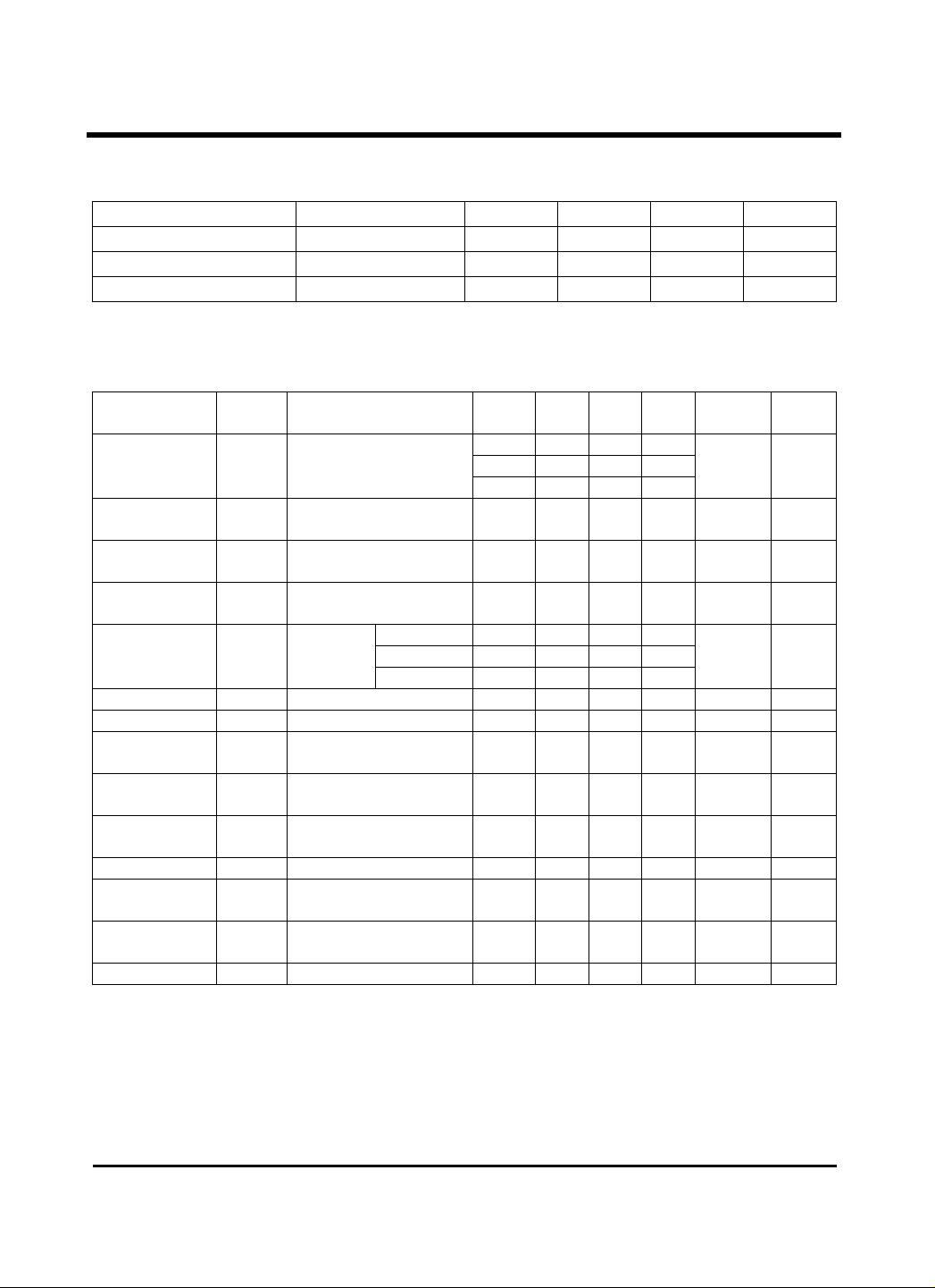
Recommended Operating Condition : Ta = -30¡É to 80¡É
PARAMETER SYMBOL MIN. TYP. MAX. UNIT
Supply Voltage V+ 12 V
VS-GND Capacitor CVS 1 µF
OS-GND Capacitor COS 1 µF
Electrical Characteristics
PARAMETER SYMBOL CONDITIONS
Supply Current 1 IS1 V+=12V, VR-VI=30mV
*
Trip Voltage VT V+=16V, VR-VI=X
Differential Amplifier
Output Current 1
Differential Amplifier
Output Current 2
Output Current IO
SC On Voltage V
S
Input Current ISC ON V+=12V 25 - - 5
C
Output "L" Current I
Input Clamp Voltage VIC V+=12V, VIC=20mA
Differential Input
Clamp Voltage
Max. Current voltage VSM ISM=7mA 25 20 - 28
Supply Current 2 IS2 VOS=0.5V, VR-VI=X
Latch Circuit Off
Supply Voltage
Response Time TON V+=16V, VR-VI=0.3V 25 1 - 4
*
A: 9 ~ 12.55 B: 11.5 ~ 15.5 C: 14.5 ~ 18
I
I
V
V+OFF 25 0.5 -
TEMP
(¡É)
V+=16V, VR-VI=30mV
TD1
TD2
SC
OSL
IDC
VOD=1.2V
V+=6V, VR-VI=short
VOD=0.8V
VSC=1.4V
VOS=0.8V
ON V+=16V 25 0.7 - 1.4
V+=12V, V
I
=100mV
IDC
ISI=580 µA -30
ISI=530 µA 25
ISI=480 µA 85
0.2V
OSL
MIN. TYP. MAX UNIT
-30 - - 580
25 - 400 530
85 - - 480
-30
9 13.5
85
25 -12 - -30
25 17 - 37
-200
-100
-75 -
-30
200 - -
85
-30
4.3 - 6.7
85
-30
0.4 - 2
85
-30
85
-
- - 900
µA 1
mV(rms)
µA 3
µA 4
µA 5
V 6
µA 7
µA 8
V 9
V 10
V 11
µA 12
V 13
ms 14
TEST
CIRCUIT
2
 Loading...