

HEI GL3820 Datasheet
GL3820
1
1 2 3 4 5
7
8
GND
Ω
VIDEO INPUT
NC
EXTERNAL
VIDEO OUTPUT
External
1 VPP
Video
Video
Ω
Switching Input
Ω
Ref.
8 3 7 6 2 1 5
GL3820
Description
This integrated circuit provides all video
switching allowing connections between the peri
TV plug and video sections in the TV set.
Features
• 1 Video Output 75Ù – 1 VPP No Switched
• 1 Switched Video Output 2 VPP
• Video Cross Talk : 50 dB Typical
• Short Circuit Protection of Inputs and Outputs
• Clamped Video Inputs
Maximum Ratings
RATING SYMBOL VALUE UNIT
Supply Voltage Vcc 18 V
Operating Temperature
with Load > 150Ω
with Load = 75Ω
Junction Temperature Tj -40 to + 150
Storage Temperature T
Minimum DC Load Resistor P6
Minimum DC Load Resistor P2
T
opr
stg
600
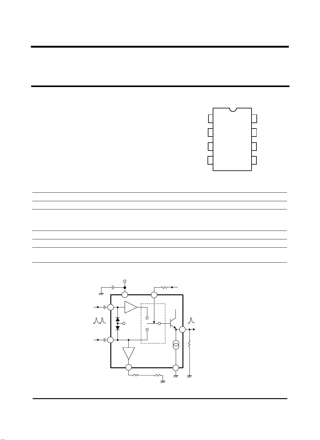
Pin configuration
75
INTERNAL
-10 to + 100
-10 to + 70
-40 to + 150
75
GL6850
VCC
SWITCHED
6
SWITCHING
INPUT
¡É
¡É
¡É
Ω
Ω
Typical Application and Test Circuit
Note : We advice to protect the 75Ω output through a 75Ω resistor for supply voltage upper than 9 V.
Video
Input
Coming
from
TV
2 VPP
V
Video 1 VPP
CC
. 0 or no connected = Video TV
. > 7V = external video
G = 2
(low
impedance)
G = 1
75Ω
75Ω
10k
2mA
600
2 V
PP
2
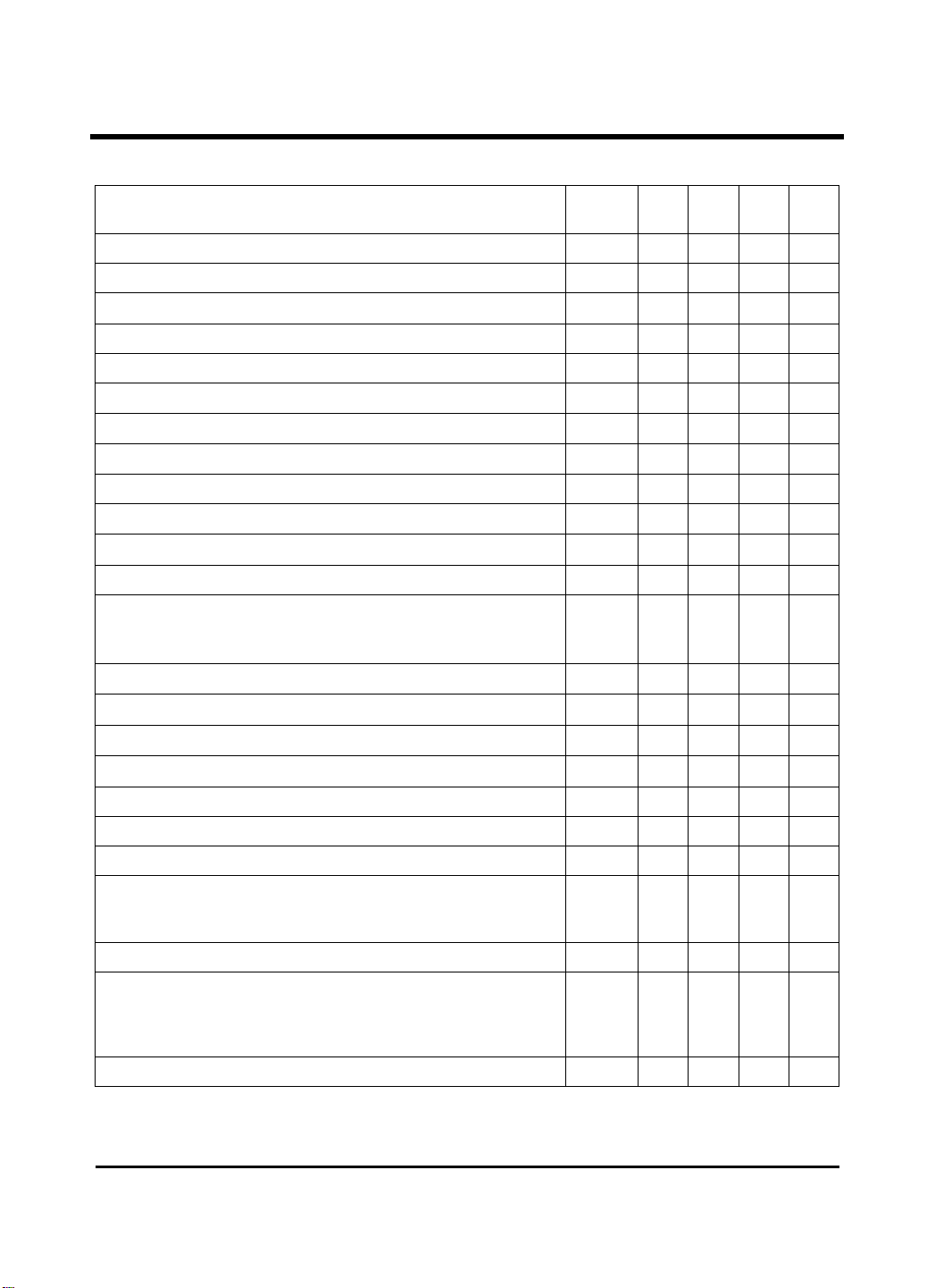
Electrical Characteristics : Ta = + 25¡É, VCC = 9V (unless otherwise noted)
CHARACTERISTIC SYMBOL MIN TYP MAX UNIT
Supply Voltage Range VCC 8 - 14 V
Supply Current (no load on pin 2 and pin 6) I
Supply Current (with 75Ω between pin 2-1, with 600Ω between pin 6-1)
Total Power Dissipation with Load P
Internal Video Input Swing from PIF (positive video) - - - 4.5 V
Internal Video Input Impedance (positive video)
External Video input Swing (positive video) - - - 2 V
External Video Input Impedance (positive video)
Switched Video Output Swing - - - 4.5 V
Switched Video Output Dynamic Impedance
Switched Video DC Output Voltage (sync. Pulse level, note) (600Ω)
Switched Video Band Width (- 1 dB) - 6 - - MHz
Switched Video Output Gain
Pin 6 – Pin 8 (gain with 600Ω load)
Pin 6 – Pin 3 (gain with 600Ω load)
GL3820
CC
I
CC
tot
- 50 - -
- 50 - -
- - 10
- 105 1.8 2.2 V
- + 5
- - 20 mA
- 40 - mA
- 450 - mW
+6
+7 0 DB
- 1
-0.5
kΩ
kΩ
Ω
PP
PP
PP
External Video Output swing( with 150Ω load)
External Video Dynamic Output Impedance
External Video DC Output Voltage (sync. Pulse level, note) (150Ω)
External Video Output Gain (pin 2 – pin3 gain with 150Ω load)
- - 2 2.2 V
- - 10 -
Ω
- 1.5 1.8 2.2 V
- -1.8 -1 -0.4 dB
Switching Input Unactive Low Level or Unconnected Pin (TV receiving) - 0 - 3 V
Switching Input Active Level (ext. receiving) - 7 - V
CC
V
Switching Input Impedance - 10 - - kÙ
Video Rejection between Two Inputs
0 to 5 MHz
1kHz
-
-
-50
-
-50
-
- - dB
Differential Group Delay - - 15 - ns
Linearity Distortion
Luma
Chroma
Intermodulation Luma - Chroma
-
-
-
2
2
5
-
-
-
%
Supply Voltage Rejection (1 kHz) - 40 50 - dB
Note : Use a video signal with a synchro pulse in order to make the clamp work in a correct way (75Ω to
the ground and 10ì F in series).
 Loading...