

Page 1
EN
Operation Manual (original language)
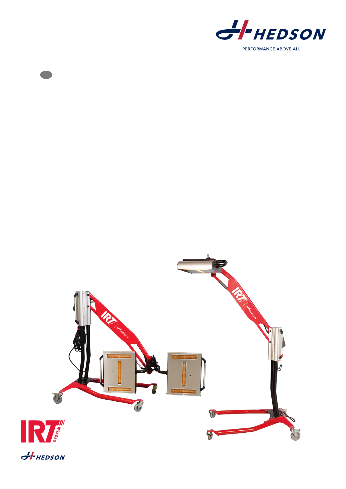
IRT Dryer Siemens
Leading Edge Protection
196349 rev 1 ©Hedson Technologies AB 2018
Page 2
TABLE OF CONTENTS
1. Safety instructions ........................................................3
2. Intended use of the product ......................................4
3. Product description .....................................................4
4. Instructions to the owner ............................................5
5. Assembly instruction ...................................................5
6. Basic instruction for operation ...................................5
7. Program mode .............................................................8
8. Extended usage information ......................................9
9. Settings mode .............................................................9
10. Maintenance and Service ........................................ 12
11. Spare parts................................................................. 14
12. Safety inspections ..................................................... 14
13. EC Declaration of conformity ................................. 16
14. Pneumatic and Electrical diagrams ........................ 17
15. Weights and Dimensions ......................................... 17
16. Trouble shooting ....................................................... 18
EN
2
196349 rev 1
Page 3
1. Safety instructions
1.1 Operator´s duty of care
The IRT Siemens Leading Edge Protection Dryer is
designed and built after a hazard assessment was considered and following careful selection of the required
harmonized standards as well as additional technical
specifications. It corresponds to the current state of technology and guarantees the highest safety level.
However, this safety level can only be reached during
practical operation, when all the required measures have
been implemented. Due diligence is required on the
part of the platform operator, to plan these measures
and ensure their implementation.
In particular, the operator must always ensure that:
• the dryer is only used for the intended purpose.
• the dryer is only to be used in a fully functional and
fault-free state and it is to be checked regularly for
operational functionality with special attention paid
to the safety equipment.
• persons are prevented from entering the hazardous
area (space under the IR platform). Maintenance
work is excepted.
• the operating instructions must always be fully legible and available at the dryer operational site.
• the dryer is only used by individuals who have read
and understood the operating manual.
• only adequately qualified and authorized personnel
are allowed to operate, maintain or repair the dryer.
• none of the safety and warning labels on the dryer are
to be removed and all of them must always be legible.
• the personnel are to be regularly instructed in all
relevant questions regarding work safety, environmental protection and the operating manual and
especially the safety instructions contained therein.
• the heater platform must be lowered into its start
position after you have finished working with it.
1.2 Task of the operator
Certain measures are included in the Industrial Safety
Regulations for operators using working equipment in
hazardous areas.
The operator must conduct a risk assessment of the area
in which the working equipment (working platform) is
to be deployed. The hazardous situations that can be
caused when using the working equipment in conjunction with the working materials and the working environment should be recognized and addressed.
The operator must implement the required measures
and select the equipment which is appropriate for the
given workplace conditions and which, if used for its
intended purpose, offer the necessary protection as
regards health and safety.
The operator must apply national directives and standards when conducting the risk assessment and choosing the appropriate equipment.
1.3 Basic safety measures
The IRT Siemens Leading Edge Protection Dryer must not
be exposed to paint fog, sanding dust or solvents, due to
fi re hazard. Furthermore, this will reduce the lifetime of
the dryer. Allow for sufficient cooling time of the dryer.
The distance to the object that is to be dried must be sufficient. Otherwise there is risk for fire or explosion!
Keep all flammable materials in a sufficient distance
from the hot surfaces of the dryer.
• The dryer is only to be moved when the platform is
completely lowered (see 1.4 Hazards).
• Nobody and no objects are to be on the mobile
dryer whilst it is being moved.
• The dryer must always be monitored by the operator
for the entire duration of the moving, lifting or lowering process.
• Parts such as the hoses or air bellows must be protected from damage when working in conditions where
high heat is generated (welding, grinding, etc.).
Abiding by the following regulations is particularly
emphasized:
• The instructions in the operating manual must be followed whenever the dryer is operated.
• Independent operation is only to be undertaken by
a person who is older than 18 and has been trained
in the operation of the dryer.
• The dryer is only to be moved when it is in the start
position (completely lowered) and without anybody
or any load on it.
• Ensure stability and keep sufficient distance from
objects, walls and ceilings! The maximum permissible gradient is 2.5% (1/40, corresponding to 2.5
cm per 100 cm).
• The dryer must be monitored by the operator during
the entire lifting or lowering process.
• Nobody is to stand under the load lifting handling
attachments or in the pivot area of the scissors.
• This dryer is for indoor use only. Outdoor installation
is not allowed!
• The dryer must be inspected by a specialist after
any modifications have been made to the structure
and after maintenance has been carried out on the
load-bearing parts. Modifications and repairs must
be recorded in the master data sheet.
• Climbing on the dryer is prohibited.
• The dryer must not be used as a hoist or a crane.
1.4 Hazards
Tilting
The risks for tilting increases when the platform is in elevated position do not transport the mobile dryer unless
its platform is lowered completely. Small adjustments in
length and sideways can be made in elevated positions
to get the green lights from the distance indicators. All
movements of the IRT Siemens Leading Edge Protection
Dryer are to be made with help of the four handle bars
one at each corner at the base. No adjustments or movement of the dryer are to be made by applying force to
the scissor/lifting part of the mobile dryer or frame with
the IR heaters mounted on the lifting platform.
196349 rev 1
EN
3
Page 4
Fire and explosion.
Do not store, prepare or use solvent-containing materials
within a 5 m/16 feet radius of the mobile dryer. Flammable materials should not be placed close to a drying
device in use.
If you have a distance less than 60 cm/2 feet to the object the temperature might raise quickly and the risk for
fire increases. Never direct the cassette towards highly
combustible materials.
Electrical equipment
The dryer is operated with high electrical voltage, which
can be highly dangerous.
Before accessing live parts, remove the main connector
from the wall socket. Only professional electricians may
have direct access to the electrical components.
If the supply cord is damaged, it must be replaced by
the manufacturer, its service agent or similarly qualified
persons in order to avoid a hazard.
3. Product description
The IRT Siemens Leading Edge Protection Dryer is a
maneuverable infrared dryer.
The infrared drying system is equipped with nine IRT SingleHeaters in a frame mounted on a Herkules pneumatic
lift. Each IRT SingleHeater is equipped with one infrared
(IR) lamp and has a gold-coated reflector. IR lamps are
easily exchangeable and the reflectors are protected
against mechanical damage by a mesh. The design combined with the possibility to linear lifting and lowering,
enables ergonomically drying at various heights from
850 mm to 2650 mm. The lifting and lowering of the IR
platform works solely with compressed air. The roller
system enables the dryer to be positioned precisely and
the integrated brakes stop it from rolling any further and
this increases the overall safety. Operation of the IRT
Siemens Leading Edge Protection dryer is controlled by
an integrated control unit.
WARNING !
Intensive heat radiation. Hands, face and
other parts of the body should be exposed
as little as possible to the heat radiation.
Optical Radiation emission
Category 2 (EN12198)
Siemens Leading Edge Protection Dryer
emits Optical Radiation in form of Infrared
light. Avoid looking directly into the IR
lamps, risk of eye damage. Use IR-protec-
tion glasses.
1.5 Operating personnel requirements
The working platform may only be operated by personnel who have been trained and instructed accordingly
or have been authorized to do so. The personnel must
know the operating manual and act according to it.
The respective levels of authority of the operating personnel must be clearly defined.
Moreover, specific qualifications are required for some
activities; see appendix 1, Manual 761-054_PNTS-77
chapter 6.4.
2. Intended use of the product
This product serves exclusively to accelerate the drying/curing of Siemens Leading Edge Protection. Its site
of use is the preparation area and finishing area. The
product must not be used for other purposes than the
described drying process. The maximum ambient temperature during operation should not exceed 30°C. The
IRT Siemens Leading Edge Protection Dryer must not be
used within a distance of 5 m from spraying activities in
order to avoid explosion risk. No people are allowed to
be present beneath the platform during the operation.
Working under the raised working platform and during
its lifting and lowering movements is not permitted.
3.1 Particular advantages
3.1.1 Higher quality
The short-wave IR curing enables the coating to be cured
from the inside outwards. This prevents solvents to be
trapped inside the coating and ensures a fast and high
quality curing.
3.1.2 Regulated temperature
The dryer has a pyrometer which carefully controls
temperature of the object. The computer does not only
measure the maximum allowed temperature but also the
temperature raise. It ensures that the programmed drying/curing temperature is maintained, thereby achieving
optimum curing, without risk for “over burning”.
3.1.3 Hi-tech shape of reflectors with short wave IR
By using short-wave technology and gold-coated reflectors with a high tech shape, important advantages are
achieved. Firstly, by radiating only the needed areas
and not heating any air, a lower energy consumption is
achieved. Secondly, a more uniform surface temperature
is obtained by distributing the energy evenly. Thirdly, a
larger drying surface is achieved. Fourthly, less radiation
outside the curing area.
3.2 Technical data IR heating system
All dryers emit short-wave IR-radiation with a peak at
1120 nm.
Voltage 380–420V 3~PE
Frequency 50–60 Hz
Current 40 A
Power 27 kW
Fuse** 60 A
Amb. temp. Max. 30°C
Noise level <70 dB (A)
* MCB (Minature Circuit Breaker) type C or D.
Normal fuse type slow.
** The dryer shall be operated with the recommended fuse rating.
Weights and dimensions, see 17.
4
EN
196349 rev 1
Page 5
4. Instructions to the owner
The owner of the dryer must produce clear operating
instructions, adapted to local site conditions, and make
these available to all users who have to observe these
operating instructions.
This dryer is not intended for use by persons (including
children) with reduced physical, sensory or mental capabilities, or lack of experience and knowledge, unless they
have been given supervision or instruction concerning
use of the dryer by a person responsible for their safety.
No additional equipment is to be attached to the dryer.
Dispose of used items at the nearest environmental pro-
tection facility for recycling.
For safety reasons the infrared dryer must be supplied by
recommended maximum fuse, see table in chapter 3.2.
5. Assembly instruction
The IRT Siemens Leading Edge Protection Dryer is delivered fully assembled and need only air and electricity
to work but when installing the dryer it is imperative that
the following safety instructions are always observed – it
helps prevent life-threatening injuries, damage to the
machine and other property.
Only qualified persons heeding the safety instructions
are permitted to carry out the installation work.
• The dryer must be examined for any possible transport damage before starting the installation work.
• Ensure that only authorized persons are in the working area and that no other persons are at risk due to
the installation works.
• All machine connections (hoses) must be laid so that
there is no risk of tripping over them.
• Also read the General Safety Instructions chapter.
• Unauthorized tampering invalidates the guarantee.
5.1 Environmental installation conditions
Siemens Leading Edge Protection Dryer is only suitable
for use in enclosed, dry and covered premises.
Ensure that there is sufficient space away from objects,
walls and ceilings before installation.
It is important to ensure that the minimum distances (according to the relevant national regulations and workplace regulations) to the hall walls or other equipment,
escape routes, etc. are kept to ensure safe working.
The floor should be flat with a maximum gradient of
2.5% (1/40, i.e., 2.5 cm per 100 cm) and the load capac-
ity of the floor must be able to bear the permissible total
weight of the dryer. The operator of the dryer is responsible for selecting a suitable installation site.
The dryer is only to be used at sites with temperatures
ranging from 10°C to 50°C.
An adequately sized compressed air connection (hose
1/2 “, Pmax = 8 bar) must be provided.
Use dehumidified, non-lubricated compressed air only.
A filter regulator must only be installed in the air supply
line (air filter and water separator).
6. Basic instruction for operation
Move the dryer to the site where you want to use it. This
can only be done from the shorter side of the undercarriage with help of a fork lift or by pushing or pulling in
the four handlebars one at each corner of the mobile
dryer. For manual movement it is recommended to be at
least two persons to maintain safe and ergonomic work.
The dryer is only to be moved when it is in the start position (completely lowered) and without anybody or any
load on it.
Small adjustments length and sideways can be made
in elevated positions to get the green lights from the
distance indicators. All movements of the IRT Siemens
Leading Edge Protection Dryer are to be made with help
of the four handle bars one at each corner at the base.
No adjustments or movement of the dryer are to be
made by applying force to the scissor/lifting part of the
mobile dryer or frame with the IR heaters mounted on
the lifting platform.
Stop the undercarriage from moving by locking the
brakes on the four rollers. Check that the brakes are
working!
Watch your step carefully and keep a safe distance from
other objects, escape routes, walls and ceilings.
The maximum permissible gradient is 2.5% (1/40, corresponding to 2.5 cm per 100 cm).
Use a coupling connector to connect to the line’s quickrelease coupling (Pmax = 8 bar/on-site supply). The
coupling must lock into place!
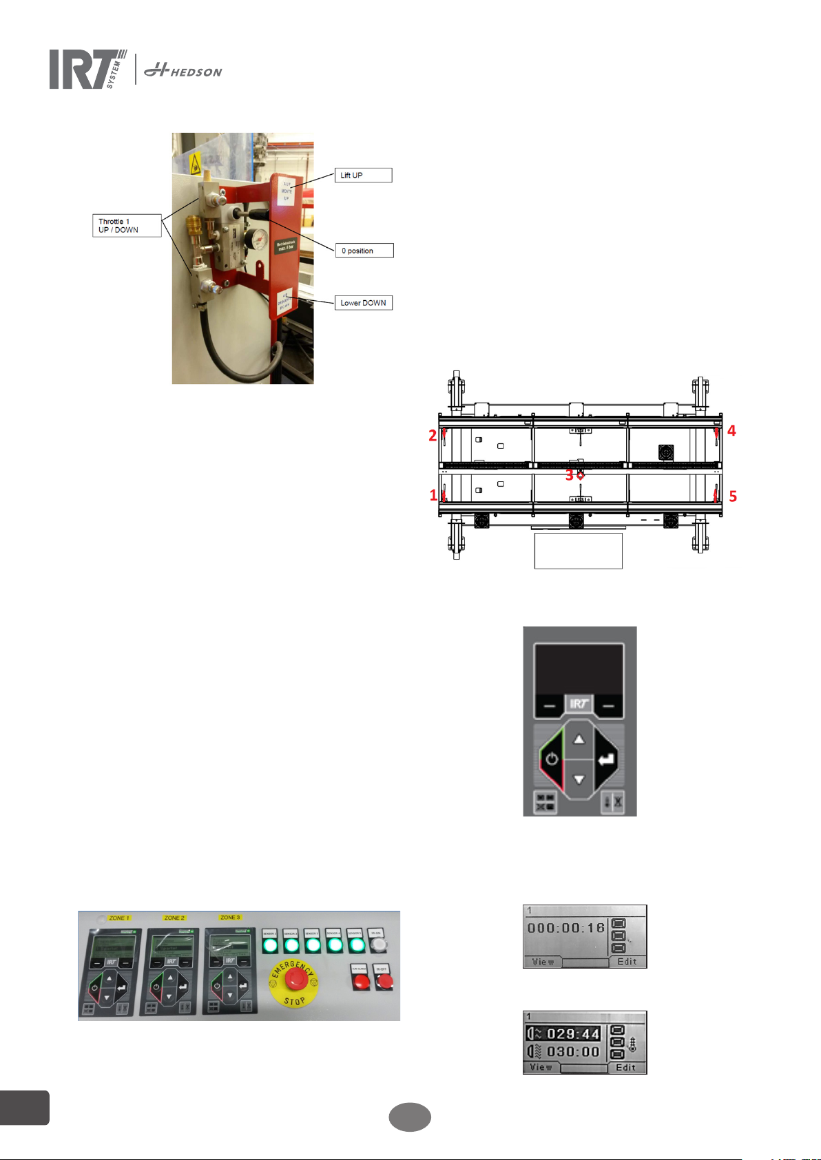
The dryer has an EMERGENCY-RELEASE switch. The
platform can be lowered by a person standing next
to the platform in the case of a control valve failure. In
this case, the emergency release switch must be held
pressed down until the start position is reached.
Proceed as follows to lift the IR platform:
Open the shut-off valve on the hand lever valve. Press
the hand lever valve upwards and hold it until there until
the required lifting height or the end position is reached.
Take note of the hazardous areas whenever possible.
Releasing the hand lever valve automatically returns the
valve back to the 0 position and the lifting process is terminated immediately. The lifting process stops automatically when the maximum lifting height is reached.
Proceed as follows to lower the IR platform:
Check the hazardous area to make sure no persons or
objects are in the dryer´s working area.
Press the hand lever valve downward and hold it there
until the start position is reached or the lowering process
is automatically terminated. Take note of the hazardous
areas whenever possible.
Releasing the hand lever valve automatically returns the
valve back to the 0 position and the lowering process is
terminated immediately.
Close the shut-off valve on the hand lever valve before
leaving.
196349 rev 1
EN
5
Page 6
Tips: When starting in the lowest position, the lift can
jump a small distance; fine tuning of height is done
instead by lowering the lift to the right position
6.1 Start up
Carry out the following functional checks before use:
• Ensure that no persons or objects are in the working
area of the dryer.
• Ensure that the compressed air supply and electricity is available.
• Shift the switch lever on the pneumatic control panel
to the lift-UP position until the IR platform reaches
the upper stop position.
• Shift the switch lever on the pneumatic control panel
to the lower-DOWN position until the IR platform
reaches the lower stop position.
• Repeat the lifting and lowering movements several
times.
Also, see Chapter 1 Safety Instructions.
6.2 Compressed air connection
Use a coupling connector to connect up to the line’s
quick-release coupling (R ½“ on-site supply). The coupling must lock into place!
Use dehumidified, non-lubricated compressed air only.
Connect the air supply line before starting work and
disconnect again after leaving the working platform.
A filter regulator must be installed in the air supply li ne
(air filter and water separator).
6.3 Operation of the IR lamps
Control panel
of distance sensors are disturbed by the infrared light.
Note the lights are only an aid to find the right position
towards the object it is possible to start the IR lamps
although the lights are not green.
2. Start of the fully automatic IR program. Infrared
lamps turn off automatically after the drying period ends.
3. Infrared lamps, manual stop of process.
4. Indicator light that indicates that a process failure
occurred. The alarm only stops the actual zone that has
the failure. See also Appendix 1.
5. Emergency stop IR lamps.
6. For daily use are not needed three touch control
panels used. See Chapter 6.4 to 9 for the setting of the
control system and temperatures.
Distance sensor and zone location
6.4 Keyboard
Software defined button
Confirmation choices
Start/
Stop
1-3 outputs
Software defined button
Cancellation choices
Enter
Temperature control
On/Off (Optional)
6.5 Display
Active program without pyrometer
6
1. The lights turn green when the correct distance
obtained between IR lamps and object. This distance
must be checked before the IR lights turned on. During
operation with IR lamps, these lights may blink because
Flash off – active
Full bake – inactive
Confirmation choices
Flash off – active
Full bake – inactive
Confirmation choices
EN
Temperature control
activated
Edit temperature
Active program with pyrometer
Temperature control
activated
Edit temperature
196349 rev 1
Page 7
6.6 Program mode
This mode is for your everyday use. It helps you run the dryer with pre-installed programs and edit program settings.
To enter the program mode, turn
the main switch on
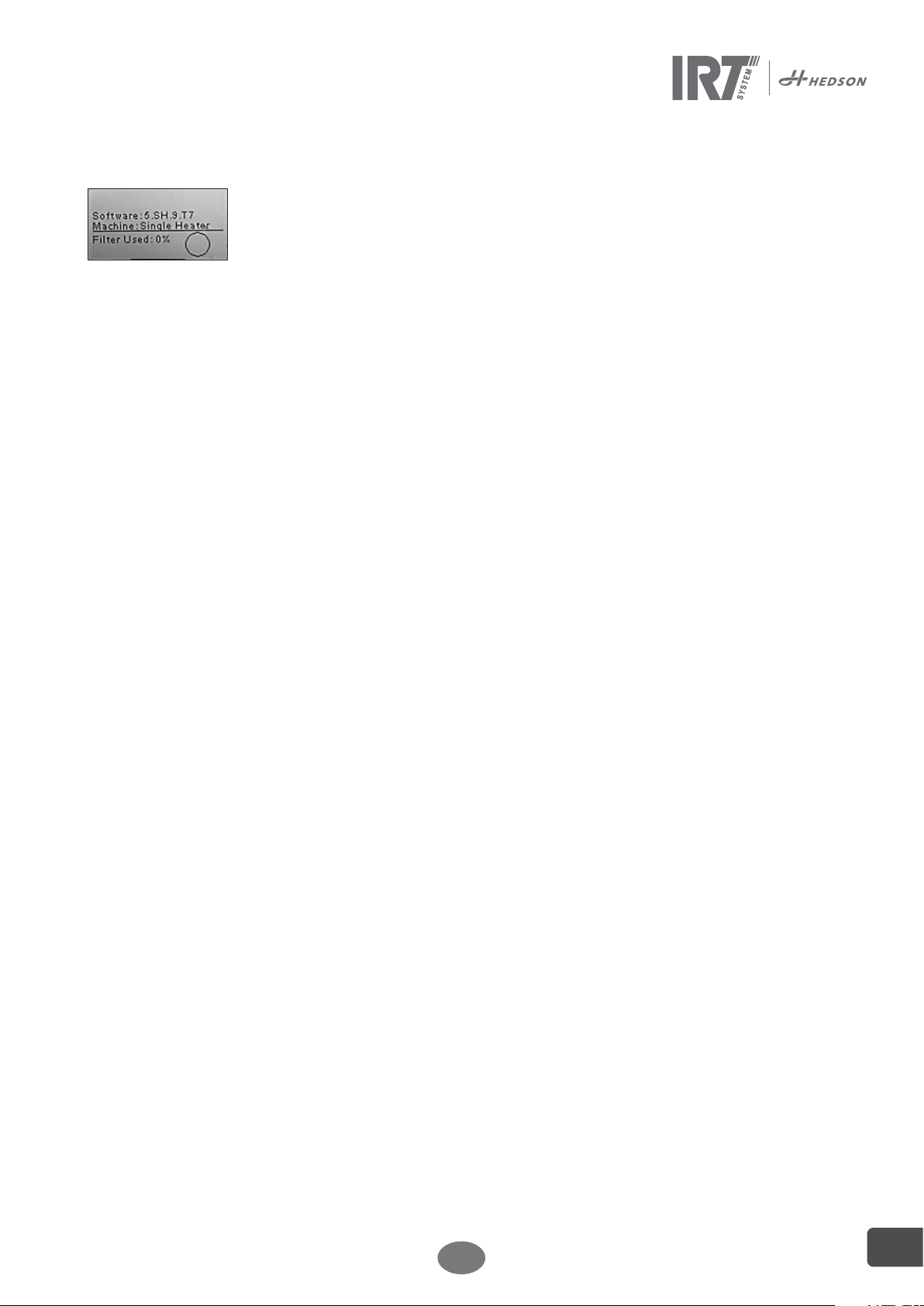
When you start the dryer, an information screen will
appear for two seconds. By pressing the confirmation
or cancellation button this information will show until
released. The diagram shows cassette filter usage and
notifies when it’s time to change filter. To replace filter,
see chapter 10.
6.7 Settings mode
The Settings mode enables you to change advanced system parameters. Thanks to our advanced control system
in this dryer, there are many settings that can be altered.
This is normally not a part of the everyday usage.
To enter the settings mode, press both arrow keys when
you turn the main switch to position 1.
Read chapter 9 for more information.
6.8 Program interruption
To stop the heating before the automatic end of the
program (Continues mode off), press the Start/Stop button. If external Start/Stop, press the external Start/stop
button.
Note! For the IR lamps to cool down and thereby last
longer, the fans continue to go and turn off automatically
with 3 minutes delay.
6.9 Tempertaure switches
There is a temperature sensor on the circuit board which
you can read in ºC or ºF depending on your settings.
There is a temperature switch on each cassette and if it’s
tripped the display will show the value 500.
6.10 Edit settings during process
To edit power level or temperature press Edit and password, arrow up/down then press Save.
196349 rev 1
EN
7
Page 8
8
7. Program Mode – General rules for navigation in the software
– The display shows software defined options in the bottom corner fields.
– To adjust the values, use the arrow keys.
– To move to previous display without saving, press cancel.
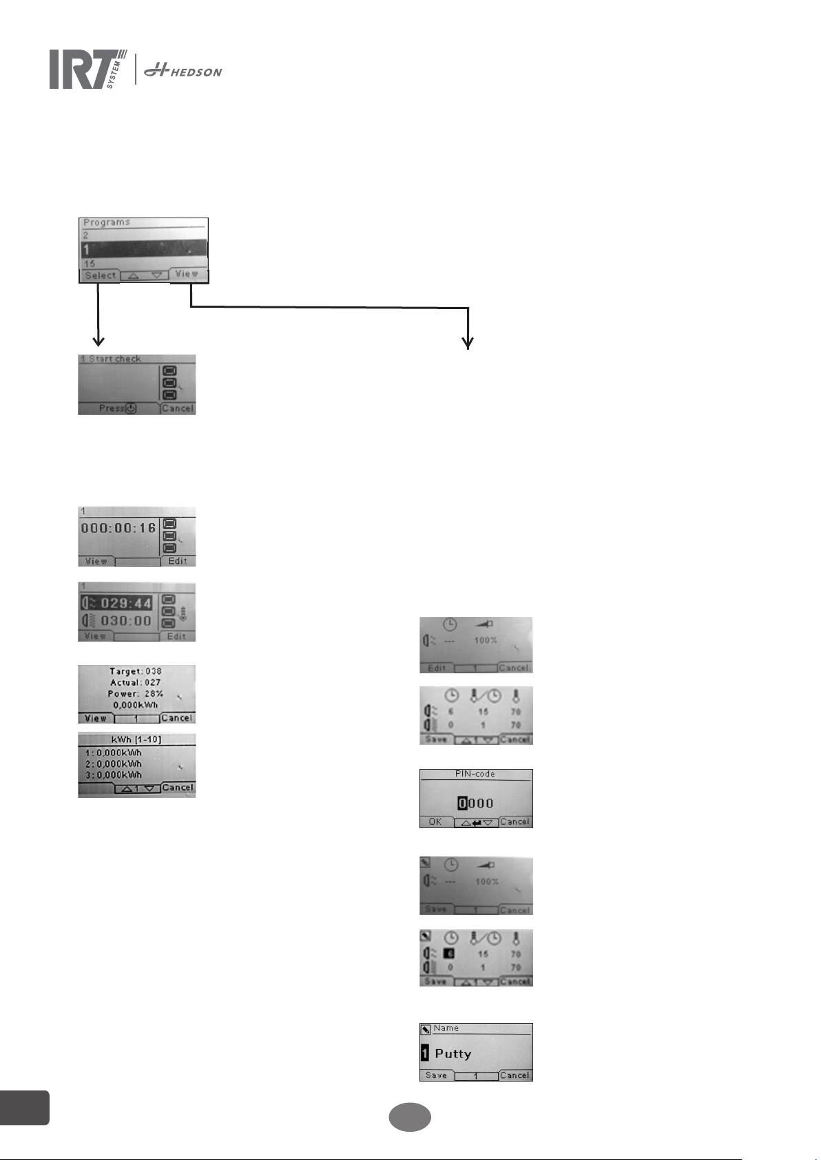
7.1 Basic navigation
There are 15 predefined programs. All 15 programs have editable positions, names and
drying parameters.
Scroll up or down using the arrow keys, press select to run the program or view to edit.
ambient temperature. Reset by pressing on
the indicated reset button on the display.
2. Box Temperature Alarm
When the temperature exceeds 70ºC at the
circuit board this alarm will show in the display
after the drying operation is finished. If this
happens check the cooling system of the control unit (fan, filter or ambient temperature)
3. Paint Temperature Alarm
Also called Process alarm, see 8.2. Option if
pyrometer is used.
4. Filter Alarm
When the maximum operation time for the
filter is reached, there will be a warning
message stating this. The default time is 400
hours, to change this see 9.4.11. To reset the
alarm, see 9.4.18.
5. Phase Alarm
There are two possible sources:
1. Disturbance in main electrical supply:
Check incoming electrical supply all phases.
2. Internal fuse tripped: Check fuses and
reset if tripped, see 11.
To reset the alarm press reset indicated on
the display or restart the dryer.
Stop or cancel
returns to 7.1.
Power control
7.2 Run
7.2.1 Start check
Use the cassette selection button on the
keyboard to alter between one, two or three
active cassettes. Use the temperature control
button to turn on/off the temp. control (only
possible on when temp. control is included
in the unit), see 8.1
Optional: The distance is indicated on the
display as numbers or by the texts ”Too
Close”, ”Too Far” or ”Correct” (only appears when start on Keypads). If measuring
fails "Check distance manually" appears.
7.2.2 Start drying
Press start to begin the drying sequence.
Power control, continues mode on: the
time will start counting.
Temperature control, continues mode
off: the remaining time of the flash off
will start counting down. When the flash
off is finished, the program automatically
changes to full bake mode.
.
7.3 Edit
Temperature control
7.2.3 Program values
Press view and the screen shows the
values for power (0–100 % of machine
capacity) and energy consumption of
current drying process. When the unit
is temperature controlled: both a target
and an actual value is given.
Note! An inactive temperature control
does not show temperature values.
Press view again and total energy consumption
per drying process is shown for the last 10 runs.
Power control
Temperature control
7.2.4 Drying complete
When flash off and full bake times have
expired the software returns to 7.1.
Note! To extend the lifetime of the lamps, the
ventilators will continue to run for cooling. After three minutes they turn off automatically.
Note! When the drying program is completed, the temperature control will automatically
reactivate (if included in the unit).
Power control
7.2.5 Alarm functions
There are five possible types of alarm:
1. Cassette Temperature Alarm
If a temperature switch is triggered in a cassette the drying operation will be terminated and there will be an alarm. In the display
there will be a warning message stating
that the temperature in the cassette is too
high. A value of 500 is also showing beside
the cassette where the switch is triggered. If
this happens; Check fans, filters, hoses and
Temperature control
7.3.1 Properties
The values of the chosen program will show
on the display. Press Temperature control to
switch between properties with and without
temperature control. A change in either prop-
erty is independent of the other one. See 8.1.
7.3.2 PIN Code
Use the arrow keys to set the correct digit. Press
enter to confirm and to edit the second, third and
fourth digit of the advanced PIN code.
Note! An entered PIN code is valid for all
entries until the main switch is turned off. See
8.2 for advanced PIN code.
7.3.3 Edit program parameters
When marked, change the value of the
parameters with the arrow keys. Press enter to
change the next value and so on. Pressing en-
ter for the last value directs the user to editing
of program position and name. Press cancel
to exit without saving any parameters. It is
also possible to change final temperature and
power level when the unit has been started.
Press edit and change value, then save.
7.3.4 Edit program position/name
When marked, change the program number
with the arrow keys. Press enter to confirm
and to edit the next symbol.
Note! Changing the number will also change
the program position in the program list.
EN
.
196349 rev 1
Page 9
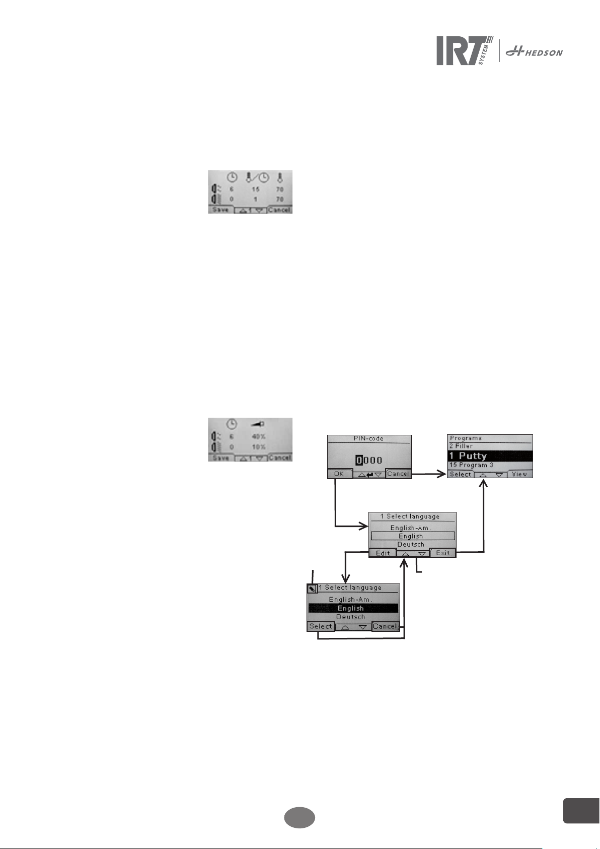
8. Extended usage information
9. Settings Mode
8.1 Temperature control (OPTION)
The dryer is equipped with an automatic temperature
control. This enables optimum drying/curing results
within the shortest possible time.
The properties when the temperature control is on are:
a. minutes
b. temperature increase/minute
c. max allowed temperature
The temperature control (pyrometer) measures the
average temperature over a surface. The laser pointer
indicates where the distance check is made. This pointer
is close to being in the centre of the temperature measurement also.
In settings mode, the short and long limit for a “correct”
distance measurement can be adjusted. Default correct
distance is between 55 and 65 cm.
Note! The temperature is measured as an average of the
measured surface (default diameter value 30 cm, other
optics are available). Make sure to have the measuring surface placed correctly. Make sure that you don´t
measure the temperature on glass, tyres or outside the
object. Otherwise, the result between the programmed
temperature values and actual values may differ. This
may lead to unsatisfactory results and if the process
alarm is activated it will stop the drying/curing.
With the temperature control deactivated, the program
properties are:
a. minutes
b. percent power of max possible
The program settings with or without the temperature
control activated are working independently of each
other.
8.2 Process alarms (OPTION)
To notice temperature deviations, the dryer is equipped
with a process alarm. If the difference between the
current temperature and the requested temperature is
more than 30ºC (adjustable, see 9.4.28), the message
“Warning! Process error” appears in the display and the
dryer switches off automatically. This warning has to be
acknowledged by pressing enter. By doing this, the program is terminated. In case of process alarm, check if the
temperature measuring device (pyrometer) is aligned
correctly on the surface to be dried and that it is not
registering unwanted material temperatures.
Attention! The process alarm function is not activated
when dryer is delivered.
Please see chapter 9.4.3 for activating.
8.3 External start and stop
There is an input in this SingleHeater Control Unit to
enable a remote start and stop of the drying process.
This function can be integrated in the overhead process.
When the remote start contact is closed, the drying
process will automatically start according to the pre-set
program (1-15). It will then stop when the remote start
contact is open. See electrical drawings chapter 12.
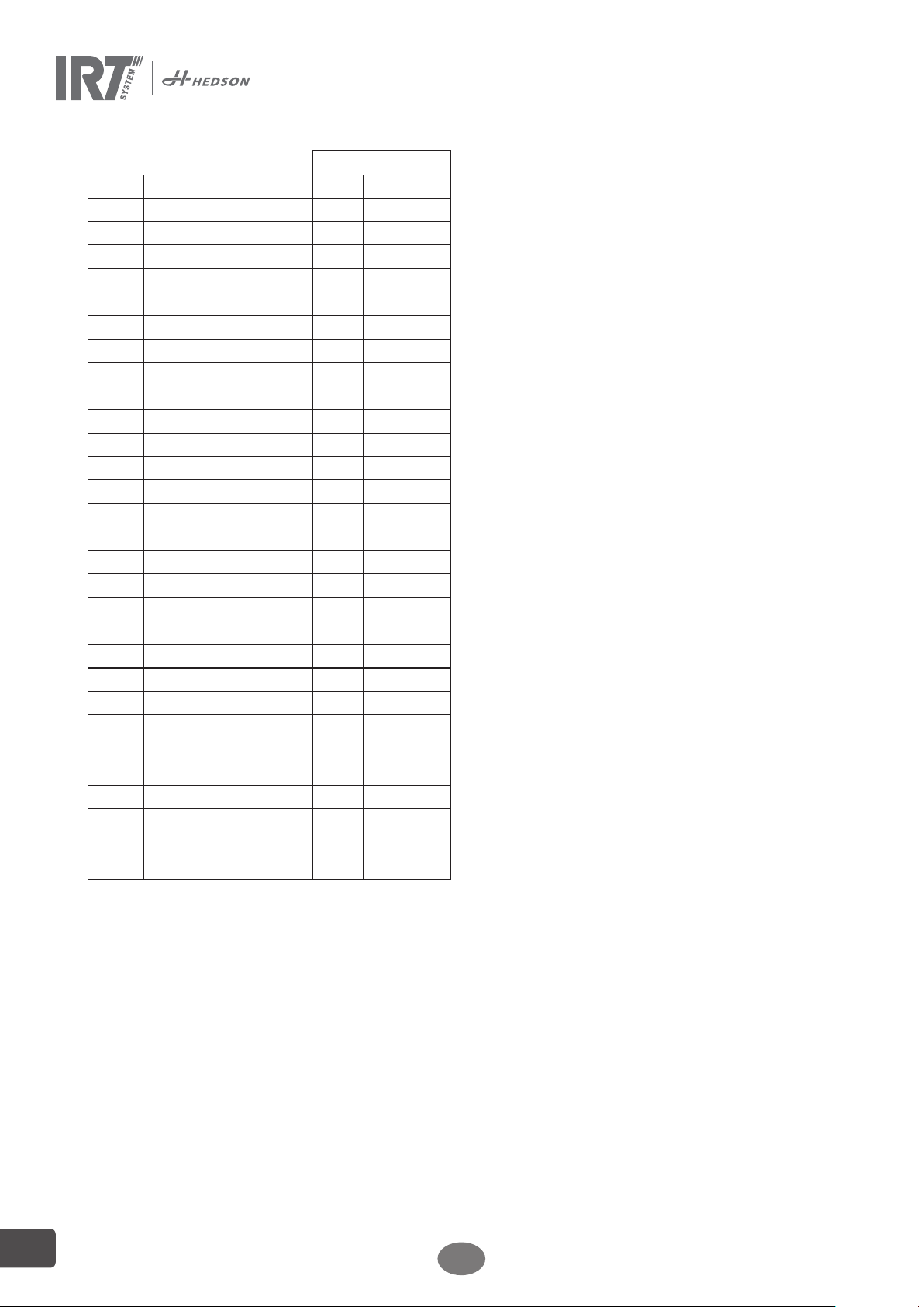
9.1 Log In
To enter the settings mode you first have to ”log in”. Press
both arrow keys as you turn the main switch on. The
display will ask you for a PIN code.
9.2 PIN code
Use the arrow keys to fill in the correct digit. Press enter
to confirm and edit the second, third, and fourth digit of
the code.
No code is required for basic settings, just press OK
for the default code of 0000. To change this code, read
chapter 9.4.6.
Advanced PIN co
Used for program adjustments and advanced settings. To
change this code, read chapter 9.4.14.
Attention! An entered PIN code is valid globally in the
software until the main switch is turned off, i.e. if you
enter advanced settings mode and then exit to program
mode. The program editing will still be editable until the
main power is turned off.
de 5780
9.3 Navigation
To adjust a setting, press edit. To go back from edit mode
to settings mode without saving, press cancel.
Note! If you press exit from settings mode you will be redirected to program mode. You will then need to repeat
from step 9.1 Log In to enter 9.4 Settings again.
Press exit
and you will
be directed
to “program
mode”.
Edit
mode
Use arrow keys to
change language and
select to confirm.
Use the arrow keys
to scroll through the
settings, see table in
chapter 8.4.
196349 rev 1
EN
9
Page 10
9.4 Settings
available in
Ch. Overview Basic Advanced
9.4.1 1 Select Language x
9.4.2 2 Power Mode x
9.4.3 3 Process Alarm x
9.4.4 4 Temp Unit x
9.4.5 5 Buzzer x x
9.4.6 7 Basic PIN Code x
9.4.7 8 Short Dist lim. x
9.4.8 9 Long Dist lim. x
9.4.9 15 Temperature Ctrl x
9.4.10 16 Disp. Contrast x x
9.4.11 23 Filter Time x
9.4.12 25 Demo Mode x
9.4.13 27 Dist Meas x
9.4.14 36 Advanced PIN Code x
9.4.15 37 Dist Unit x
9.4.16 43 Advanced Code x
9.4.17 44 Reset Prog. Settings x
9.4.18 45 Reset Filter Timer x
9.4.19 46 Statistics x x
9.4.20 47 Perform Self test x x
9.4.21 49 Power Rating 1 x
9.4.22 50 Power Rating 2 x
9.4.23 51 Power Rating 3 x
9.4.24 52 Puro Regulator P x
9.4.25 53 Pyro Regulator I x
9.4.26 54 Output 2 Scale x
9.4.27 55 Output 3 Scale x
9.4.28 56 Proc. Alarm temp. x
9.4.29 57 Continuous Mode x
9.4.1 1 Select Language
Use the up and down arrow keys to scroll through the
fourteen different languages (arranged alphabetically)
until the correct language appears. Press select to
confirm.
If you accidently switch to a language that you don´t
understand, turn the main switch on while pressing the
“cassette in use” button. The dryer will then start up with
British English.
9.4.2 2 Power Mode
The dryer is supplied from factory with "low" temperature settings for new users, which means that the preinstalled programmes are moderate set.
Note! The program settings that you changed/added
in program mode are only available in the low or high
program mode where thy were changed/added.
9.4.3 3 Process Alarm
Use the up and down arrow keys to set whether the
alarm is active or not. Press select to confirm.
9.4.4 4 Temp. Unit
°C and °F appear on the screen. Use the up and down
arrow keys to select the correct temperature unit. Press
select to confirm.
9.4.5 5 Buzzer
The sound effects can be muted/activated by using the
arrow keys to select no/yes. Press select to confirm.
9.4.6 7 Basic PIN Code
You can change the PIN code to prevent unauthorized access to the basic setting as described in table in
chapter 9.4. To do this, use the up and down arrow keys
to change the first digit, press select to confirm. Continue
with the second, third and fourth digit. When completed
press select to confirm the new four-digit PIN code.
9.4.7 8 Short Distance Limit (OPTION)
The original settings for the correct short distance limit
is 55 cm. You can change the value for the short distance
limit from 35 to 95 cm. Settings higher than 80 cm are
not recommended. Press select to confirm.
9.4.8 9 Long Distance Limit
The original settings for the correct long distance limit
is 65 cm. You can change the value for the long distance
limit from 40 to 130 cm. Settings higher than 100 cm are
not recommended. Press select to confirm.
9.4.9 15 Temperature Control (OPTION)
You can choose if you want to turn the temperature control (pyrometer) on or off permanently.
Note! If you turn the temperature control off in settings
mode you cannot activate it in program mode.
Temperature graphs and values will not be accessible
when this feature is turned off. Instead the software will
work with power levels, that is percentage of maximum
capacity.
9.4.10 16 Disp. Contrast
You can change the contrast of the display on a scale
from light to dark (25-75). Scroll between the values with
the up and down arrow keys and press select to confirm.
9.4.11 23 Filter Time
The default value is 400 working hours. After this time,
the filter replacement warning is displayed for filter
change. To deactivate the filter time, select 0hr. (from
version 5.SH.*).
If the dryer is placed in a dusty environment, it is recommended to change filters more frequently.
Note! Keep in mind that if the filter is too dirty, the lamp
service life will be reduced as a result of impaired cooling.
To reset, see 9.4.17.
9.4.12 25 Demo mode
The demo mode is for sales demo purposes.
9.4.13 Dist Meas
Enable or disable distance measuring for units with
distance sensor.
10
EN
196349 rev 1
Page 11
9.4.14 36 Advanced Pin code
To change the code to your personal choice, use the
up and down arrow keys to change the first digit, press
select to confirm. Continue with the second, third and
fourth digit. When completed press select to confirm the
new four-digit PIN code.
Warning! Make sure that you remember the new code.
9.4.15 37 Dist Unit
This provides you with the opportunity to change unit
type between centimeters and inches.
9.4.16 43 Advanced Code
It is possible to enable/disable the request for a PIN
code. This will remove the PIN code request in program
mode and the code 0000 will give you access to advanced settings. Press select to confirm your choice.
9.4.17 44 Reset Prog. settings
You can reset to the pre-programmed factory settings for
all programs. Confirm by pressing yes.
9.4.18 45 Reset Filter Timer
After a filter change on the cassette/s, restart the filter
timer with this setting. Confirm by pressing yes to reset
the filter time counting.
To adjust the value in the filter timer, see 9.4.11.
9.4.19 46 Statistics
The following information is available:
Run time
Shows accumulated working hours and minutes.
Start-ups
Shows the total number of starts of the dryer.
Σ (Total Power Consumption)
Presents the total energy consumption.
Φ (Average power consumption)
Presents the average consumption for all runs.
9.4.20 47 Perform Self test
In this test all the important input and outputs to and
from the computer can be tested. This test will give the
opportunity for a quick and accurate function verification
of the different parts of the system.
This test procedure is only available in English. By pressing the yes button, you enter the first step of the self-test.
To exit the self-test, press the start/stop button.
Automatic testing includes the following:
Test 1: Push Button Test
All buttons on the control unit are tested. The corresponding symbols are displayed by pressing the buttons.
Press enter for approx. three seconds in order to continue to the next step of the test program.
Test 2: Display Test
Verify that all pixels light up on the display. Press enter*
and check that all pixels go out. Press enter* to continue.
* or upper left software button
Test 3: Buzzer Test
Check that the buzzer sounds. Press enter or next to
continue.
Test 4: Cassette IR Test
The IR cassette lamps (output I) light up. Check that all
the IR lamps are lit. For safety reasons this test is limited
to 10 seconds. Press enter or next to continue.
Test 5: Ventilator Test/Cassette/Control unit
The ventilator in the cassette and control unit now starts.
A sound from the ventilator confirms that it is working.
If the dryer is equipped with two or more cassettes,
you will have to repeat test no. 4 and 5 for the other
cassette/-s. Press enter or next to continue.
Test 6: Laser Test (OPTION)
Direct the laser towards the object. Check that a red dotted circle or point is visible on the object. Press enter or
next to continue.
Test 7: Temperature Sensor Test (OPTION)
Direct the temperature sensor towards an object that is
at room temperature. The temperature on the display
should not deviate from room temperature by more than
±3 °C or ±5 °F. Press enter or next to continue.
Note! Temperature measurement is made as an average
of a surface according to chapter 8.1.
Test 8: Distance Sensor Test (OPTION)
Direct the distance sensor towards the object at a
distance of 0.3-1 m. Check that the distance shown on
the display matches the manually measured distance. A
deviation of ±3 cm is acceptable. Press enter or next to
continue.
Test 9: Cassette Temp. Switch and Circuit Board Temp.
The circuit board has a temperature measuring device
that is seen on the display. The temperature is shown in
ºC or ºF depending on the settings you have made. The
circuit board lifetime will be shortened if temperatures
are above 70ºC/158ºF during operation. If this happens
during drying a new window will appear after the completed drying cycle saying “warning High temp Pc”.
There is also an indication of the temperature in each
cassette which is in reality only a temperature switch
which will trigger when the temperature is above 150ºC.
The value -13ºC is given when the temp switch is not
triggered and - - - when it is triggered. If the temperature
gets too high during operation a warning will appear
showing the actual cassette and the value 500 the drying
operation will also be terminated.
Test Completed
Automatic testing is now complete. Press enter or next
to finish.
9.4.21 49 Power Rating 1
Possibilities to independently the other outputs give the
power rating for output 1.
Option: 0-99.9 kW where 0.0 is inactive.
9.4.22 50 Power Rating 2
Possibilities to independently the other outputs give the
power rating for output 2.
Option: 0-99.9 kW where 0.0 is inactive.
196349 rev 1
EN
11
Page 12
9.4.23 51 Power Rating 3
Possibilities to independently the other outputs give the
power rating for output 3.
Option: 0-99.9 kW where 0.0 is inactive.
9.4.24 52 Pyro Regulator P (Propotional)
This option, together with 9.4.25, is used to fine tune the
heating system depending on the pyrometer readings.
9.4.25 53 Pyro Regulator I (Integral)
This option, together with 9.4.24, is used to fine tune the
heating system depending on the pyrometer readings.
By tuning the two parameters P and I in the PID controller algorithm, the controller can provide control action
designed for specific process requirements. The response of the controller can be described in terms of the
responsiveness of the controller to an error, the degree
to which the controller overshoots the set point, and the
degree of system oscillation.
To alter the values for P and I full understanding of PID
controllers is needed.
If this knowledge is not at site, please contact Hedson
Technologies AB if this needs to be adjusted.
9.4.26 54 Output 2 Scale
Possibility to control the level of power on output 2 from
0-100% compared to output 1. Default is 100%
9.4.27 55 Output 3 Scale
Possibility to control the level of power on output 3 from
0-100% compared to output 1. Default is 100%
9.4.28 56 Proc. Alarm Temp.
Possibility to set maximum temperature difference between current and requested temperature (5-99ºC). This
function is activated in 9.4.3.
9.4.29 57 Continuous Mode
Possibility to decide if the IRT dryer should have continuous drying or time dependent drying. Yes = Continuous drying. No = Machine stops when time countdown
reaches 0.
10. Maintenance and Service
Maintenance work is to be carried out at the stipulated
maintenance intervals by suitably trained personnel.
Do not use running water or flammable liquids for cleaning.
Abide by the following points to ensure a long service
life and continuous operation of the dryer:
• Only original spare parts and suitable tools are to be
used.
• Adhere to the maintenance intervals.
• Contact your dealer or the manufacturer’s customer
service department regarding any maintenance
work that is not listed or shown in this manual.
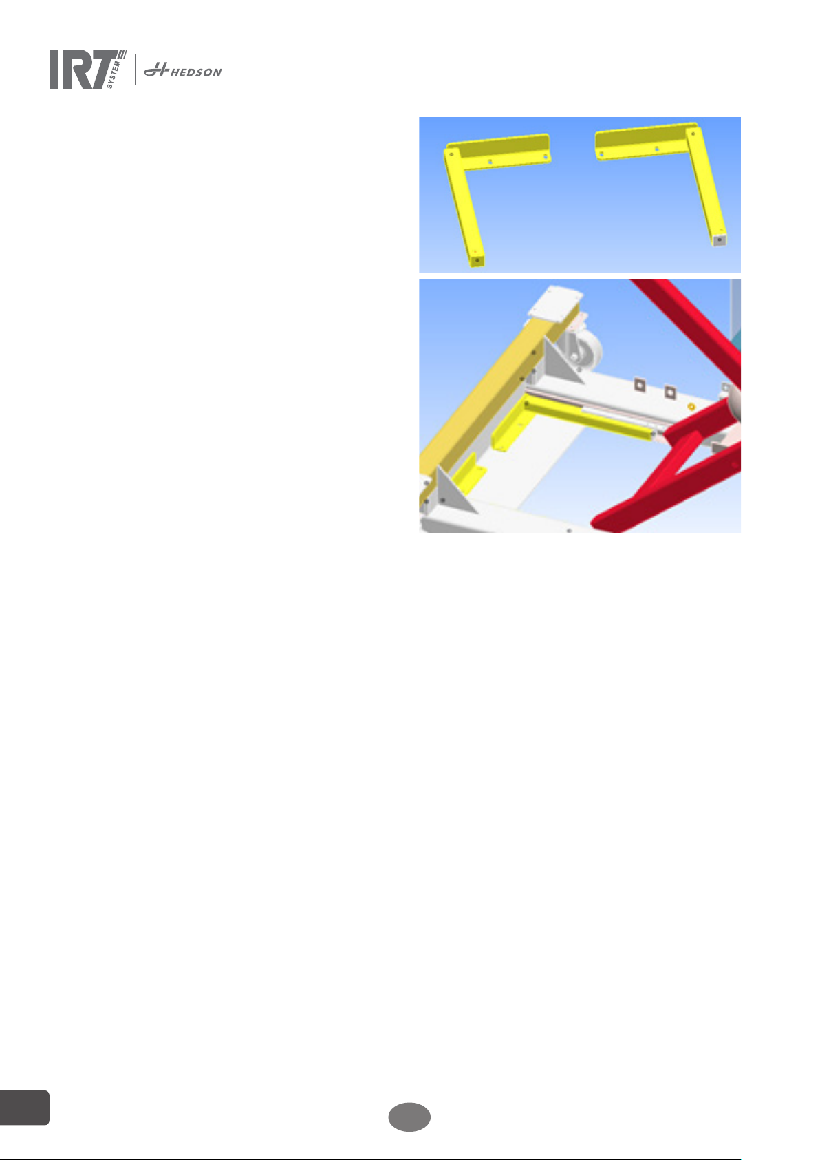
Only undertake maintenance work when the maximum
lift (unloaded) is reached, the platform table has been
reinforced by service supports (part no. 195682) or
secured by a forklift at the top position and the compressed air supply and electricity has been shut off.
10.1 Maintenance
Weekly
Check that all IR lamps light up during dryer operation.
Defect IR lamps can cause uneven heat distribution over
the surface.
Clean the dryer from dust, which can be a cause of fire,
with a damp cloth.
Check that all cables are undamaged. A damaged cable
can be a danger to life!
Monthly
Check the gold coated reflectors. Damaged or extremely
dirty reflectors can overheat the reflector body and/
or the cassette. In case of doubt, please contact the
customer service in order to clarify if the gold coated
reflector needs to be changed.
Check all moving parts such as pivot bolts, sliding pieces
and sliding surfaces for wear and tear; clean and lubricate. Only use greases in the lacquer coated sections
that do not contain substances that might damage the
lacquer coating.
Check air bellows and air hoses for damage. Inspect
visually and check for leaks. Check the surface of the air
bellows for contamination; clean and maintain. Always
use appropriate care and cleaning products when carrying out maintenance on the rubber surfaces.
Check that the valves are working correctly and check for
leaks.
Inspect the service unit provided by the customer (filter
regulator) and abide by the instructions in the manufacturer’s manual.
12
EN
196349 rev 1
Page 13
Yearly
Plan to change the air filter approx. once per year. You
will get a message in the software when it is time to
change. When starting up the dryer you will get an indication on how much of the filter time that is used.
Regular safety inspection. Inspection report, see 12.1.
Every 2 operating years
Replace the safety valve.
Every 6 operating years
Replace the complete set of air hoses.
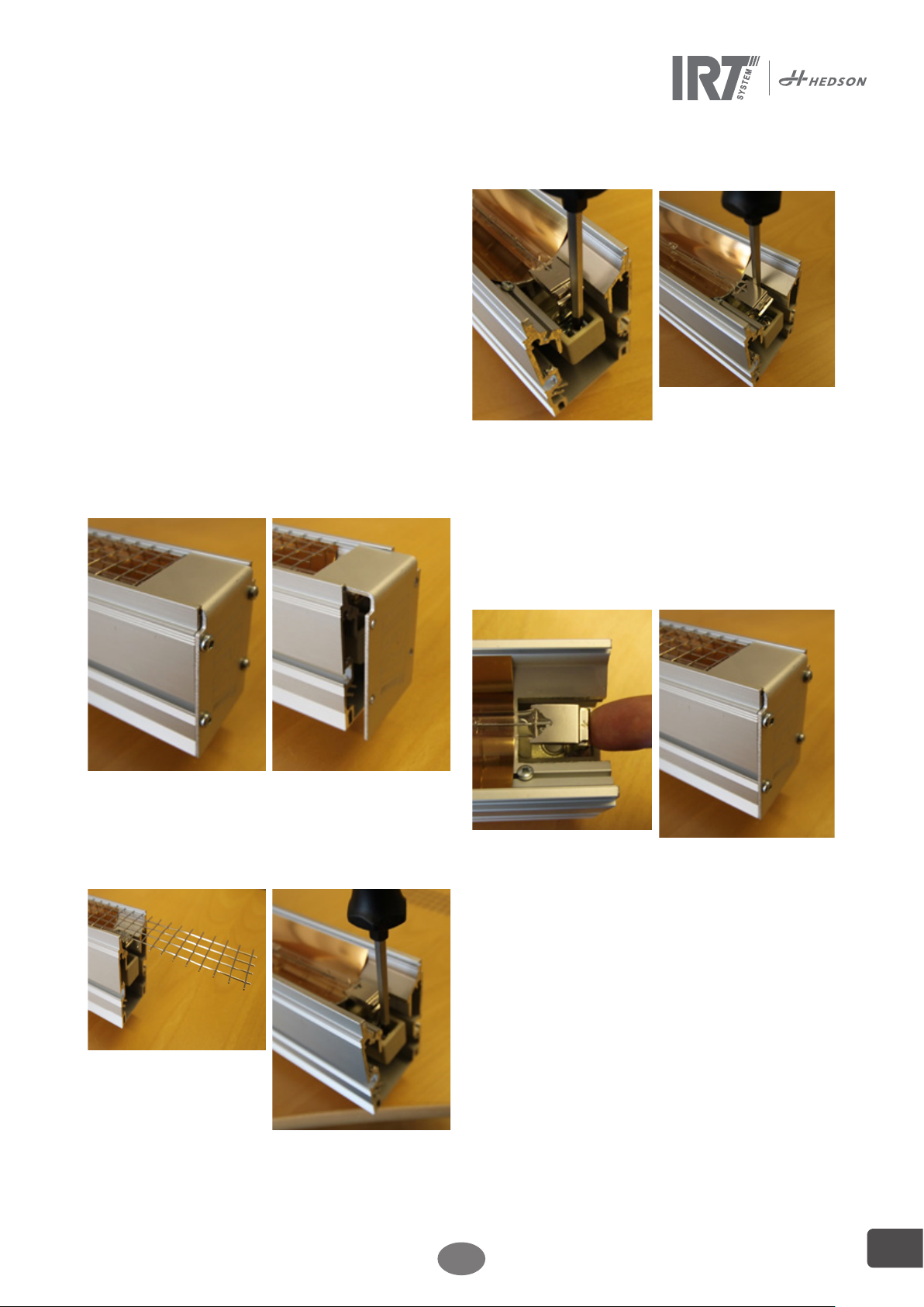
10.2 IRT lamp replacement
Note! Disconnect the cassette from the heaters mount-
ing frame of the dryer before service.
Attention!
Do not touch either the gold coated reflector or the new
IR lamp with your fingers. Only remove the protective
paper on the IR lamp after you have installed it.
Remove lamp
Attach lamp
Keep the protection paper around the lamp until the fitting is completed.
5. Fix the lamp in one of the
Lamp holders. Make sure
that the terminal strip
gets as far as possible
underneath the square
clamp. Fasten the screw.
Bend the other lamp end
with the finger and fix it
as the first one.
6. Focus the IRT-lamp by
centralizing it sideways
in the reflector body.
1. Loosen the mounting
screws on both end covers.
Pull the protection out of
3.
the slide. The screws for
the lamp holders will be
accessible
2. Loosen both lamp end
protections.
4.
Loosen the lamp end
screws and remove the
lamp.
7.
Focus the IRT-lamp by
centralizing it lengthways
in the reflector body
Remove the lamp protection paper.
8.
Push the protection
back into the slide and
attached the end covers.
10.3 Filter replacement
Attention!
The filters are disposable and should not be reused.
Use a knife or screw driver to open the filter box
1.
Remove the used filter.
2.
3. Insert the new filter.
4. Close the filter box.
.
196349 rev 1
EN
13
Page 14
10.4 Air bellows
The air bellow is a flexible element specially designed for
use in the lifting platform. The rubber cover is subject to
aging processes and must be checked carefully. Recorded data shows that a well-kept air bellows has a service
life of over 20 years.
Tips for a long service life:
• Use dry and oil-free compressed air.
• Protect from UV radiation (e.g. from welding or UV
dryers).
• Avoid the use of chemical products.
• Protect from mechanical damage (dents, etc.).
• Abide by the maintenance and care instructions, see
10.1.
Damaged air bellows must be replaced. Only original
parts from the manufacturer can be used
10.5 Comments on the filter regulator and air
supply lines
The filter regulator is not included in the Siemens Leading Edge Dryer package. A filter regulator must be installed in the air supply line (provided by the customer).
Use dehumidified, non-lubricated compressed air only.
Follow the instructions and recommendations provided
by the manufacturer of the filter regulator during maintenance and cleaning.
For other spare parts, please contact:
Hedson Technologies AB
Box 1530
462 28 Vänersborg
Sweden
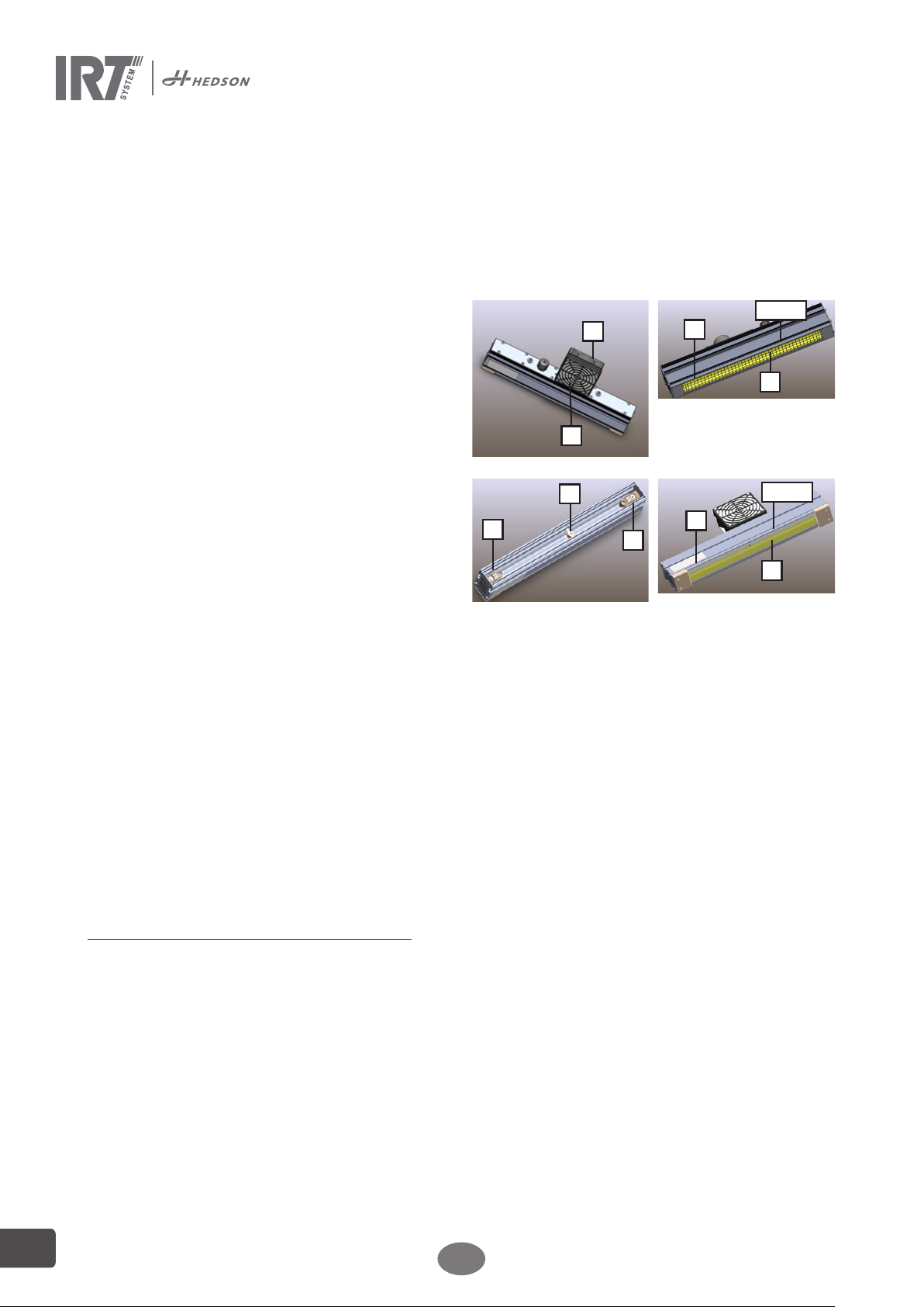
1
6
2
5
4
4
6
Net
3
Glass
3
10.6 Comments on the scissors' sliding areas
Due to the design principles, very strong forces are present on the sliding surfaces of the scissors. These forces
can lead to grooving in the sliding surfaces. They will not
affect the operation of the dryer.
The maintenance intervals described in 10.1 and other
manuals must be adhered to.
10.7 Disposal
Dispose of used items at the nearest environmental protection facility for recycling.
11. Spare parts
The following spare parts are the most common ones for
the SingleHeater IR-units.
Part Part nr.
1 Fan 202024
2 Filter 103055
3 IR lamp 790 mm 3 kW 102701
4 Lamp holder 109790
5 Temp switch 126043
Distance sensor 195266
Pyrometer 750231
6 Reflector E790 Gold foil 102696
6 Reflector E790 Net 193646
6 Reflector E790 Glass 716238
Printed Circuit Board (PCB) 750321
Solid State Relay (SSR) 750227
Display 750220
12. Safety Inspections
The safety inspection is required to ensure operational
safety of the dryer.
The following must be performed:
• Before commissioning the dryer at the manufacturer’s, use the Regular Safety Inspection form, see
12.1.
• After the initial commissioning, check at regular
intervals as per chapter 10. Use the Regular Safety
Inspection form, see 12.1.
• Enter the condition of the lifting platform in a separate copy of the inspection log and attach it to the
operating manual.
Note! The regular safety checks must be performed by a
suitably trained person. It is advisable to also implement
maintenance at the same time.
Note! After a replacement part has been attached during
service to the lifting equipment always perform a Regular
safety inspection
Contact Hedson Technologie's customer service department if you have any further questions.
E-mail [email protected]
14
Spare parts for Herkules working platform, see appendix
1: 761-054_PNTS-77
EN
196349 rev 1
Page 15
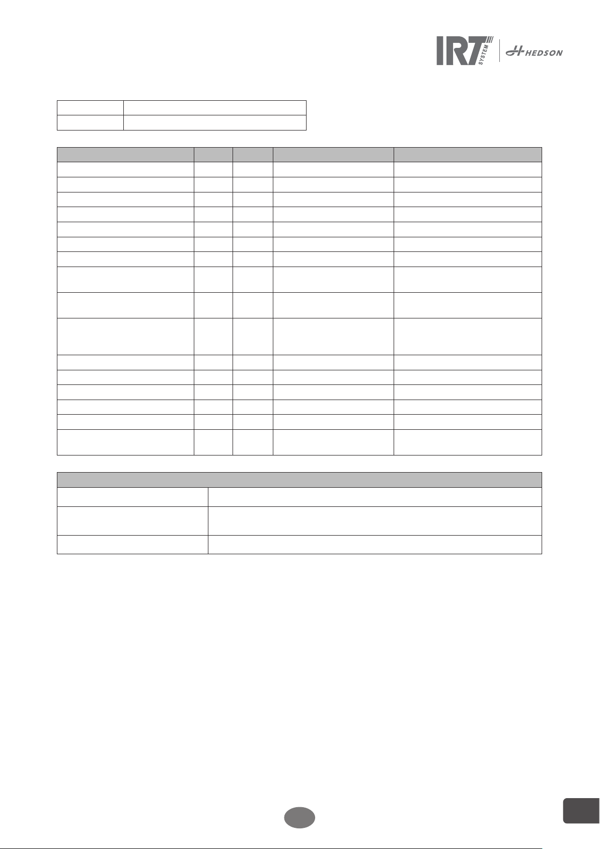
12.1 Regular safety inspection form
Device type
Serial No.
Inspection step OK Not OK Verification Remark
Name plate
Plate with load capacity
Plate with supply pressure
Lifting/lowering tag
All supporting screws are tight
Secure scissor pins
State of pneumatic hoses
Safety valve set to 6.5 bar
operating pressure
Mains pressure manometer
Pmax = 8 bar
Control lever automatically re-
sets to the zero position when
released
Fall arrester function
Emergency release status
Air bellows status
Supporting structure status
Function test – Lifting/lowering
Function test – Lifting/lowering
with load
Inspection result
Start-up not permitted, verification recquired.
Start-up possible, faults to be rectified by...................................................................
No fault, start-up possible immediately
Safety inspection performed on: .................................................................................................................................................
Name and address of qualified assessor: ...................................................................................................................................
.................................................................................................
Signature of qualified assessor
Fault rectification required
.................................................................................................
Signature of qualified assessor
.................................................................................................
Signature of assessor
.................................................................................................
Signature of operator
.................................................................................................
Signature of operator
.................................................................................................
Signature of operator
196349 rev 1
EN
15
Page 16
13. EC Declaration of conformity
According to testing institutes and according to the machinery directive the IRT products in this manual
are not defined as machines, wherefore the machinery directive reference cannot be included in this declaration.
In accordance with EN 17050-1:2010
We, Hedson Technologies AB
Box 1530
SE 462 28 Vänersborg
Sweden
declare under our sole responsibility that the product
IRT Siemens Leading Edge Protection Dryer
to which this declaration relates, is in conformity with the following standard(s) or other normative document(s):
EN 61000-6-4 Electromagnetic Compatibility, Generic Emission Standard.
EN 61000-6-3 Electromagnetic Compatibility, Generic Immunity Standard.
EN 60204-1 Safety of Machinery - Electrical equipment of machines.
EN ISO 9001 Quality Management System.
EN 292-1 Safety of Machinery.
EN 292-2 Safety of Machinery.
EN 1570-1:2011 Safety requirements for lifting tables.
in accordance with the provisions of the following directives in their most current version
2006/42/EC Machine Directiv
2006/95/EC Low Voltage Directive
2004/108/EC Electromagnetic Compatiblity Directive
2011/65/EU Directive on the restriction of the use of certain hazardous substances in
electrical and electronic equipment.
16
EN
196349 rev 1
Page 17
14. Pneumatic and Electrical diagrams
Pneumatic diagram for Hercules Working platform, see appendix 1: 761-054_PNTS-77
Electrical diagram for IRT Siemens Leading Edge Protection Dryer equipment is found in the appendix 2.
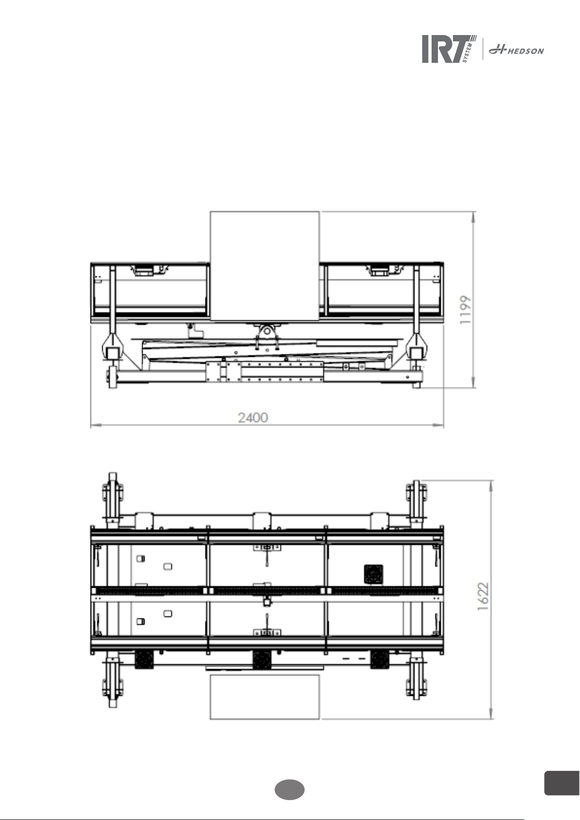
15. Weights and Dimensions
The overall weight is 665 kg
Dimensions as below:
For other technical specifications regarding Herkules working platform, see appendix 1: 761-054_PNTS-77.
196349 rev 1
EN
17
Page 18
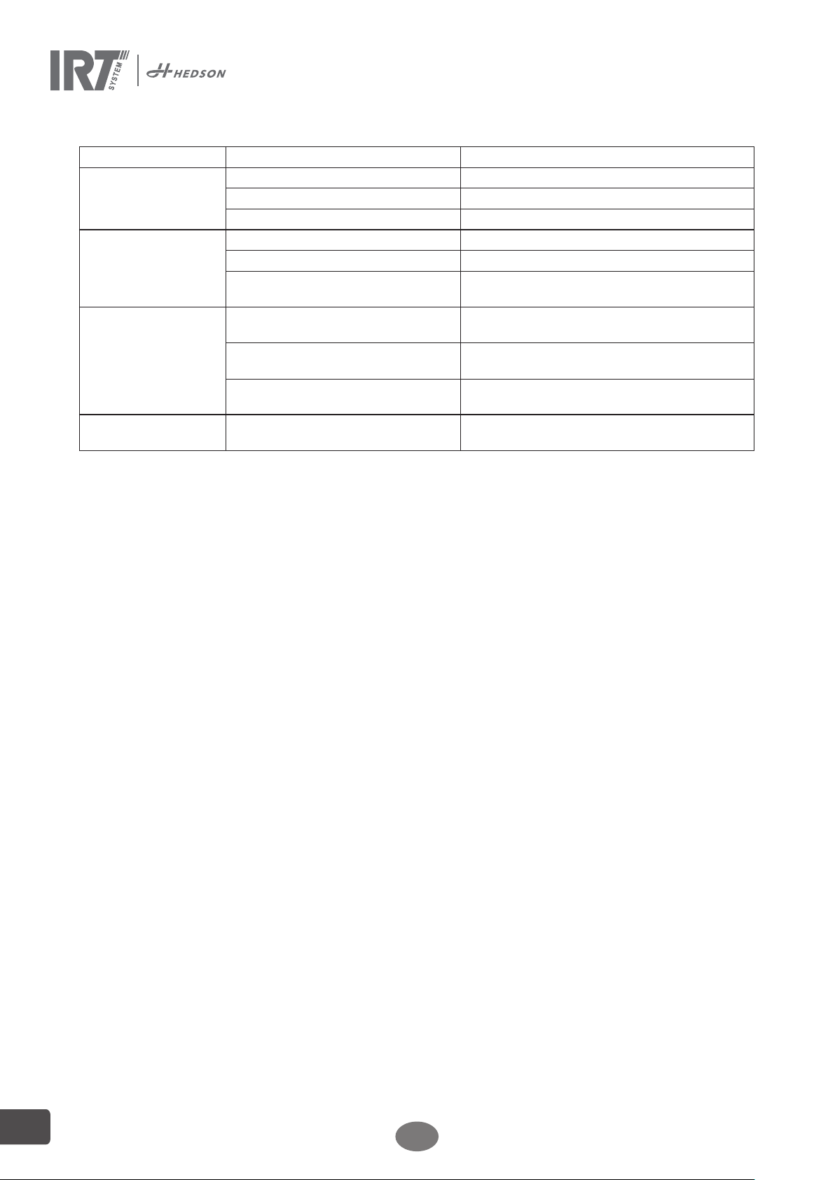
16. Trouble shooting
Malfunction Possible fault Rectification
Some lamps do not
light up
No lamps light up or
all lamps go out during
operation
Lifting malfunction Maintenance unit manometer without
Lowering malfunction Working platform is obstructed by an
Defective lamp Change lamp
One supply phase has failed Check fuses
Incorrect connection Check electrical connections in wiring diagram
Short circuit/damaged cable Check fuses. Change any defective components.
Incorrect connection Check electrical connections in wiring diagram
Temperature switch in cassette tripped Check fans, filters, hoses and ambient tempera-
ture. Reset by pressing the temp switch button.
Ensure the mains pressure is Pmax = 8 bar. Open
mains pressure
The hose lines are clamped, kinked or
damaged
Manometer pressure 1 bar above the
pressure permitted by the safety valve
obstacle
shut-off valve on control unit.
Check the hose lines and replace them with new
ones whenever necessary.
Check the safety valve for contamination and
replace it whenever necessary.
Lift the working platform, remove the obstacle,
and then lower the platform again.
18
EN
196349 rev 1
Page 19
70
196349 rev 1
Page 20
© Hedson Technologies 2017
The manufacturer reserves the right to introduce technical modifications.
HEDSON TECHNOLOGIES AB
Hammarvägen 4, 232 37 Arlöv
Tel +46 (0) 40 53 42 00
Telefax +46 (0) 40 43 29 01
www.hedson.com
HEDSON TECHNOLOGIES AB
Box 1530, SE-462 28 Vänersborg
Tel +46 (0) 40 53 42 00
Telefax +46 (0) 521 669 09
www.hedson.com
 Loading...