

Page 1
HEDMAN
OPERATING MANUAL
HF-400
FOLDER
Part Number 198569 HF REV. 12/04
®
The HEDMAN Company • 189 Gordon St. • Elk Grove Village, IL 60007 • 800-872-2788
Page 2

i
Rev. 12/04
HF-400
Operating Manual Contents
Introduction
Thank You ......................................................................................................................1
Description ......................................................................................................................1
Product Features ..............................................................................................................1
Controls And Indicators ..................................................................................................2
Customer Assistance ........................................................................................................6
Terminology ....................................................................................................................6
Important Safety Information..........................................................................................8
Set Up
Support............................................................................................................................9
Power ..............................................................................................................................9
Feed Table Extension ......................................................................................................9
Exit Conveyor................................................................................................................10
Stacker ..........................................................................................................................11
Document Preparation And Loading ............................................................................12
Standard Folds
General Set Up ..............................................................................................................14
Fold Length Settings......................................................................................................15
Length Adjustments ......................................................................................................16
Folding Sequences..........................................................................................................17
Skew Adjustments..........................................................................................................18
Custom Folds
General Set Up ..............................................................................................................19
Fold Measurements And Settings ..................................................................................19
Adjustments ..................................................................................................................19
Maintenance And Troubleshooting
Paper Jams ....................................................................................................................20
Cleaning ........................................................................................................................26
Tr oubleshooting ............................................................................................................28
Contents
Page 3

1
Rev. 12/04
HF-400
Operating Manual Introduction
Thank You
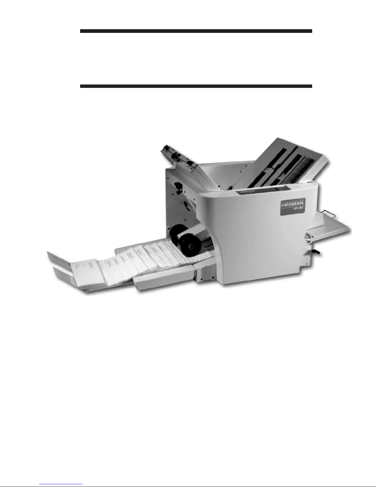
Thank you for purchasing the HEDMAN HF-400 document folder.
Properly used and maintained, this machine will provide many years of
reliable service.
Description
The HF-400 imparts both standard and custom folds to cut-sheet
documents from 3.25" x 5" (A6) up to 11" x 17" (A3).
Fold type and dimensions are set using the scales on the top tables
and documents to be folded are stacked between guides on the feed
table. The feed rolls take the top sheet from the stack and feed it into
the folding process. Finished documents exit the folding process and
are neatly stacked on the exit conveyor.
Product Features
The HF-400 incorporates advanced features for ease of operation,
office friendliness and reliability.
• Large, 400 sheet, document capacity.
• Top feed system takes a square stack of documents – no fanning
needed.
• Fold tables are arranged in a “V” pattern for easy operator access
and visibility.
• Quick, flip-slide-snap macro adjustments for paper stops in the
center of the fold tables.
• Convenient micro adjustment knobs for paper stops at the top ends
of the fold tables.
• Easy paper thickness and skew adjustments.
• Out-feed stacking rollers at the exit conveyor self-set for standard
folds. They can also be adjusted for custom folds.
• Powered exit conveyor provides neat stacking.
• Extended exit tray accumulates a large output.
• Insulated for noise reduction.
• Heavy gauge steel chassis for an extremely strong machine assuring
perfect alignment.
• Split style fold tables allow easy maintenance by removal of only the
top portion of the tables – easy, light and free of power connections.
• Removable top roller for easy access and cleaning.
Page 4
2
Rev. 12/04
HF-400
Introduction Operating Manual
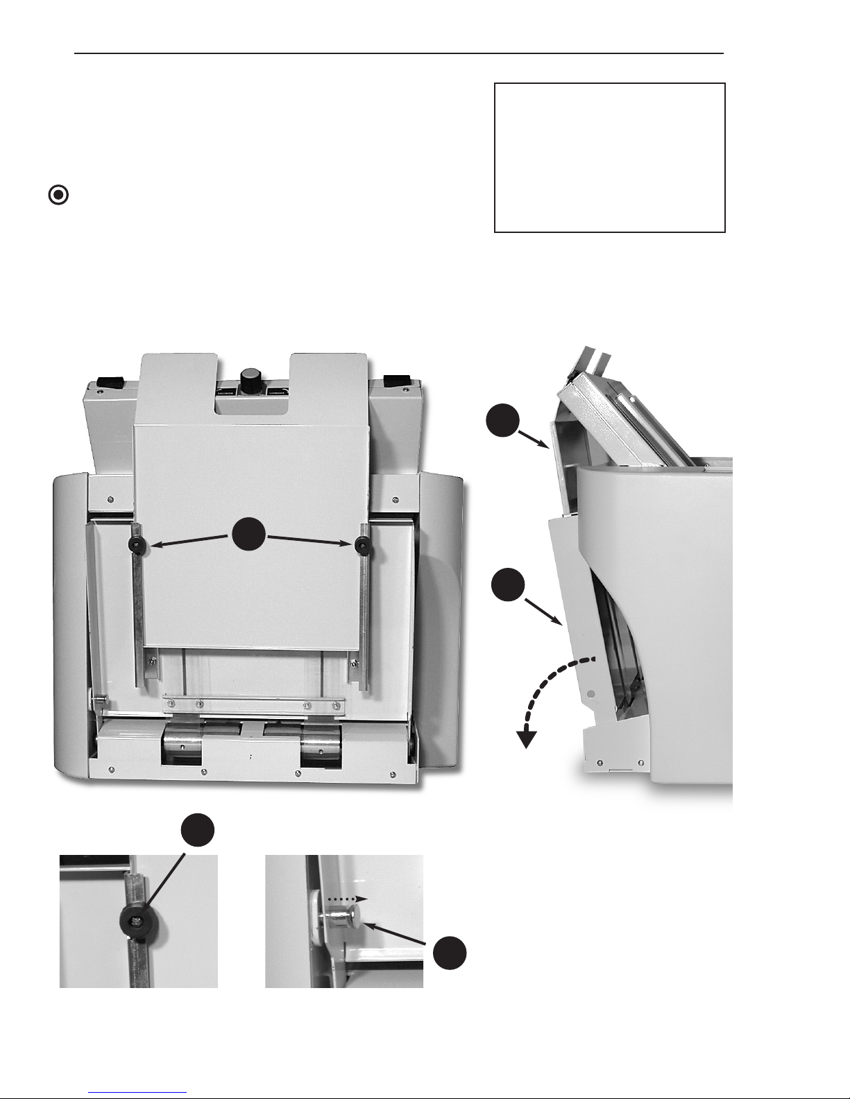
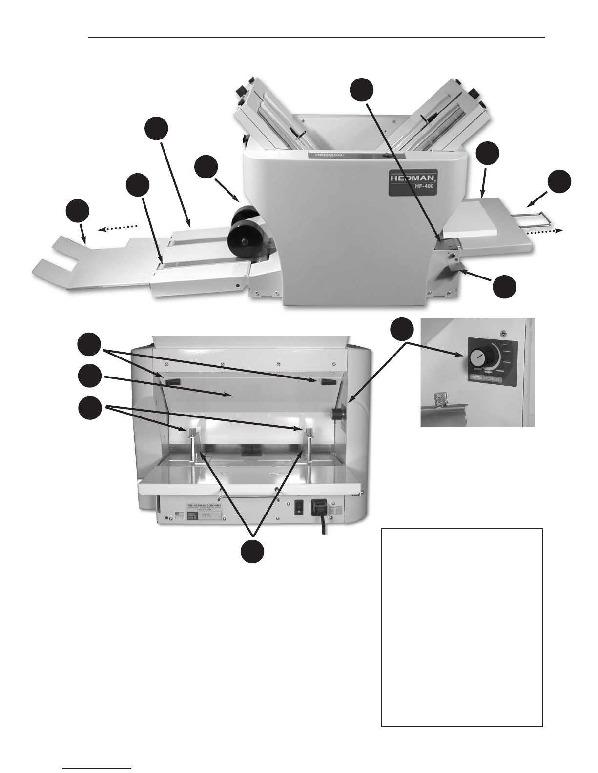
1. Exit Tray Retaining Screw
(No. 2 Phillips)
2. Exit Conveyor Foot
3. Exit Conveyor Latch
(pull to release)
4. Exit Conveyor (folds down)
5. Exit Tray
Controls and Indicators
This page and the next page show the HF-400
with the feed and exit devices folded to conserve
table space when the machine is not in use.
NOTE
The stacker assembly must be removed (see page
11) in order to fold up the exit conveyor and tray.
See pages 4 and 5 for additional controls and indicators.
1
2
3
4
5
Page 5
3
Rev. 12/04
HF-400
Operating Manual Introduction
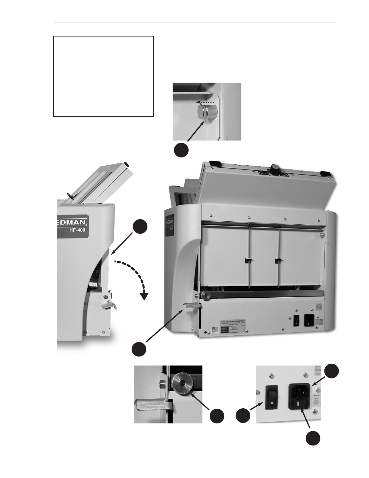
6. Feed Table Extension (folds
down)
7. Feed Table Extension Latch
(pull to release)
8. Skew Adjustment Knob
9. Power Cord Socket
10. Fuse Drawer
11. Main Power Switch
33. Feed Table Lever
6
7
9
10
11
8
33
Page 6
4
Rev. 12/04
HF-400
Introduction Operating Manual
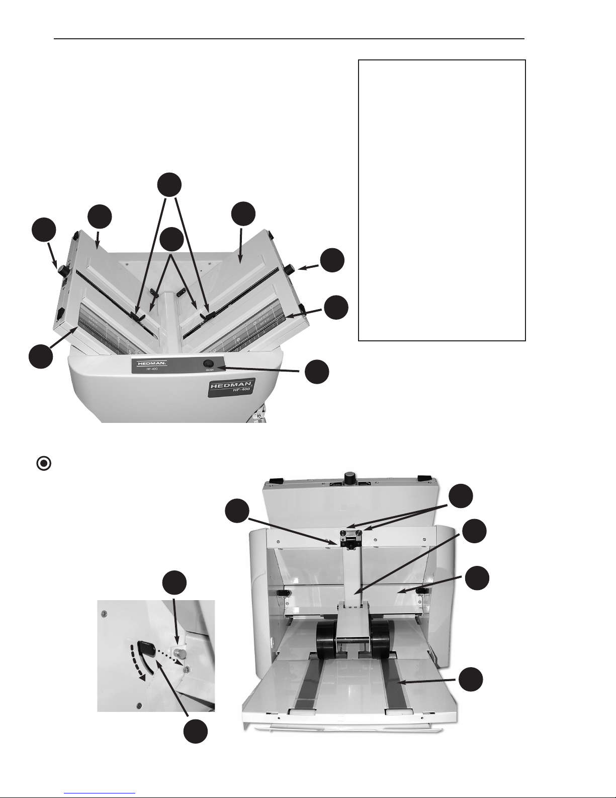
12. Fold Table (first fold)
13. Fold Table (second fold)
14. Fold Stop Lever
15. Fold Stop Latch
16. Fold Length Fine
Adjustment Knob
17. Fold Table Scales
18. Folder Start/Stop Switch
19. Stacker Assembly Center
Knob (adjustment)
20. Stacker Assembly Thumb
Screw (attachment)
21. Stacker Assembly
22. Exit Conveyor Belt
23. Exit Area Access Door
24. Exit Area Door Latch
(pull to release)
25. Top Roller Release Lever
(rotate down to release
roller)
Controls and Indicators
This page and the next page show the HF-400
with all its elements in their operating positions.
See pages 2 and 3 for additional controls and
indicators.
NOTE
See page 11 for additional
stacker assembly detail.
23
24
12
13
18
19
14
15
20
21
16
16
17
17
22
25
Page 7
5
Rev. 12/04
HF-400
Operating Manual Introduction
33
34
23
5
6
32
4
31
26
30
27
28
29
4. Exit Conveyor
5. Exit Tray
6. Feed Table Extension
26. Paper Guides
27. Paper Guide Lock Knobs
28. Paper Thickness
Adjustment Knob
29. Feed Area Access Panel
30. Feed Area Access Panel
Latch
31. Feed Table
32. Long Paper Support
33. Feed Table Lever
34. Stacker Assembly Roller
Page 8

6
Rev. 12/04
HF-400
Introduction Operating Manual
Customer Assistance
Should you encounter any problems with this machine or not
understand its many features, please refer to this manual.
If you require further assistance after reading this manual,
please contact the authorized Hedman Dealer or Distributor
for your location. These authorized Hedman Representatives
employ factory trained service technicians and stock genuine
Hedman spare parts.
To find the authorized Hedman Dealer or Distributor for your
area, call 847-718-6500 or visit our Web site www.hedmanco.com.
Terminology
Several terms have specific meanings as they are used in this manual:
DOUBLE-PARALLEL FOLD
A fold that divides the sheet into four panels. Useful for inserting
legal size sheets into business envelopes. This fold cannot be
made in sheets smaller than legal size.
EXIT END
The left end of the HF-400 where the folded documents exit the
machine.
FEED END
The right end of the HF-400 where the flat documents are placed
to enter the folding process.
FOLD TABLE
The sloping portion of the HF-400 that controls the position of
the fold on the document. The first fold is formed when the document is in the fold table to the right; the second fold is formed
when the document is in the fold table to the left.
GATE FOLD
A fold that divides the sheet into one panel that is half the length
of the sheet and two overlapping panels one quarter the length of
the sheet.
Page 9

HF-400
Operating Manual Introduction
7
Rev. 12/04
Terminology
LEADING EDGE
The edge of the document that enters the folding process first.
LETTER FOLD
A fold that divides the sheet into three panels with the front of
the top and bottom parts of the sheet facing in. (Sometimes
called a “C” fold.)
OPERATOR SIDE
The side of the HF-400 that is nearest the operator. Operating
controls can be conveniently reached from this side. No controls
are on the opposite side.
SINGLE FOLD
A fold that divides the sheet into two panels. This is the first fold
in the sheet and there is not a second fold.
STANDARD FOLD
Any of the five folds for which icons are shown on the fold table
scales when made in standard (8.5" x 11", 8.5" x 14" & 11" x
17") size sheets. Those five folds become custom folds when
made in other sheet sizes as do variations of the five folds in any
size sheet.
TRAILING EDGE
The edge at the last part of the document to be drawn into the
machine.
ZIG-ZAG FOLD
A fold that divides the sheet into three panels with the front of the
top part of the sheet facing out and the front of the bottom part
of the sheet facing in. This fold is often used to allow the address
to show through a window envelope. (Sometimes called a “Z” fold
or accordion fold.)
Page 10

8
Rev. 12/04
HF-400
Introduction Operating Manual
Important Safety Information
To make the most of the HF-400, it must be operated and maintained
properly. Please read these operating and maintenance instructions carefully before using the HF-400.
Special attention must be paid to the
WARNING and
CAUTION statements in this manual.
WARNING
Statements identify conditions that could result in personal injury or
loss of life.
CAUTION
Statements identify conditions that could cause damage to equipment
or documents being folded.
NOTE
Statements identify conditions that do not warrant a warning or caution,
but are unusual or may not be unexpected. They are also used to point
out available alternatives or to add emphasis to important points.
Before operating or maintaining the HF-400, please read these general warnings and cautions.
WARNINGS
NEVER clean, clear or disassemble the HF-400 without first unplug-
ging the power cord.
ALWAYS keep loose clothing, ties, scarfs, and hair away from all mov-
ing parts.
NEVER place fingers between or near moving parts.
CAUTIONS
DO NOT disassemble the HF-400 further than removing access panels
and fold tables as shown in this manual. There are no user serviceable
parts in the unexposed areas.
NEVER allow liquids to splash or spray into the HF-400.
ALWAYS stop the feeding of documents at the first indication of jams
or improper folds.
TRY OUT new folds on blank paper before loading documents that
cannot be readily replaced.
Page 11
9
Rev. 12/04
HF-400
Operating Manual Set Up
Support
Place the HF-400 on a solid table or stand in a
position where the operator has access to both
ends of the machine as well as to the operator
side of the machine.
WARNING
Always use two people to lift and position the
machine. In addition to its weight, the size of
the HF-400 can place a single person in an
awkward or unbalanced position.
Adequate space should be provided near the
machine for flat and folded documents.
Power
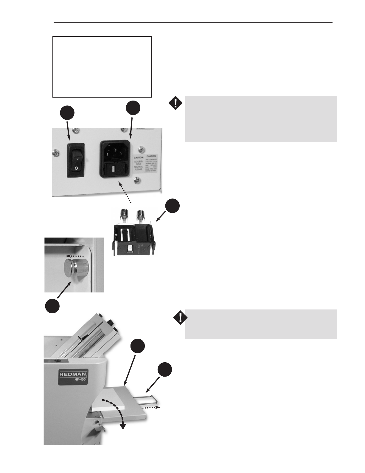
Connect the HF-400 to a 120V power outlet
with the supplied cord. The cord plugs into the
socket (9) at the bottom right corner of the feed
end of the machine.
After set up is complete, the main power switch
(11) can be turned on to activate the machine.
The fuse drawer (10) contains two
T3.15AL250V fuses, one in the hot line and
one in the neutral. Both fuses must be in place
for the HF-400 to operate.
WARNING
Unplug the power cord before removing the
fuse drawer.
Feed Table Extension
If the feed table extension (6) has been folded
up, pull the feed table extension latch (7) and
lower the extension to the operating position.
For sheets longer than 14”, pull out the long
paper support (32) to support the trailing edge
of the documents.
9
10
11
32
6
7
6. Feed Table Extension
7. Feed Table Extension Latch
(pull to release)
9. Power Cord Socket
10. Fuse Drawer
11. Main Power Switch
32. Long Paper Support
Page 12
10
Rev. 12/04
HF-400
Set Up Operating Manual
5
4
Exit Conveyor
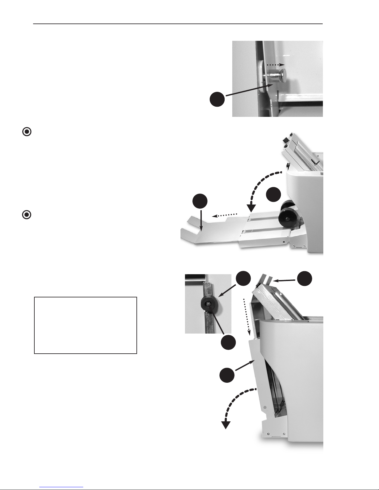
If the exit conveyor (4) has been folded
up, pull the exit conveyor latch (3) and
lower the exit conveyor to the operating
position.
The exit tray (5) can be extended if more
than a few documents are to be folded in
a batch.
NOTE
After lowering the exit conveyor, re-attach
the stacker assembly (see page 11).
NOTE
If the exit tray (5) has not been assembled
to the exit conveyor (4), slide the exit tray
into the guides in the underside of the exit
conveyor and assemble the exit tray retaining screw (1) with the exit conveyor foot
(2) into the pre-drilled holes in the guides.
3
5
4
1
2
1. Exit Tray Retaining Screw
2. Exit Conveyor Foot
3. Exit Conveyor Latch
(pull to release)
4. Exit Conveyor
5. Exit Tray
Page 13
11
Rev. 12/04
HF-400
Operating Manual Set Up
20
20
19
21
35
36
37
Ready to Attach
Attached
Stacker
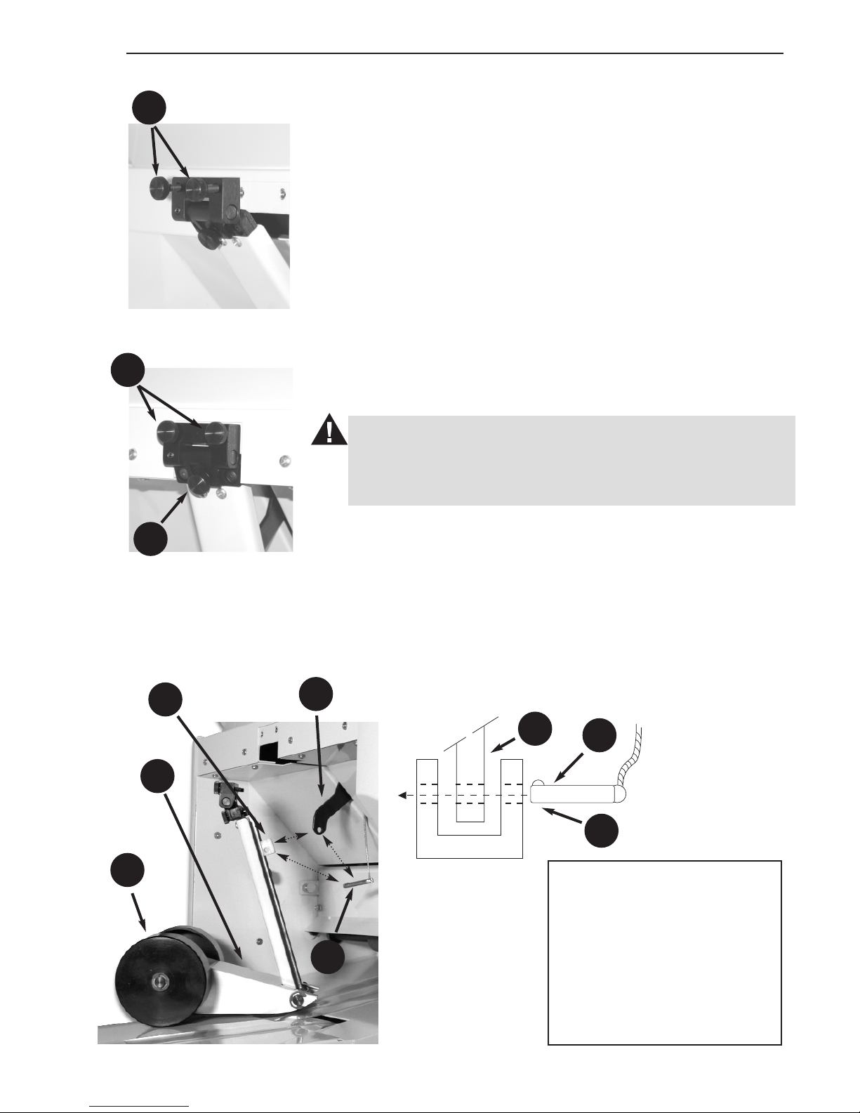
To attach the stacker assembly (21) to the machine, position it
above the exit conveyor and fasten it with the stacker assembly
thumb screws (20) as shown in the two illustrations at left.
After the stacker assembly is attached to the machine:
FOR STANDARD FOLDS:
1. Move the fold stop lever extension (36) to about the midpoint of the table.
2. Engage the extension with the stacker connection slider
(35) and insert the snap pin (37). The stop lever extension
fits into the slot in the stacker connection slider and their
holes must be aligned to insert the snap pin as shown in
the detail illustration.
3. Allow the stacker to self-adjust its position to each fold.
CAUTION
The stacker assembly center knob (19) must be loose (turned
fully counter-clockwise) when the stacker is connected to the
stop lever extension.
FOR CUSTOM FOLDS:
1. Pull the snap pin (37) to disconnect the stacker assembly
from the stop lever extension.
2. Place a sample of the custom folded sheet at the machine
exit.
3. Manually position the stacker assembly rollers (34) about
1” from the folded sheet.
4. Tighten (clockwise) the stacker assembly center knob (19)
to keep the stacker in position.
19. Stacker Assembly Center
Knob (adjustment)
20. Stacker Assembly Thumb
Screw (attachment)
21. Stacker Assembly
34. Stacker Assembly Roller
35. Stacker Connection Slider
36. Fold Stop Lever Extension
37. Snap Pin
36
37
35
34
Page 14
12
Rev. 12/04
HF-400
Set Up Operating Manual
33
Document Preparation
And Loading
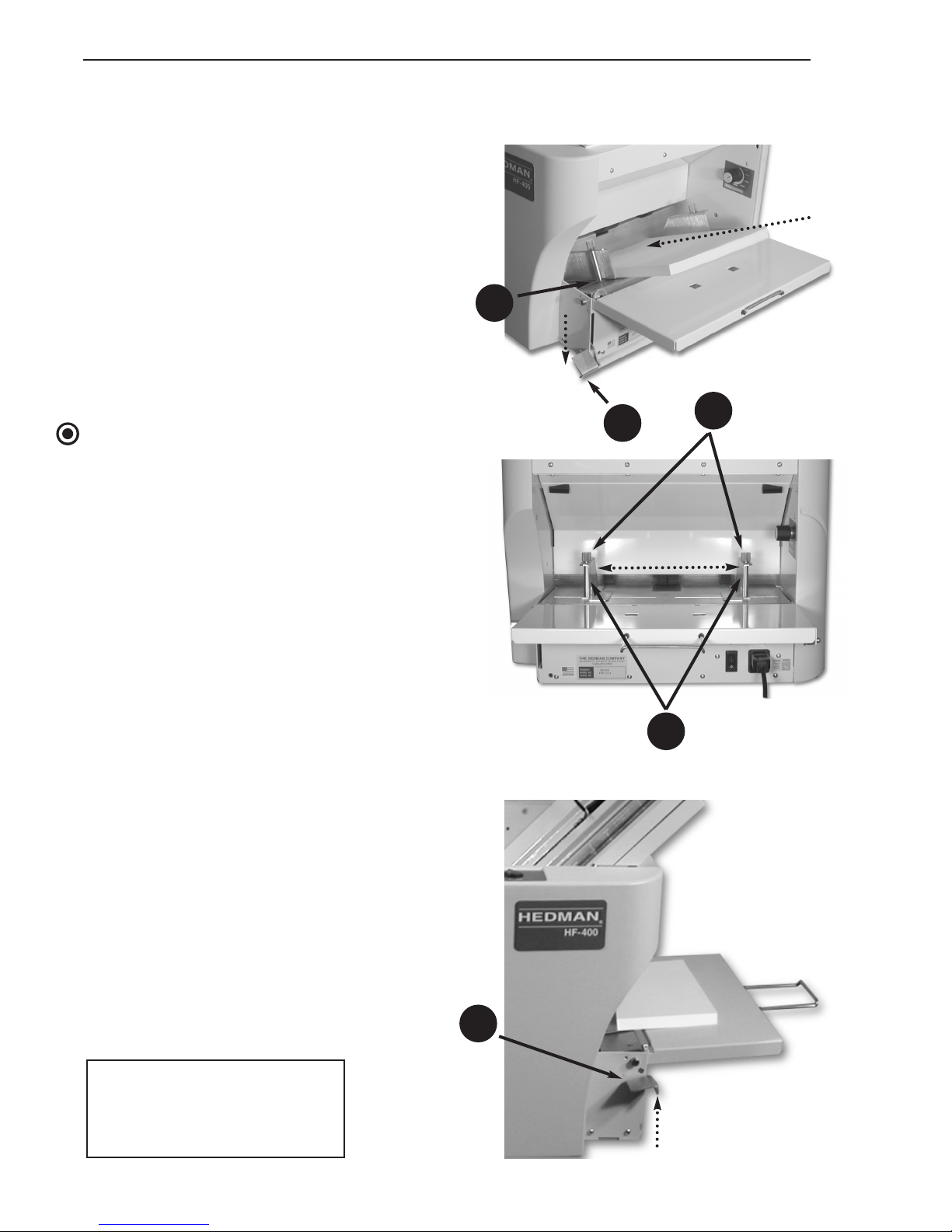
The stack of documents to be loaded should
be squared up as much as possible — to look
similar to the stack that comes out when a
new ream of paper is unwrapped.
To load the document stack:
1. Depress the feed table lever (33) to lower
the leading edge of the feed table (31).
2. Insert the document stack all the way into
the machine until it rests firmly against the
stop.
NOTE
The documents should be inserted with the
printed or front side up.
3. Move the self-aligning paper guides (26)
inward until they are just snug against the
document stack.
4. Tighten the paper guide lock knobs (27) on
both guides to keep them snug against the
stack.
5. After the guides have been locked, return
the feed table to its level position by raising
the feed table lever (33).
The stack will be captured between the feed
table at the bottom and the feed rollers at
the top.
26
27
33
RAISE
DEPRESS
ADJUST
INSERT
31
26. Paper Guides
27. Paper Guide Lock Knobs
31. Feed Table
33. Feed Table Lever
Page 15
13
Rev. 12/04
HF-400
Operating Manual Set Up
Document Preparation
And Loading
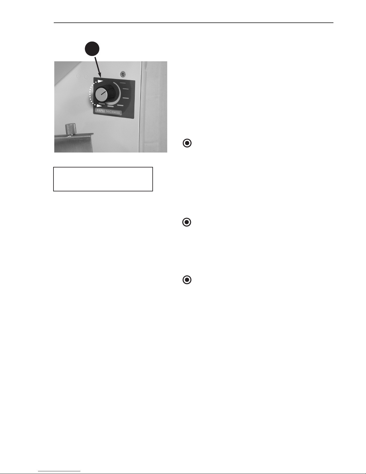
After raising the feed table, adjust the paper
thickness adjustment knob (28) to match the
stock on which the documents are printed.
The knob has six detented positions to adjust
for paper from thin to thick. The knob is
shown at the second tick mark for 20 pound
paper. As paper thickness increases, rotate the
knob clockwise.
NOTE
Paper feed characteristics vary depending on
humidity, paper surface, type of ink used to
print the document, and other factors.
Therefore, settings for one document of a given
thickness may not be the same as those for
another document of the same thickness. A certain amount of trial and error may be necessary
with this adjustment.
NOTE
Heated processes such as in copiers and laser
printers can cause paper to curl. Be sure the
documents are flat before loading them into
the HF-400. If necessary, reverse curl the documents to flatten them.
NOTE
It may be possible to fold thicker sheets or specially finished paper on the HF-400. If these
will not run with the available range of user settings, contact the local authorized Hedman
Dealer or Distributor for assistance.
28
28. Paper Thickness
Adjustment Knob
Page 16
14
Rev. 12/04
HF-400
Standard Folds Operating Manual
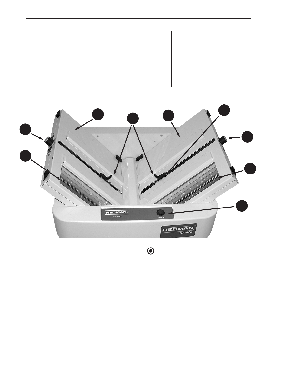
To set up the HF-400:
1. Make initial length settings for the first and
second folds using the scales (17) and indicators (38) (see page 15).
2. Load a few sheets of blank paper between the
paper guides on the feed table (see page 12).
3. Press the Start/Stop switch (18) to fold two
or three sheets.
4. Check that the fold is as desired.
5. Make fine adjustments in the fold length (see
page 16) and skew (see page 18). Test until
the fold is as desired.
6. Remove trial material, load the document
stack and turn on the switch.
12. Fold Table (first fold)
13. Fold Table (second fold)
14. Fold Stop Lever
15. Fold Stop Latch
16. Fold Length Fine
Adjustment Knob
17. Fold Table Scales
18. Folder Start/Stop Switch
Standard Folds
The scales on the HF-400 fold tables contain symbols for the five most popular folds
and colored bands for the three most popular paper sizes. This makes it easy to adjust
the machine for these folds.
Only the simple controls at the top of the
HF-400 are needed to set up the machine.
NOTE
Before changing fold settings or making fine adjustments, be sure the folding area of the HF-400 is cleared of all
sheets. Either:
• Let the feed area run out of paper.
• Press thumb or finger lightly on top
of the stack on the feed table while
the machine is running. (See illustration at the top of page 15.) Feeding
will stop and the machine will clear
itself. This allows repeated trials
without reloading paper each time.
12
13
18
14
15
16
16
17
17
Page 17
15
Rev. 12/04
HF-400
Operating Manual Standard Folds
Fold Length Settings
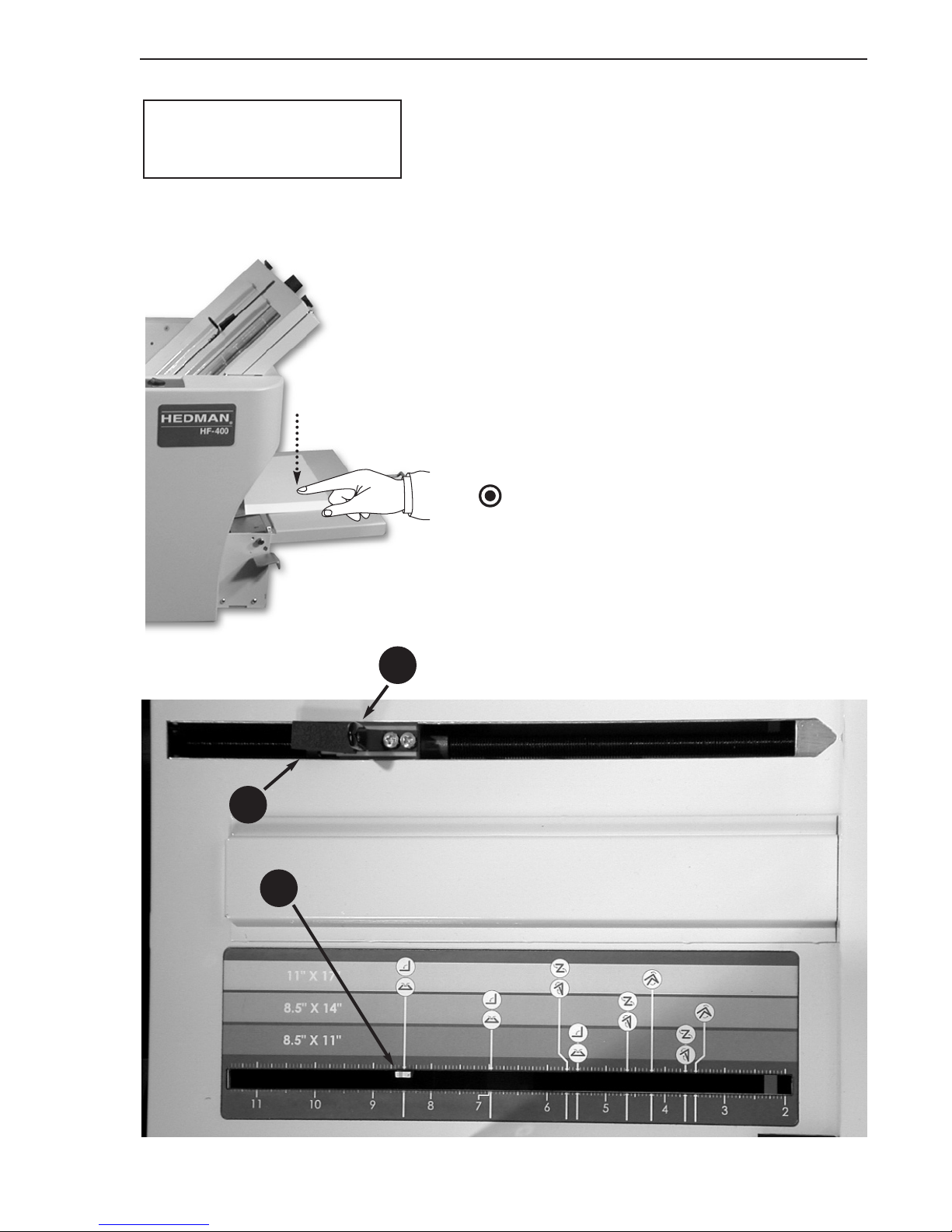
The scales (17) on the fold tables are as shown
(second fold scale illustrated) with bands of:
• Light blue for 11" x 17"
• Medium blue for 8.5" x 14" (legal size)
• Dark blue for 8.5" x 11" (letter size).
Fold symbols on the colored bands have
leader lines to show where the indicator (38)
should be positioned for that fold. The illustrated example shows the indicator position
for the second fold in an 11" x 17" sheet for
either a single fold or a gate fold. The setting
for the first fold will determine which of the
two will result from this second fold.
NOTE
The indicator may be slightly off center after
adjustment to get a perfect fold. Different
paper types and weights will have slightly different positions on the paper stop indicator.
14. Fold Stop Lever
15. Fold Stop Latch
38. Fold Length Indicator
15
38
PRESS
14
Page 18
16
Rev. 12/04
HF-400
Standard Folds Operating Manual
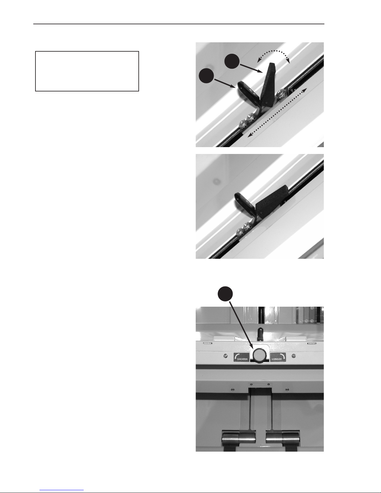
To move the indicator to the desired fold position, rotate the latch (15) up to the stop lever
(14) and slide the stop lever up or down the
table. The indicator will move with it.
Rotate the latch down to lock the lever and
indicator in place.
Length Adjustments
Fine adjustment of the fold length is accomplished with the fine adjustment knob (16).
When adjusting fold length with this control,
at least one full rotation of the knob will be
required to make a noticeable change.
To make fine adjustments in the fold length:
1. Evaluate whether the first fold needs to be
nearer to the leading edge of the sheet or
further away from it. Then, evaluate
whether the second fold needs to be nearer
to the first fold or further away from it. (See
page 17 for fold sequences.)
2. Turn the fine adjustment knob (16) in the
shorten direction if the first fold needs to
be nearer the leading edge. Turn it in the
lengthen direction to move the fold further
down from the leading edge. Make corresponding adjustments for the second fold if
needed.
Latch Down–Adjustment Locked
14
15
16
14. Fold Stop Lever
15. Fold Stop Latch
16. Fold Length Fine
Adjustment Knob
Fold Settings
Page 19
17
Rev. 12/04
HF-400
Operating Manual Standard Folds
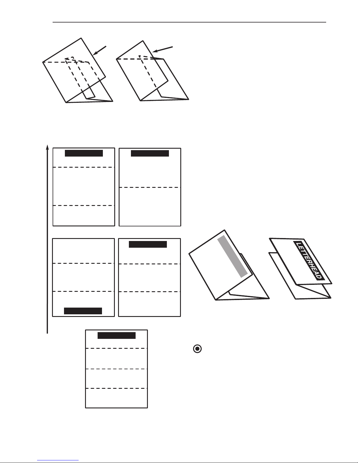
Length Adjustments
Example:
Two imperfect letter folds and their corrections demonstrate examples of using
the fine adjustment knob.
Folding Sequences
The following illustrations of the five
preset folds can be used to evaluate the
finished product. All measurements are
from the leading edge of the sheet.
NOTE
When fed into the HF-400 as shown to the
left, the letter and zig-zag folds will position
the letterhead and address properly as
shown.
Corrective action:
• Shorten first fold
• Lengthen second fold
Corrective action:
• Lengthen first fold
• Shorten second fold
Trailing Edge
Trailing Edge
Zig- Zag Fold
Address Outside
LETTERHEAD
Letter Fold
Address Inside
Feed Direction
Gate Fold
LETTERHEAD
First Fold
Second Fold
Single Fold
LETTERHEAD
First Fold
Second Fold
Letter Fold
First Fold
Double Parallel Fold
LETTERHEAD
LETTERHEAD
Second Fold
First Fold
Second Fold
Zig-Zag Fold
LETTERHEAD
Second Fold
First Fold
Page 20
18
Rev. 12/04
HF-400
Standard Folds Operating Manual
Skew Adjustments
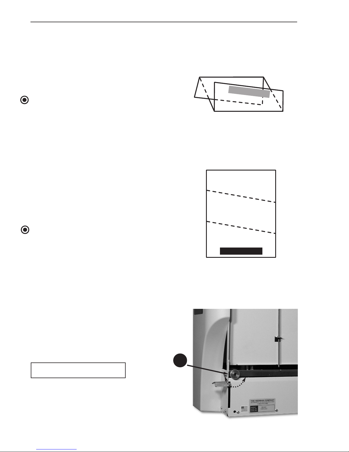
Folds that are not perfectly parallel to the
leading and trailing edges of the sheet can be
corrected with the skew adjustment knob (8).
NOTE
Before making any skew adjustments, be sure
the paper thickness adjustment (see page 13)
is properly set for the paper being folded.
Running thick paper with a setting for thin
paper can sometimes cause skewed folds.
To evaluate skewed folds:
1. Unfold the skewed sheet.
2. Observe whether the end of the fold at the
right side of the sheet is further or closer to
the leading edge of the sheet than the end
of the fold at the left side.
NOTE
The top of the skew adjustment knob can be
reached without folding up the feed table or
unloading paper from the feed area.
To make a skew adjustment:
1. Rotate the skew adjustment knob two or
three turns in the appropriate direction
2. Remove and reload the paper stack.
3. Fold three or four trial sheets and observe
the effect on the squareness of the folds.
4. Further adjust the skew knob and make
trial folds until the folds are parallel with
the leading and trailing edges of the sheet.
8
Leading Edge
LETTERHEAD
Unfolded Sheet
Skew to left
Adjust Clockwise
Folded Sheet
Skew to left
8. Skew Adjustment Knob
LETTERHEAD
Page 21
19
Rev. 12/04
HF-400
Operating Manual Cusom Folds
Custom Folds
The HF-400 can be used to fold a variety of
sheet lengths and widths into the preset fold
types or into variations of them.
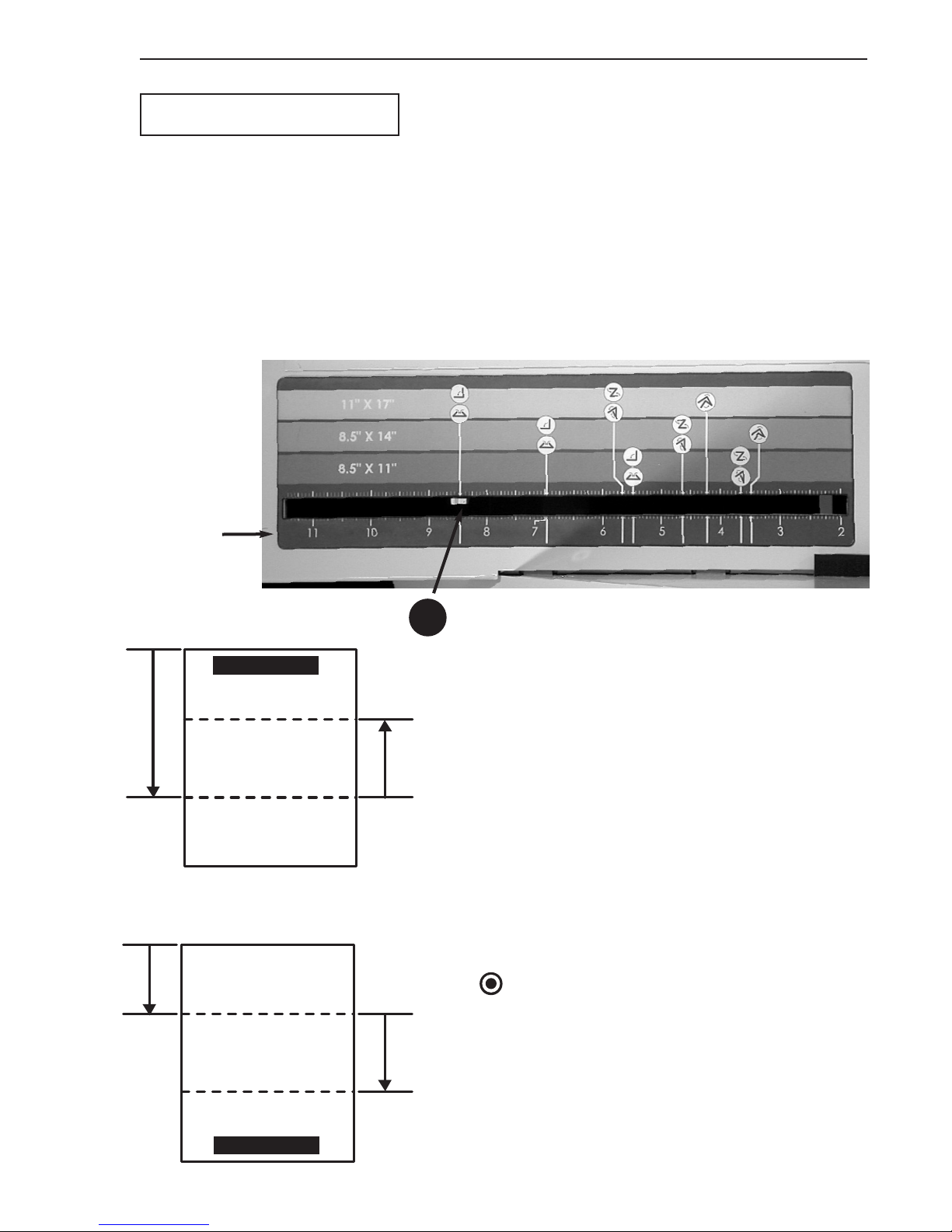
All custom folds are set up by first folding a
sample sheet into the desired fold, then measuring two distances:
1. From the leading edge to the first fold.
2. From the first fold to the second fold.
(See page 17 for folding sequences)
These distances are then set using the inch
scales on the fold tables. In the illustration,
the indicator (38) is set at 8.5".
The dimension of the first fold should be set
on the first fold table (to the right) and the
second on the second fold table (to the left).
Two measurement examples are illustrated.
Make fine adjustments to the fold lengths in
the same way as described for standard folds
(see page 16).
NOTE
Tr eat a single fold as if it were the second fold.
Set the indicator on the first fold table all the
way down to the single fold icons. Then set
the dimension to the fold on the inch scale on
the second fold table.
Tr a iling Edge
Tr a iling Edge
38
Inch
Scale
Zig-Zag Fold
First Fold
Second Fold
LETTERHEAD
First
Measurement
Second
Measurement
Letter Fold
First Fold
Second Fold
LETTERHEAD
First
Measurement
Second
Measurement
38. Fold Length Indicator
Page 22
20
Rev. 12/04
HF-400
Maintenance and Troubleshooting Operating Manual
Paper Jams
Paper jams can occur at all three
stages of the folding process. In the:
• Feed area
• Central folding area
• Exit area.
All these areas are easily accessible
without the use of tools as shown in
the following sections.
WARNING
Before attempting to clear any jam or
open any access panels, turn off the
main power switch (11) and remove
the power cord from the socket (9)
(see page 9).
CAUTION
Do not attempt to clear jams by poking sharp objects into the openings
or by cutting sheets wrapped around
rollers. Permanent damage to both
the resilient and metal rollers is likely as a result of any use of knives or
sharp objects. Remove jammed
sheets only by carefully pulling them
out or unwrapping them using only
your hands and fingers.
Feed Area Clearing
To clear a jam in the feed area:
1. Remove the document stack from
the feed table (31).
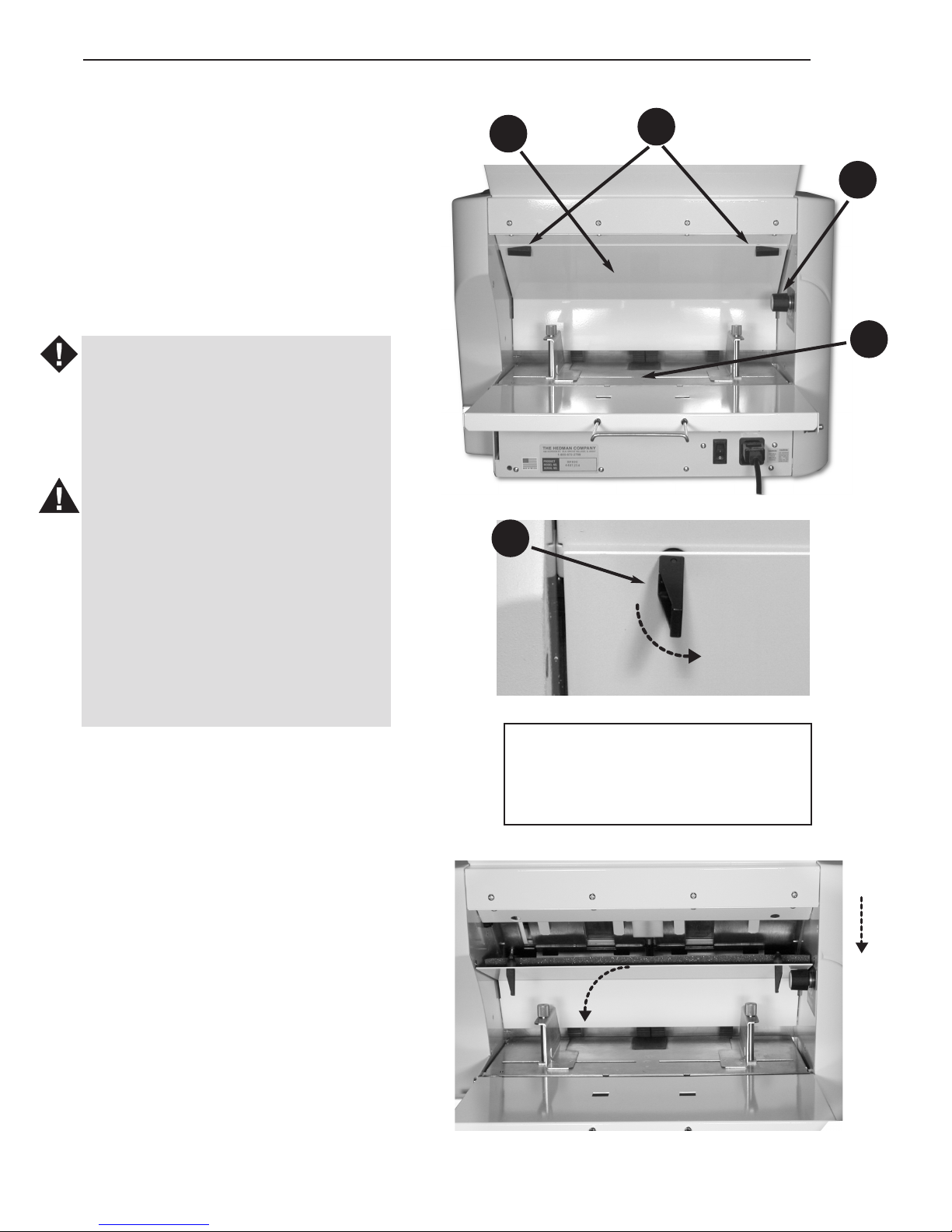
2. Release the two access panel latches (30) by rotating them down
and remove the access panel (29)
by pulling it out.
3. Clear the paper from the feed area.
30
29
30
REMOVE
LOWER
31
28
28. Paper thickness adjustment knob
29. Feed area access panel
30. Feed area panel latch
31. Feed table
Page 23
21
Rev. 12/04
HF-400
Operating Manual Maintenance and Troubleshooting
Feed Area Clearing
NOTE
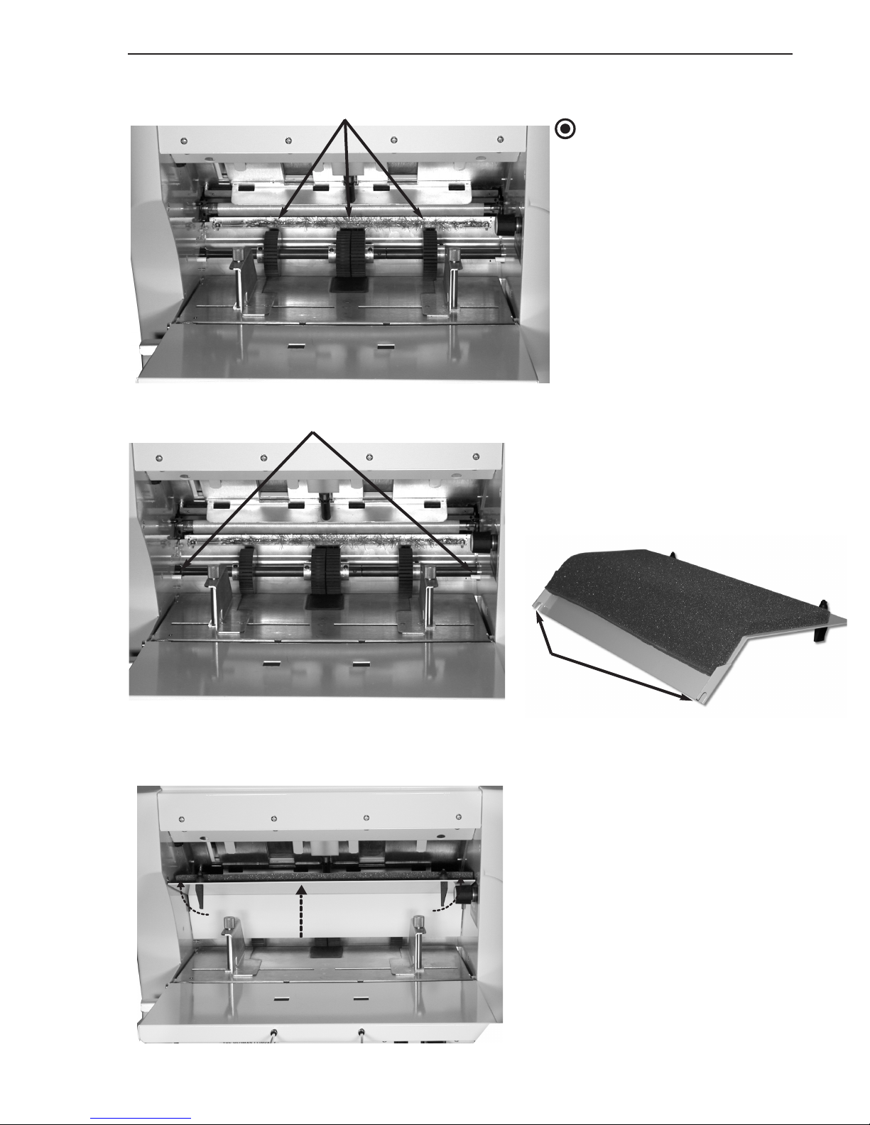
The feed rollers can be turned
by hand (in one direction only)
by pulling on the top of a roller
or by turning the axle.
After the jam is cleared:
1. Insert the access panel, keeping it above the paper thickness adjustment knob (28)
and being sure the notches
on the access panel (29)
engage the pins near the feed
roller axle.
2. Refasten the access panel by
raising it fully up to the mating
flange and rotating the two
latches to the locked position.
RAISE
FEED ROLLERS
PINS
NOTCHES
Page 24
22
Rev. 12/04
HF-400
Maintenance and Troubleshooting Operating Manual
Central Folding
Area Clearing
The folding process takes place in the
area within the fold tables. To reach
this area, both of the fold table tops
must be removed.
To clear a jam in the central folding area:
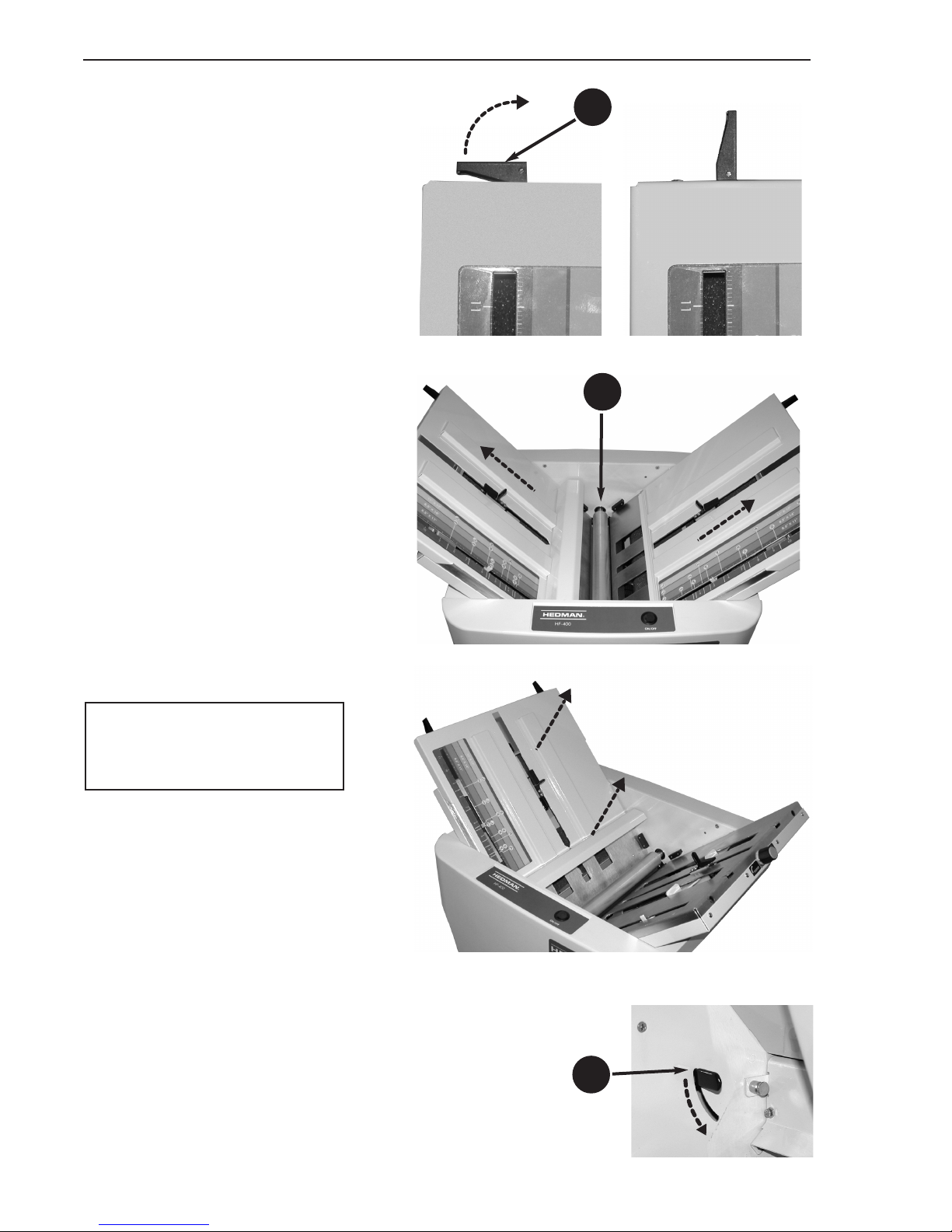
1. Release the two latches (39) at the
top of each fold table.
2. Move the fold stop levers (14) near
the center of the table to provide
clearance for removing the fold
table tops.
3. Slide each fold table top upward a
few inches to clear the guides at the
bottom, then lift it off the machine.
The top roller (40) and lower fold
tables will be visible.
25
39
40
25. Top roller release lever
39. Fold table latch
40. Top roller
Page 25
23
Rev. 12/04
HF-400
Operating Manual Maintenance and Troubleshooting
Central Folding Area
Clearing
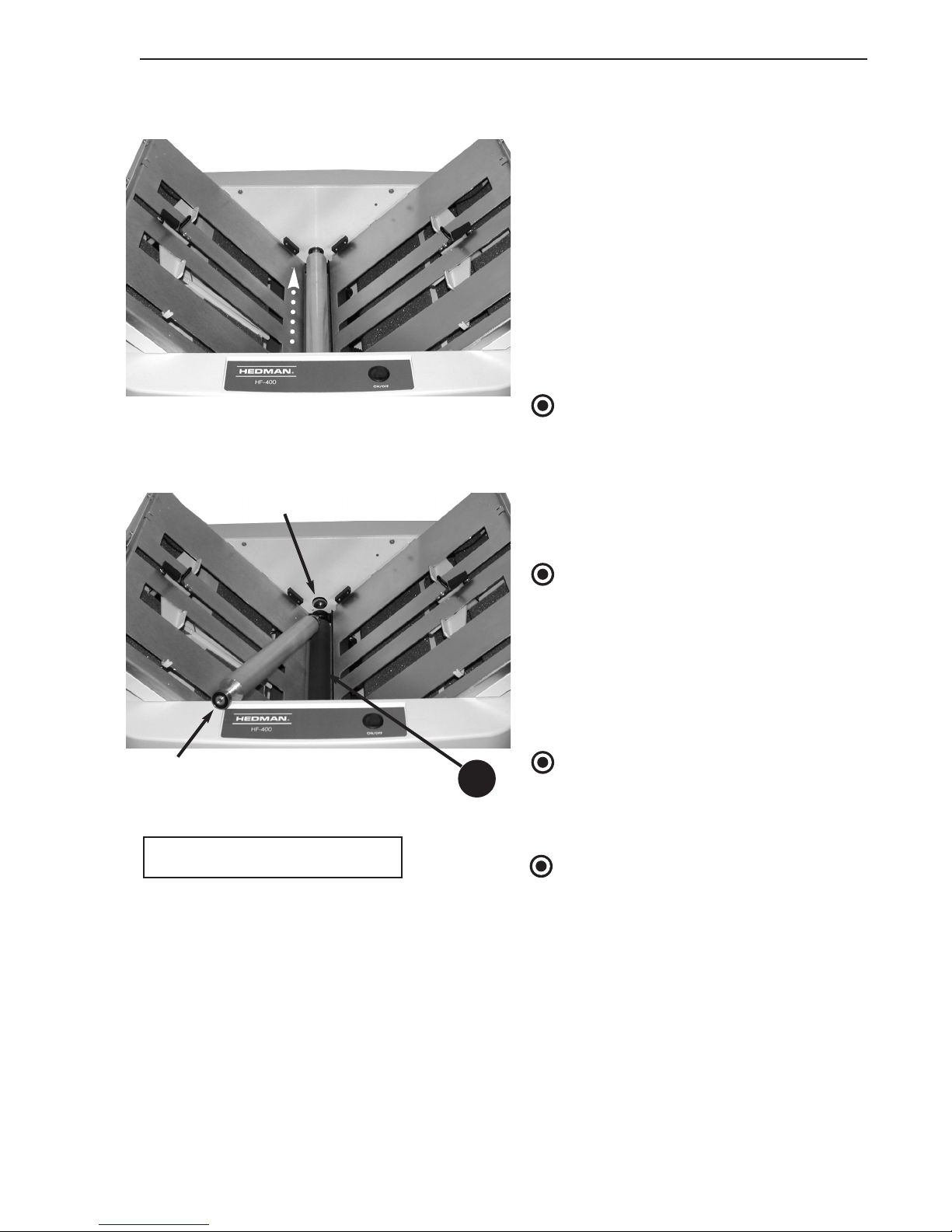
4. Release the two top roller release
levers (25) in the exit area.
5. Grasp the top roller and lift slightly.
Push straight into the far side until
the near end is clear of the side
frame. Rotate the near end of the
roller up and the roller out of the
bearing seat to remove it.
6. Clear the paper from the fold area.
NOTE
The bottom roller (41) can be rotated
by hand to unwrap sheets
7. Re-assemble the center fold area by
reversing the dis-assembly steps.
NOTE
Roller bearings are pressed onto the
ends of the top roller. When re-inserting the roller into the machine, be sure
the roller is centered between the side
frames and the bearings have settled
into their seats.
NOTE
Do not forget to re-engage (rotate
upward) the two top roller release
levers (25) in the exit area.
NOTE
The bottom roller is the most important one to be cleaned. Whenever it is
exposed, check it and clean if necessary
(see page 27).
BEARING
TOP ROLLER
BEARING SEAT
41
41. Bottom Roller
Page 26
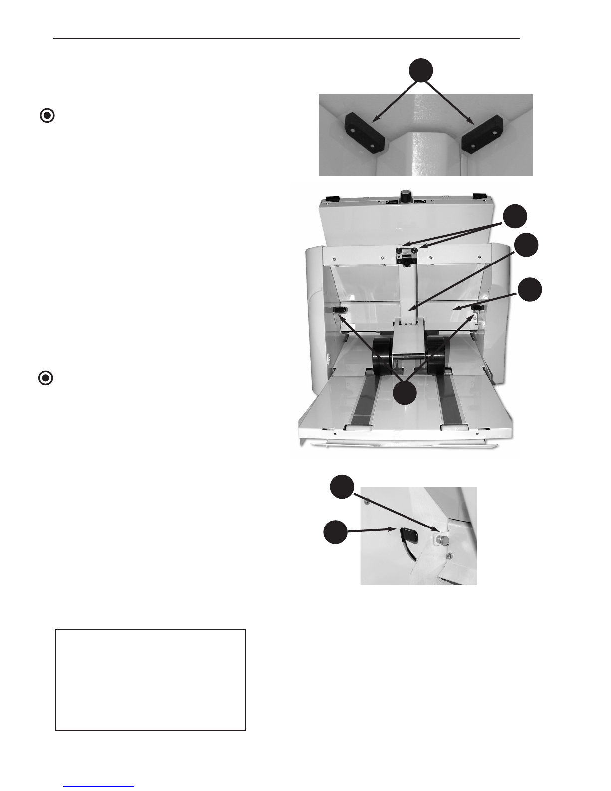
24
Rev. 12/04
HF-400
Maintenance and Troubleshooting Operating Manual
Central Folding Area
Clearing
NOTE
When sliding the fold table tops down
into position during re-assembly, be
sure both of them fit under the fold
table top guides (42) and the table tops
are slid completely in before rotating the
latches down to lock them in place. The
silver alignment tabs between the latches must be in the slots in the end of the
fold table top and flush with its surface.
Exit Area Clearing
To open the exit area of the HF-400,
the stacker assembly (21) must first be
removed. Refer to page 11 describing
the installation of the stacker assembly
and remove it by reversing the installation process.
NOTE
The top roller release levers (25) must
be engaged (up position) to allow the
door to swing down.
To clear a jam in the exit area:
1. Pull the two exit area door release
latches (24) and lower the door (23).
23
20
21
24
25
20. Stacker assembly thumb screw
21. Stacker assembly
23. Exit area access door
24. Exit area door latch
25. Top roller release lever
42. Fold table top guide
42
24
Page 27
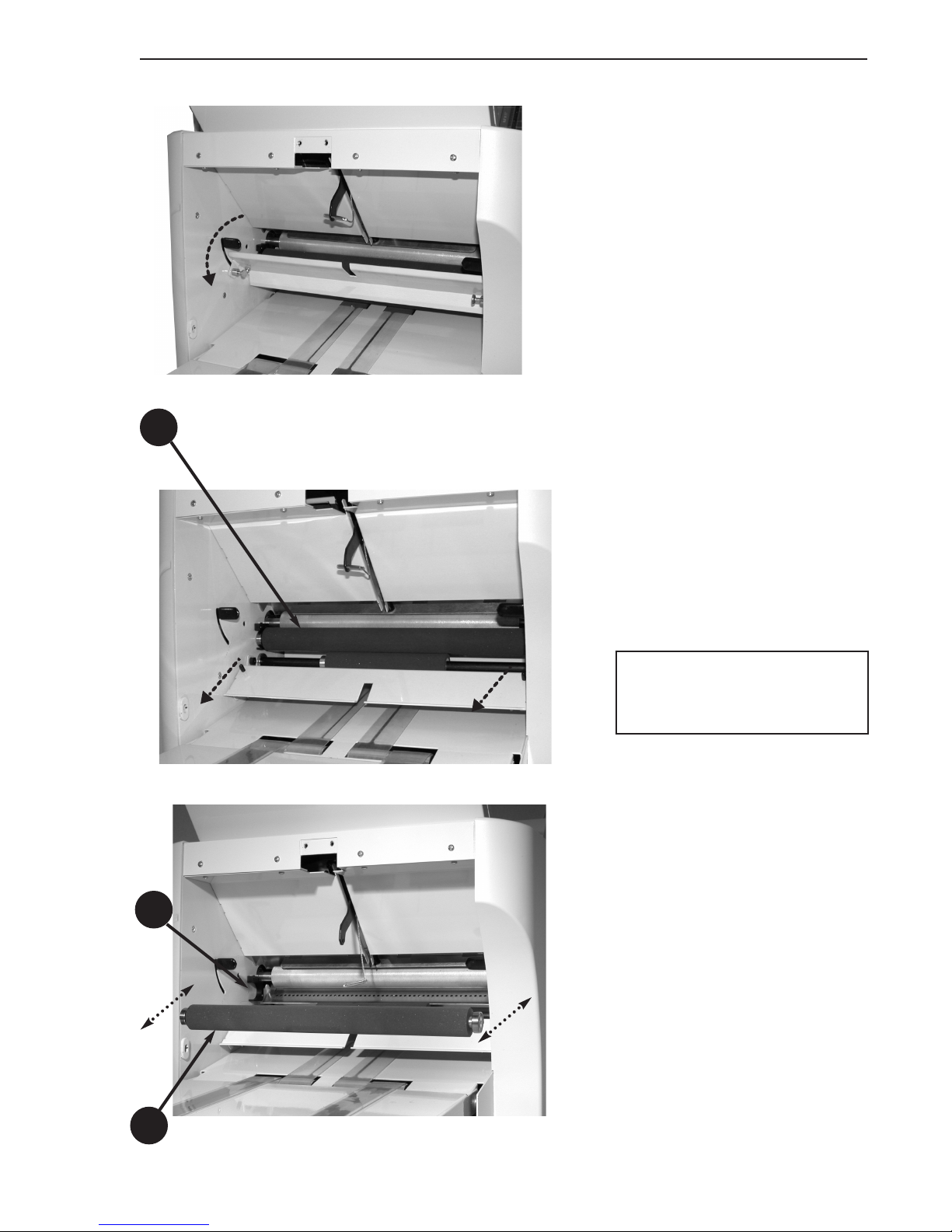
25
Rev. 12/04
HF-400
Operating Manual Maintenance and Troubleshooting
Exit Area Clearing
2. With the exit area access door
(23) fully lowered, grasp the foam
exit roller (43) at both ends and
pull it straight out of its C-shaped
bearing seats.
3. Clear the paper from the exit area.
4. Re-assemble the exit roller into its
bearing seats (44) by pushing it
straight into the bearing seats
until a light click is heard or felt.
5. Close the door and re-install the
stacker assembly.
43
43
44
23. Exit area access door
43. Exit roller
44. Exit roller bearing seat
Page 28
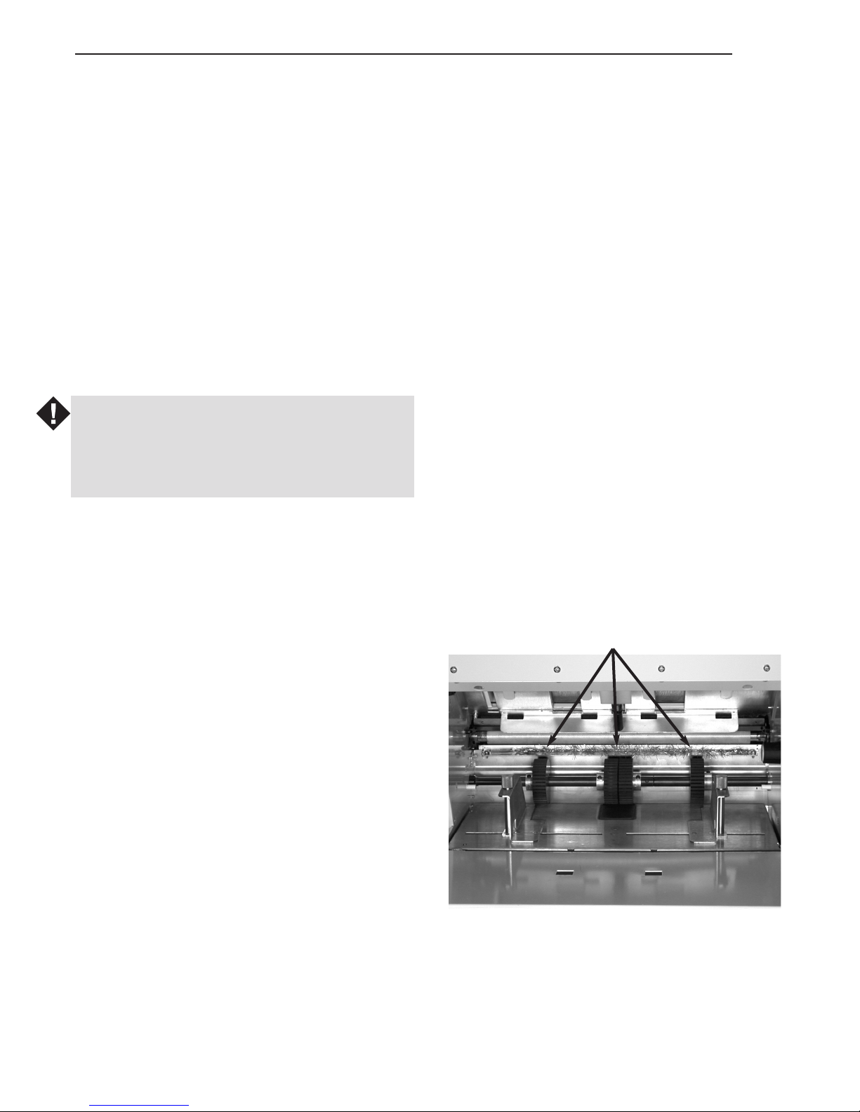
26
Rev. 12/04
HF-400
Maintenance And Troubleshooting Operating Manual
Cleaning
As the HF-400 is used, the feed, fold and exit
rollers can become coated with a build-up of
paper dust, ink or toner transferred from printed documents. This build-up can cause roller
traction to change and result in improper folds
due to slippage or hang-up between the rollers
and documents. It can also result in smudges
on folded documents from ink or toner being
re-transferred off the rollers.
If folds start to change without changing
machine settings or if smudges are observed,
stop the folding process and clean the rollers.
WARNING
Turn off the main power switch and pull the
power cord plug out of its socket before beginning any cleaning process.
To clean the rollers:
1. Refer to the paper jams section (pages 20 to
25) for instructions on gaining access to the
feed, fold and exit areas of the HF-400.
2. Use a clean cloth and isopropyl alcohol to
wipe the roller surfaces. If alternative cleaners are to be used, be sure they will evaporate
completely without leaving a soapy film on
the rollers.
FEED END
The four feed rollers can be rotated by hand.
Pull on the top surface of one of the rollers to
expose the entire surfaces for cleaning.
FEED ROLLERS
Page 29
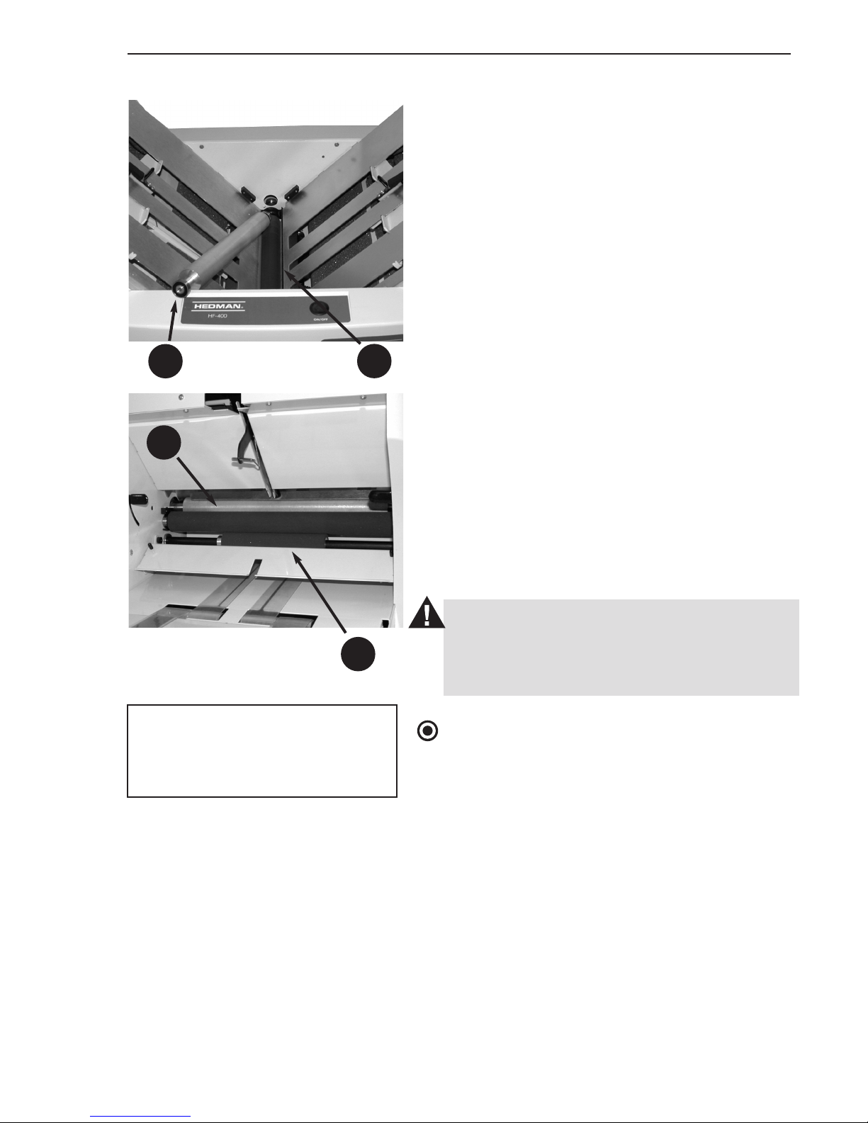
27
Rev. 12/04
HF-400
Operating Manual Maintenance And Troubleshooting
FOLD AREA
The top roller (40) can be cleaned after it has been
removed. With the top roller removed, the bottom roller (41) can be rotated by hand in both
directions to reach the whole surface. The bottom
roller should be thoroughly cleaned all the way
around. This is critical to proper operation.
EXIT END
The removable exit roller (43) can be cleaned
outside the machine. The fixed exit roller (45)
can be rotated on its axle by hand. It will also
move when one of the fold rollers is rotated.
Either way, the whole surface of the fixed exit
roller can be exposed.
3. Allow all surfaces to dry before reassembling
the components and closing the access panels.
CAUTION
Do not use strong solvents in the cleaning
process. The compounds in the rollers may be
damaged.
NOTE
Whenever the HF-400 is opened to clear paper
jams, it is a good idea to look at the rollers and
clean them if needed.
45
43
41
40
40. Top roller
41. Bottom roller
43. Exit roller (removable)
45. Fixed exit roller
Page 30
28
Rev. 12/04
HF-400
Maintenance And Troubleshooting Operating Manual
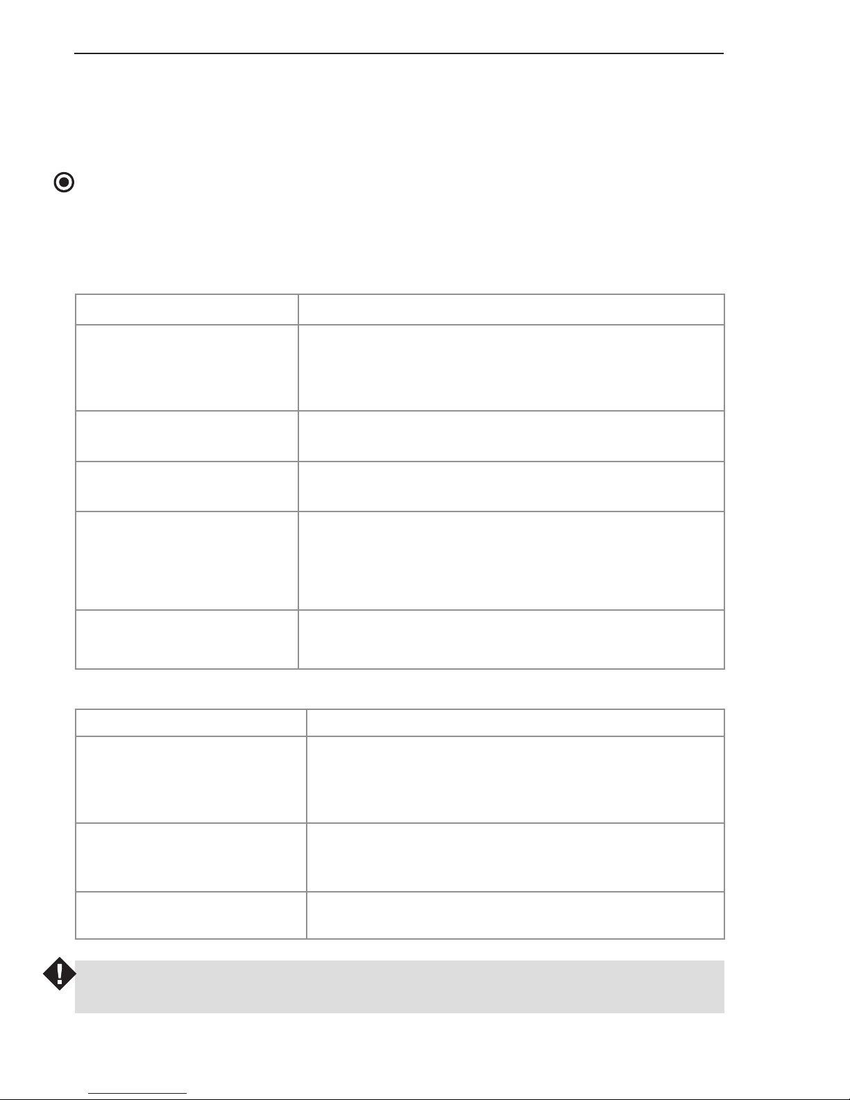
Troubleshooting
The following tables provide areas to check and corrective actions for some problems that may
arise.
NOTE
The start/stop switch on the top of the HF-400 should glow red when power is turned on and
all latches are properly closed to activate their associated safety interlocks. If that switch does
not glow, perform the checks in the first table until the switch is illuminated.
Machine will not run when start/stop switch is turned on:
WARNING
Before taking corrective action to clean rollers, be sure the power cord is disconnected.
Paper does not feed when start/stop switch is turned on:
Correction
Verify that the wall outlet has power and push plugs
all the way into sockets.
Tu rn on the main power switch.
Remove the power cord from the socket and check
the fuses (see page 9). Replace fuse if blown.
• Check that the fold tables are fully seated and that
the silver alignment tabs are in their slots
(see page 24).
• Close all fold table latches to activate safety
switches.
Clear paper jam.
Check
Is power cord plugged
into a live outlet and fully
inserted in the socket on
the machine?
Is the main power switch
turned on?
Is a fuse blown?
Are the fold tables fully
seated and latched?
Is there a paper jam in
the machine?
Correction
• Check for paper in feed area.
• Check that the feed table lever is up.
• Check that the paper has been fully inserted to the
stop before raising the feed table.
• Clean the feed rollers (see page 26).
• Change paper if possible. Some types of paper
(especially coated stock) do not feed well.
Loosen guides and readjust to be just snug against
the paper stack. Retighten guide lock knobs.
Check
Is paper properly loaded?
Are feed rollers slipping on
the top sheet of the paper
stack?
Are paper guides too tight?
Page 31
29
Rev. 12/04
HF-400
Operating Manual Maintenance And Troubleshooting
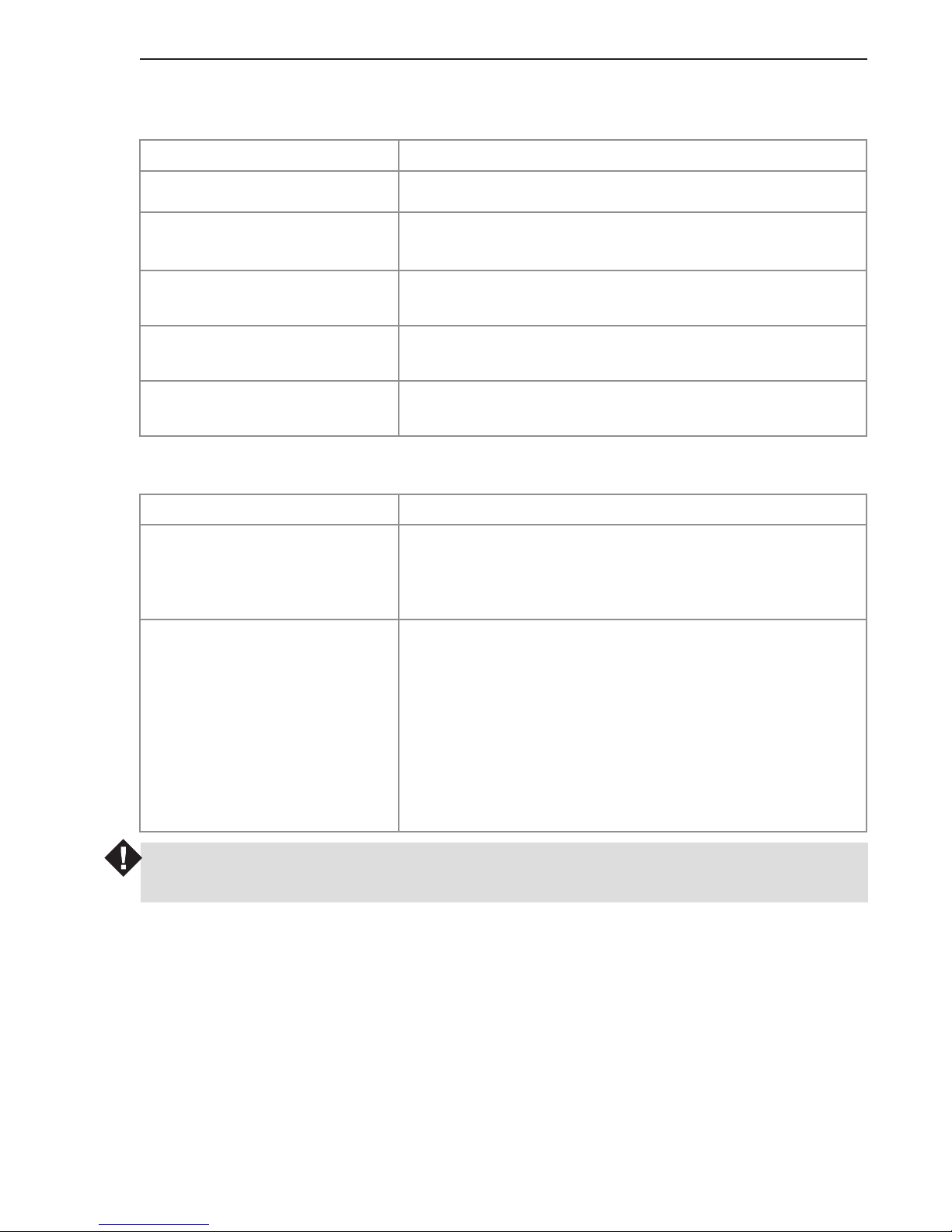
Paper feeds irregularly:
WARNING
Before taking corrective action to clean rollers, be sure the power cord is disconnected.
FACTORY TRAINED SERVICE
If the problem cannot be solved using these troubleshooting methods, contact the authorized
Hedman Dealer or Distributor for your location (see page 6) to obtain help from a factory
trained technician.
Should the problem be severe enough that the HF-400 must be returned to the factory, the
authorized Hedman Dealer or Distributor will properly package the machine to avoid damage
in transit.
Correction
Clean the feed rollers (see page 26).
Adjust the knob to the paper thickness being used
(see page 13).
Remove paper, bend the paper stack back and forth
to break the bonds, re-square the stack and reload.
Be sure that all sheets in the stack are even with one
another.
Remove and reverse curl the paper to flatten it, then
reload.
Check
Are the feed rollers clean?
Is the paper thickness knob
set properly?
Are paper sheets stuck to
each other?
Is the paper stack square?
Is the paper curled?
Fold quality is poor:
Correction
• Reset the fold dimensions and fine adjustments on
the fold tables (see pages 14 to 19).
• Clean the fold rollers under the fold tables (see
page 27)
• Be sure paper is loaded squarely on the feed table.
• Skew can be caused by running thick paper with
the paper thickness adjustment set for thin paper.
Adjust the knob (see page 13).
• Too much paper in the stack can cause skew.
Reduce stack to 400 sheets or less.
• Make correction with the skew adjustment knob
(see page 18).
• Clean the feed and fold rollers
(see pages 26 and 27).
Check
Are fold dimensions as
desired?
Are the folds square with
the edges of the paper?
 Loading...