

Heckler&Koch MR556A1 User Manual

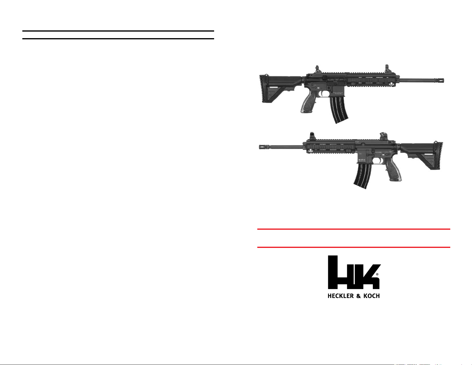
MR556A1
OPERATOR’S MANUAL
Covering MR556A1
5.56 x 45 mm Rifle &
MR556A1 Upper Receiver Kit
SAFETY PRECAUTIONS
CAUTION: Read these safety rules before handling the firearm!
Read this operators manual before handling your firearm. The following safety rules
are placed in this manual by HK as an important reminder that firearms safety is your
responsibility. If handled improperly firearms can be dangerous and can potentially cause
damage to property, serious injury, or death.
1. Never point a firearm at anyone, or in any direction other than a SAFE direction, i.e.
downrange.
2. Treat all firearms as if they are always loaded.
3. Keep your finger off the trigger and outside of the trigger guard until your sights are
aligned on the target.
4. Keep your finger off the trigger and outside of the trigger guard while loading or
unloading the firearm.
5. Keep your finger off the trigger and outside of the trigger guard while slinging the
firearm or while carrying it.
6. Be sure of your target and the back stop beyond.
7. Never give a firearm to or take a firearm from anyone unless the action is open and
the magazine and/or chamber are free of any ammunition or brass.
8. Be sure that the ammunition you are using is factory loaded, is of the correct caliber
for the firearm in which it is to be used, and that it is not damaged in any way.
9. Before firing, remove the magazine from the firearm, lock the bolt open, make
sure the chamber is clear of any ammunition or brass, and check the barrel of the
unloaded firearm for any possible obstructions.
10. Before firing any firearm that is unfamiliar to you, make sure that you understand
exactly how it functions. A lack of familiarity with the firearm can result in serious
accidents. Attend a certified training course on any firearm which you intend to use or
with which you are not sufficiently familiar.
11. Always wear hearing and eye protection when using your firearm.
12. Keep all body parts, particularly the hands and fingers, away from the muzzle to avoid
injury or burns.
13. Be sure that parts of the hand do not touch or interfere with the action.
14. Firearms should be stored separately from ammunition and beyond the reach of
children, and/or any untrained individuals.
15. Avoid the use of any alcoholic beverages or drugs before and during the use of any
firearm.
16. Discharging firearms in poorly ventilated areas, cleaning firearms, or handling
ammunition may result in exposure to lead, a substance known to be associated with
birth defects, reproductive harm, and other serious injury. Have adequate ventilation
at all times. Wash hands thoroughly after exposure.
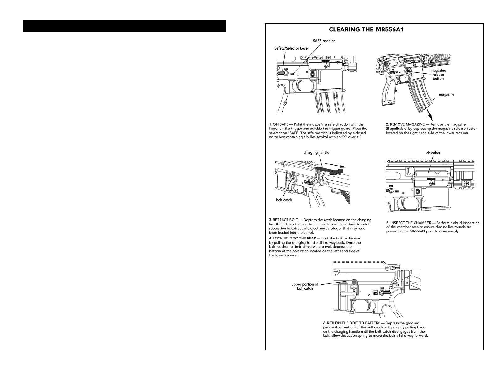
17. To make the firearm safe, one must ensure the chambered round is removed during
the clearing procedure. Removal of the rifle’s magazine does not remove the
chambered round. This can only be done with the rearward movement of the bolt
after the magazine is removed.
MR556A1
OPERATOR’S MANUAL
Covering the MR556A1 5.56 x 45 mm Rifle
and MR556A1 Upper Receiver Kit
WARNING: A firearm has the capability of taking your life or the life of someone else!
Be extremely careful with your firearm. An accident can occur at anytime and is almost
always the result of not following basic safety rules.
STOP! KNOW HOW TO CLEAR THIS FIREARM BEFORE ATTEMPTING TO OPERATE.
SEE PAGE 5
© Heckler & Koch, 1/11, 4/11, 4/12, Revised July 2013
Global Website: www.heckler-koch.com • American Website: www.hk-usa.com
Every attempt has been made to ensure the accuracy of this information, however errors or changes
may occur. Specifications and models subject to change without notice.
Tel: (706) 568-1906 • Fax: (706) 568-9151
All rights reserved
Heckler & Koch
5675 Transport Boulevard
Columbus, Georgia 31907
4
5
TABLE OF CONTENTS
Safety Precautions ................................................................... Inside Cover
Clearing ......................................................................................................5
Section 1 Introduction ................................................................................................6
Section 2 Nomenclature and Description .................................................................7
Section 3 Function and Op er a tion ..........................................................................12
Section 4 Sights, Sight Adjustment and Aiming ......................................................15
Section 5 Ammunition ..............................................................................................19
Section 6 Instructions for Use ...................................................................................20
Loading the Magazine .............................................................................20
Loading the Rifle ......................................................................................20
Firing the Rie ..........................................................................................22
Unloading the Rifle ..................................................................................23
Section 7 Disassembly and Assembly ......................................................................24
Disassembly of the MR556A1 ..................................................................24
Assembly of the MR556A1 .......................................................................30
Function Check .......................................................................................37
Magazine Disassembly .............................................................................38
Magazine Assembly .................................................................................40
Section 8 Cleaning and Main te nance .....................................................................42
Lubrication ...............................................................................................43
Section 9 Troubleshooting Prob lems and Re pair ....................................................46
Section 10 Exploded Diagram and Parts List ............................................................48
Section 11 Specifications ...........................................................................................51
Warranty Registration ...............................................................................51
Section 12 MR556A1 Upper Receiver Kit Supplement ..............................................52
Firearms Service Record ....................................................................................................56
6
7
SECTION 1 — INTRODUCTION
A direct descendent of the HK416, the MR556A1 is a semi-automatic rifle developed by
Heckler & Koch as a premium level commercial/civilian firearm with match rifle capability.
Like the HK416, the MR556A1 is a major product improvement over conventional AR-type
carbines and rifles. The MR556A1 uses the HK proprietary gas piston operating system,
employing a piston and a solid operating “pusher” rod in place of the gas tube normally
found in AR15/M16/M4-style firearms.
This method of operation virtually eliminates malfunctions that are common to direct
impingement gas systems since hot carbon fouling and waste gases do not enter the
receiver area. This is the same key feature critical to the success of the HK416 rifles used
by leading military and law enforcement customers. The MR556A1 is manufactured in the
USA using American and German made components. The MR556A1 uses many of the
same assemblies and accessories originally developed for the HK416 including the HK
free-floating four-quadrant rail system.
The HK Free Floating Rail System (FFRS) handguard has four MIL-STD-1913 Picatinny
rails and allows all current accessories, sights, lights, and aimers used on M4/M16-type
arms to be fitted to the MR Series. The HK rail system can be installed and removed with
simple tools and returns to zero when reinstalled. The MR556A1 also has a Picantinny rail
machined into the top of its upper receiver for mounting optics and mechanical sights.
Unlike earlier prototypes, major subassemblies, including the MR556A1 upper receiver/
barrel assembly, are fully interchangeable with other high quality AR-style firearms.
MR556A1 upper receiver kits can be used to retrofit competing legacy AR systems.
Like the famous HK416, the MR556A1 uses a German-made barrel produced by Heckler
& Koch’s famous cold hammer forging process. The highest quality steel is used in this
unique manufacturing process producing a barrel that provides superior accuracy and
long service life. But unlike the HK416, the MR556A1 does not use a chrome-lined barrel.
Chrome-lining can sometimes mask bore imperfections and negatively affect accuracy. For
the new series of Heckler & Koch semi-automatic MR rifles, HK designers and engineers
believe best accuracy comes with an unlined bore.
Used with the HK Free Floating Rail System, the barrel does not touch the handguard,
ensuring the barrel is truly free-oating for maximum accuracy. The unchromed barrel
has an internal profile of 6 lands and grooves with a 1 in 7 inch (178 mm) twist. It is also
moderately “swagged” with a slightly smaller internal diameter at the muzzle end than the
chamber end. This feature has a positive effect on bullet accuracy and velocity. The thick,
heavy contour 16.5-inch MR556A1 barrel also contributes to its excellent accuracy.
A precise enhanced two-stage trigger adds significantly to the accuracy of the MR5556A1
and an extended latch charging handle makes operating the rie with a telescopic sight
easier. The retractable buttstock can be locked into a solid, non-moving position by
tightening an Allen screw in the bottom of the stock. Special target rifle takedown pins
ensure the upper and lower receivers are firmly mated for accurate performance.
Designed to function with a wide variety of high quality 5.56 x 45 mm ammunition, the
MR556A1 uses a C.I.P. dimensioned chamber (a chamber with dimensions specified by the
Commission Internationale Permanente). The MR556A1 also functions reliably with most
quality Caliber .223 Remington ammunition. The MR556A1 is being produced with the
same commitment to quality as German-made HK firearms. By using joint U.S./German
manufacturing, Heckler & Koch leverages the relative strengths of two continents to
make the preeminent AR-type firearm, combining the design innovations of the USA and
Germany into one new product.
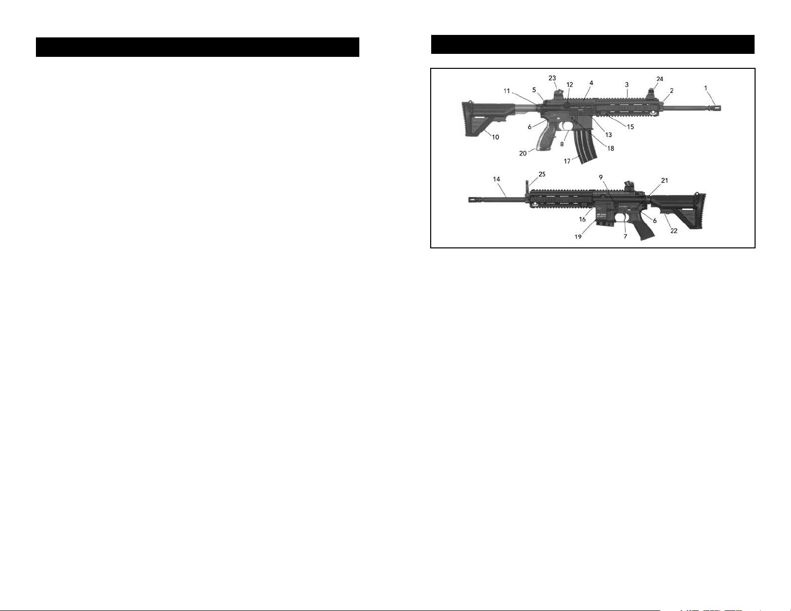
SECTION 2 — NOMENCLATURE & DESCRIPTION
Fig. 1 – MR556A1 Right and Left Views
1. Compensator – Bird cage style flash hider is screwed to the end of the barrel and helps
compensate for muzzle rise during firing.
2. Gas Block – Directs the expended gas from the gas port hole in the barrel and pushes
the piston rearward, pushing the piston rod and bolt carrier rearward (defined in more
detail in the cycle of operation). Contains an attachment point for the optional HK folding
front sight.
3. Free Floating Rail System (FFRS) – The HK FFRS is a free-oating detachable rail system
with four-quadant MIL-STD-1913 (Picatinny) rails that can mount a variety of accessories
including sights, scopes, a forward grip, lights, laser aimers, bipods, and sling hardware.
The bore sight alignment of aiming devices is repeatable (no re-zeroing required) when the
Free Floating Rail System is removed and reinstalled on the rearm. The Free Floating Rail
System is removed and reinstalled with a 5 mm Allen wrench.
4. Upper Receiver – The upper receiver is a flat-top design with an integral MIL-STD-1913
(Picatinny) rail that provides support for the barrel, FFRS, gas system, and bolt carrier
assembly. It has a case deflector and ejection port. It connects to the barrel and barrel
socket. The piston rod is guided through the upper receiver by a bushing and activates the
bolt carrier. The charging handle is a part of the upper receiver as is the forward assist and
ejection port cover. The upper receiver is made from an aluminum forging.
5. Charging Handle – Allows the operator to chamber or clear a round and cock the
firearm. It also provides for initial charging of the firearm. The charging handle is locked in
the forward position during firing to prevent injury to the operator. An enhanced charging
handle with an extended catch is available on the MR556A1.
6. Selector/Safety Lever – Allows the operator to select the mode of fire and place the
firearm on safe. The selector lever is manually activated and unlike competing AR systems,
can be switched to safe even if the hammer is not cocked.

8
9
7. Trigger – When activated by the operator, initiates the firing sequence. Located inside
the lower receiver, the trigger when squeezed with the firearm loaded and off “safe” will
re the gun, “SEMI-AUTOMATIC” will re one round each time the trigger is pulled. The
MR556A1 uses a proprietary HK two-stage trigger for optimal accuracy.
8. Trigger Guard – The trigger guard protects the trigger. It can be lowered by depressing
the detent with a pointed implement, allowing the use of heavy gloves or mittens to be
used to fire the rifle.
9. Bolt Catch/Bolt Release – The bolt catch/release is manually operated. When the bolt
carrier is pulled fully to the rear, the bottom of the bolt catch/release is pressed by the
operator and then the bolt will be captured. To release the bolt, simply press the top of
the bolt catch/release. The bolt catch/release is also automatically activated when firing
the last round in a magazine.
10. Sliding Buttstock – Attached to the rearm via the receiver extension. The sliding
buttstock is ambidextrous and adjustable to 6 positions for length of pull by pressing in
on the rear portion of the Release Lever. It also contains the rear sling attachment points.
Many optional buttstocks can be attached to the MR556A1 as long as they fit on the
Receiver Extension (Buffer Tube), which has MIL-SPEC cross sectional dimensions.
11. Forward Assist – Ensures that the bolt is fully closed and locked. The forward assist is
used when a round is not fully chambered. You can push on the forward assist until the
bolt seats the cartridge fully into the chamber. It will return to its rearward position by
spring pressure. It can also be used to silently load the firearm.
NOTE: Both the pivot pin and the rear takedown pin are special precision “target rifle”
pins. For disassembly and reassembly, a center detent in the shaft of the pin must be
engaged under pressure and held to move the pins back and forth. DO NOT FORCE
THE PINS. Forcing the pins could damage the rifle and such damage is not covered
under the HK warranty. Contact HK Customer Service with any questions, TEL: 706568-1906, EMAIL: cs@heckler-koch-us.com.
17. Magazine – Holds cartridges ready for feeding and provides a guide for positioning
cartridges for stripping and chambering. The magazine provides reload capabilities for
sustained firing. The HK 30-round steel magazine and optional 20-round steel magazine
have a steel follower that will not cant during the feeding process. The spring is stronger
and more reliable than standard magazine springs. The MR556A1 can be used with other
high quality magazines of all capacities.
18. Magazine Catch/Magazine Release – Holds the magazine (in place) in the magazine
well and allows the operator to release the magazine and remove it from the firearm. The
magazine catch is activated automatically when the magazine is properly inserted into the
magazine well. The magazine catch is spring loaded and when the button is depressed,
the magazine will drop free from the firearm when this control is activated.
19. Lower Receiver – Contains the fire control system for the firearm. The lower receiver
contains the hammer, trigger, disconnector, sear, magazine well, magazine catch/release,
bolt catch/release, selector/safety lever, buttstock assembly with buffer and recoil spring,
pistol grip and trigger guard. The lower receiver is made from an aluminum forging and
provides a beveled magazine well to ease reloading.
12. Case Deflector – Built into the upper receiver, deflects the cartridge cases away from
the operator.
13. Ejection Port Cover Assembly – The ejection port cover is attached to the upper
receiver and is spring loaded. It will open automatically if the charging handle is pulled
to the rear or if the firearm is fired and can be manually closed at any time. It closes over
the ejection port to prevent sand, dust, etc. from entering the chamber. It should remain
closed when the firearm is not being fired.
14. Barrel Assembly – The chamber accepts the cartridge for firing and directs the
projectiles down range. The barrel is cold hammer forged and has standard land and
groove rifling with a 178 mm (1 in 7 inch) twist. The barrel is pressed into the upper
receiver assembly and held in place by the threaded barrel nut.
15. Locking Screw, Free Floating Rail System (FFRS) – The Free Floating Rail System is
fastened with the locking screw to the forward extending barrel locking bushing. Fastening
and positioning of the Free Floating Rail System on the bushing is positive and ensures
maintenance of zeroing on any sight system which has previously been attached to the rail
after removal and remounting of the rail. The Locking Screw is captive and should not be
completely removed, it can be tightened and loosened by using a 5 mm Allen wrench.
16. Pivot Pin – The pivot pin allows the upper receiver to pivot when the rear takedown pin
is depressed. When both the pivot pin and rear takedown pin are depressed, the upper
and lower receiver groups can be separated. The pivot pin is captive and should not be
removed. Both the pivot pin (front takedown) and rear takedown pin have locking shafts
that need to be pressed while the pins are depressed and engaged.
20. Pistol Grip – The pistol grip is made so it can be used by a left or right handed shooter.
It has a trapdoor on the bottom so extra batteries, small tools, or other accessories may be
stored. Other AR-type pistol grips can also be installed.
21. Rear Takedown Pin – When the rear takedown pin is depressed, it allows the upper
receiver to pivot on the front pivot pin. This pin is captive and should not be removed. Like
the pivot pin (front takedown pin), the rear takedown pin has a locking shaft that needs to
be pressed while the pins are depressed and engaged for disassembly and reassembly.
22. Buttstock Release Lever – The buttstock release lever locks the telescopic buttstock to
the tubular rear buttstock extension. The buttstock is adjustable in length in 6 positions.
23. Rear (Diopter) Sight – proprietary HK sight used on many HK firearms, attaches to the
MIL-STD-1913 top rail of the upper receiver.
24. Front Sight – proprietary HK sight used on many HK rearms, attaches to the MIL-STD1913 top rail of the Free Floating Rail System (FFRS).
25. Front (Flip up) Sight – proprietary HK sight attaches to the gas block, folds down when
not in use.
INTERNAL PARTS NOMENCLATURE
Muzzle – The muzzle is the area at the end of the barrel and the last area that the projectile
touches before it exits the bore.
Bore – The part of the barrel that the projectile travels through from the chamber to the
muzzle and contains lands and grooves which make the projectile rotate.
Chamber – The chamber is the area where the cartridge is seated and the initial phase of
firing occurs.
10
11
Bolt and Carrier Assembly – Provides stripping, chambering, locking, ring, extraction, and
ejection of the cartridges using the recoil spring and projectile propellant gases for power.
These parts are made of the highest quality steel.
Bolt – The bolt locking lugs rotate and lock the barrel and bolt together prior to cartridge
ignition.
Extractor – The extractor grabs the rim of the cartridge case and pulls the case out of the
chamber. The extractor spring and buffer provide constant pressure on the rim until the
case is ejected.
Ejector – The ejector pushes against the cartridge base under constantly spring tension
and once the cartridge or case is extracted and clears the front of the ejection port, the
cartridge or case is ejected from the firearm.
Cam Pin – The cam pin allows the bolt to cam inside the bolt carrier, which allows the bolt
to lock into the barrel extension when fully forward and cams to unlock when the carrier is
pulled to the rear.
ASSEMBLY GROUPS
Firing Pin – The ring pin will strike the primer and initiate the ring sequence once the
trigger is pulled. The firing pin will only protrude through the face of the bolt when the
bolt is fully locked forward.
Firing Pin Safety Spring – Prevents an accidental discharge in the event of dropping or
jolting the gun.
Firing Pin Retaining Pin – Retains the ring pin in the bolt carrier.
Recoil spring and buffer – The recoil spring provides constant pressure on the bolt carrier
and holds the bolt in a locked forward position. The buffer has tungsten granules that act
as a anti-bounce back mechanism. One type of buffer serves all barrel lengths.
Buffer detent – Captures the buffer and spring and when depressed, releases them for
removal.
Hammer – The hammer, when released by the trigger, strikes the firing pin. The hammer
returns when the bolt carrier pushes back under recoil, the hammer makes contact with
the disconnector and will release from the disconnector when the trigger is released. The
hammer remains cocked under spring pressure.
Trigger – The trigger, when squeezed, releases the hammer and returns under spring
tension.
Disconnector – Captures the hammer when it is cocked to the rear and releases the
hammer to the sear when the trigger is released. The disconnector then returns to its
original position under spring tension.
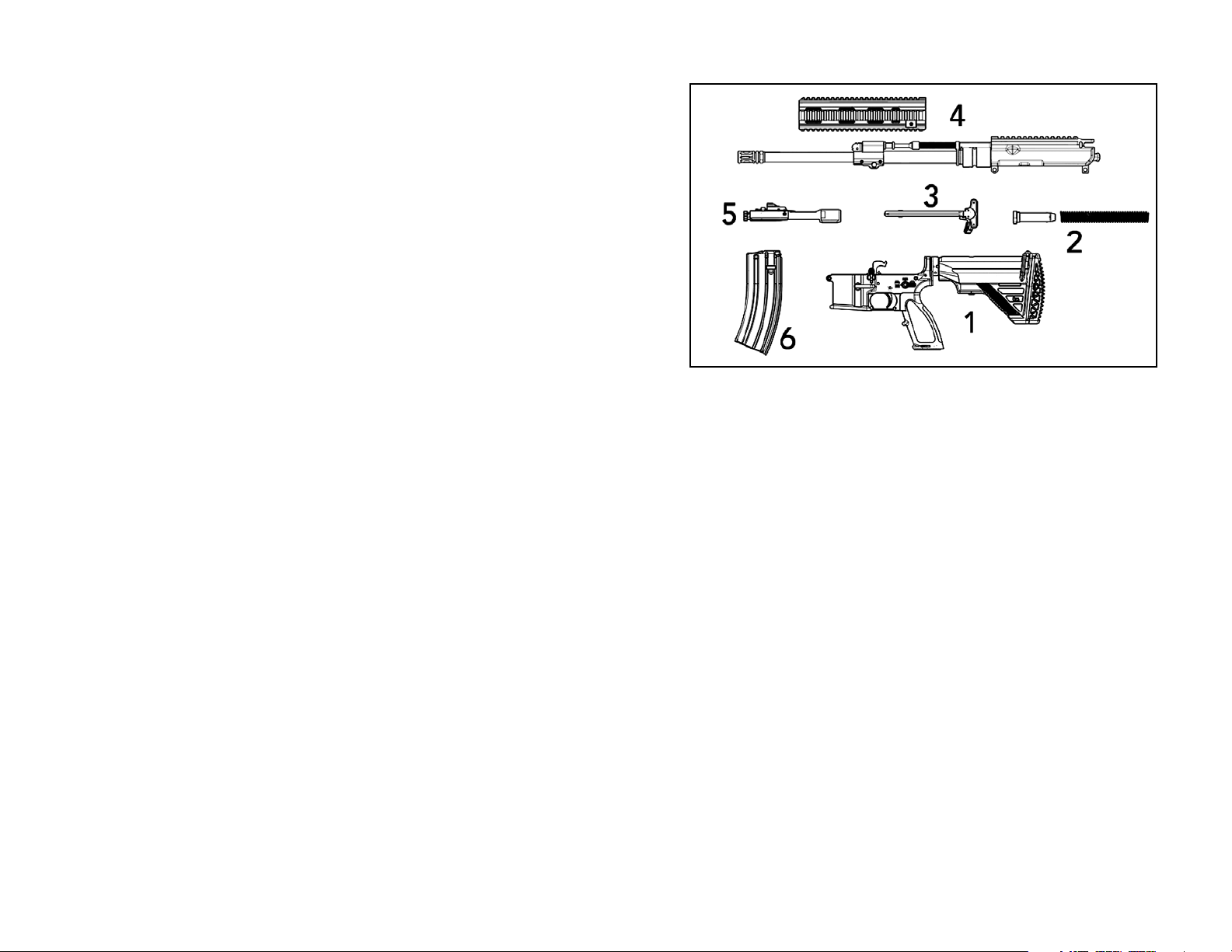
Fig. 2 – MR556A1 Major Assembly Groups
1. Lower Receiver Assembly - contains the Buttstock assembly (holds buffer and recoil
spring), pistol grip, selector lever, trigger group, trigger guard, magazine catch/
release, bolt catch/release, magazine well, pivot pin and take down pin.
2. Buffer and Recoil Spring
3. Charging Handle Assembly
4. Upper Receiver Assembly - contains the forward assist, case deflector, ejection port
cover assembly, Free Floating Rail System, gas block (with folding front sight point),
compensator, barrel, gas piston and piston rod.
5. Bolt Carrier Assembly
6. Magazine Assembly
12
13
SECTION 3 — FUNCTION AND OPERATION
The function and operation of the MR556A1 is similar to that found in semi-automatic
rearms and consists of eights steps: (1) Feeding, (2) Chambering, (3) Locking, (4) Firing,
(5) Unlocking, (6) Extracting, (7) Ejecting, and (8) Cocking.
These eight steps are explained below with a brief description of what occurs inside the
rifle during each step. Assume that a full magazine is loaded in the rifle with the magazine
follower spring forcing the follower and thus the top cartridge into the path of the bolt and
the bolt is locked to the rear.
(1) Feeding. The bolt is released from the bolt catch, either by deploying and then
releasing the charging handle or by depressing the bolt catch. The bolt assembly moves
forward, being driven by the expansion of the recoil spring. The bottom locking lugs on
the bolt head act as a feed pawl, striking the top cartridge off the magazine and moving
the cartridge towards the chamber in rear of the barrel.
(2) Chambering. The recoil spring continues to drive the bolt assembly forward until the
bolt head seats the cartridge into the barrel’s chamber. Chambering is complete when the
extractor snaps into the extracting groove on the cartridge and the ejector is forced into
the face of the bolt.
(3) Locking. Locking occurs when the bolt reaches its limit of forward travel. When the
bolt is moving forward, the cam pin orients the bolt head by ensuring that the locking
lugs on the bolt head will pass between the gaps of the locking lugs located on the barrel
extension (chamber). The bolt then strikes the back of the barrel and then stops. The
action spring continues to move the bolt head carrier forward, thus causing the cam pin
to pivot on the bolt head’s raceway. This action pivots the bolt head and rotates the bolt
head’s locking lugs counter-clockwise until they engage the locking lugs on the barrel
extension. The bolt assembly is now locked into the upper receiver.
(7) Ejecting. Ejecting throws the empty cartridge case out of the receiver. As soon as the
bolt has drawn the cartridge case clear of the chamber, the force of the ejector spring and
plunger pushes the cartridge case head away from the bolt face. This causes the forward
end of the cartridge case to move outward to the right. A deflector on the outside of the
upper receiver deflects the cartridge case away from operator.
(8) Cocking. Cocking occurs when the hammer is forced into position for ring the next
cartridge. This happens as the bolt carrier assembly travels toward the rear. The bolt
carrier assembly forces the hammer back and rides over it. The hammer is caught by the
disconnector if the trigger is still held to the rear and by the trigger’s sear surface if the
trigger has been released.
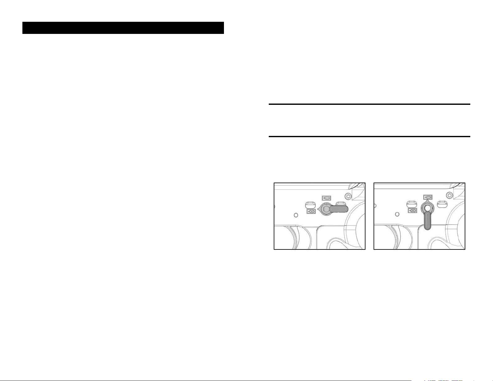
SELECTOR/SAFETY LEVER FUNCTION
NOTE: The MR556A1 has ambidextrous selector/safety levers, that is safety levers
located on both sides of the lower receiver. Either lever can be manipulated and
moves the lever on the other side. Unlike many AR-style firearms, the selector/safety
levers of the MR556A1 can be placed on the “SAFE” position even if the MR556A1
is not cocked.
“SAFE POSITION” – Place the selector lever with the point facing towards the closed
white box containing a bullet symbol with an “X” over it (towards the muzzle, Fig. 3).
“SEMI-AUTOMATIC POSITION”– Place the selector lever with the point towards the
closed red box containing a red bullet symbol in it (straight up position) (Fig. 4).
(4) Firing. Firing occurs when the ring pin strikes the primer in the head of the cartridge.
When the trigger is pulled, the trigger’s sear surface disengages from the hammer’s
intercept notch and the hammer releases. The hammer moves forward under pressure
from the hammer spring, disengaging the drop safety, striking the firing pin, and
overcoming the inertia of the firing pin spring. This drives the firing pin against the primer,
which in turn ignites the propellant in the cartridge case and propels the bullet through the
barrel.
(5) Unlocking. Unlocking occurs after a cartridge is fired. As the bullet is forced through
the barrel by expanding gases, a small amount of gas enters through the gas port into the
gas block. The gas block features a small expansion chamber that quickly lls up with gas.
The gas then hits the front of the gas piston, causing the three piston rings to expand, and
driving the gas piston rearwards. Because the pusher rod is mounted in the gas piston, the
pusher rod moves back as well. The back of the pusher rod hits the anvil (string surface)
on top of the bolt head carrier, causing the bolt head carrier to move rearwards. As the
bolt carrier assembly moves rearward, the bolt cam pin rotates and unlocks the bolt from
the locking lug recesses in the barrel extension. The unlocked bolt is now ready to move
rearward. Any remaining gas follows the bullet out of the muzzle.
(6) Extracting. Extracting removes the empty cartridge case from the chamber. As the
bolt unlocks, the bolt rotates slightly counterclockwise, causing the extractor to rotate the
cartridge case within the chamber. The expanded case breaks contact with the chamber
walls, allowing extraction to occur.
Fig. 3 – SAFE Fig. 4 – SEMI-AUTO
14
15
SECTION 4 — SIGHTS, SIGHT ADJUSTMENT, AND AIMING
MR556A1 rifles can accommodate a wide variety of optical and mechanical (iron) sights.
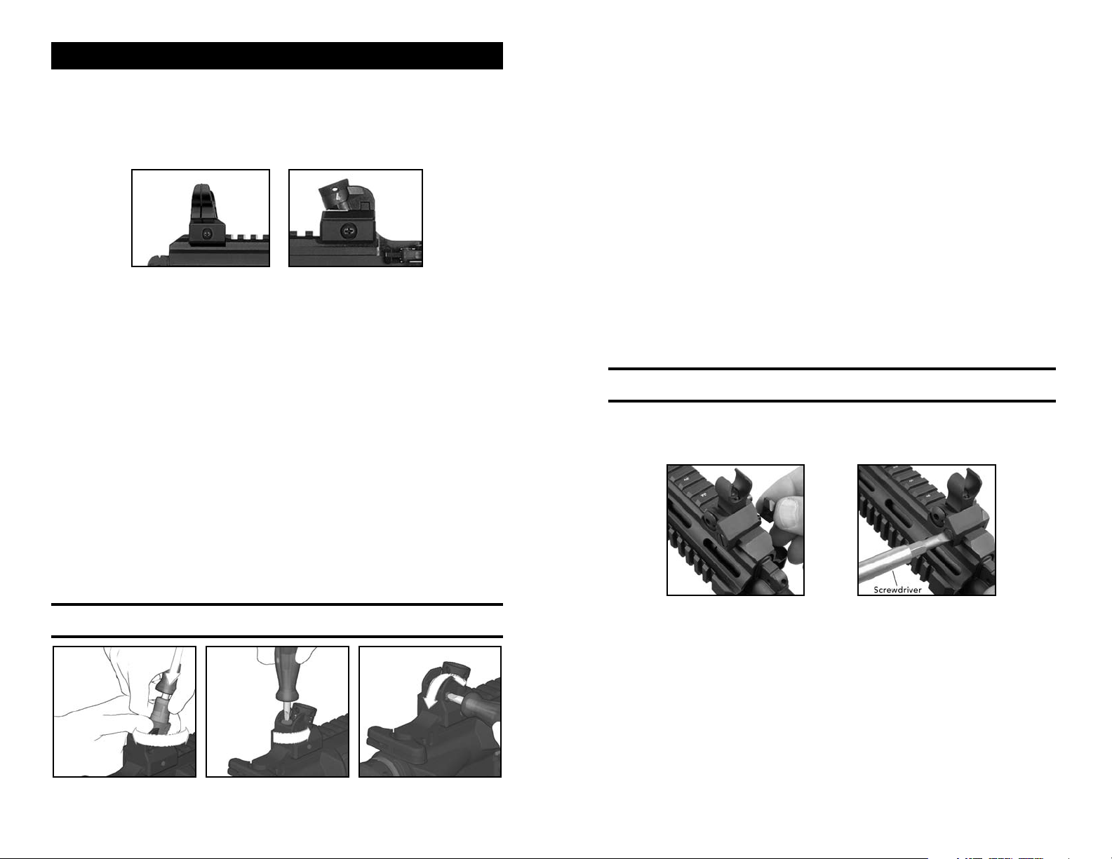
HK DIOPTER SIGHTS
For models with HK Diopter rotary sight sets, the sights are installed on the MIL-STD1913 (Picatinny) rail with a Phillips #2 screwdriver or the HK sight tool (Fig. 5 & 6). Do not
over tighten the screws.
Fig. 5 – Front Diopter Sight Fig. 6 – Rear Diopter Sight
For optimal sight use and the longest sight radius, the front sight is installed on the
most forward portion of the MIL-STD-1913 rail and the rear sight is installed on the
most rearward portion of the MIL-STD-1913 rail (located on the upper receiver). Sight
adjustment is as follows:
The sight adjustment is a rear sight adjustment, so the movement of the sight will be
in the same direction the shooter wants the impact of the round to move. If the hit is
to the right of the intended location, then the sights and the impact must be moved
left. Any corrections which may be required when sighting-in the weapon may only be
performed by adjusting the rear sight for elevation or windage. MR rifles are designed to
be sighted in at a range of 100 meters. REMEMBER THIS FORMULA: LL=C (Lower or Left
= Clockwise rotation)
ELEVATION ADJUSTMENT (Alternative method without sight tool)
Use of the HK Sight Adjustment Tool (HK ID # 300009) is always recommended to adjust
the windage and elevation on any HK firearms equipped with standard diopter sights.
However, some needle nose pliers can be substituted in the event that a sight adjustment
tool is not available to perform range adjustments.
Ensure that the MR556A1 is unloaded before performing any adjustment to the sights.
Use needle noose pliers with smooth jaws rather the serrated jaws as the serrated
surfaces may cause chips and burrs on the spring loaded catch bolts. Simply insert the
jaws onto the small shelf on the catch bolts and carefully squeeze while simultaneously
rotating the drum. This action withdraws the catch bolts and allows the drum to be
rotated either clockwise or counter-clockwise. To lower the point of impact, rotate the
drum clockwise and to raise the point of impact, rotate the drum counter-clockwise.
Ensure that the catch bolts engage the vertical slots located on the inside of the drum
after removing the needle nose pliers.
WINDAGE ADJUSTMENT
Point of impact, left: Loosen clamping screw on top of sight base (Fig. 8). Turn adjusting
screw on the right side counterclockwise (Fig. 9) in accordance with the required
correction. Then retighten clamping screw. This will move the impact to the Right.
Point of impact, right: Loosen clamping screw (Fig. 8). Turn adjusting screw clockwise
(Fig. 9) until the required correction has been performed. Then retighten clamping screw.
This will move the impact to the Left.
NOTE: Each revolution of the Windage screw will move the impact of the round 15.2
cm (6 inches) at 100 meters.
TROY ACCESSORY SIGHTS
Some MR556A1 ries are supplied with Troy Industries Micro Folding Sights. Aiming and
sight picture are similar to using the HK diopter sights.
ELEVATION ADJUSTMENT
Insert elevation adjustment tool into the rear sight cylinder so that the wedges of the tool
engage in the two slots in the cylinder which contain the catch bolts. Press Phillips-head
screwdriver downward into the adjustment tool and hold firmly. Rotate rear sight cylinder
manually in the desired direction (Fig. 7).
After correction withdraw Phillips-head screwdriver and remove elevation adjustment tool.
The catch bolts will then re-engage in the slots. After performing the elevation
adjustment set the desired aperture again.
NOTE: One-quarter turn of the rear sight drum will move the impact of the round
approximately 3.8 centimeters (1.5 inches) at 100 meters
Fig. 7 – Rear Fig. 8 – Clamping Screw Fig. 9 – Windage
Sight Adjustment (to tighten turn clockwise) Adjustment
Fig. 10 – Installing front TROY sight Fig. 11 – Tightening front TROY sight
INSTALLING TROY ACCESSORY SIGHTS (FRONT)
1. Unscrew clamping assembly and place the sights at the desired location on the
Picatinny rail (Fig. 10).
2. Apply one drop of tread locking compound to the exposed threads of the clamping
screw. Replace the clamping plate and tighten the clamping screw while pushing
sight forward against the cross-slot (Fig. 11). To raise the sight, grasp and pull up
until the sights locks in the upright position. To fold the sight, depress the button on
the left side of the base and fold down. (Fig. 12)
16
17
Fig. 12 – Folding (lowering) Fig. 13 – Lowered sight
TROY front sight TROY front sights
INSTALLING TROY REAR SIGHTS
1. The rear TROY sight installs similar to the front sights. Unscrew clamping assembly
and place the sights at the desired location on the Picatinny rail.
2. To raise the sight, grasp and pull up until the sights locks in the upright position. To
fold (lower) the sight, depress the button on the left side of the base and fold down.
(Fig. 14-16)
Fig. 14 – Rear Sight Fig. 15 – Lowering Fig. 16 – Rear sight
Rear Sight folded (lowered)
FRONT SIGHT ADJUSTMENT ZEROING
1. Fire a group of four (4) shots and measure the average distance for point-of -aim to
point-of-impact.
2. Adjust front sight for elevation only.
3.Windage adjustments are made with the rear sight.
4. Confirm zero with a group of four aimed shots and adjust is necessary
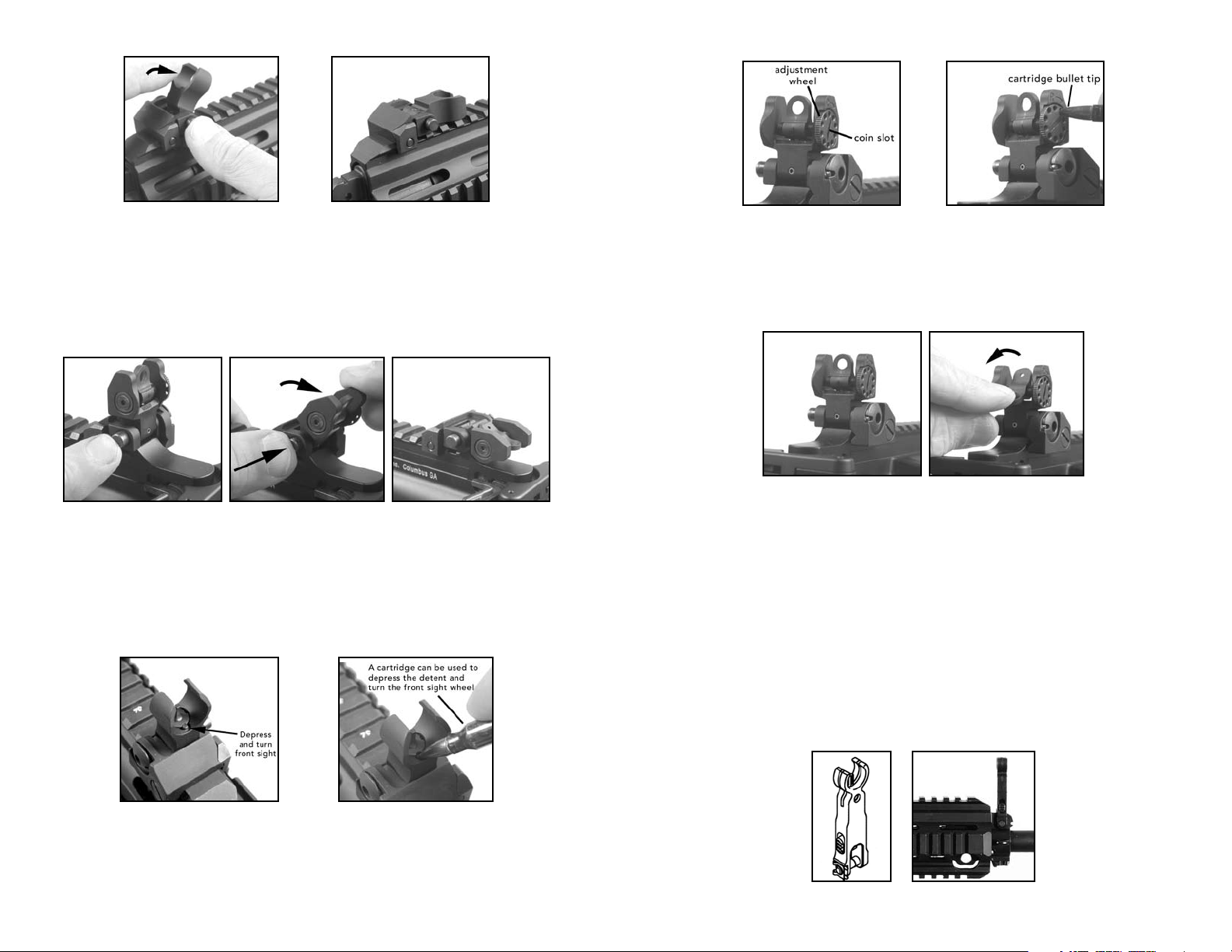
Fig. 19 – Rear Sight Fig. 20 – Windage adjustment
REAR SIGHT ADJUSTMENT
Windage adjustment can be made by inserting a pointed object (like a bullet tip) or a flat
object (like a screwdriver or coin) into the coin slot and turning the adjustment wheel. To
move the bullet impact right, turn the adjustment wheel to the right/clockwise. To move
the bullet impact left, turn the adjustment wheel to the left /counter clockwise (Fig. 19 &
20).
Fig. 21 – Rear Sight Fig. 22 – Changing aperture
The Troy rear sight also offers a choice of two flip-style apertures, both large and small
(Fig. 22). The large aperture is for close engagement and the small aperture is for more
distant shooting. Generally the large aperture works best for alignment with the front sight
and for short and medium ranges. Elevation does not change when switching apertures.
For long range shots, the small aperture can be ipped into position by nger pressure on
the top of the rear sight.
Value for 1 click of adjustment Troy Micro Sights 100 meters 200 meters 300 meters
M4/HK416/MR556A1 sight radius .50 MOA 5/8” 1-1/8” 1-5/8”
Fig. 17 – Front sight adjustment Fig. 18 – Using a bullet tip
to adjust the front sight
FRONT SIGHT ADJUSTMENT
To move the bullet impact up, turn the adjustment wheel to the right/clockwise (Fig. 17
& 18). To move the bullet impact down, turn the adjustment wheel to the left/counter
clockwise (Fig. 18 & 19).
INSTALLING THE OPTIONAL HK FLIP-UP FRONT SIGHT
Press front sight onto front sight holder until the axes holes of front sight and front sight
holder are aligned. Push through front sight axles all the way, from the right to the left and
secure the front sight axles by snapping the retaining clip. Check function of foldable front
sight (Fig. 23 & 24).
Fig. 23 Fig. 24
18
19
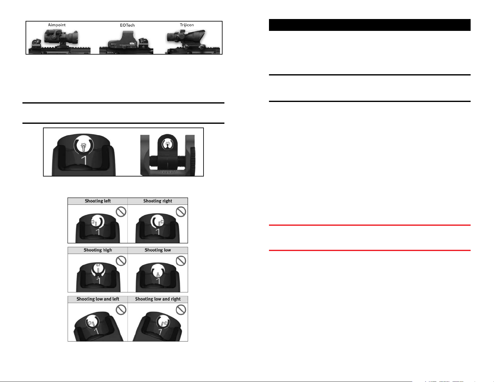
Fig. 25
A wide variety of mechanical, optical, and telescopic sights can be installed directly on
the upper MIL-STD-1913 rail (examples, Fig. 25), either on the upper receiver portion of
the rail or on the Free Floating Rail System. For sight alignment and zeroing, follow the
instructions of the sight and scope manufacturers. General mechanical sight alignment
information is depeicted in Fig. 26-27.
NOTE: Do not overtighten scopes, aimers, or any other accessories mounted on any
of the MIL-STD-1913 (Picatinny) rail surfaces of the MR556A1. Overtightening can
damage the rails.
Fig. 26 – Correct Aiming, HK diopter sights (left) and TROY sights (right)
SECTION 5 — AMMUNITION
By using ammunition with match bullets or other match grade ammunition the MR556A1
will achieve the best level of accuracy. Use ammunition of the appropriate caliber and of
recent manufacture. The MR556A1 is chambered for 5.56 x 45 mm ammunition and will
functioned safely and reliably with most high quality 5.56 mm and Caliber .223 Remington
ammunition.
NOTE: Use only high quality 5.56 x 45 mm NATO or caliber .223 Remington
ammunition in the MR556A1 rifle. Damage caused by the use of improperly assembled
or remanufactured ammunition may void the HK Warranty. Do not use ammunition
assembled with corrosive components (primers, propellants, etc.).
The MR556A1 is designed to use ammunition made to NATO or SAAMI specications.
DO NOT USE
• Reloads or remanufactured ammunition. Beware of military surplus, foreign or outdated
ammunition.
• Non-jacketed or exposed lead ammunition.
• Corrosive ammunition (primer and/or propellant).
• Empty cases as “dummy“ (inert) rounds, as damage may result. Use complete dummy
rounds available for training purposes.
• Any ammunition that exceeds NATO or SAAMI (Sporting Arms and Ammunition
Manufacturers’ Institute) pressure limits.
• Cartridges that are not 5.56 x 45 mm or Caliber .223.
• Seriously corroded ammunition.
• Dented Cartridges.
• Cartridges with loose bullets.
• Cartridges exposed to extreme heat above 135°F (57°C) until they have cooled.
• Use only authorized ammunition that is manufactured to NATO and SAAMI specs.
• Ammunition that is wet or dirty.
Fig. 27 – Aiming Errors
WARNING: Only use ammunition designed to NATO and SAAMI specifications that
is factory-loaded, undamaged, and of the correct caliber. The use of low powered
cartridges could lead to functional stoppages (including bullets stuck in the barrel)
and is not recommended.
 Loading...